

Page 1
MMVV33™™ BBaarriiaattrriicc BBeedd
MMaaiinntteennaannccee MMaannuuaall
5900
5900-009-002 Rev A.0
EN
2019/08
Page 2

Page 3
SSyymmbboollss
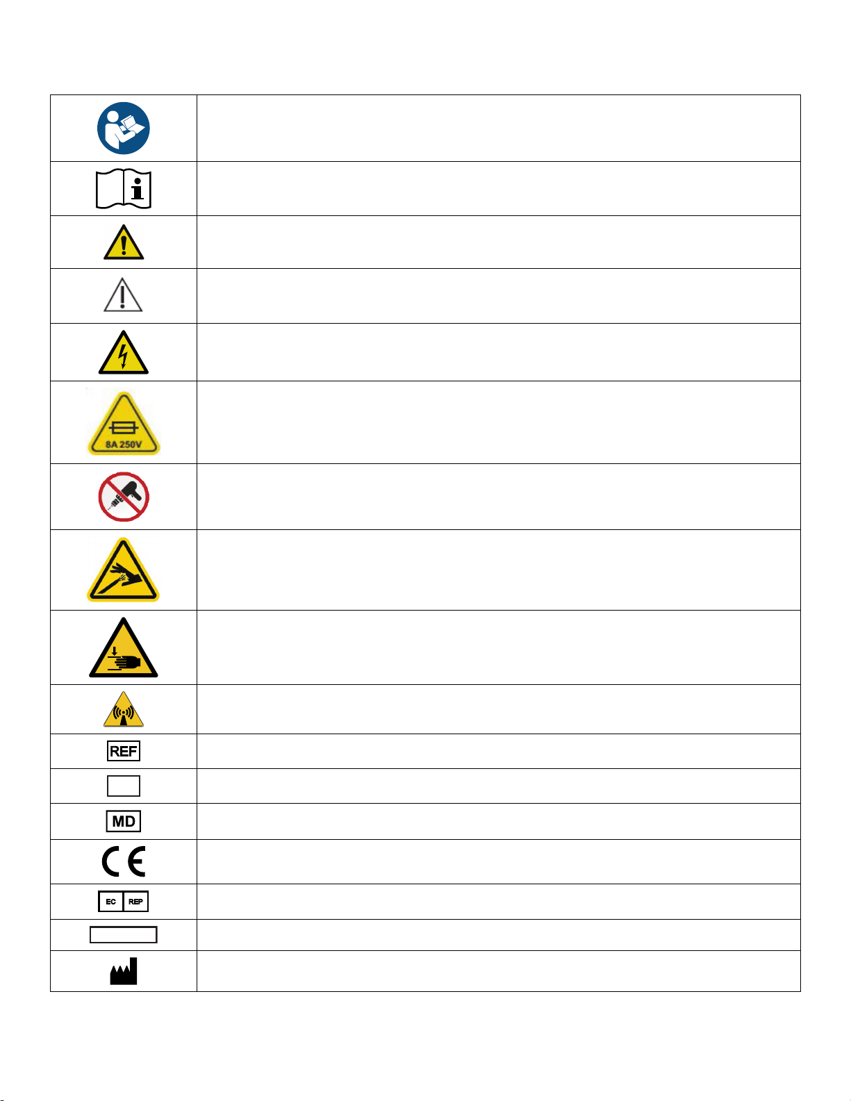
Refer to instruction manual/booklet
Operating instructions/Consult instructions for use
General warning
Caution
Warning; electricity
Fuse rating
Do not drill
Hydraulic oil pressure
Pinch/crush hazard
Non-ionizing radiation
Catalogue number
Serial number
European medical device
CE mark
5900-009-002 Rev A.0 EN
Authorized representative in the European Community
For US Patents see www.stryker.com/patents
Manufacturer
Page 4
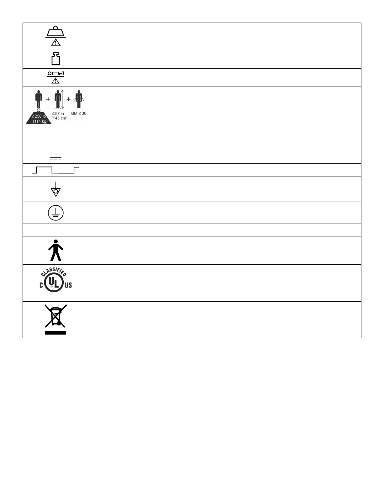
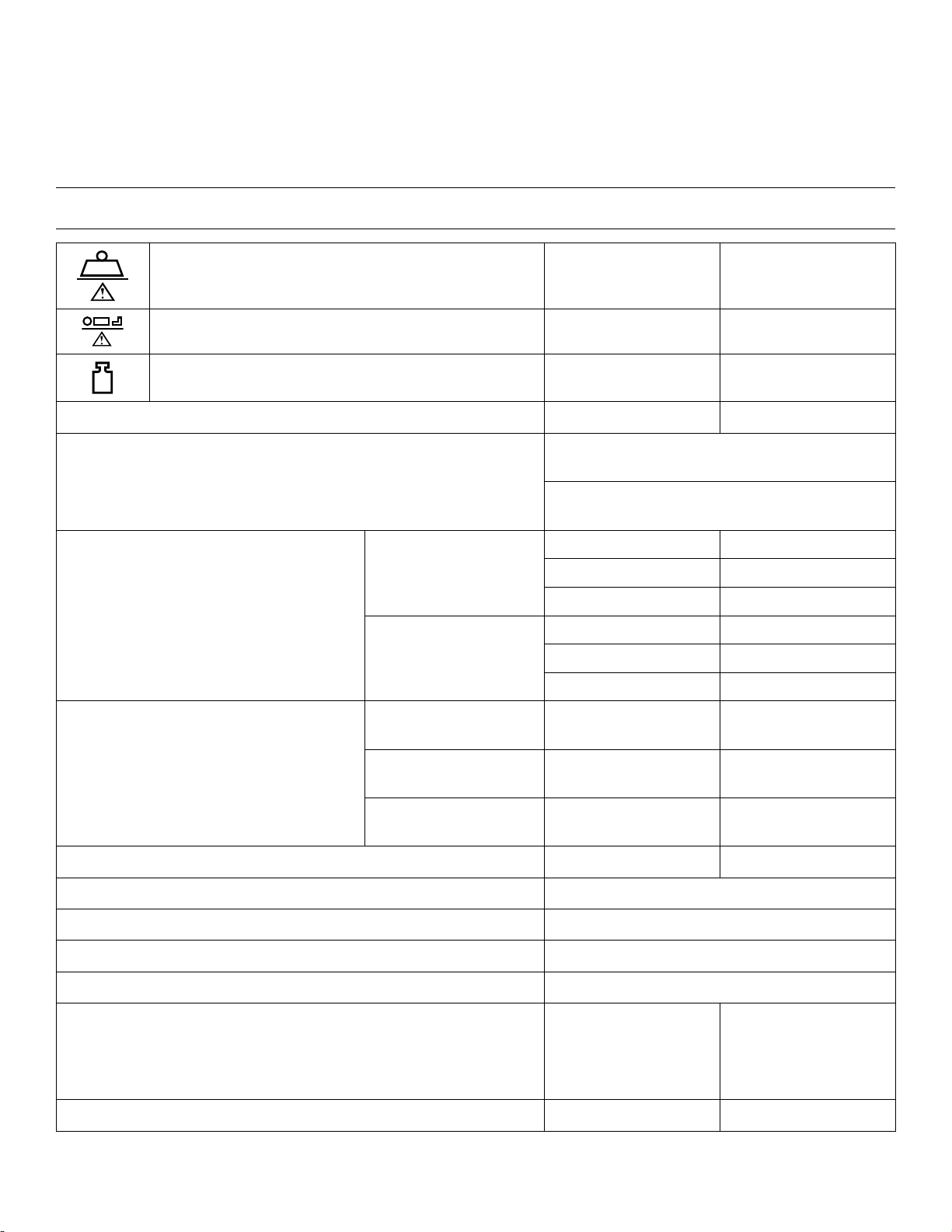
Safe working load
~
≤2m ≥18m
87VL
Mass of equipment
Maximum patient weight
Adult patient biometrics
Alternating current
Direct current
Duty cycle of product
Unit provides terminal for connection of a potential equalization conductor. The potential
equalization conductor provides direct connection between the unit and potential equalization
busbar of the electrical installation.
Protective earth ground
IIPPXX44
Protection from liquid splash
Type B applied part
Medical Equipment Classified by Underwriters Laboratories Inc. With Respect to Electric Shock,
Fire, and Mechanical Hazards Only in Accordance with ANSI/AAMI ES60601-1:2005/(R)2012
and A1:2012 C1:2009/(R)2012 and A2:2010/(R)2012, CAN/CSA-C22.2 No. 60601-1:14, IEC
60601-2-52:2009/A1:2015, CAN/CSA-C22.2 No. 60601-2-52:11 with Amendment 1:2017.
In accordance with European Directive 2012/19/EU on Waste Electrical and Electronic
Equipment (WEEE) as amended, this symbol indicates that the product should be collected
separately for recycling. Do not dispose of as unsorted municipal waste. Contact local distributor
for disposal information. Ensure infected equipment is decontaminated prior to recycling.
EN 5900-009-002 Rev A.0
Page 5

TTaabbllee ooff CCoonntteennttss
Warning/Caution/Note Definition ..............................................................................................................................3
Summary of safety precautions ................................................................................................................................4
Introduction ...............................................................................................................................................................5
Product description .................................................................................................................................................5
Indications for use ...................................................................................................................................................5
Clinical benefits ......................................................................................................................................................5
Expected service life ...............................................................................................................................................5
Disposal/recycle.................................................................................................................................................5
Contraindications ....................................................................................................................................................6
Specifications .........................................................................................................................................................6
Product illustration ..................................................................................................................................................8
Contact information .................................................................................................................................................8
Serial number location.............................................................................................................................................9
Preventive maintenance .........................................................................................................................................10
Error codes ............................................................................................................................................................. 12
Electrical diagram ................................................................................................................................................... 18
Cable routing...........................................................................................................................................................19
Maintenance menu ................................................................................................................................................. 20
Language............................................................................................................................................................. 20
Set clock .............................................................................................................................................................. 20
Actuator maintenance ...........................................................................................................................................21
Scale maintenance ............................................................................................................................................... 21
Calibrate scale .................................................................................................................................................22
Angle maintenance ...............................................................................................................................................22
Calibrate angles ...............................................................................................................................................22
Width maintenance ...............................................................................................................................................23
Calibrate deck widths........................................................................................................................................ 23
Patient station....................................................................................................................................................... 24
Test modes ..........................................................................................................................................................24
Battery maintenance .............................................................................................................................................24
Service ....................................................................................................................................................................25
Protecting against electrostatic discharge (ESD) .....................................................................................................25
Battery replacement ..............................................................................................................................................25
Caster replacement...............................................................................................................................................26
Main control board replacement .............................................................................................................................26
AVB board replacement ........................................................................................................................................27
Footboard keypad/display replacement ..................................................................................................................28
Footboard main cable replacement ........................................................................................................................28
Fowler actuator replacement.................................................................................................................................. 29
Gatch actuator replacement................................................................................................................................... 29
Thigh actuator replacement ...................................................................................................................................30
Lift actuator replacement (head/foot) ...................................................................................................................... 31
Load cell board replacement, head end and foot end ............................................................................................... 31
Load cell assembly replacement ............................................................................................................................ 32
Siderail replacement, head end..............................................................................................................................33
Siderail replacement, foot end................................................................................................................................33
IV pole attachment ................................................................................................................................................34
Patient helper attachment ......................................................................................................................................34
Top level assembly .................................................................................................................................................36
Upper frame assembly............................................................................................................................................ 41
Deck assembly, seat section .................................................................................................................................. 47
Deck pan assembly, seat deck, patient right.......................................................................................................... 54
5900-009-002 Rev A.0 1 EN
Page 6

Deck pan assembly, seat deck, patient left ............................................................................................................ 55
Deck assembly, head section ................................................................................................................................. 56
Deck pan assembly, head deck, patient right......................................................................................................... 65
Deck pan assembly, head deck, patient left ...........................................................................................................66
Lock assembly, head deck position........................................................................................................................ 67
Deck assembly, knee section .................................................................................................................................68
Deck pan assembly, knee deck, patient right.........................................................................................................72
Deck pan assembly, knee deck, patient left ...........................................................................................................73
Deck assembly, foot section ...................................................................................................................................74
Deck pan assembly, foot deck, patient right...........................................................................................................81
Deck pan assembly, foot deck, patient left .............................................................................................................82
HILO frame assembly ............................................................................................................................................. 83
Lower frame assembly............................................................................................................................................ 87
Caster frame assembly........................................................................................................................................... 89
Rail assembly, head ...............................................................................................................................................93
Rail assembly, foot ............................................................................................................................................... 101
Timing link assembly ............................................................................................................................................ 108
Rail arm assembly, power/communication........................................................................................................... 109
Rail arm assembly, nurse call/speaker................................................................................................................. 110
Rail arm assembly, no cable................................................................................................................................. 111
Bracket assembly, lower rail slide ........................................................................................................................ 112
Latch lock assembly, left head/right foot - 5900200023....................................................................................... 113
Latch lock assembly, right head/left foot - 5900200024....................................................................................... 114
Power supply cord ................................................................................................................................................ 115
Accessory cord, type B 120V................................................................................................................................ 116
Footboard assembly - 5900200025...................................................................................................................... 117
Expandable headboard assembly - 5900200026................................................................................................. 120
EMC information ................................................................................................................................................... 123
0039-254-000 ....................................................................................................................................................... 128
5900400037, 5900400040.................................................................................................................................... 129
5900400038.......................................................................................................................................................... 130
5900470017.......................................................................................................................................................... 131
5900470018, 5900470019.................................................................................................................................... 132
EN 2 5900-009-002 Rev A.0
Page 7

WWaarrnniinngg//CCaauuttiioonn//NNoottee DDeeffiinniittiioonn
The words WWAARRNNIINNGG, CCAAUUTTIIOONN, and NNOOTTEE carry special meanings and should be carefully reviewed.
WWAARRNNIINNGG
Alerts the reader about a situation which, if not avoided, could result in death or serious injury. It may also describe
potential serious adverse reactions and safety hazards.
CCAAUUTTIIOONN
Alerts the reader of a potentially hazardous situation which, if not avoided, may result in minor or moderate injury to the
user or patient or damage to the product or other property. This includes special care necessary for the safe and effective
use of the device and the care necessary to avoid damage to a device that may occur as a result of use or misuse.
NNoottee -- Provides special information to make maintenance easier or important instructions clearer.
5900-009-002 Rev A.0 3 EN
Page 8

SSuummmmaarryy ooff ssaaffeettyy pprreeccaauuttiioonnss
Always read and strictly follow the warnings and cautions listed on this page. Service only by qualified personnel.
WWAARRNNIINNGG
• Always use this product for bariatric use only per the details on the product labeling and specifications from this manual.
• Do not use this product for psychiatric, pediatric, or home health care use.
• Do not use this product in an oxygen rich environment.
• Always use Stryker approved mattresses that have been tested for compatibility with the product frame to avoid the risk
of patient entrapment.
• Do not lower the litter too low or the litter may not be supported.
• The use of accessories, transducers, and cables, other than those specified or provided by the manufacturer, could
result in increased electromagnetic emissions or decreased electromagnetic immunity and result in improper operation.
• Portable RF communications equipment, including peripherals such as antenna cables and external antennas, should
be no closer than 12 inches (30 cm) to any part of MMVV33, including cables specified by the manufacturer.
• Avoid stacking or placing equipment adjacent with other equipment to prevent improper operation of the products. If
such use is necessary, carefully observe stacked or adjacent equipment to make sure that they are operating properly.
CCAAUUTTIIOONN
• Improper usage of the product can cause injury to the patient or operator. Operate the product only as described in this
manual.
• Do not modify the product or any components of the product. Modifying the product can cause unpredictable operation
resulting in injury to patient or operator. Modifying the product also voids its warranty.
• Always make sure that the product is clear of obstacles before you use motion functions.
• Always calibrate the product angles when you replace the main control board or any actuator or product damage may
occur.
• Always use ESD protective equipment before opening antistatic bags and servicing electronic parts.
• Do not place unprotected circuit boards on the floor.
• Always perform this procedure in a secure location with the floor jack secure to the base frame before you remove the
caster to prevent the risk of injury.
• Do not put your hands or feet below the caster when you remove or attach the caster to prevent the risk of injury.
• Always leave the bolts loose in the support holes, so the bolt head is out far enough to stop the lift mechanism slide
block.
EN 4 5900-009-002 Rev A.0
Page 9

IInnttrroodduuccttiioonn
This manual assists you with the operation or maintenance of your Stryker product. Read this manual before operating or
maintaining this product. Set methods and procedures to educate and train your staff on the safe operation or maintenance
of this product.
CCAAUUTTIIOONN
• Improper usage of the product can cause injury to the patient or operator. Operate the product only as described in this
manual.
• Do not modify the product or any components of the product. Modifying the product can cause unpredictable operation
resulting in injury to patient or operator. Modifying the product also voids its warranty.
NNoottee
• This manual is a permanent part of the product and should remain with the product even if the product is sold.
• Stryker continually seeks advancements in product design and quality. This manual contains the most current product
information available at the time of printing. There may be minor discrepancies between your product and this manual. If
you have any questions, contact Stryker Customer Service or Technical Support at 1-800-327-0770.
PPrroodduucctt ddeessccrriippttiioonn
The Stryker model 5900 MMVV33™™ bariatric hospital bed is an AC-powered adjustable hospital bed designed to be utilized with
a patient support surface matching the deck size of the bed frame. MMVV33 consists of a Fowler and knee Gatch to aid in the
adjustment of the surface contour of the bed, moveable and latchable siderails, and electronic controls located in the
footboard and siderails. The
positioning and provides visual alerts when those parameters set by the health care professional (HCP) are altered.
ii
BBeedd®® Awareness system allows users to set various bed parameters to monitor bed
IInnddiiccaattiioonnss ffoorr uussee
WWAARRNNIINNGG
• Always use this product for bariatric use only per the details on the product labeling and specifications from this manual.
• Do not use this product for psychiatric, pediatric, or home health care use.
• Do not use this product in an oxygen rich environment.
The MMVV33 bariatric bed is intended to provide a patient support surface for medical purposes and to provide a method of
transporting patients within a healthcare facility. It is intended to be used with bariatric, adult, non-behavioral health patients
with a BMI of 30 kg/m² or greater and weighing 250 lb (113.4 kg) or more.
CClliinniiccaall bbeenneeffiittss
Patient treatment, patient positioning, and diagnostic
EExxppeecctteedd sseerrvviiccee lliiffee
The 5900 MMVV33 bariatric bed has an eight year expected service life under normal use conditions and with appropriate
periodic maintenance.
The backup batteries have a one year expected service life under normal use conditions.
DDiissppoossaall//rreeccyyccllee
Always follow the current local recommendations and/or regulations governing environmental protection and the risks
associated with recycling or disposing of the equipment at the end of its useful life.
5900-009-002 Rev A.0 5 EN
Page 10
CCoonnttrraaiinnddiiccaattiioonnss
None known.
SSppeecciiffiiccaattiioonnss
WWAARRNNIINNGG -- Always use Stryker approved mattresses that have been tested for compatibility with the product frame to
avoid the risk of patient entrapment.
Safe working load
NNoottee:: Safe working load indicates the sum of the
occupant, accessories, and mattress weight.
1102 lb
500 kg
Maximum patient weight
Product weight
Scale system capacity maximum 1102 lb 500 kg
± 4.4 lb (2 kg) for patients weighing 225 (102 kg)
to 882 lb (400 kg)
Scale system accuracy
± 6.6 lb (3 kg) for patients weighing 886 (402 kg)
to 1102 lb (500 kg)
92 in. x 38.3 in. 233.7 cm x 97.2 cm
Overall length and width
Patient sleep surface
Siderails stowed
Siderails at low,
intermediate, and high
position
36 in. (91.4 cm) deck
position
42 in. (106.7 cm) deck
position
92 in. x 42 in. 233.7 cm x 106.7 cm
92 in. x 48 in. 233.7 cm x 121.9 cm
92 in. x 40.5 in. 233.7 cm x 102.9 cm
92 in. x 46.5 in. 233.7 cm x 118.1 cm
92 in. x 52.5 in. 233.7 cm x 133.4 cm
80 in. x 34.5 in.
80 in. x 40.5 in.
1027 lb
902 lb
203.2 cm x 87.6 cm
203.2 cm x 102.9 cm
465.8 kg
409.1 kg
48 in. (121.9 cm) deck
position
Bed height to top of seat litter
Knee Gatch position 0° to 20° ± 2°
Fowler position
Foot position
Trendelenburg and reverse Trendelenburg
Electrical requirements
NNoottee -- Class I Electrical Equipment: Protection against electrical
shock relies on connection to protective earth of an appropriately
rated hospital grade outlet.
Hospital grade GFCI auxiliary outlet
EN 6 5900-009-002 Rev A.0
80 in. x 46.5 in.
12 in. to 28 in. 30.5 cm to 71.1 cm
0° to 60° ± 2°
0° to 13° ± 2°
+12° to -12°
120 VAC, 60 Hz, 8A 230 VAC, 50 Hz, 4A
120 VAC, 60 Hz, 6A
203.2 cm x 118.1 cm
230 VAC, 50 Hz, 3A
Page 11
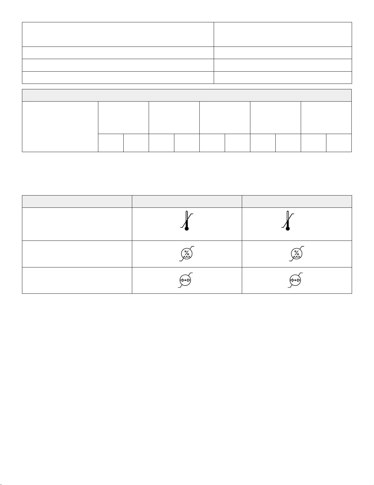
Battery voltage
95 °F
(35 °C)
50 °F
(10 °C)
140 °F
(60 °C)
-40 °F
(-40 °C)
80%
20%
95%
10%
106 kPa
70 kPa
106 kPa
50 kPa
NNoottee -- Always replace with Stryker approved batteries.
12 VDC (x2) (Stryker part number: 5900280025)
Duty cycle
2 minutes ON, 18 minutes OFF
Application environments 1, 2, 3, and 5 per IEC 60601-2-52
Maximum acoustic sound pressure
< 60 dBA
CCoommppaattiibbllee mmaattttrreessss
Bariatric non-powered
support surface
Length
Width Thickness
Bolster width,
patient right and
patient left
Bolster
thickness,
patient right and
patient left
(28850555001)
79.5
in.
201.9cm45 in. 114.3cm7 in. 17.8
cm
6 in. 15.2
cm
7 in. 17.8
NNoottee -- Minimum mattress firmness: ILD at 50% - minimum of 108 lbf
Stryker reserves the right to change specifications without notice.
Specifications listed are approximate and may vary slightly from product to product or by power supply fluctuations.
EEnnvviirroonnmmeennttaall ccoonnddiittiioonnss
OOppeerraattiioonn SSttoorraaggee aanndd ttrraannssppoorrttaattiioonn
Ambient temperature
cm
Relative humidity (non-condensing)
Atmospheric pressure
5900-009-002 Rev A.0 7 EN
Page 12
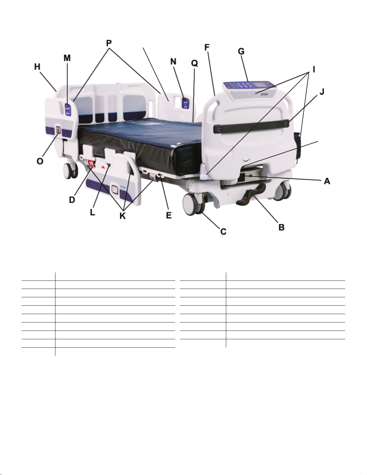
PPrroodduucctt iilllluussttrraattiioonn
R
S
FFiigguurree 11 –– MMooddeell 55990000 MMVV33 bbaarriiaattrriicc bbeedd
A
B
C Caster M
D CPR release handle N
E
F Footboard P Siderails
G
H Headboard R
I
J
120/230 VAC hospital grade GFCI outlet
Brake/steer pedal
Foley bag hooks
Footboard control panel
ii
BBeedd Awareness lights
Integrated pump rack
K
L Mattress retainer
O Siderail release button
Q
S Footboard lock switch
Mattress deck expansion handle
Operator control panel
Patient control panel
Support surface
Nurse Call speaker
CCoonnttaacctt iinnffoorrmmaattiioonn
Contact Stryker Customer Service or Technical Support at: 1-800-327-0770.
Stryker Medical
3800 E. Centre Avenue
Portage, MI 49002
USA
EN 8 5900-009-002 Rev A.0
Page 13
NNoottee -- The user and/or the patient should report any serious product-related incident to both the manufacturer and the
A
Competent authority of the European Member State where the user and/or patient is established.
To view your operations or maintenance manual online, see https://techweb.stryker.com/.
Have the serial number (A) of your Stryker product available when calling Stryker Customer Service or Technical Support.
Include the serial number in all written communication.
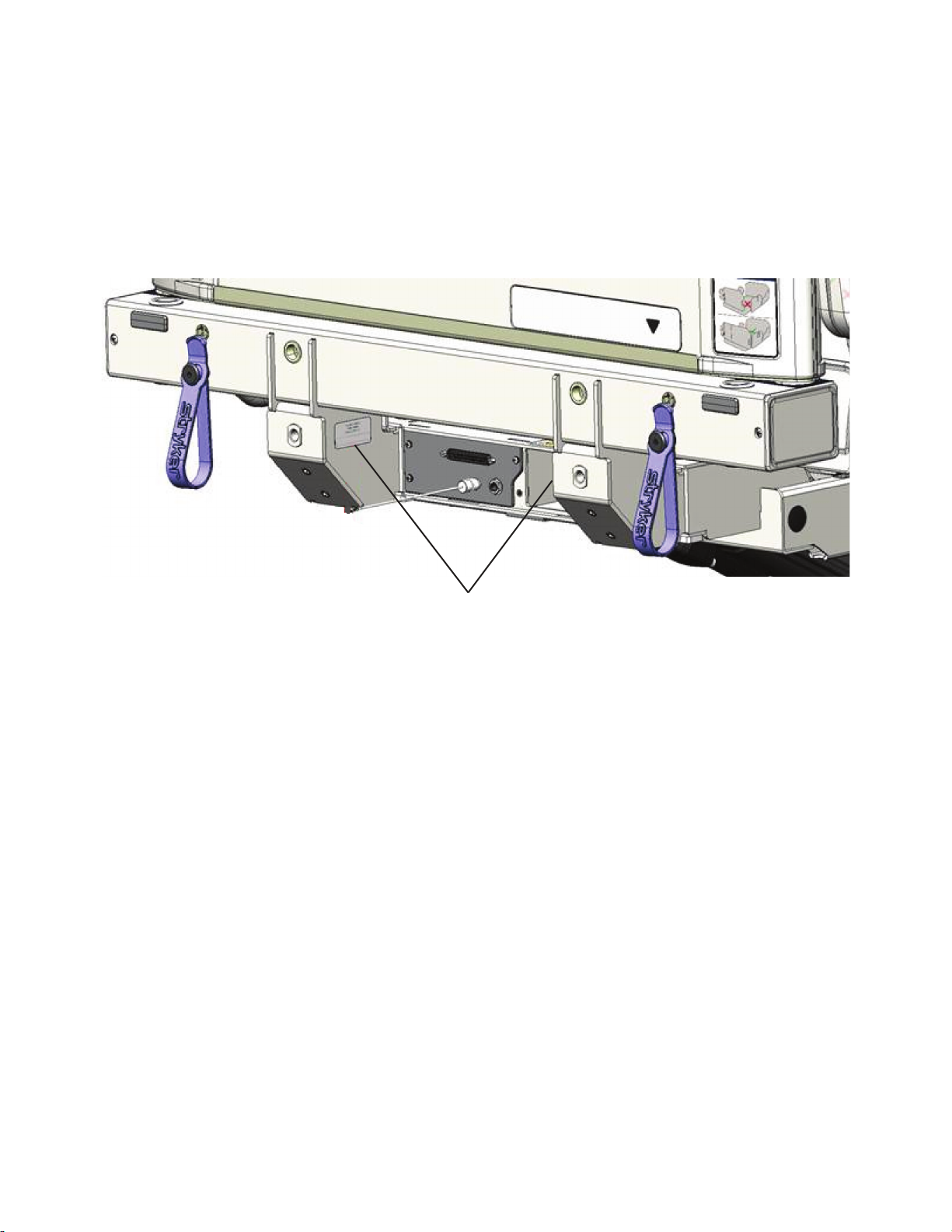
SSeerriiaall nnuummbbeerr llooccaattiioonn
You can find the serial number (A) below the headboard at the head of the bed (Figure 2).
FFiigguurree 22 –– SSeerriiaall nnuummbbeerr llooccaattiioonn--ooppeerraattoorr vviieeww
5900-009-002 Rev A.0 9 EN
Page 14

PPrreevveennttiivvee mmaaiinntteennaannccee
Remove the product from service before you perform the preventive maintenance inspection. Make sure that all items listed
during annual preventive maintenance for all Stryker Medical products. You may need to perform preventive maintenance
checks more often based on your level of product usage. Service only by qualified personnel.
NNoottee -- Clean and disinfect the exterior of the support surface before inspection, if applicable.
Inspect the following items:
All welds
All fasteners are secure
Casters lock with brake pedal applied
Casters are secure and swivel
Casters are free of wax and debris
Center light LED and bumper LEDs flash when brakes are released
Steer function works
Siderails move, latch, and stow
Deck expands, retracts, and locks in all positions
CPR release operates
IV pole is intact and operates (option)
Foley bag hooks intact
No cracks or splits in headboard, footboard or siderail panels
No rips or cracks in mattress cover
All functions on head end siderails operate (includes LEDs)
All functions on footboard operate (includes LEDs)
No cracks or damage to control overlays
Scale system calibrated
Night light operates
Power cords and plug not frayed or damaged
No cables worn or pinched
No damage to nurse call connections
All electrical connections tight
All ground strap cables are secure to the frame
Ground impedance not more than 200 mΩ (milliohms)
Current leakage not more than 300 µA (microamps)
Apply grease to the litter grease points (see maintenance manual for locations)
Ground chains intact
Trendelenburg/reverse Trendelenburg angle accuracy is minimum +12° to -12°
Fowler angle accuracy is 0° - 60° ± 2°
Fowler holds position at 30° with weight
Siderail switches operate (iiBBeedd Awareness)
Center light LED and bumper LEDs operate (iiBBeedd Awareness)
Inspect footboard control labels for signs of degradation
EN 10 5900-009-002 Rev A.0
Page 15

Inspect hi-lo actuators for oil leaks
Inspect footboard connector housing for cracks or damage
All motions function
Nurse call functions
Auxiliary outlets function (test ground fault interrupter)
Replace batteries (one year expected service life)
Set clock to local date and time
Product serial number:
Completed by:
Date:
5900-009-002 Rev A.0 11 EN
Page 16

EErrrroorr ccooddeess
Error codes are detailed in the table below.
EErrrroorr ccooddee CCaauussee
0.02 Error on non volatile memory
(nvm)
0.03 Watchdog switch in wrong position or broken
(comWatchdogDisabled)
0.04 Software version mismatched or missing board
(softwareVersionMismatch)
0.05 Brake switch malfunction
(brake)
0.06 Obstruction switch malfunction
(obstruction)
0.07 CPR switch/cable malfunction
(cprHandle)
0.08 FSC_KPD board is not responding
(FSC_KPD_missing)
TTrroouubblleesshhoooottiinngg
1. Reboot product
2. Replace MCU
1. Toggle watchdog switch on MCU
1. Reboot product
2. Check for a missing board error, if missing take
corrective action on cable or board
1. Check brake cable and switch
1. Check each of the four obstruction switches and
cables
1. Check CPR switch, cable, and head actuator
1. Check cable
2. Check AVB board (electrical issue)
0.09 FSC_GUI board is not responding
(FSC_GUI_missing)
0.1 SRK PL board is not responding
(SRK_PL_missing)
0.11 SRK PR board is not responding
(SRK_PR_missing)
0.12 PSI board is not responding
(PSI_missing)
1. Check cable
2. Check FSC_KPD
• Software in bootloader mode
• Software incorrect
• Electrical issue
3. AVB board (electrical issue)
1. Check cables
2. Check junction boards
3. Check SRK board
4. Check SRC (software and electrical)
1. Check cables
2. Check junction boards
3. Check SRK board
4. Check SRC (software and electrical)
1. Check cables
2. Check junction boards
EN 12 5900-009-002 Rev A.0
Page 17

EErrrroorr ccooddee CCaauussee
TTrroouubblleesshhoooottiinngg
0.13 ACB HILO foot board is not responding
(ACB_HILO_FT_missing)
0.14 ACB HILO head board is not responding
(ACB_HILO_HD_missing)
0.15 ACB foot board is not responding
(ACB_FT_missing)
0.16 ACB head board is not responding
(ACB_HD_missing)
0.17 ACB knee board is not responding
(ACB_KN_missing)
0.18 SRC foot patient left board is not responding
(SRC_FT_PL_missing)
0.19 SRC head patient left board is not responding
(SRC_HD_PL_missing)
1. Check cables
2. Check junction boards
1. Check cables
2. Check junction boards
1. Check cables
2. Check junction boards
1. Check cables
2. Check junction boards
1. Check cables
2. Check junction boards
1. Check cables
2. Check junction boards
1. Check cables
2. Check junction boards
0.2 SRC foot patient right board is not responding
(SRC_FT_PR_missing)
0.21 SRC head patient right board is not responding
(SRC_HD_PR_missing)
0.22 DPM foot board is not responding
(DPM_FT_missing)
0.23 DPM head board is not responding
(DPM_HD_missing)
0.24 DPM MID board is not responding
(DPM_MID_missing)
0.25 SMB foot board is not responding
(SMB_FOOT_missing)
0.26 SMB head board is not responding
(SMB_HEAD_missing)
1. Check cables
2. Check junction boards
1. Check cables
2. Check junction boards
1. Check cables
2. Check junction boards
1. Check cables
2. Check junction boards
1. Check cables
2. Check junction boards
1. Check cables
2. Check junction boards
1. Check cables
2. Check junction boards
5900-009-002 Rev A.0 13 EN
Page 18

EErrrroorr ccooddee CCaauussee
TTrroouubblleesshhoooottiinngg
0.27 AVB board is not responding
(AVB_missing)
0.29 Real Time Clock is not responding
(RTC chip fail)
0.3 CPR handle switch stuck
(StuckCPRhandle)
1.05 24V is out of range
(24V)
1.08 Battery not connected to the system or completely
depleted
(batteryMissing)
1.09 Damaged battery
(batteryShort)
1. Check cables
2. Check junction boards
1. Reboot product
2. Replace MCU, if 0.02 is present, also issue with
PMB charger chip
3. Replace PMB
1. Check CPR handle
2. Check pull cable
3. Check head actuator
1. Power cable issue
2. PMB ciruit error, replace PMB
1. Check cables
2. Replace battery
1. Replace batteries
1.1 Unable to communicate with accelerometer
(Accelerometer error)
1.11 HILO foot configuration error
(HiloFoot config)
1.12 HILO foot drive circuit error
(HiloFoot Drive ckt)
1.13 HILO head configuration error
(HiLo Head config)
1. Reboot product
2. Replace MCU, if 0.02 is present, also issue with
PMB charger chip
3. Replace PMB
1. WD switch position
2. Reboot product
1. Check 24V cable to ACB
2. Disconnect actuator from ACB
3. Replace ACB
1. WD switch position
2. Reboot product
3. Check HILO head potentiometer cable (30159)
4. Check HILO head counts in actuator
maintenance menu
5. Check HILO head counts in angle maintenance
menu
• Check if counts are between 1024-1033 or
not moving
6. Check HILO foot potentiometer cable (30124)
7. Recalibrate angles
EN 14 5900-009-002 Rev A.0
Page 19

EErrrroorr ccooddee CCaauussee
TTrroouubblleesshhoooottiinngg
1.14 HILO head drive circuit error
(HiLo Head Drive Ckt)
1.15 Foot actuator configuration error
(Foot config)
1.16 Foot drive circuit malfunction
(Foot Drive ckt)
1.17 Head actuator configuration error
(Head config)
1. Check 24V cable to ACB
2. Disconnect actuator from ACB
3. Replace ACB
1. WD switch position
2. Recalibrate angles
3. Reboot product
4. Check foot counts in angle maintenance menu
• Check if foot counts are stored between
power cycles
• If they are not stored, EEPROM error
5. Replace board
1. Check 24V cable to ACB
2. Disconnect actuator from ACB
3. Replace ACB
1. WD switch position
2. Reboot product
3. Check head potentiometer cable (30141)
4. Check head counts in actuator maintenance
menu
1.18 Head drive circuit malfunction
(Head Drive ckt)
1.19 Knee actuator configuration error
(Knee config)
1. Check 24V cable to ACB
2. Disconnect actuator from ACB
3. Replace ACB
1. WD switch position
2. Reboot product
3. Check knee counts in actuator maintenance
menu
• Check if knee counts are stored between
power cycles
• If they are not stored, EEPROM error
• Replace board
• Recalibrate angles
4. Check HILO foot counts in actuator
maintenance menu
• Check if counts are between 1024-1033 or
not moving
5. Check HILO foot potentiometer cable (30124)
6. Recalibrate angles
5900-009-002 Rev A.0 15 EN
Page 20

EErrrroorr ccooddee CCaauussee
TTrroouubblleesshhoooottiinngg
1.2 Knee drive circuit malfunction
(Knee Drive ckt)
1.21 PSI configuration error
(PSI config)
1.22 Patient left foot SRC configuration error
(SRC PL Foot config)
1.23 Patient left head SRC configuration error
(SRC PL Head config)
1.24 Patient right foot SRC configuration error
(SRC PR Foot config)
1. Check 24V cable to ACB
2. Disconnect actuator from ACB
3. Replace ACB
1. Replace switch if this appears only in some
positions
2. WD switch position
1. Replace switch if this appears only in some
positions
2. WD switch position
1. Replace switch if this appears only in some
positions
2. WD switch position
1. Replace switch if this appears only in some
positions
2. WD switch position
1.25 Patient right foot SRC configuration error
(SRC PR Head config)
1.26 DPM foot configuration error
(DPM FT config)
1.27 DPM head configuration error
(DPM HD config)
1.28 DPM MID configuration error
(DPM MID Config)
1. Replace switch if this appears only in some
positions
2. WD switch position
1. Calibration error
2. Trim error
• If values from DPM maintenance screen are
at 36 and less than 600, this error bit is set
3. WD switch position
1. Calibration error
2. Trim error
• If values from DPM maintenance screen are
at 36 and less than 600, this error bit is set
3. WD switch position
1. Calibration error
2. Trim error
• If values from DPM maintenance screen are
at 36 and less than 600, this error bit is set
3. WD switch position
EN 16 5900-009-002 Rev A.0
Page 21

EErrrroorr ccooddee CCaauussee
TTrroouubblleesshhoooottiinngg
1.29 SMB head configuration error
(SMB Head Config)
1.3 SMB foot configuration error
(SMB Foot Config)
1.31 AVB configuration error
(AVB Foot Config)
1. Load cell missing
2. EEPROM error on board
3. Secondary scale missing (also will set 0.25)
4. WD switch position
1. Load cell missing
2. EEPROM error on board
3. Secondary scale missing (also will set 0.25)
4. WD switch position
1. WD switch position
5900-009-002 Rev A.0 17 EN
Page 22
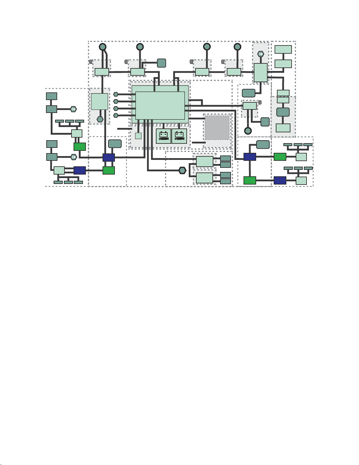
EElleeccttrriiccaall ddiiaaggrraamm
AVB 5900280034
+12VDC+12VDC
J21
MAINS AC TO DC
POWER SUPPLY
5900410023
+12VDC+12VDC
5900430029
USB
5900410022
DC POWER - 5900280025
AC POWER - 5900280026
SMB HEAD - 5900280039
2
5
PEIZO SPE
AKER
5900280035
MID DECK FRAME (SEAT)
HEAD DECK FRAME
(FOWLER)
5900430156
5900410002 5900410002
5900410002
ALT TUCK
LOCKTUCK
5900430156
5900410002 5900410002
5900410002
ALT TUCK
LOCKTUCK
5900430156
5900410002 5900410002
5900410002
ALT TUCK
LOCKTUCK
5900430156
5900410002 5900410002
5900410002
ALT TUCK
LOCKTUCK
PCBA, S1 JCTN
PL-OUT PR-IN
5900400052
5900430059
5900430059
PCBA, S1 JCTN
PL-IN PR-OUT
5900400051
PL HEAD
RAIL SRC
590040004201
PR HEAD
RAIL SRC
590040004202
PR PATIENT
RAIL SRK
5900470018
PR STAFF
RAIL SRK
5900470025
5900430044
PL PATIENT
RAIL SRK
5900470019
PL STAFF
RAIL SRK
5900470026
5900430044
59002
80009
SPEAKER
5900430036
FOOT DECK FRAME
5900430060
5900430060
UPPER LITTER FRAME
5900200094
3 1
4
UNDERBED ENCLOSURE
LOWER FRAME
UPPER
BLINDMATE
LOWER
BLINDMATE
PCBA
S1 IOM AVB
5900400039
PCBA, S1 IOM PSI
5900400038
[DB37 BED PORT]
1/4
JACK
EHA
5900430118
LA31
EHA
5900430118
PCBA, S1 JCTN
PL-OUT PR-IN
5900400052
iBED BUMPER
LIGHT ASSY
5900280053
iBED BUMPER
LIGHT ASSY
5900280053
iBED LIGHT
5900400032
5900430131
5900430148
5900430162
5900430133
5900200152
5900430161
5900410022
5900430146
5900430146
5900430083
5900430146
5900430147
5900430030
5900430091
5900430092
5900430144
5900430159
5900430124
5900430155
590043012
3
5900430141
590043014
2
HEAD ACTUATOR W/ CPR
5900420009
HILO HEAD ACTUATOR
5900420010
HILO FOOT ACTUATOR
5900420010
FOOT ACTUATOR
5900420011
KNEE ACTUATOR
5900420012
5900430123
590043012
1
5900430122
IOM ACB (KNEE)
5900280045
IOM ACB (FOOT)
5900280046
IOM ACB (HILO FOOT)
5900280043
5900430121
PCBA
S1 IOM SMB
HEAD
590040003501
RS485
9V
INT
LC2
LC1
5900430160
59
00430042
5900430119
5900430138
5900430120
5900430149
5900430047
LA34
FSC
5900470017
PCBA, S1 JCTN
PL-IN PR-OUT
5900400051
LA31
DECK POSITION
SENSOR (SEAT)
590040004102
IOM ACB (HEAD)
5900280044
IOM ACB (HILO HEAD)
5900280042
ROTARY
POT
5900410034
PCBA, S1 MCU
5900400037
5900400040
PCBA, S1 IOM PMB
OBS1
OBS2
OBS3
OBS4
J21
J15
J1
J2
J3
J8
J9
J4
J25
J24
J23
J6
J5J10
5900410004
5900410004
OBS
OBS
OBS
OBS
5900430130
5900430129
5900430130
5900430130
5900410022
5900410022
5900410022
ACB
590040004403
5900430140
ACB
5900400044041
ACB
590040004402
ACB
590040004405
5900430151
5900430136
5900430135
5900200051
DECK POSITION
SENSOR (HEAD)
590040004101
5900200153
DECK POSITION
SENSOR (FOOT)
590040004103
PCBA
S1 IOM SMB
FOOT
590040003502
RS485
9V
INT
LC2
LC1
SMB FOOT - 5900280040
ACB
590040004401
BRAKE
5900430137
5900430134
PCBA, S1 JCTN
PL-OUT PR-IN
5900400052
PCBA, S1 JCTN
PL-IN PR-OUT
5900400051
5900430132
FOOTBOARD 5900200025
FOOT BRACKET 5900200135
PSI DB37
5900280033
2
5900280051
5900430142
ROTARY
POT
5900410034
PCBA, S1 JCTN
PL-OUT PR-IN
5900400052
5900430059
5900430059
PCBA, S1 JCTN
PL-IN PR-OUT
5900400051
PL FOOT
RAIL SRC
590040004203
PR FOOT
RAIL SRC
590040004204
5900280009
SPEAKER
5900430036
HEAD RAIL
S
FOOT RAILS
5900430157
5900430143
5900430143
LOAD CELL
5900280027
LOAD CELL
5900280027
LOAD CELL
5900280027
LOAD CELL
5900280027
EN 18 5900-009-002 Rev A.0
Page 23
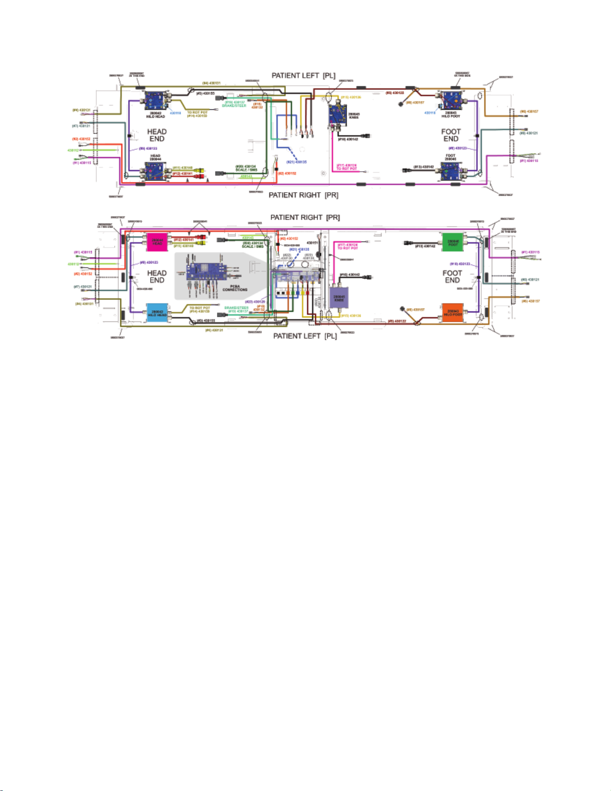
CCaabbllee rroouuttiinngg
5900-009-002 Rev A.0 19 EN
Page 24

MMaaiinntteennaannccee mmeennuu
The maintenance menu provides access to the following settings:
• Language
• Set clock
• Actuator maintenance
• Scale maintenance
• Angle maintenance
• Width maintenance
• Patient station
• Maintenance log
• Clear maintenance log
• Test modes
• Battery maintenance
To access the maintenance menu:
1. On the footboard control panel, press EEnntteerr to access the SSeettttiinnggss menu.
2. Highlight MMaaiinntteennaannccee and press EEnntteerr.
3. Use the up and down arrow buttons to highlight each number.
4. Press EEnntteerr to increase the number.
NNoottee -- The number will increase to 9 until it resets to 0.
5. The maintenance code is as follows: 2, 4, 6
6. Highlight PPrroocceeeedd and press EEnntteerr to access the maintenance menu.
LLaanngguuaaggee
To change the display language:
1. Enter the
2. Highlight LLaanngguuaaggee and press EEnntteerr.
3. Highlight the desired language and press EEnntteerr.
Maintenance menu
(page 20).
SSeett cclloocckk
To change the product clock:
1. Enter the
2. Highlight SSeett cclloocckk and press EEnntteerr.
3. In the clock setting menu you will see the following options:
• Year
• Month
• Day
• Hour
• Minute
4. Use the up and down arrow buttons to highlight each option and press EEnntteerr to set.
Maintenance menu
(page 20).
EN 20 5900-009-002 Rev A.0
Page 25

5. Highlight PPrreessss √√ ttoo sseett and press EEnntteerr to set the product clock.
AAccttuuaattoorr mmaaiinntteennaannccee
CCAAUUTTIIOONN -- Always make sure that the product is clear of obstacles before you use motion functions.
Actuator maintenance allows you to bypass the set limits of the product actuators for testing and troubleshooting.
To access actuator maintenance:
1. Enter the
2. Highlight AAccttuuaattoorr mmaaiinntt.. and press EEnntteerr.
3. In actuator maintenance you will see the following options:
• Both hilos up
• Both hilos down
• Hilo foot up
• Hilo foot down
• Hilo head up
• Hilo head down
• Foot up
• Foot down
• Head up
• Head down
• Knee up
• Knee down
4. Use the up and down arrow buttons to highlight a movement and press and hold EEnntteerr to move the actuator.
Maintenance menu
(page 20).
SSccaallee mmaaiinntteennaannccee
Scale maintenance provides access to the following:
• Gross weight
• Net weight
• Center of gravity
• Load cells foot end
• Load cells head end
• Enable NAWI Scale
• Calibrate scale
To access scale maintenance:
1. Enter the
2. Highlight SSccaallee mmaaiinntt.. and press EEnntteerr.
3. Use the up and down arrow buttons to highlight each number.
4. Press EEnntteerr to increase the number.
NNoottee -- The number will increase to 9 until it resets to 0.
5. The scale maintenance code is as follows: 4, 3, 2
Maintenance menu
(page 20).
5900-009-002 Rev A.0 21 EN
Page 26

6. Highlight PPrroocceeeedd and press EEnntteerr to access scale maintenance.
CCaalliibbrraattee ssccaallee
NNoottee -- Make sure that the product litter deck is flat and horizontal before you calibrate the scale.
TToooollss rreeqquuiirreedd::
• 91 kg (200 lb) calibrated weight
PPrroocceedduurree::
1. Enter the
2. Enter
3. Highlight CCaalliibbrraattee ssccaallee and press EEnntteerr.
4. Remove all weight from the product and press EEnntteerr.
NNoottee -- All weight includes the mattress and accessories.
5. Place the calibrated weight at the head left outer corner and press EEnntteerr.
NNoottee
• Do not touch the product during calibration.
• Make sure that the product is not against a wall during calibration.
6. Place the calibrated weight at the foot left outer corner and press EEnntteerr.
7. Place the calibrated weight at the foot right outer corner and press EEnntteerr.
8. Place the calibrated weight at the head right outer corner and press EEnntteerr.
9. The product screen displays CCoommpplleettee and sends you to the scale maintenance menu when calibration is complete.
Maintenance menu
Scale maintenance
(page 20).
(page 21).
AAnnggllee mmaaiinntteennaannccee
Angle maintenance provides access to the following:
• Foot hilo angle (counts)
• Head hilo angle (counts)
• Foot act position (counts)
• Head act position (counts)
• Knee act position (counts)
• Inclinometer
• Calibrate angles
1. Enter the
2. Highlight AAnnggllee mmaaiinntt.. and press EEnntteerr.
CCaalliibbrraattee aanngglleess
CCAAUUTTIIOONN
• Always calibrate the product angles when you replace the main control board or any actuator or product damage may
occur.
• Always make sure that the product is clear of obstacles before you use motion functions.
Maintenance menu
(page 20).
NNoottee -- Make sure that the product litter deck is flat and horizontal before you calibrate the angles.
Calibrate angles allows you to set the motion limits for the product actuators.
EN 22 5900-009-002 Rev A.0
Page 27

To calibrate the angles:
1. Enter the
2. Enter
3. Highlight CCaalliibbrraattee aanngglleess and press EEnntteerr.
4. Raise the product to high height and press EEnntteerr.
5. Lower the product to low height and press EEnntteerr.
6. Lower the product knee and foot actuators and press EEnntteerr.
7. The product screen displays CCoommpplleettee and sends you to the angle maintenance menu when calibration is complete.
Maintenance menu
Actuator maintenance
(page 20).
(page 21).
WWiiddtthh mmaaiinntteennaannccee
Width maintenance provides access to the following:
• Head State
• Mid State
• Foot State
• Head raw position
• Mid raw position
• Foot raw position
• Calibrate deck widths
• Trim Foot
• Trim Mid
• Trim Head
To access width maintenance:
1. Enter the
2. Highlight WWiiddtthh mmaaiinntt.. and press EEnntteerr.
Maintenance menu
(page 20).
CCaalliibbrraattee ddeecckk wwiiddtthhss
NNoottee -- Make sure that all siderails are in the full up position when you perform this procedure.
To calibrate the deck widths
1. Enter the
2. Enter
3. Highlight CCaalliibbrraattee ddeecckk wwiiddtthhss and press EEnntteerr.
4. Put all decks to the 36” position and press EEnntteerr.
5. Manipulate each siderail and press EEnntteerr.
6. Put all decks to the 42” position and press EEnntteerr.
7. Manipulate each siderail and press EEnntteerr.
8. Put all decks to the 48” position and press EEnntteerr.
9. Manipulate each siderail and press EEnntteerr.
10.The product screen displays CCoommpplleettee and sends you to the width maintenance menu when calibration is complete.
Maintenance menu
Width maintenance
(page 20).
(page 23).
5900-009-002 Rev A.0 23 EN
Page 28

PPaattiieenntt ssttaattiioonn
The patient station menu allows the user to set the product to patient station interface.
Patient station provides access to the following settings:
• Priority call on alarm: a priority call will occur at the nursing station on bed exit alarm
• Nurse call on alarm: a nurse call will occur at the nursing station on bed exit alarm
• Priority call on iBed alertL a priority call will occur at the nursing station on iBed alert
• Cord out relay closed: set the cord out relay
• Audio transfer relay closed: set the audio transfer relay
• Nurse call interlock relay close: set the nurse call interlock relay
• Select nurse call type: select normally open/closed nurse call
To access the patient station settings:
1. Enter the
2. Highlight PPaattiieenntt ssttaattiioonn and press EEnntteerr.
Maintenance menu
(page 20).
TTeesstt mmooddeess
The test mode menu provides access to the following settings:
• Lamp test: turns on all lamps, with either dim or bright backlight
• Siderail display: leaves the siderail angle display on continuously
To access test modes:
1. Enter the
2. Highlight TTeesstt mmooddeess and press EEnntteerr.
Maintenance menu
(page 20).
BBaatttteerryy mmaaiinntteennaannccee
Battery maintenance provides access to the following:
• Charge state
• PMB Bus V
• PMB IIN
• IBAT
• Battery voltage
To access battery maintenance:
1. Enter the
2. Highlight BBaatttteerryy MMaaiinntt.. and press EEnntteerr.
Maintenance menu
(page 20).
EN 24 5900-009-002 Rev A.0
Page 29

SSeerrvviiccee
PPrrootteeccttiinngg aaggaaiinnsstt eelleeccttrroossttaattiicc ddiisscchhaarrggee ((EESSDD))
CCAAUUTTIIOONN
• Always use ESD protective equipment before opening antistatic bags and servicing electronic parts.
• Do not place unprotected circuit boards on the floor.
NNoottee -- Always ship back circuit boards to Stryker in the same antistatic bags that the new boards were originally shipped in.
The electronic circuits in the product are completely protected from static electricity damage when factory assembled.
Always use adequate static protection when servicing the electronic systems of the product. All service personnel must use
static protection whenever they are touching wires.
Sample antistatic protection equipment includes:
• 1 antistatic wrist strap
• 1 grounding plug
• 1 test lead with a banana plug on one end and an alligator clip on the other end
Make sure that you follow the ESD manufacturer’s instructions for appropriate protection against static discharge.
BBaatttteerryy rreeppllaacceemmeenntt
TToooollss rreeqquuiirreedd::
• 5/32” hex driver
• #2 Phillips screwdriver
• 3/8” nut driver
PPrroocceedduurree::
1. Raise the product to the highest height position.
2. On the footboard control panel, press EEnntteerr to access the SSeettttiinnggss menu.
3. Highlight SShhuuttddoowwnn and press EEnntteerr.
4. Unplug the power cord from the wall outlet.
5. Push down on the brake pedal to apply the brake.
6. Using a 5/32” hex driver, remove the two screws and flat washers that secure the motion interrupt pan to the litter
weldment. Remove the motion interrupt pan.
7. Using a #2 Phillips screwdriver, remove the two screws from the power supply mounting bracket closest to the center of
the bed.
8. Using a #2 Phillips screwdriver, remove the two screws from the power supply mounting bracket closest to the outside
of the bed.
9. Hinge the batteries down.
10.Unplug the two battery supply cables from the main control board.
11.Unplug the USB cable from the main control board.
12.Using a 3/8” nut driver, remove the nut that secures the ground cable to the battery mounting plate.
13.Lift up to remove the battery mounting plate assembly from the litter.
14.Reverse steps to reinstall.
15.Verify proper operation of the product before you return it to service.
5900-009-002 Rev A.0 25 EN
Page 30

CCaasstteerr rreeppllaacceemmeenntt
CCAAUUTTIIOONN
• Always perform this procedure in a secure location with the floor jack secure to the base frame before you remove the
caster to prevent the risk of injury.
• Do not put your hands or feet below the caster when you remove or attach the caster to prevent the risk of injury.
TToooollss rreeqquuiirreedd::
• #2 Phillips screwdriver
• Small flat head screwdriver
• 5 mm hex wrench
• Small floor jack
PPrroocceedduurree::
1. On the footboard control panel, press EEnntteerr to access the SSeettttiinnggss menu.
2. Highlight SShhuuttddoowwnn and press EEnntteerr.
3. Unplug the power cord from the wall outlet.
4. Using a small flat head screwdriver, remove and save the four base cover screw caps.
5. Using a #2 Phillips screwdriver, remove and save the four screws that secure the base cover to the base frame.
Remove and save the base cover.
NNoottee -- Set the brakes to the neutral position.
6. Using a small floor jack, raise the base frame high enough to remove the caster.
7. Using a 5 mm hex wrench, remove and save the caster locating screw. Remove and discard the caster.
8. Reverse steps to reinstall.
NNoottee -- The caster stem has a red and green half. Face the red half of the caster stem toward the foot end of the bed.
9. Verify proper operation of the product before you return it to service.
MMaaiinn ccoonnttrrooll bbooaarrdd rreeppllaacceemmeenntt
TToooollss rreeqquuiirreedd::
• 5/32” hex driver
• #2 Phillips screwdriver
• 3/8” nut driver
• ESD system
PPrroocceedduurree::
1. Raise the product to the highest height position.
2. On the footboard control panel, press EEnntteerr to access the SSeettttiinnggss menu.
3. Highlight SShhuuttddoowwnn and press EEnntteerr.
4. Unplug the power cord from the wall outlet.
5. Push down on the brake pedal to apply the brake.
6. Using a 5/32” hex driver, remove the two screws and flat washers that secure the motion interrupt pan to the litter
weldment. Remove the motion interrupt pan.
7. Using a #2 Phillips screwdriver, remove the two screws from the power supply mounting bracket closest to the center of
the bed.
EN 26 5900-009-002 Rev A.0
Page 31

8. Using a #2 Phillips screwdriver, remove the two screws from the power supply mounting bracket closest to the outside
of the bed.
9. Hinge the batteries down.
CCAAUUTTIIOONN
• Always use ESD protective equipment before opening antistatic bags and servicing electronic parts.
• Do not place unprotected circuit boards on the floor.
10.Unplug the two battery supply cables from the main control board.
11.Unplug the USB cable from the main control board.
12.Using a 3/8” nut driver, remove the nut that secures the ground cable to the battery mounting plate.
13.Lift up to remove the battery mounting plate assembly from the litter.
14.Unplug all cables from the main control board. Make note of how the cables are labeled and plugged in.
15.Using a #2 Phillips screwdriver, remove the two screws that secure the main control board assembly to the litter.
16.Grasp the main control board mounting bracket where you removed the two screws and pull down.
17.Reverse steps to reinstall.
18.Verify proper operation of the product before you return it to service.
AAVVBB bbooaarrdd rreeppllaacceemmeenntt
This procedure applies to both the head end and foot end AVB board.
TToooollss rreeqquuiirreedd::
• #2 Phillips screwdriver
• ESD system
PPrroocceedduurree::
1. On the footboard control panel, press EEnntteerr to access the SSeettttiinnggss menu.
2. Highlight SShhuuttddoowwnn and press EEnntteerr.
3. Unplug the power cord from the wall outlet.
4. Push down on the brake pedal to apply the brake.
5. Using a #2 Phillips screwdriver, remove and save the three screws that secure the AVB board assembly to the litter
frame.
6. Remove the AVB board assembly from the litter frame.
CCAAUUTTIIOONN
• Always use ESD protective equipment before opening antistatic bags and servicing electronic parts.
• Do not place unprotected circuit boards on the floor.
7. Disconnect all cables from the AVB board assembly.
8. Using a #2 Phillips screwdriver, remove and save the two screws that secure the beeper to the AVB board assembly.
Remove and save the beeper.
9. Discard the AVB board assembly.
10.Reverse steps to reinstall.
11.Verify proper operation of the product before you return it to service.
5900-009-002 Rev A.0 27 EN
Page 32

FFoooottbbooaarrdd kkeeyyppaadd//ddiissppllaayy rreeppllaacceemmeenntt
TToooollss rreeqquuiirreedd::
• #2 Phillips screwdriver
• Pick
• ESD system
PPrroocceedduurree::
1. On the footboard control panel, press EEnntteerr to access the SSeettttiinnggss menu.
2. Highlight SShhuuttddoowwnn and press EEnntteerr.
3. Unplug the power cord from the wall outlet.
4. Push down on the brake pedal to apply the brake.
5. Using a pick, remove and save the front label from the footboard.
6. Using a #2 Phillips screwdriver, remove the three screws that secure the back panel to the footboard.
7. Remove and save the back panel.
8. Using a #2 Phillips screwdriver, remove and save the six screws and six washers that secure the keypad/display to the
footboard.
CCAAUUTTIIOONN
• Always use ESD protective equipment before opening antistatic bags and servicing electronic parts.
• Do not place unprotected circuit boards on the floor.
9. Disconnect the keypad/display cable. Remove and discard the keypad display.
10.Reverse steps to reinstall.
11.Verify proper operation of the product before you return it to service.
FFoooottbbooaarrdd mmaaiinn ccaabbllee rreeppllaacceemmeenntt
TToooollss rreeqquuiirreedd::
• #2 Phillips screwdriver
• Pick
• ESD system
PPrroocceedduurree::
1. On the footboard control panel, press EEnntteerr to access the SSeettttiinnggss menu.
2. Highlight SShhuuttddoowwnn and press EEnntteerr.
3. Unplug the power cord from the wall outlet.
4. Push down on the brake pedal to apply the brake.
5. Using a pick, remove and save the front label from the footboard.
6. Using a #2 Phillips screwdriver, remove the three screws that secure the back panel to the footboard. Remove and save
the back panel.
7. Using a #2 Phillips screwdriver, remove and save the six screws and six washers that secure the keypad/display to the
footboard.
CCAAUUTTIIOONN
• Always use ESD protective equipment before opening antistatic bags and servicing electronic parts.
• Do not place unprotected circuit boards on the floor.
EN 28 5900-009-002 Rev A.0
Page 33

8. Disconnect the keypad/display cable. Remove and save the keypad display.
9. Remove the footboard from the product.
10.Using a #2 Phillips screwdriver, remove and save the two screws that secure the footboard main cable to the bottom of
the footboard.
11.Remove the footboard main cable from the footboard and discard.
12.Reverse steps to reinstall.
13.Verify proper operation of the product before you return it to service.
FFoowwlleerr aaccttuuaattoorr rreeppllaacceemmeenntt
TToooollss rreeqquuiirreedd::
• Needle nose pliers
• Small flat screwdriver
• Syn-Tech grease (3000-200-719)
PPrroocceedduurree::
1. Raise the product to the highest height position.
2. On the footboard control panel, press EEnntteerr to access the SSeettttiinnggss menu.
3. Highlight SShhuuttddoowwnn and press EEnntteerr.
4. Unplug the power cord from the wall outlet.
5. Push down on the brake pedal to apply the brake.
6. Raise both head end siderails to the up and locked position.
7. Pull the CPR release handle to lower the fowler down.
8. Using needle nose pliers, remove both rue ring retaining clips from the clevis pins that attach the actuator to the litter
weldment and fowler weldment.
9. While supporting the actuator with one hand, remove the head end clevis pin and then lower the actuator down.
NNoottee -- Apply a thin coat of Syn-Tech grease to the clevis pin when you reinstall.
10.Using a small flat screwdriver, unlock the gray CPR pull retainer from the red CPR pull to loosen the CPR pull retainer.
11.Using a small flat screwdriver, remove the gray CPR pull retainer from the red CPR pull. A white spacer between the
CPR pull and the CPR cable retaining bracket will fall out. Save the white spacer.
12.Remove the CPR cables from the CPR cable retaining bracket.
13.Using a small flat screwdriver, release the retaining ring from the power and sensor cable quick connects and
disconnect the cables from the actuator. When re-connecting the cables, fully seat and lock the cable quick connector
retaining ring.
14.While supporting the actuator with one hand, remove the foot end clevis pin and then lower the actuator down.
NNoottee -- Apply a thin coat of Syn-Tech grease to the clevis pin when you reinstall.
15.Reverse steps to reinstall.
16.Verify proper operation of the product before you return it to service.
GGaattcchh aaccttuuaattoorr rreeppllaacceemmeenntt
TToooollss rreeqquuiirreedd::
• Needle nose pliers
• Small flat screwdriver
5900-009-002 Rev A.0 29 EN
Page 34

• Syn-Tech grease (3000-200-719)
PPrroocceedduurree::
1. Raise the product to the highest height position.
2. On the footboard control panel, press EEnntteerr to access the SSeettttiinnggss menu.
3. Highlight SShhuuttddoowwnn and press EEnntteerr.
4. Unplug the power cord from the wall outlet.
5. Push down on the brake pedal to apply the brake.
6. Raise both foot end siderails to the up and locked position.
7. Using a small flat screwdriver, release the power/sensor cable quick connect and disconnect the cable from the
actuator. When re-connecting the cables, fully seat and lock the cable quick connector retaining ring.
8. Using needle nose pliers, remove both rue ring retaining clips from the clevis pins that attach the actuator to the litter
weldment and fowler weldment.
9. While supporting the actuator with one hand, remove the head end clevis pin and foot end clevis pin and then lower the
actuator down.
NNoottee -- Apply a thin coat of Syn-Tech grease to the clevis pin when you reinstall.
10.Reverse steps to reinstall.
11.Verify proper operation of the product before you return it to service.
TThhiigghh aaccttuuaattoorr rreeppllaacceemmeenntt
TToooollss rreeqquuiirreedd::
• Needle nose pliers
• Small flat screwdriver
• Syn-Tech grease (3000-200-719)
PPrroocceedduurree::
1. Raise the product to the highest height position.
2. On the footboard control panel, press EEnntteerr to access the SSeettttiinnggss menu.
3. Highlight SShhuuttddoowwnn and press EEnntteerr.
4. Unplug the power cord from the wall outlet.
5. Push down on the brake pedal to apply the brake.
6. Raise both foot end siderails to the up and locked position.
7. Using needle nose pliers, remove the rue ring retaining clip from the head end clevis pin that attaches the actuator to the
litter weldment.
8. Using needle nose pliers, remove the circle ring retaining ring from the foot end clevis pin that attaches the actuator to
the thigh weldment.
9. While supporting the actuator with one hand, remove the head end clevis pin and the foot end clevis pin and then lower
the actuator down.
NNoottee -- Apply a thin coat of Syn-Tech grease to the clevis pin when you reinstall.
10.Using a small flat screwdriver, release the power/sensor cable quick connect and disconnect the cable from the
actuator. When re-connecting the cables, fully seat and lock the cable quick connector retaining ring.
11.Reverse steps to reinstall.
NNoottee -- Route the power/sensor cable over the top of the actuator when you reinstall the actuator.
12.Verify proper operation of the product before you return it to service.
EN 30 5900-009-002 Rev A.0
Page 35

LLiifftt aaccttuuaattoorr rreeppllaacceemmeenntt ((hheeaadd//ffoooott))
TToooollss rreeqquuiirreedd::
• Needle nose pliers
• (2) 3/8” x 1” grade 8 bolt and nut
• Syn-Tech grease (3000-200-719)
PPrroocceedduurree::
1. Run the actuator up or down to remove the litter load from the actuator.
2. Raise both siderails to the up and locked position at either the head end or foot end.
3. If the activator still runs:
a. Raise the product to the highest height position to expose the base weldment support holds on both sides.
CCAAUUTTIIOONN -- Always leave the bolts loose in the support holes, so the bolt head is out far enough to stop the lift
mechanism slide block.
b. Insert two 3/8” bolts through the support holes in the base weldment from the inside out and then thread the nuts
onto the bolts to keep the bolts from falling out.
WWAARRNNIINNGG -- Do not lower the litter too low or the litter may not be supported.
c. Lower the litter until the lift mechanism slides touch the 3/8” bolt heads. You should be able to wiggle the actuator by
hand after you remove the litter load from the litter surface. If not, lower the litter more until the actuator is loose.
4. If the activator does not run:
a. Put the bed into the Maintenance mode (limits bypassed) and then go to the Actuator Maintenance Menu. Select the
actuator that needs to be moved and see if it will run.
b. See step 2a.
5. If the actuator will not run with the limits bypassed in step 4a, use a hoist, with a strap around and under the litter, to
remove the litter load from the actuator and support the litter surface on the end that has failed.
6. On the footboard control panel, press EEnntteerr to access the SSeettttiinnggss menu.
7. Highlight SShhuuttddoowwnn and press EEnntteerr.
8. Unplug the power cord from the wall outlet.
9. Using the cable quick connector release, unlock the cable from the motor control box so that it is loose.
10.Using needle nose pliers, remove both rue ring retaining clips from the clevis pins that attach the actuator to the litter
weldment and lift weldment.
11.While supporting the actuator with one hand, remove the head end clevis pin and foot end clevis pin and then lower the
actuator down.
NNoottee -- Apply a thin coat of Syn-Tech grease to the clevis pin when you reinstall.
12.Reverse steps to reinstall.
13.Verify proper operation of the product before you return it to service.
LLooaadd cceellll bbooaarrdd rreeppllaacceemmeenntt,, hheeaadd eenndd aanndd ffoooott eenndd
TToooollss rreeqquuiirreedd::
• #2 Phillips screwdriver
• Small flat head screwdriver
• ESD system
5900-009-002 Rev A.0 31 EN
Page 36

PPrroocceedduurree::
1. Push down on the brake pedal to apply the brake.
2. On the footboard control panel, press EEnntteerr to access the SSeettttiinnggss menu.
3. Highlight SShhuuttddoowwnn and press EEnntteerr.
4. Unplug the power cord from the wall outlet.
5. Using a small flat head screwdriver, remove and save the four base cover screw caps.
6. Using a #2 Phillips screwdriver, remove and save the four screws that secure the base cover to the base frame.
Remove and save the base cover.
7. Using a #2 Phillips screwdriver, remove and save the two screws that secure the load cell board assembly to the base
weldment. Remove the load cell board assembly.
CCAAUUTTIIOONN
• Always use ESD protective equipment before opening antistatic bags and servicing electronic parts.
• Do not place unprotected circuit boards on the floor.
8. Disconnect the communication cable and the two load cells from the load cell board assembly. Discard the load cell
board assembly.
9. Reverse steps to reinstall.
10.Recalibrate the scale (
11.Verify proper operation of the product before you return it to service.
Calibrate scale
(page 22)).
LLooaadd cceellll aasssseemmbbllyy rreeppllaacceemmeenntt
TToooollss rreeqquuiirreedd::
• #2 Phillips screwdriver
• Small flat head screwdriver
• Needle nose pliers
• Ratchet
• 1/2” socket
• Small floor jack
PPrroocceedduurree::
1. Push down the brake pedal to apply the brake.
2. On the footboard control panel, press EEnntteerr to access the SSeettttiinnggss menu.
3. Highlight SShhuuttddoowwnn and press EEnntteerr.
4. Unplug the power cord from the wall outlet.
5. Using a small flat head screwdriver, remove and save the four base cover screw caps.
6. Using a #2 Phillips screwdriver, remove and save the four screws that secure the base cover to the base frame
weldment. Remove and save the base cover.
7. Using a small floor jack, near the load cell that you need to replace, push downward on the jack’s lever to raise the lift
support tube upward.
8. Using needle nose pliers. remove and save the rue clip and pin from the base frame weldment.
9. Using a ratchet and 1/2” socket, remove and save the two bolts that secure the load cell assembly to the base frame
weldment..
NNoottee -- When you reinstall the load cell assembly, orient the load cell assembly up, so you can secure the bolts by hand
to start.
10.Using needle nose pliers, remove the load cell assembly from the base frame weldment.
EN 32 5900-009-002 Rev A.0
Page 37

11.Using a #2 Phillips screwdriver, remove and save the two screws that secure the inspection cover to the base frame
weldment. Remove and save the inspection cover.
12.Using a #2 Phillips screwdriver, remove and save the two screws that secure the board assembly to the base frame
weldment. Remove and save the board assembly.
13.Disconnect the load cell assembly and remove the cable from the base frame weldment. Discard the load cell assembly.
NNoottee -- Note the routing of the load cell cable for reinstallation.
14.Reverse steps to reinstall.
15.Recalibrate the scale (
16.Verify proper operation of the product before you return it to service.
Calibrate scale
(page 22)).
SSiiddeerraaiill rreeppllaacceemmeenntt,, hheeaadd eenndd
TToooollss rreeqquuiirreedd::
• T15 Torx driver
• T27 Torx driver
• Needle nose pliers
• Syn-Tech grease (3000-200-719)
PPrroocceedduurree::
1. Raise the product to the highest height position.
2. Raise the Fowler to the full upright position.
3. On the footboard control panel, press EEnntteerr to access the SSeettttiinnggss menu.
4. Highlight SShhuuttddoowwnn and press EEnntteerr.
5. Unplug the power cord from the wall outlet.
6. Push down on the brake pedal to apply the brake.
7. Expand all litter decks to the 48 in. position.
8. Raise the siderail to the up and locked position.
9. Using a T15 Torx driver, remove the two screws that secure the junction board assembly to the siderail carrier. Remove
the junction board assembly.
10.Unplug the two siderail cables from the junction board assembly.
11.Using a T27 Torx driver, remove the screw that secures the guide rod to the litter.
12.Push the siderail release button to lower the siderail to the lowest stowed position.
13.Using needle nose pliers, from under the litter surface, slide each glide rod out.
NNoottee -- Save the two rubber washers on each glide rod, one on both sides of the siderail carrier, to reinstall. Use SynTech grease to lube the glide rod, if required.
14.While supporting the rail with one hand, remove both glide rods and remove the siderail assembly.
15.Reverse steps to reinstall.
16.Verify proper operation of the product before you return it to service.
SSiiddeerraaiill rreeppllaacceemmeenntt,, ffoooott eenndd
TToooollss rreeqquuiirreedd::
• T15 Torx driver
• T27 Torx driver
5900-009-002 Rev A.0 33 EN
Page 38

• Needle nose pliers
• Syn-Tech grease (3000-200-719)
PPrroocceedduurree::
1. Raise the product to the highest height position.
2. On the footboard control panel, press EEnntteerr to access the SSeettttiinnggss menu.
3. Highlight SShhuuttddoowwnn and press EEnntteerr.
4. Unplug the power cord from the wall outlet.
5. Push down on the brake pedal to apply the brake.
6. Expand all litter decks to the 48 in. position.
7. Raise the siderail to the up and locked position.
8. Using a T15 Torx driver, remove the two screws that secure the junction board assembly to the siderail carrier. Remove
the junction board assembly.
9. Unplug the two siderail cables from the junction board assembly.
10.Using a T27 Torx driver, remove the screw that secures the guide rod to the litter.
11.Push the siderail release button to lower the siderail to the lowest stowed position.
12.Using needle nose pliers, from under the litter surface, slide each glide rod out.
NNoottee -- Save the two rubber washers on each glide rod, one on both sides of the siderail carrier, to reinstall. Use SynTech grease to lube the glide rod, if required.
13.While supporting the rail with one hand, remove both glide rods and remove the siderail assembly.
14.Reverse steps to reinstall.
15.Verify proper operation of the product before you return it to service.
IIVV ppoollee aattttaacchhmmeenntt
TToooollss rreeqquuiirreedd::
• 3/8” ratchet
• 3/16” hex driver
• 1/2” socket
• 9/16” socket
PPrroocceedduurree::
1. Using a 3/16” hex driver, remove and save the power cord retainer shoulder bolt and strap on both sides of the product.
2. Using a 1/2” socket, secure the bracket with the IV pole assembly to the left side of the product with the two supplied
bolts and washers.
3. Using a 1/2” socket, secure the bracket with the rest block to the right side of the product with the two supplied bolts and
washers.
4. Using a 3/16” hex driver, secure the power cord retainer shoulder bolt and strap on both sides of the product through
both brackets.
5. Verify proper operation of the product before you return it to service.
PPaattiieenntt hheellppeerr aattttaacchhmmeenntt
TToooollss rreeqquuiirreedd::
• 3/8” ratchet
EN 34 5900-009-002 Rev A.0
Page 39

• 3/8” hex driver
• 7/16” socket
PPrroocceedduurree::
1. Using a 3/8” hex driver, attach the patient helper mounting bracket with the four supplied screws.
NNoottee -- Make sure that the armrest pin faces upward.
2. On the floor, place the patient helper lifting pole, patient helper cap, and patient helper trapeze hanger together.
3. Using a 7/16” socket, secure the patient helper lifting pole, patient helper cap, and trapeze hanger together with the
supplied bolt.
4. With another person, lift and insert the patient helper assembly into the patient helper mounting bracket.
5. Verify proper operation of the product before you return it to service.
5900-009-002 Rev A.0 35 EN
Page 40

TToopp lleevveell aasssseemmbbllyy
10
4
2X
5
2X
7
2X
TORQUE TO
150-180in/lbs
5
2X
4
2X
6
2X
14
2X
15
2X
TORQUE TO
150-180in/lbs
TORQUE TO
150-180in/lbs
11
16
2X
9
2X
17
3
2X
2
2X
NOTE ORIENTATION OF SLIDE BLOCKS
(COUNTERBORE HOLES FACE OUTWARD)
TORQUE TO
215-235in/lbs
TORQUE TO
50-70in/lbs
50
45
50
45
44
TORQUE TO
50-70in/lbs
5900103001 Rev G (Reference only)
EN 36 5900-009-002 Rev A.0
Page 41
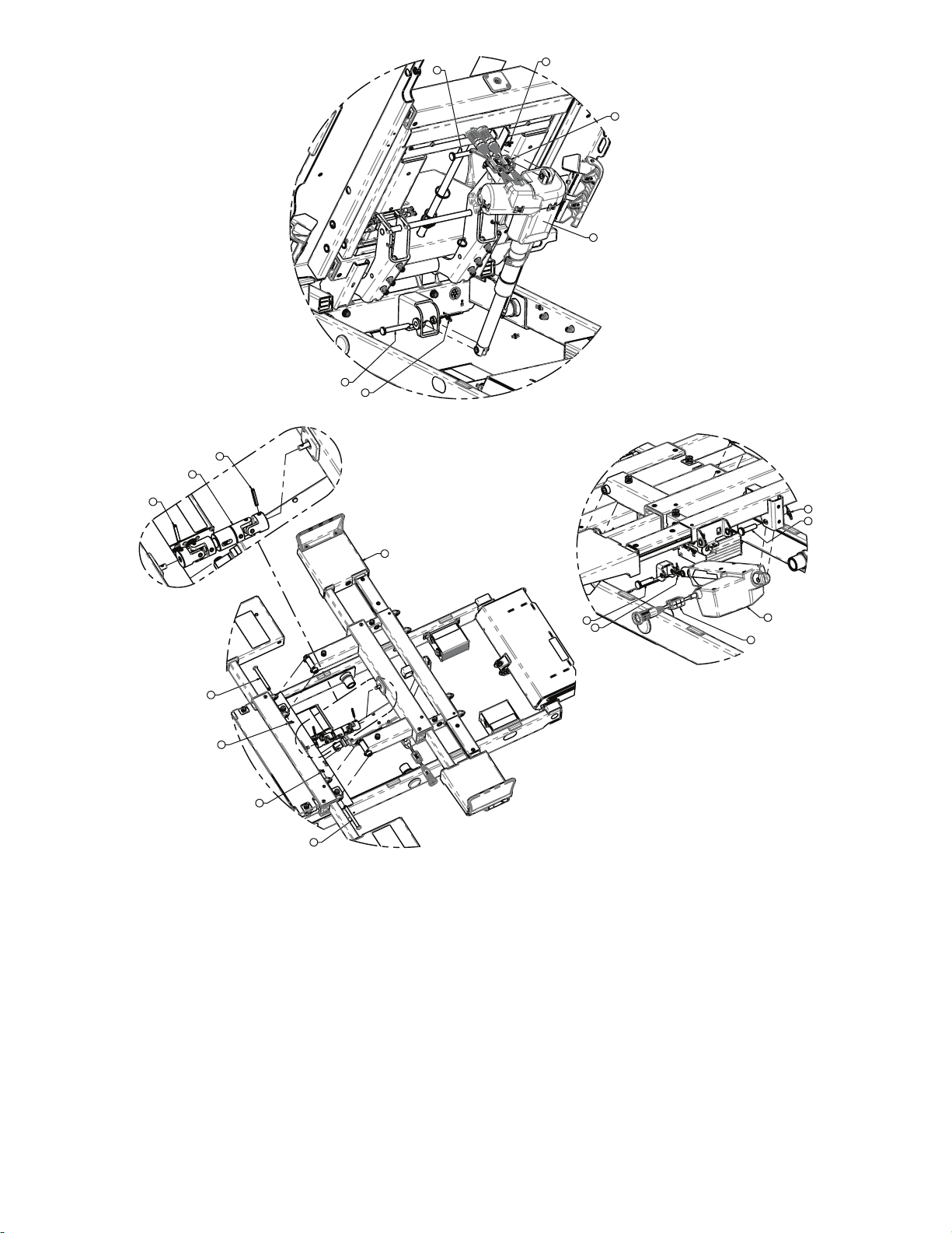
20
9
19
18
9
51
2X
8
9
12
9
8
46
51
21
9
9
21
42
42
43
5900-009-002 Rev A.0 37 EN
Page 42

8
9
9
8
41
38
3X
39
3X
38
3X
37
40
39
3X
37
13
TORQUE TO
50-70in/lbs
TORQUE TO
50-70in/lbs
35
9
21
51
18
36
33
31
32
34
25
2X
24
26
8X
28
8X
27
8X
29
8X
30
8X
TORQUE TO
70-90in/lbs
EN 38 5900-009-002 Rev A.0
Page 43

22
23
49
2X
48
2X
IItteemm NNuummbbeerr NNaammee QQuuaannttiittyy
1 5900200119 Hi-low frame assembly 1
2 5900340082 Screw, shldr 1/2 x 2.00 - 3/8 UNC
2
locking patch
3 5900600073 Slide block, fowler & vascular 2
4 0011-003-000 Washer, plain 5/16 x 0.688 AP 4
5 0012-020-000 Washer, lock reg 5/16 4
6 5900340106 Screw, hex head 5/16-UNC x 2.00LG
2
GR8
7 5900340107 Screw, hex head 5/16-UNC x 1.25”LG
2
GR8
8 5900350036 Pin, clevis 3/8"DIA x 3.75"LG (3.5" U/L)
4
zinc
9 0027-022-000 Rue ring, 3/8" 11
10 5900200041 Deck assembly, seat section 1
11 5900200055 Deck assembly, head section 1
12 5900200056 Deck assembly, knee section 1
13 5900200057 Deck assembly, foot section 1
14 0008-031-000 Screw, shldr 3/8 x 2.25 - 5/16-UNC 2
15 0016-036-000 Nut, nylok 5/16-UNC 2
16 5900350049 Pin, clevis 3/8"dia x 3.25"LG (3.00" U/L)
2
zinc
17 5900200137 Link assembly, Fowler regression S1 1
18 5900350035 Pin, clevis 10mm x 50mm (44mm U/L)
zinc
19 5900350044 Pin, clevis 10mm x 70mm (64mm U/L)
2
1
zinc
20 5900200157 Actuator assembly, S1 head w/CPR
1
release
21 5900350046 Pin, clevis 10mm x 40mm (34mm U/L)
22 5900200026 Exp headboard assembly 1
zinc
3
23 5900200025 Footboard assembly 1
24 5900200158 Wire guide assembly, expandable deck 4
25 5900340055 Screw, plastite pan head Torx 10-14 x
8
1" LG zinc
26 5900500022 Pin, rail arm bracket slide 8
5900-009-002 Rev A.0 39 EN
Page 44

IItteemm NNuummbbeerr NNaammee QQuuaannttiittyy
27 5900320016 Washer, EPDM rubber 0.49ID x
8
1.063OD x 0.093W
28 5900370042 O-ring, AS568A-206 BUNA-N
8
(0.484IDx0.762oDx0.139W)
29 5900320028 Washer, plain #12 x 0.562 AP 8
30 0004-592-000 Screw, BH Torx 1/4-UNC x 0.75 8
31 5900200130 Rail assembly, patient right, head 1
32 5900200131 Rail assembly, patient left, head 1
33 5900200132 Rail assembly, patient right, foot 1
34 5900200133 Rail assembly, patient left, foot 1
35 5900420011 Actuator, foot 1
36 5900370106 Cotterpin, 3/4" circle 1
37 5900320029 Washer, flat 1/2 x 1-1/4 x 0.063 nylon 2
38 0005-017-000 Bolt, carriage 1/4 - UNC 3/4 LG zinc 6
39 0016-102-000 Nut, thin hex nylock 1/4-20-UNC zinc
6
GR2
40 5900240108 Gatch arm weldment, foot bail, patient
1
right
41 5900240109 Gatch arm weldment, foot bail, patient
1
left
42 0026-012-000 Pin, spring 3/16" x 1.25"LG blk OX 2
43 5900200138 U-joint, sliding expandable deck 1
44 5900430143 HRNS, GND braid D 1
45 5900340079 Screw, #10-32 x 1/2LG hex washer
2
head elec ground
46 5900420012 Actuator, knee 1
47 5900350047 Lock ring, linak mini-fit connector 4
48 5900500160 Post, cord strap fastener 2
49 8001-000-171 Strap, cord/hose management 2
50 5900520247 Clip, ground strap anti rotate ring 2
51 5900410059 Ferrite, split, snap-on WURTH 0.138''-
4
0.197'' cable
53 3000-300-113 Cable tie, nylon 8” LG 10
EN 40 5900-009-002 Rev A.0
Page 45

UUppppeerr ffrraammee aasssseemmbbllyy
1
20
21
23
22
24
13
14
5900200120 Rev E (Reference only)
5900-009-002 Rev A.0 41 EN
Page 46

20
21
23
22
24
DETAIL A
17
2X / BOX
2
2X / BOX
DETAIL B
9
4X
10
8X
4
2X
3
2X
EN 42 5900-009-002 Rev A.0
Page 47

DETAIL C
17
2X
18
2X
2
2X
10
6X
DETAIL D
19
3X
7
6
5
6
6
5
5900-009-002 Rev A.0 43 EN
Page 48

13
17
4X
27
2X
28
2X
2
4X
DETAIL E
2
18
17
14
17
4X
17
2X
15
16
2
6X
27
2X
28
2X
2
17
25
26
3X
12
11
Torque item 11
to 50-70 in-lb
EN 44 5900-009-002 Rev A.0
Page 49
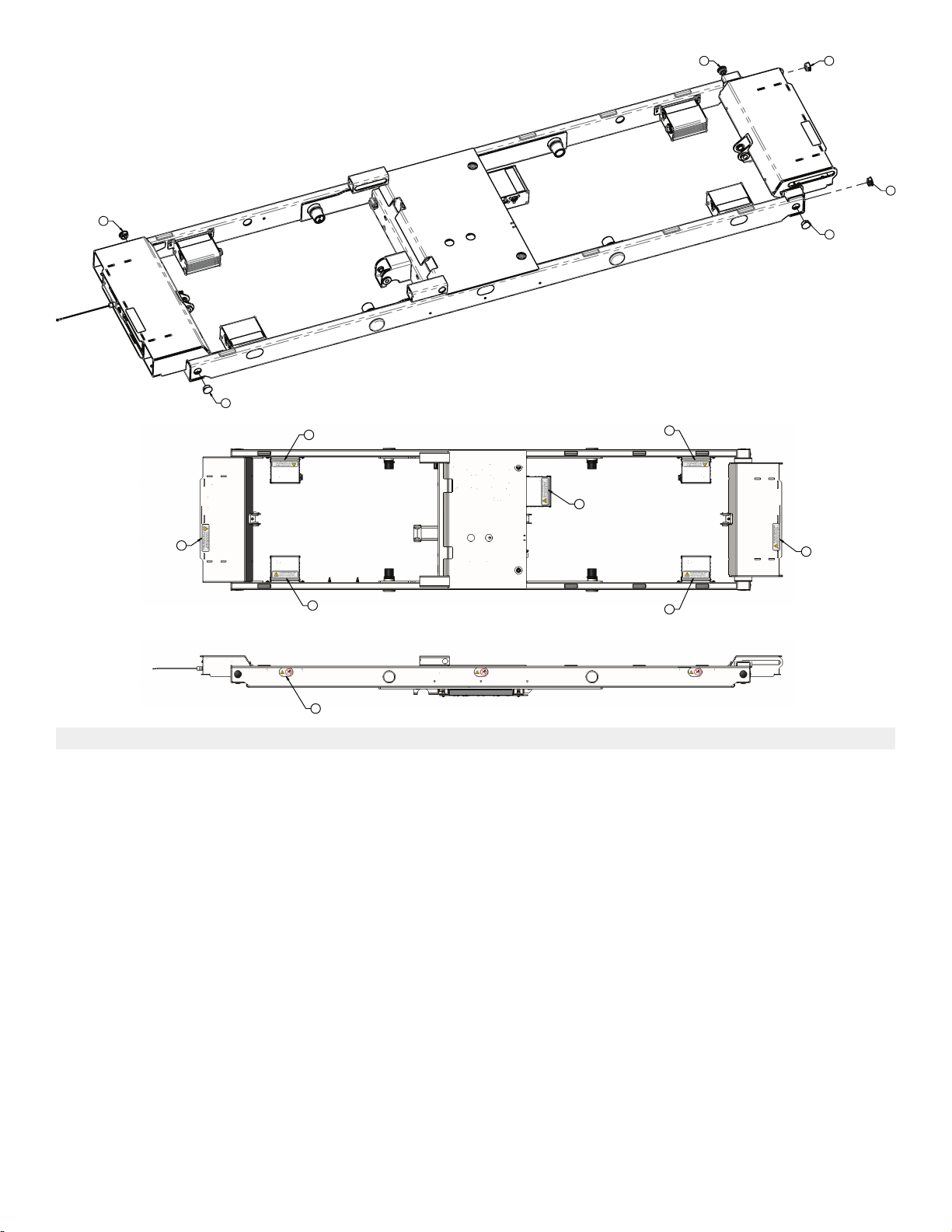
8
8
88
8
8
50
6X
51
51
51
51
51
51
51
IItteemm NNuummbbeerr NNaammee QQuuaannttiittyy
1 5900240094 Upper frame weldment 1
2 5900310020 Nutsert, #10-UNF thick sheet hex body-
25
zinc
3 5900310007 Nutsert, 1/4-UNC hex body 2
4 5900310025 Nutsert, 5/16-UNC hex body 2
5 5900370023 Grommet, push-in split expandable 1”
hole
6 5900370075 Grommet, push-in locking 3/4” 3
7 5900350051 Strain relief, snap-in ratcheting Ø0.12-
2
1
0.75
8 5900370037 Plug, push-in round plastic 7/8” 6
9 5900330021 Bushing, flg 1.000X1.250X1.250LG (flg
4
1.500X0.188)
10 5900600067 Bumper pad, snap-in hard stop 14
11 5900340079 Screw, #10-32 x 1/2LG hex washer head
12 5900430112 HRNS, gnd braid C 1
elec ground
1
13 5900280026 Electrical assembly, AC power 1
14 5900280025 Electrical assembly, DC power 1
15 5900280051 Electrical assembly, main power/control 1
5900-009-002 Rev A.0 45 EN
Page 50

IItteemm NNuummbbeerr NNaammee QQuuaannttiittyy
16 5900200164 ASM, HRNS support span 1
17 5900340090 Screw, sems pan PH #10-32UNF x 3/
25
4LG int wash zinc
18 0034-020-000 P-clamp, 3/8” insulated 3
19 5900350041 Cable tie, fir tree mount 1mm-35mm
3
bundle blk
20 5900280042 Electrical assembly, IOM ACB-EHA
1
head lift
21 5900280044 Electrical assembly, IOM ACB-head
1
deck
22 5900280043 Electrical assembly, IOM ACB-EHA foot
1
lift
23 5900280045 Electrical assembly, IOM ACB-knee
1
deck
24 5900280046 Electrical assembly, IOM ACB-foot deck 1
25 5900280033 Electrical assembly, DB37 1
26 5900340071 Screw, sems pan ph #6-32X3/8LG int
3
wash zinc PL
27 5900410030 Switch, SPDT-N/O-N/C omron D3D-211 4
28 5900520237 Bracket, obstruction sensor switch plate 4
29 5900410030 HRNS, PS output TDK XMS series 1
30 5900430152 HRNS, PS input TDK XMS series 1
31 5900430115 HRNS, AC supply aux 1
32 5900430122 HRNS, primary act pwr-comm A 1
33 5900430155 HRNS, primary act pwr-comm B 1
34 5900430123 HRNS, secondary act pwr-comm 2
35 5900430136 HRNS, act knee pwr-comm 1
36 5900430121 HRNS, NC-AV pwr comm 2
37 5900430135 HRNS, pwr-comm MCU to JCTN seat 1
38 5900430132 HRNS, pwr-comm MCU to JCTN 1
39 5900430142 HRNS, act knee-foot LA31 2
40 5900430124 HRNS, act feedback (long) 1
41 5900430159 HRNS, act feedback 1
42 5900430140 HRNS, act head LA34 1
43 5900430141 HRNS, act head CPR 1
44 5900430131 HRNS, NC-SPKR PSI to JCTN 1
45 5900430134 HRNS, scale pwr-comm 1
46 5900430137 HRNS, brake-steer detect 1
47 5900430130 HRNS, underbed obstruction (short) 3
48 5900430129 HRNS, underbed obstruction (long) 1
49 5900430157 HRNS, DPM patch cable 1
50 5900180108 Label, no drilling 6
51 5900180098 Label, electrical shock warning 7
EN 46 5900-009-002 Rev A.0
Page 51
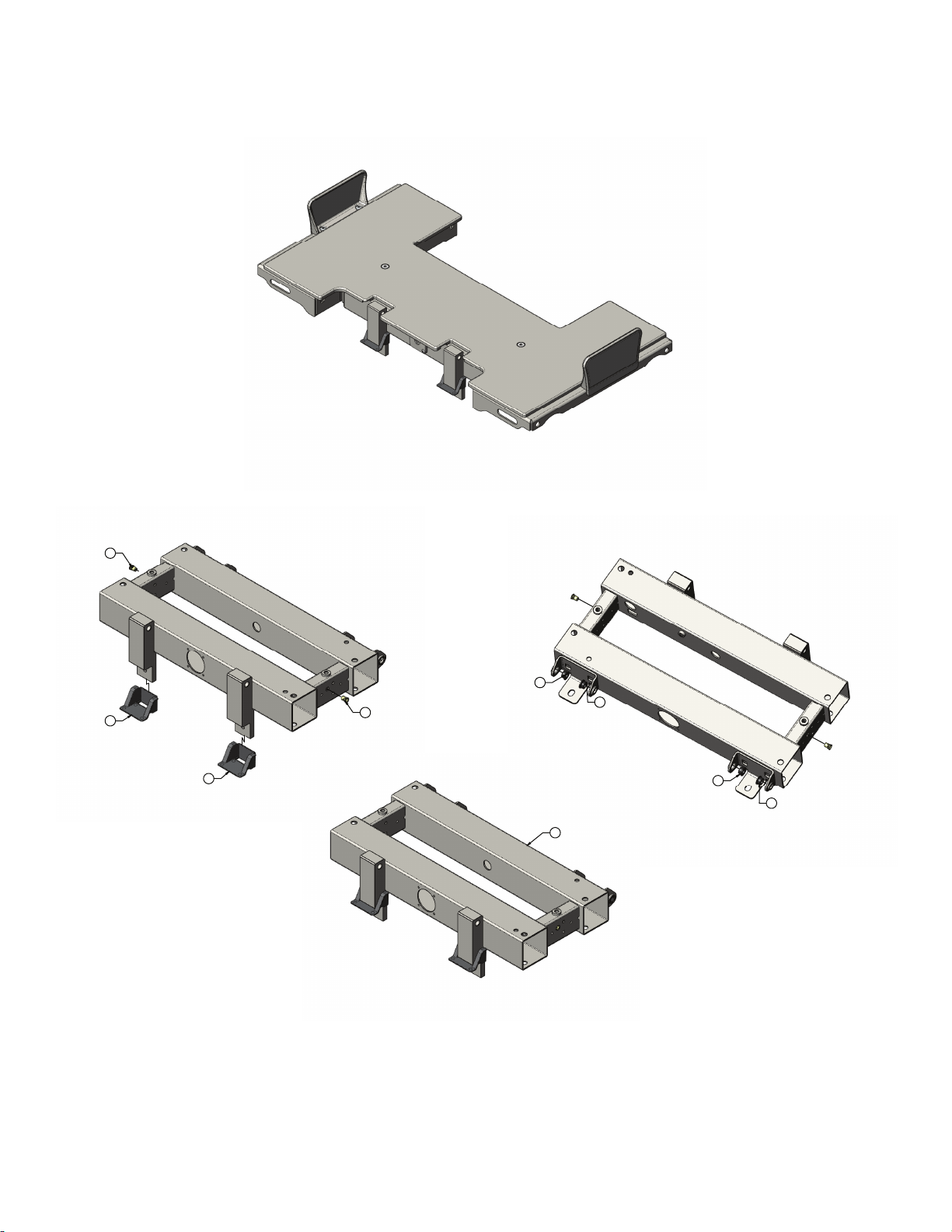
DDeecckk aasssseemmbbllyy,, sseeaatt sseeccttiioonn
22
22
12
12
21
21
21
21
1
5900200041 Rev E (Reference only)
5900-009-002 Rev A.0 47 EN
Page 52

2
3
13
13
13
13
13
13
13
13
13
14 14
4
6
6
56
6
4
14
14
Torque item 14
to 25-30 in-lb
Torque item 14
to 25-30 in-lb
EN 48 5900-009-002 Rev A.0
Page 53

16
16
10
10
11
24
19
20
25
5900-009-002 Rev A.0 49 EN
Page 54
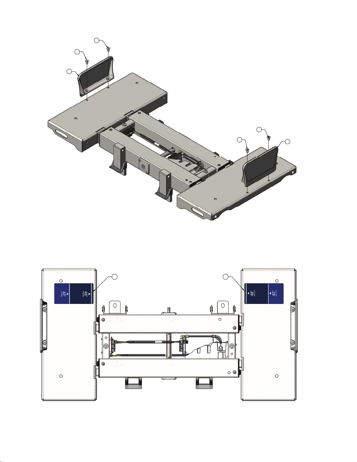
18
18
18
18
17
17
2323
EN 50 5900-009-002 Rev A.0
Page 55

7
15
15
15
7
5900-009-002 Rev A.0 51 EN
Page 56
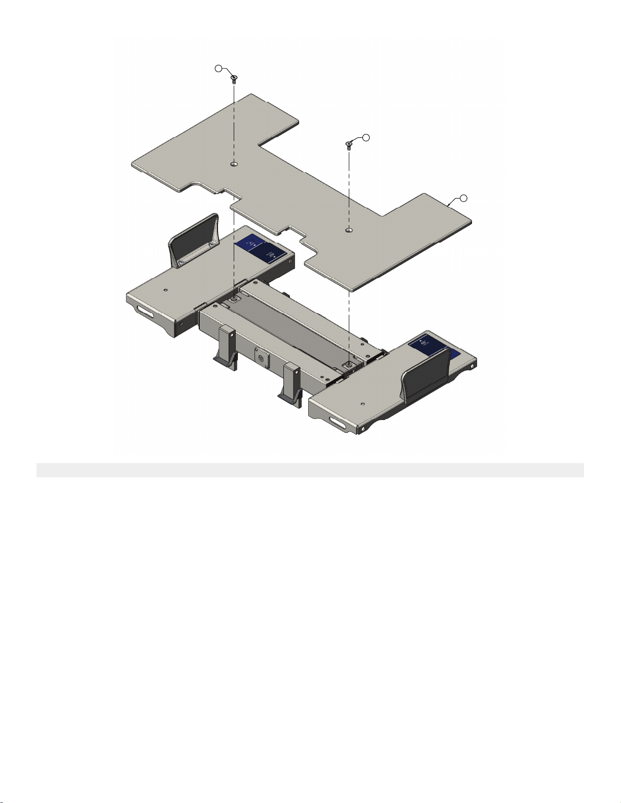
9
9
8
IItteemm NNuummbbeerr NNaammee QQuuaannttiittyy
1 5900240025 Frame weldment, seat deck 1
2 5900200038 Deck pan assembly, seat deck, patient
1
right
3 5900200039 Deck pan assembly, seat deck, patient
1
left
4 5900600007 Bushing, pinion shaft cover 2
5 5900500027 Pinion shaft, seat deck 1
6 5900560003 Pinion gear, expandable deck 4
7 5900520200P Cover pan, seat deck plated 1
8 5900620005 Cover, seat deck 1
9 5900340081 Screw, flat hex head 5/16-18x3/4lg zinc 2
10 5900340105 Screw, plastite pan head Torx #8-16 x
2
1.25"LG zinc
11 5900340101 Screw, RD HD FLG hex drive 1/4-UNC x
1
3/8LG zinc
12 5900310020 Nutsert, #10-unf thick sheet hex body -
2
zinc
13 5900340114 Screw, plastite pan head PH #10-14 x 1/
8
2" LG ZNPL
14 5900340017 Screw, pan PH #8-UNC x 0.3125 4
15 5900340090 Screw, sems pan PH #10-32UNF x 3/
2
4LG INT wash zinc
EN 52 5900-009-002 Rev A.0
Page 57

IItteemm NNuummbbeerr NNaammee QQuuaannttiittyy
16 5900340097 Screw, sems pan PH #6-32x1-1/2LG
2
INT wash zinc PL
17 5900600035 Mattress keeper, short 2
18 0025-120-000 Rivet, 1/4 x 0.600" LG blind alum 4
19 5900400051 PCBA, s1 jctn hd/ft pl-in/pr-out 1
20 5900280016 Elec assembly, jctn seat in-bd backplate 1
21 5900330003 Bushing, flg 0.375x0.500x0.313lg (flg
4
0.625x0.062)
22 5900600076 Guard, seat deck mounts gap filler 2
23 5900690076 Label, indicator deck width 2
24 5900430144 HRNS, jctn pwr-comm int mid 1
25 5900200152 Lock assembly, seat deck position 1
5900-009-002 Rev A.0 53 EN
Page 58

DDeecckk ppaann aasssseemmbbllyy,, sseeaatt ddeecckk,, ppaattiieenntt rriigghhtt
3
2X
4
4X
1
2X
7
6
4X
5
4X
2
6
4X
5900200038 Rev A (Reference only)
IItteemm NNuummbbeerr NNaammee QQuuaannttiittyy
1 5900560011 Rack, expandable deck 2
2 5900240029 Pan weldment, seat deck, patient right 1
3 5900600006 Bearing, expandable deck guide 2
4 5900600034 Roller, expandable deck 4
5 5900500028 Pin, expandable deck roller 4
6 0025-079-000 Rivet, 3/16 domed SST 8
7 5900690050 Decal, deck lock position sensor 1
EN 54 5900-009-002 Rev A.0
Page 59
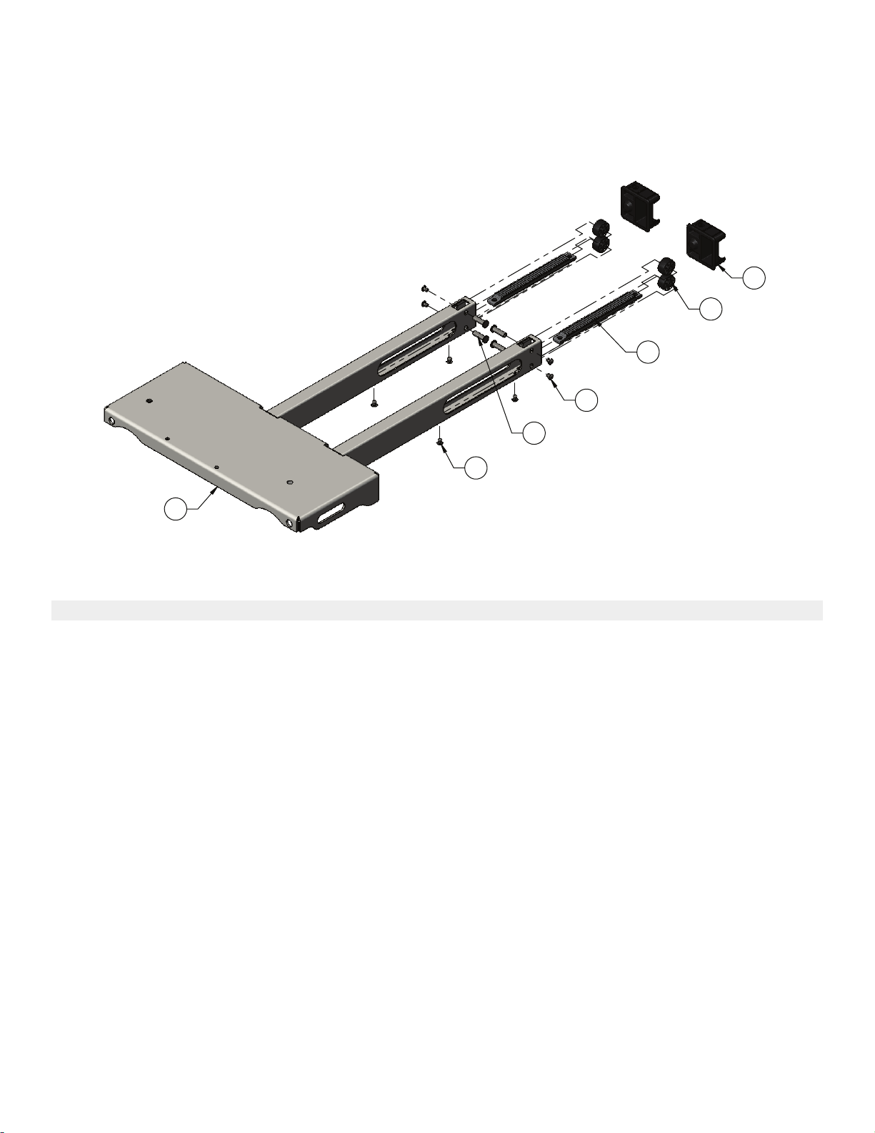
DDeecckk ppaann aasssseemmbbllyy,, sseeaatt ddeecckk,, ppaattiieenntt lleefftt
3
2X
4
4X
6
X
1
2X
5
4X
6
4X
2
5900200039 Rev A (Reference only)
IItteemm NNuummbbeerr NNaammee QQuuaannttiittyy
1 5900560011 Rack, expandable deck 2
2 5900240030 Pan weldment, seat deck, patient left 1
3 5900600006 Bearing, expandable deck guide 2
4 5900600034 Roller, expandable deck 4
5 5900500028 Pin, expandable deck roller 4
6 0025-079-000 Rivet, 3/16 domed SST 8
5900-009-002 Rev A.0 55 EN
Page 60

DDeecckk aasssseemmbbllyy,, hheeaadd sseeccttiioonn
14
14
11
11
11
11
11
11
11
11
27
27
27
27
14
14
1
15
15
15
15
15
15
15
15
2
3
15
5900200055 Rev E (Reference only)
EN 56 5900-009-002 Rev A.0
Page 61

4
6
6
16
16
5
6
6
16
16
4
Torque item 16
to 25-30 in-lb
Torque item 16
to 25-30 in-lb
13
12
12
7
5900-009-002 Rev A.0 57 EN
Page 62
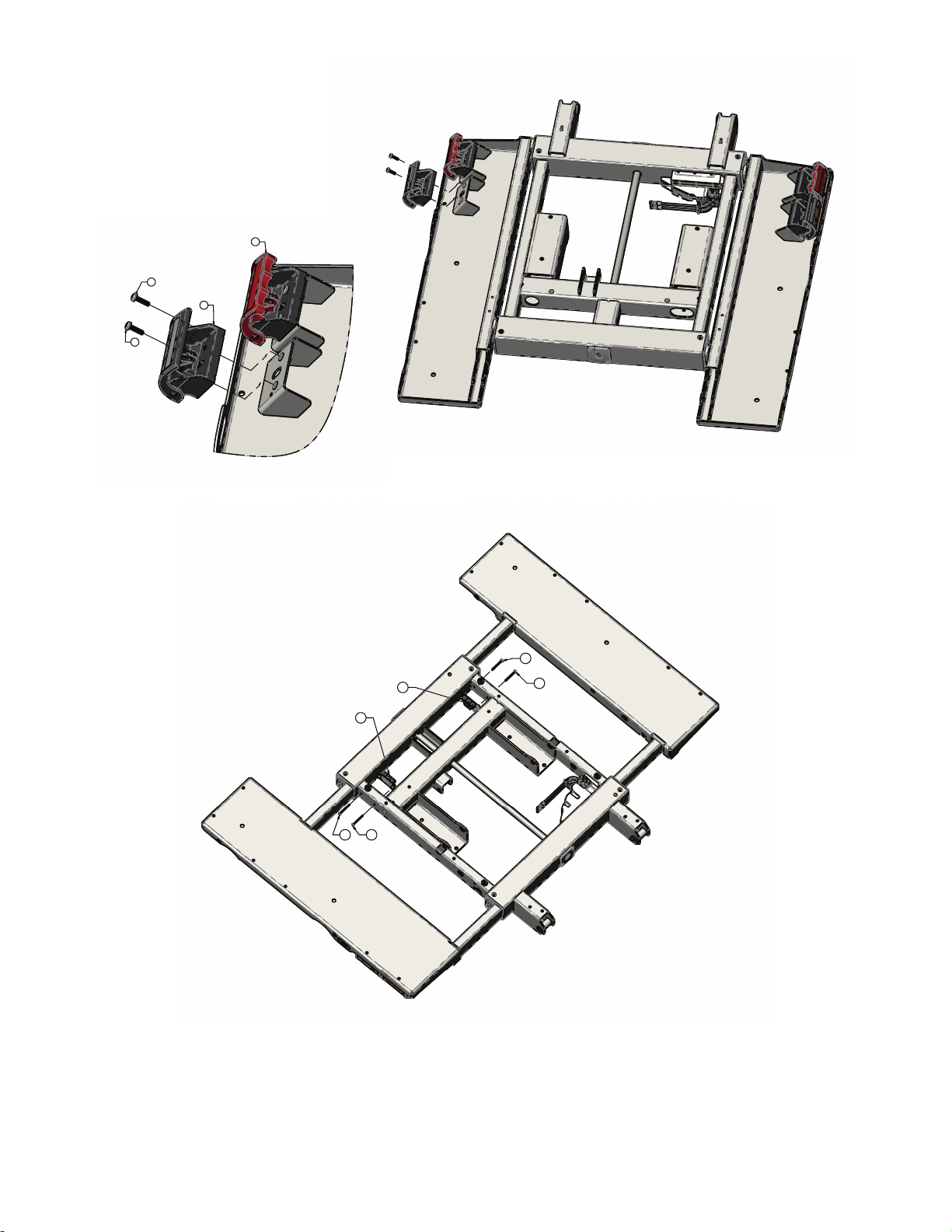
17
17
23
24
21
20
2222
22
22
EN 58 5900-009-002 Rev A.0
Page 63

8
17
17
17
17
30
29
9
17
17
18
19
19
5900-009-002 Rev A.0 59 EN
Page 64

12.75±0.125
2x
1.75±0.125
2x
28
28
EN 60 5900-009-002 Rev A.0
Page 65

28
28
32
32
5900-009-002 Rev A.0 61 EN
Page 66
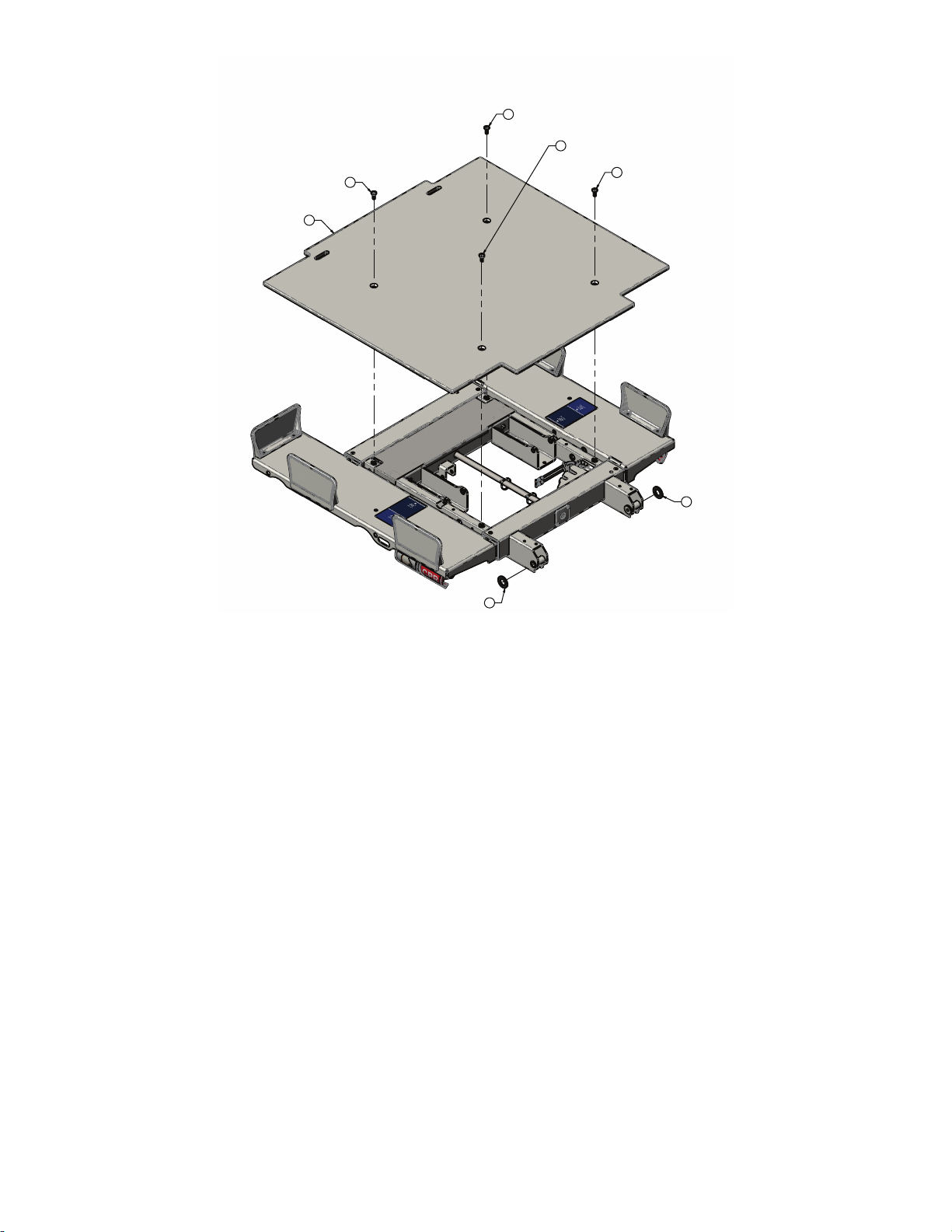
26
26
26
26
10
25
25
EN 62 5900-009-002 Rev A.0
Page 67
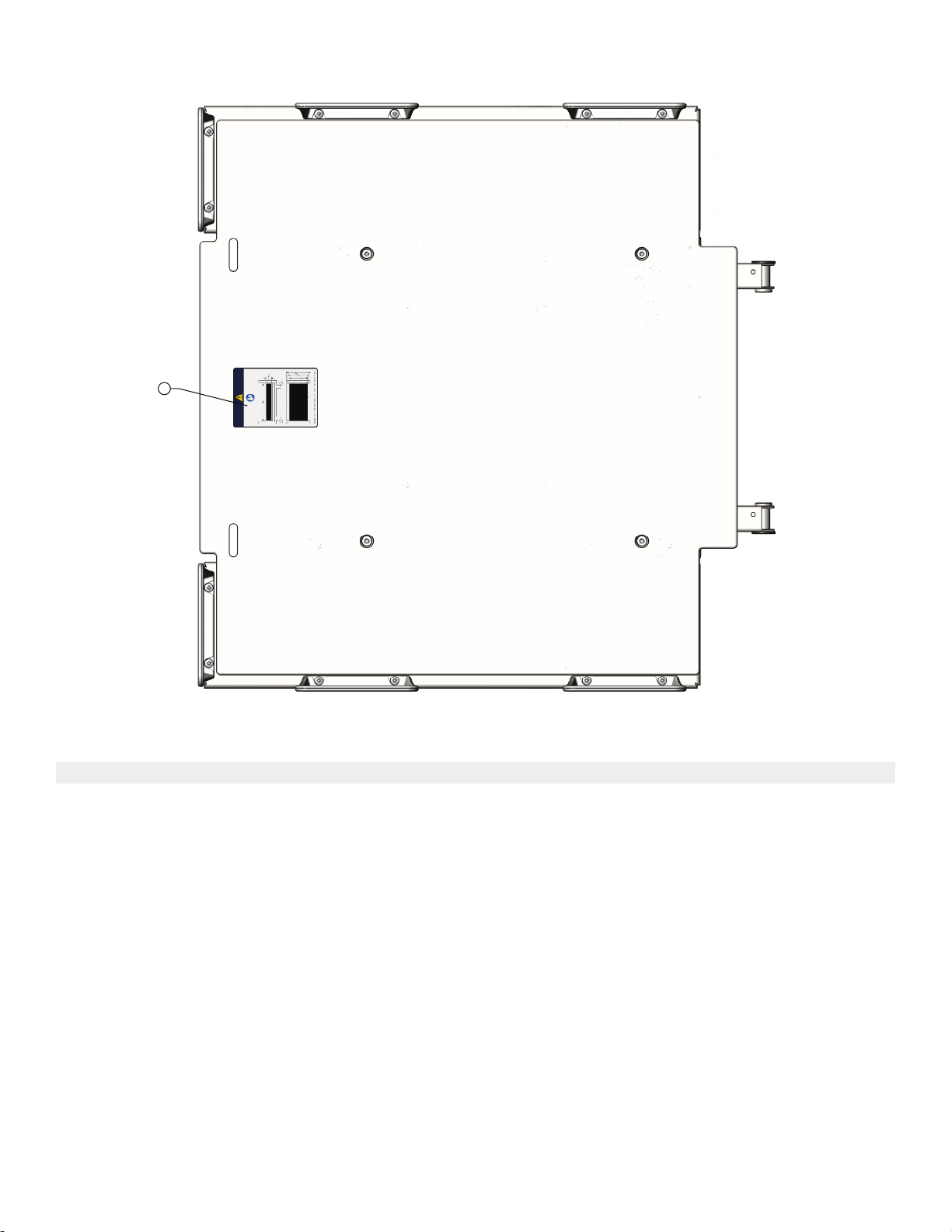
31
IItteemm NNuummbbeerr NNaammee QQuuaannttiittyy
1 5900240042 Deck weldment, head section 1
2 5900200068 Deck pan assembly, head deck, patient
1
right
3 5900200069 Deck pan assembly, head deck, patient
left
1
4 5900600007 Bushing, pinion shaft cover 2
5 5900500072 Pinion shaft, head deck 1
6 5900560003 Pinion gear, expandable deck 4
7 5900200051 Lock assembly, head deck position 1
8 5900520103P Cover pan, head deck electrical top
1
plated
9 5900520104P Cover pan, head deck electrical bottom
1
plated
10 5900620007 Cover, head deck 1
11 5900370022 Grommet, push-in locking 5/8" hole 8
12 5900340105 Screw, plastite pan head torx #8-16 x
2
1.25"lg zinc
5900-009-002 Rev A.0 63 EN
Page 68

IItteemm NNuummbbeerr NNaammee QQuuaannttiittyy
13 5900340101 Screw, rd hd flg hex drive 1/4-unc x 3/8lg
1
zinc
14 5900310020 Nutsert, #10-unf thick sheet hex body -
4
zinc
15 5900340114 Screw, plastite pan head ph #10-14 x 1/
8
2" lg znpl
16 5900340017 Screw, pan ph #8-unc x 0.3125 4
17 5900340090 Screw, sems pan ph #10-32unf x 3/4lg
12
int wash zinc
18 5900600035 Mattress keeper, short 6
19 0025-120-000 Rivet, 1/4 x 0.600" lg blind alum 12
20 5900400051 PCBA, jctn hd/ft pl-in/pr-out 1
21 5900400052 PCBA, jctn hd/ft pl-out/pr-in 1
22 5900340097 Screw, sems pan ph #6-32x1-1/2lg int
4
wash zinc pl
23 5900200159 Handle assembly, deck expansion 2
24 5900200160 Handle assembly, CPR 2
25 5900320021 Washer, flat 1.375 x 0.75 x 0.125 acetal 2
26 5900340081 Screw, flat Torx head 5/16-18 x 3/4 tri
4
lobe zinc
27 5900330003 Bushing, flg 0.375x0.500x0.313lg (flg
4
0.625x0.062)
28 5900690076 Label, indicator deck width 2
29 5900430091 HRNS, jctn pwr-comm int 1
30 5900430092 HRNS, jctn nc-spkr int 1
31 5900180089 Label, mattress replacement 1
32 3000-300-113 Cable tie, nylon 8” LG 2
EN 64 5900-009-002 Rev A.0
Page 69

DDeecckk ppaann aasssseemmbbllyy,, hheeaadd ddeecckk,, ppaattiieenntt rriigghhtt
7
4X
8
4X
6
4X
5
4X
1
2X
4
4X
3
2X
2
6
4X
5900200068 Rev A (Reference only)
IItteemm NNuummbbeerr NNaammee QQuuaannttiittyy
1 5900560011 Rack, expandable deck 2
2 5900240043 Pan weldment, head deck, patient right 1
3 5900600006 Bearing, expandable deck guide 2
4 5900600034 Roller, expandable deck 4
5 5900500028 Pin, expandable deck roller 4
6 0025-079-000 Rivet, 3/16 domed sst 8
7 5900370022 Grommet, push-in locking 5/8” hole 4
8 5900310020 Nutsert, #10-UNF thick sheet hex body-
zinc
4
5900-009-002 Rev A.0 65 EN
Page 70

DDeecckk ppaann aasssseemmbbllyy,, hheeaadd ddeecckk,, ppaattiieenntt lleefftt
7
1X
6
4X
5
4X
1
2X
4
4X
3
2X
6
4X
2
8
4X
9
4X
5900200069 Rev A (Reference only)
IItteemm NNuummbbeerr NNaammee QQuuaannttiittyy
1 5900560011 Rack, expandable deck 2
2 5900240044 Pan weldment, head deck, patient left 1
3 5900600006 Bearing, expandable deck guide 2
4 5900600034 Roller, expandable deck 4
5 5900500028 Pin, expandable deck roller 4
6 0025-079-000 Rivet, 3/16 domed sst 8
7 5900690050 Decal, deck lock position sensor 1
8 5900370022 Grommet, push-in locking 5/8” hole 4
9 5900310020 Nutsert, #10-UNF thick sheet hex body-
zinc
4
EN 66 5900-009-002 Rev A.0
Page 71
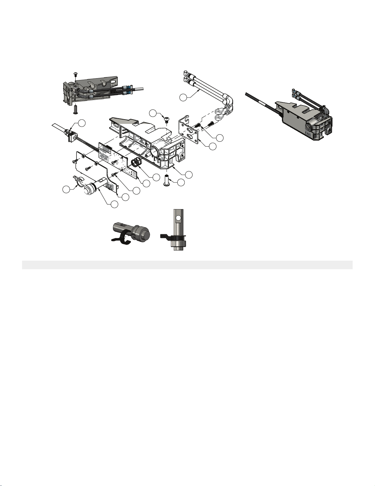
LLoocckk aasssseemmbbllyy,, hheeaadd ddeecckk ppoossiittiioonn
12
9
4X
4
10
1
11
8
2X
13
2X
6
7
3
2
5
5900200051 Rev A (Reference only)
IItteemm NNuummbbeerr NNaammee QQuuaannttiittyy
1 5900600048 Housing, deck lock/position sensor 1
2 5900600049 Cover, deck lock/sensor housing 1
3 5900500033 Pin, deck lock 1
4 5900370017 Spring, compression deck lock 1
5 5900520100 Plate, deck lock cable mount 1
6 5900430030 HRNS, deck lock/position snsr head
1
deck
7 5900600053 Arm, deck lock sensor plunger 1
8 5900340009 Screw, pan ph #6-unc x 0.375 tri lobe 2
9 5900340018 Screw, #4-20 tri-lobular 3/8lg 4
10 5900370018 Binding barrel, 10-24 x 3/4lg zinc plated 1
11 0004-665-000 Screw, bhcs #10-unc x 0.313 w/patch 1
12 590040004101 PCBA, iom deck pos mon head 1
13 5900370011 Cable, deck extend push/pull 2
5900-009-002 Rev A.0 67 EN
Page 72
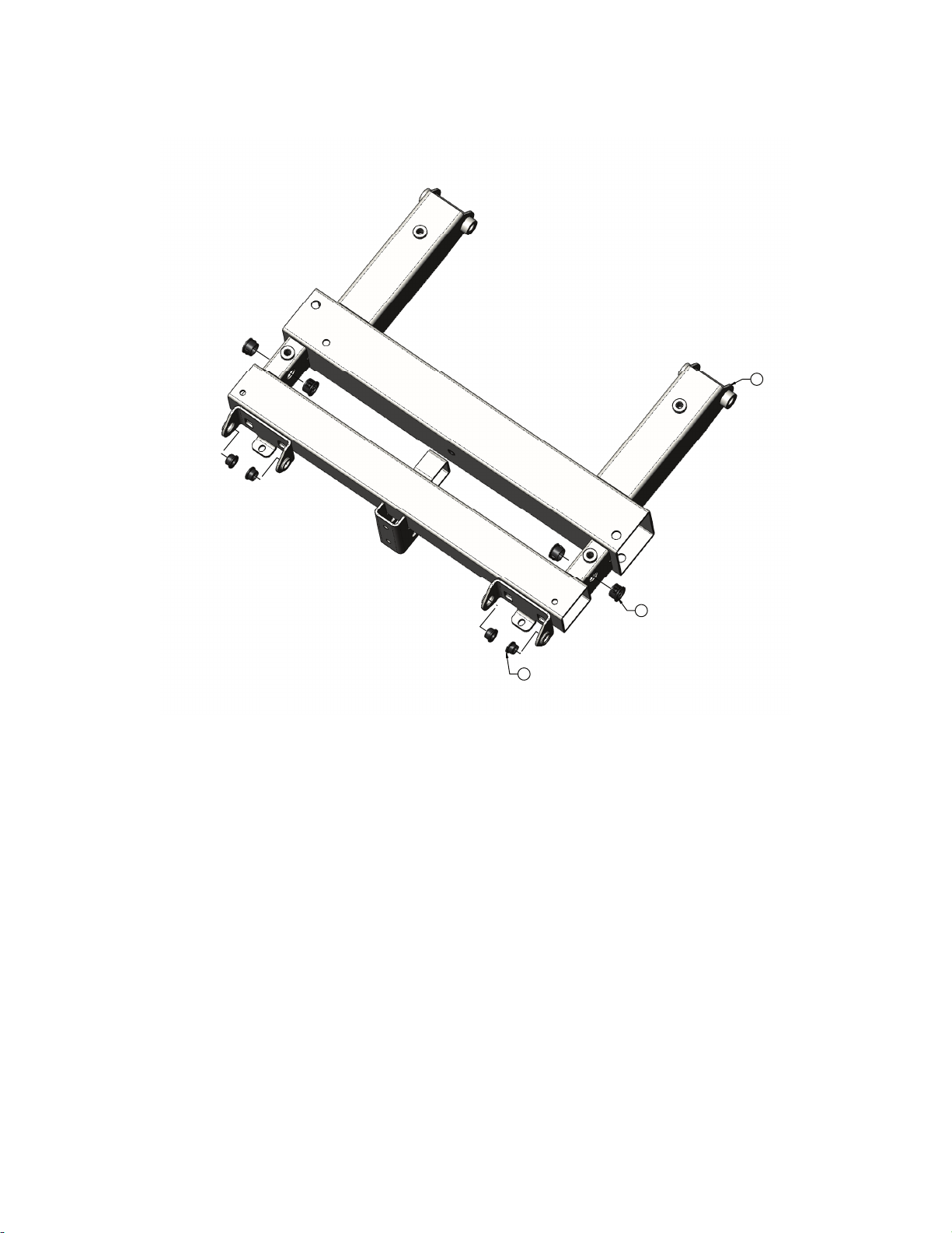
DDeecckk aasssseemmbbllyy,, kknneeee sseeccttiioonn
1
14
4X
9
4X
5900200056 Rev E (Reference only)
EN 68 5900-009-002 Rev A.0
Page 73

3
2
16
4X
16
5900-009-002 Rev A.0 69 EN
Page 74

15
2X
6
4
8
5
5
Torque item 15
to 25-30 in-lb
10
10
11
4X
13
13
12
4X
EN 70 5900-009-002 Rev A.0
Page 75
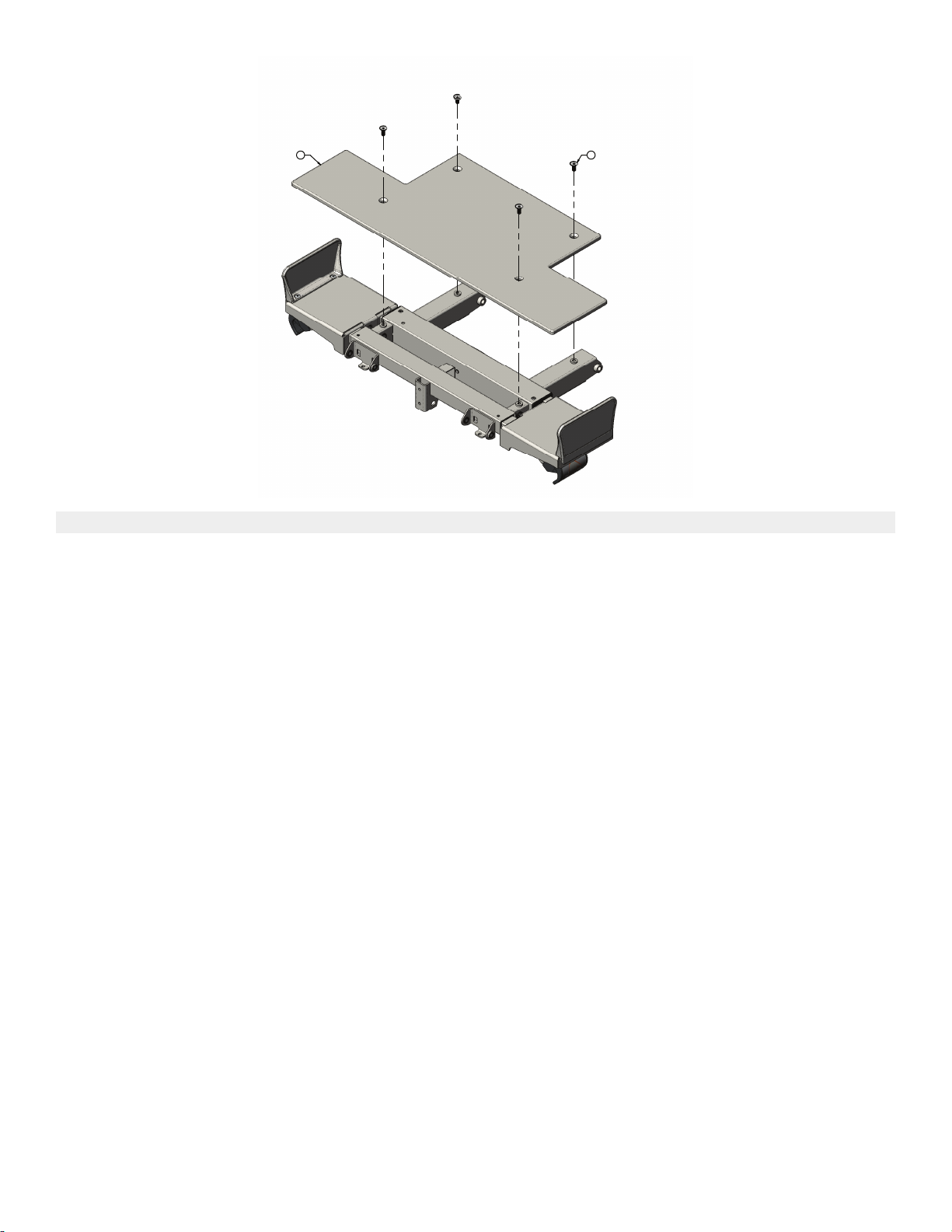
7 17
4X
IItteemm NNuummbbeerr NNaammee QQuuaannttiittyy
1 5900240045 Deck weldment, knee section 1
2 5900200072 Deck pan assembly, knee section,
1
patient left
3 5900200073 Deck pan assembly, knee deck, patient
1
right
4 5900500041 Pinion shaft, knee deck 1
5 5900560003 Pinion gear, expandable deck 2
6 5900600007 Bushing, pinion shaft cover 1
7 5900620008 Cover, knee deck 1
8 5900330007 Bushing, flg 0.313x0.375x0.125lg (flg
1
0.500x0.032)
9 5900330003 Bushing, flg 0.375x0.500x0.313lg (flg
4
0.625x0.062)
10 5900600035 Mattress keeper, short 2
11 0025-120-000 Rivet, 1/4 x 0.600" lg blind alum 4
12 5900340090 Screw, sems pan ph #10-32unf x 3/4lg
4
int wash zinc
13 5900200159 Handle assembly, deck expansion 2
14 5900370022 Grommet, push-in locking 5/8" hole 4
15 5900340017 Screw, pan ph #8-unc x 0.3125 2
16 5900340114 Screw, plastite pan head ph #10-14 x 1/
4
2" lg ZnPL
17 5900340081 Screw, flat Torx head 5/16-18 x 3/4 tri
4
lobe zinc
5900-009-002 Rev A.0 71 EN
Page 76

DDeecckk ppaann aasssseemmbbllyy,, kknneeee ddeecckk,, ppaattiieenntt rriigghhtt
3
5
2X
1
6
2X
7
4X
7
4X
4
2X
2
9
2X
8
2X
5900200073 Rev A (Reference only)
IItteemm NNuummbbeerr NNaammee QQuuaannttiittyy
1 5900560011 Rack, expandable deck 1
2 5900240047 Pan weldment, knee deck, patient right 1
3 5900600006 Bearing, expandable deck guide 1
4 5900600050 Bearing, slide knee deck 2
5 5900600034 Roller, expandable deck 2
6 5900500028 Pin, expandable deck roller 2
7 0025-079-000 Rivet, 3/16 domed sst 8
8 5900370022 Grommet, push-in locking 5/8” hole 2
9 5900310020 Nutsert, #10-UNF thick sheet hex body-
zinc
2
EN 72 5900-009-002 Rev A.0
Page 77

DDeecckk ppaann aasssseemmbbllyy,, kknneeee ddeecckk,, ppaattiieenntt lleefftt
6
2X
1
5
2X
3
7
2X
7
2X
7
4X
4
2X
2
9
2X
8
2X
5900200072 Rev A (Reference only)
IItteemm NNuummbbeerr NNaammee QQuuaannttiittyy
1 5900560011 Rack, expandable deck 1
2 5900240046 Pan weldment, knee deck, patient left 1
3 5900600006 Bearing, expandable deck guide 1
4 5900600050 Bearing, slide knee deck 2
5 5900600034 Roller, expandable deck 2
6 5900500028 Pin, expandable deck roller 2
7 0025-079-000 Rivet, 3/16 domed sst 8
8 5900370022 Grommet, push-in locking 5/8” hole 2
9 5900310020 Nutsert, #10-UNF thick sheet hex body-
zinc
2
5900-009-002 Rev A.0 73 EN
Page 78

DDeecckk aasssseemmbbllyy,, ffoooott sseeccttiioonn
14
17
14
14
14
17
1
2
3
15
15
15
15
15
15
15
15
15
5900200057 Rev G (Reference only)
EN 74 5900-009-002 Rev A.0
Page 79

16
16
6
5
5
4
16
16
6
5
5
Torque item 16
to 25-30 in-lb
Torque item 16
to 25-30 in-lb
12
12
13
7
5900-009-002 Rev A.0 75 EN
Page 80

10
9
9
19
19
21
22
20
21
22
18
EN 76 5900-009-002 Rev A.0
Page 81
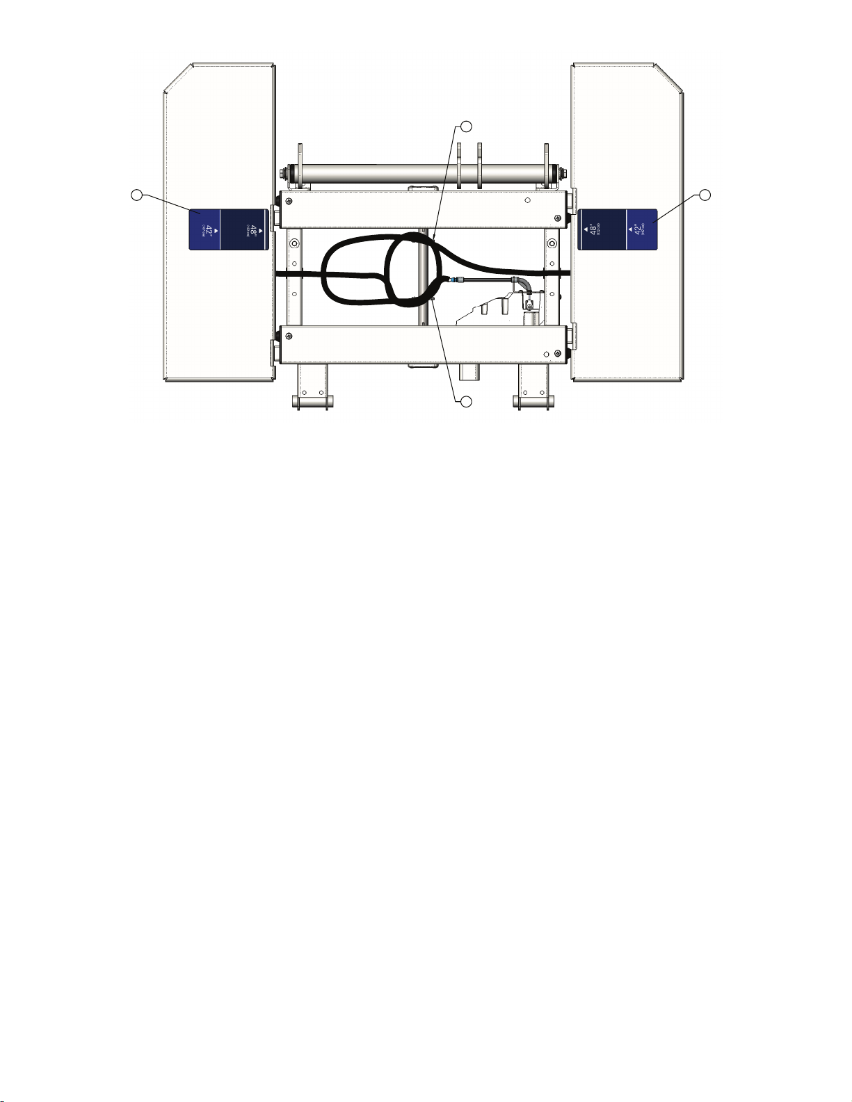
2323
27
27
5900-009-002 Rev A.0 77 EN
Page 82

11
11
8
EN 78 5900-009-002 Rev A.0
Page 83

26
26
26
24
25
IItteemm NNuummbbeerr NNaammee QQuuaannttiittyy
1 5900240106 Deck weldment, foot section 1
2 5900200074 Deck pan assembly, foot section, patient
left
3 5900200075 Deck pan assembly, foot section, patient
1
1
right
4 5900500040 Pinion shaft, foot deck 1
5 5900560003 Pinion gear, expandable deck 4
6 5900600007 Bushing, pinion shaft cover 2
7 5900200153 Lock assembly, foot deck position 1
8 5900620009 Cover, foot deck 1
9 5900340090 Screw, sems pan ph #10-32UNF x 3/
4
4LG int wash zinc
10 5900200159 Handle assembly, deck expansion 2
11 5900340081 Screw, flat Torx head 5/16-18 x 3/4 tri
2
lobe zinc
12 5900340105 Screw, plastite pan head Torx #8-16 x
2
1.25”LG zinc
13 5900340101 Screw, rd hd flg hex drive 1/4-UNC x 3/
8LG zinc
1
14 5900370022 Grommet, push-in locking 5/8” hole 4
15 5900340114 Screw, plastite pan head PH #10-14 x 1/
2” LG ZnPL
8
16 5900340017 Screw, pan ph #8-UNC x 0.3125 4
5900-009-002 Rev A.0 79 EN
Page 84

IItteemm NNuummbbeerr NNaammee QQuuaannttiittyy
17 5900330020 Bushing, flg 0.500X0.625X0.313LG (flg
2
0.875X0.062)
18 5900240107 Gatch weldment, foot bail 1
19 5900620026 Bushing, timing link 2
20 5900500167 Pivot rod, foot bail 1
21 0011-003-000 Washer, plain 5/16 x 0.688 ap 2
22 8839-793-700 Screw, hxcap 5/16-UNC x 0.75 2
23 5900690076 Label, indicator deck width 2
24 5900600036 Mattress keeper, long 1
25 5900540279P Backing plate, foot end mattress keeper
1
plated
26 0025-120-000 Rivet, 1/4 x 0.600” lg blind alum 3
27 3000-300-113 Cable tie, nylon 8” lg 2
EN 80 5900-009-002 Rev A.0
Page 85

DDeecckk ppaann aasssseemmbbllyy,, ffoooott ddeecckk,, ppaattiieenntt rriigghhtt
5
4X
3
2X
4
4X
1
2X
6
4X
6
4X
7
2
9
2X
8
2X
5900200075 Rev A (Reference only)
IItteemm NNuummbbeerr NNaammee QQuuaannttiittyy
1 5900560011 Rack, expandable deck 2
2 5900240051 Pan weldment, foot deck, patient right 1
3 5900600006 Bearing, expandable deck guide 2
4 5900600034 Roller, expandable deck 4
5 5900500028 Pin, expandable deck roller 4
6 0025-079-000 Rivet, 3/16 domed sst 8
7 5900690050 Decal, deck lock position sensor 1
8 5900370022 Grommet, push-in locking 5/8” hole 2
9 5900310020 Nutsert, #10-UNF thick sheet hex body-
zinc
2
5900-009-002 Rev A.0 81 EN
Page 86

DDeecckk ppaann aasssseemmbbllyy,, ffoooott ddeecckk,, ppaattiieenntt lleefftt
2
3
2X
4
4X
1
2X
6
4X
5
4X
6
4X
8
2X
7
2X
5900200074 Rev A (Reference only)
IItteemm NNuummbbeerr NNaammee QQuuaannttiittyy
1 5900560011 Rack, expandable deck 2
2 5900240050 Pan weldment, foot deck, patient left 1
3 5900600006 Bearing, expandable deck guide 2
4 5900600034 Roller, expandable deck 4
5 5900500028 Pin, expandable deck roller 4
6 0025-079-000 Rivet, 3/16 domed sst 8
7 5900370022 Grommet, push-in locking 5/8” hole 2
8 5900310020 Nutsert, #10-UNF thick sheet hex body-
zinc
2
EN 82 5900-009-002 Rev A.0
Page 87
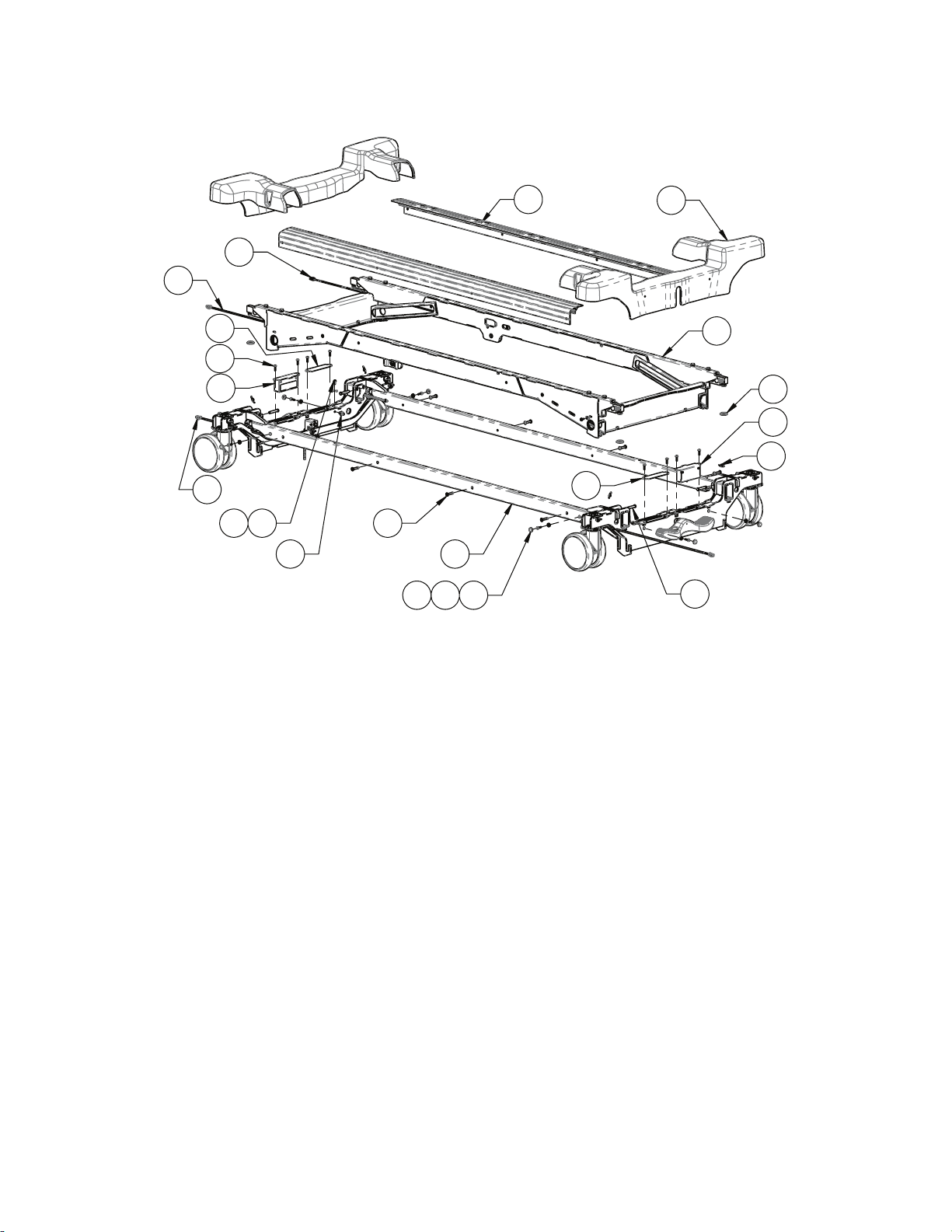
HHIILLOO ffrraammee aasssseemmbbllyy
1
2
8
4
3
576
15
9
10
7
11
17
16
18
12
13
15
20
19
21
5900200122 Rev D (Reference only)
5900-009-002 Rev A.0 83 EN
Page 88
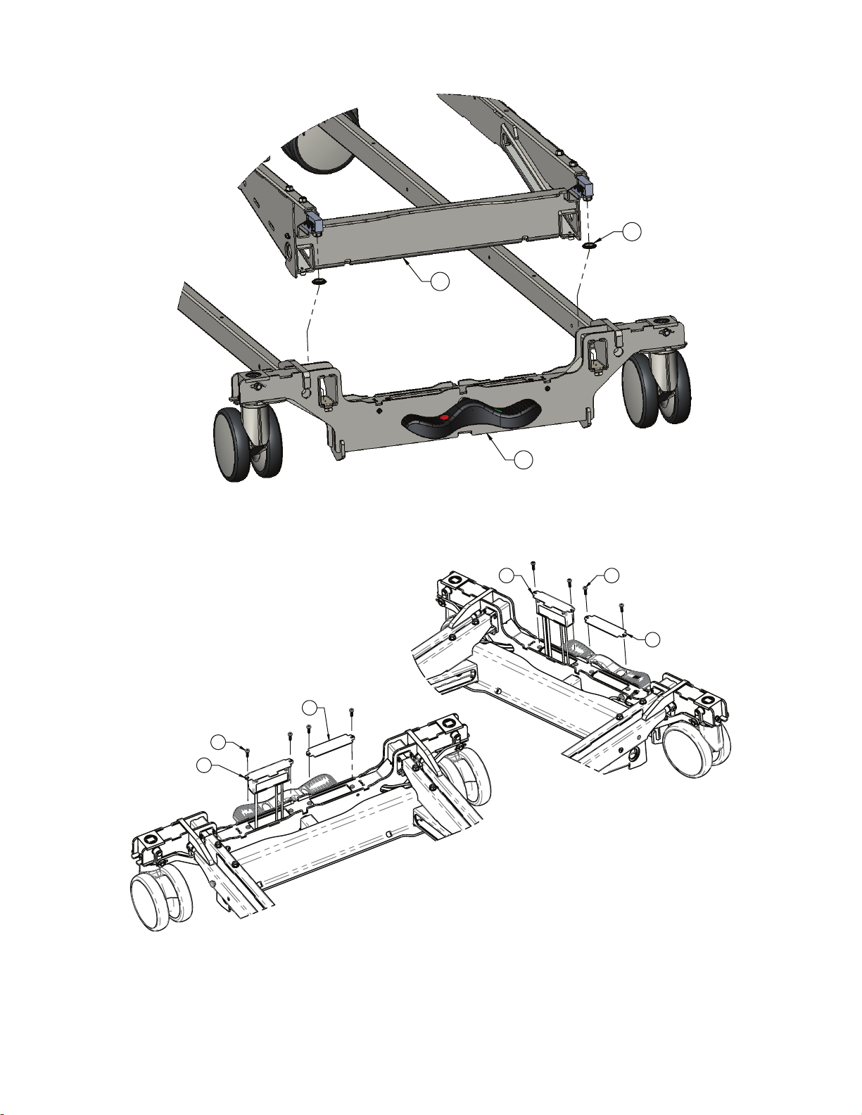
2
1
21
4X
7
4X
13
15
7
4X
15
12
EN 84 5900-009-002 Rev A.0
Page 89

A
DETAIL A
11
20
19
Torque item 11
to 50-70 in-lb
11
20
Torque item 11
to 50-70 in-lb
IItteemm NNuummbbeerr NNaammee QQuuaannttiittyy
1 5900200124 Caster frame assembly 1
2 5900200123 Lower frame assembly 1
3 5900370089 Rivet, 1/4 x 1” domed zinc plated steel 8
4 5900580005 Extrusion, lower frame side rail 2
5900-009-002 Rev A.0 85 EN
Page 90

IItteemm NNuummbbeerr NNaammee QQuuaannttiittyy
5 5900350017 Snap-cap cover #12/12 white 8
6 5900350003 Snap-cap washer #12/12 flat bottom 8
7 5900340090 Screw, sems pan ph #10-32UNF x 3/
16
4LG int wash zinc
8 5900640006 Caster cover 2
9 5900350033 Clevis pin Ø5/16” x 1-3/4” (1-1/2” UL)
4
zinc
10 0027-019-000 Rue ring, 5/16” 4
11 5900340079 Screw, #10-32 x 1/2LG hex washer head
3
elec ground
12 5900280039 Electrical assembly, IOM scale-head 1
13 5900280040 Electrical assembly, IOM scale-foot 1
15 5900520201P Plate, caster bracket access cover-
2
plated
16 5900430133 HRNS, scale interconnect 1
17 5900430161 HRNS, brake-steer detect (lower) 1
18 5900430162 HRNS, scale pwr-comm (lower) 1
19 5900350041 Cable tie, fir tree mount 1mm-35mm
1
bundle blk
20 5900520247 Clip, ground strap anti rotate ring 3
21 5900500174 Load cell mount shoe 4
EN 86 5900-009-002 Rev A.0
Page 91
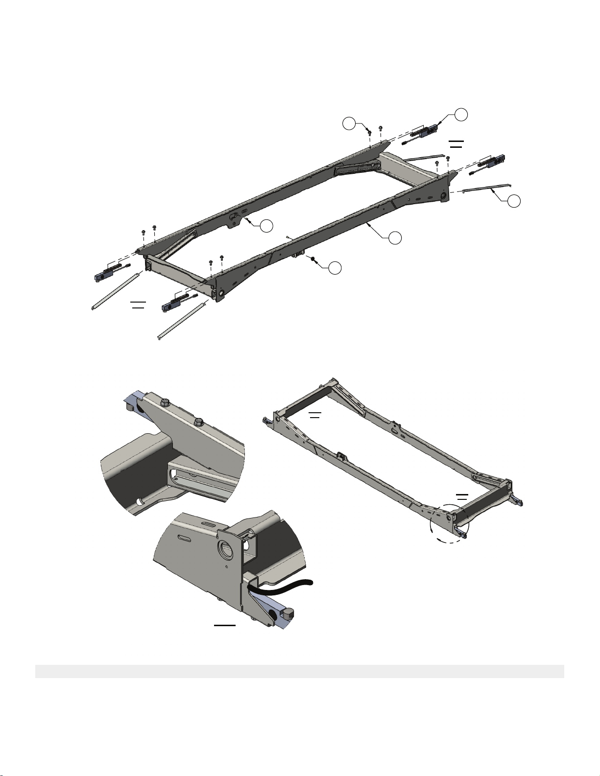
LLoowweerr ffrraammee aasssseemmbbllyy
HEAD
END
FOOT
END
2
8X
3
4X
6
4X
4
2X
5
2X
1
Torque item 2
to 150-180 in-lb
B
HEAD
END
FOOT
END
DETAIL B
5900200123 Rev B (Reference only)
IItteemm NNuummbbeerr NNaammee QQuuaannttiittyy
1 5900240100 Weldment, lower inner frame 1
2 5900340092 Screw, serrated hex flg 5/16-UNC x
8
0.75LG zinc
5900-009-002 Rev A.0 87 EN
Page 92

IItteemm NNuummbbeerr NNaammee QQuuaannttiittyy
3 5900280027 Sensor assembly, load cell K-SBS 4
4 5900330020 Bushing, flg 0.500X0.625X0.313LG
2
(FLG 0.875X0.062)
5 5900310020 Nutsert, #10-UNF thick sheet hex body-
2
zinc
6 5900520226 Wear strip, HILO lift slide 4
EN 88 5900-009-002 Rev A.0
Page 93
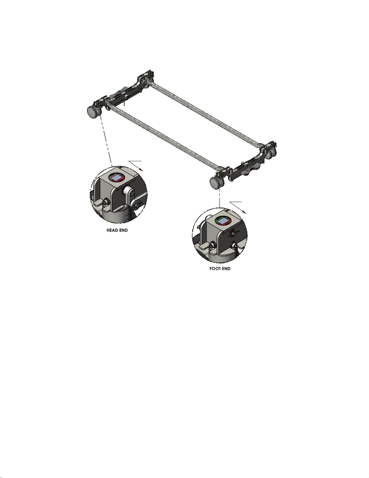
CCaasstteerr ffrraammee aasssseemmbbllyy
GREEN/RED CASTER
STEM ORIENTATION
RED SIDE TOWARDS
FOOT END OF BED
GREY/RED CASTER
STEM ORIENTATION
RED SIDE TOWARDS
FOOT END OF BED
5900200124 Rev D (Reference only)
5900-009-002 Rev A.0 89 EN
Page 94
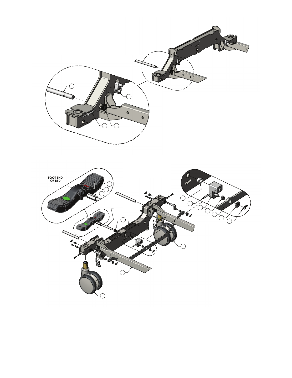
10
24 18
7
3
21
1
3
APPLY NS-18191-G
GREASE TO SHAFT
(TYPICAL BOTH ENDS)
13
4
6
20
13
17
22
8
CENTER BRAKE CHANGE LEVER DETAIL
( TYPICAL BOTH HEAD AND FOOT)
21
11
EN 90 5900-009-002 Rev A.0
Page 95

19
14
16
9
20
17
22
20
22
CASTER CHANGE LEVER DETAILS
( TYPICAL 4 CORNERS)
11
16
14
TORQUE TO
140-160in/lbs TYP
TORQUE TO
140-160in/lbs TYP
29
29
5
2
2
23
12
15
GROUND STRAP INSTALLED ON PATIENT LEFT
HEAD & PATIENT RIGHT FOOT INNER FRAME RAILS.
ORIENT GROUND STRAP AS SHOWN
USING ANTI-ROTATE CLIP.
26
25
28
STATIC CHAIN INSTALLED
ON BOTTOM OF HEAD
END CASTER BRACKET
(BRAKE SWITCH END)
27
25
TORQUE TO
50-70in/lbs
BRAKE SWITCH INSTALLED
ON HEAD END ONLY
TORQUE TO
50-70in/lbs TYP
5900-009-002 Rev A.0 91 EN
Page 96

IItteemm NNuummbbeerr NNaammee QQuuaannttiittyy
1 5900200118 Frame weldment, caster frame with
1
inserts
2 5900360004 Caster, 558X twin wheel, head, Ø6”,
2
white
3 5900360005 Caster, 559X twin wheel, foot, Ø6”, white 2
4 5900500168P Shaft, composite brake pedal head
2
plated
5 5900200045 Brake pedal-composite assembly w/
1
labels-head
6 5900200161 Brake pedal-composite assembly w/
1
labels-foot
7 5900560024 Lever, brake rod linkage 4
8 5900560025 Foot pedal change lever 2
9 5900560026 Lever, caster change 4
10 5900500124 Brake transfer rod, 5/8” 2
11 5900540229 Linkage, brake connecting 2
12 5900520180P Bracket, brake switch 1
13 0026-012-000 Pin, spring 3/16” x 1.25”LG blk ox 4
14 5900320030 Washer, lock reg M6 8
15 5900340090 Screw, sems pan ph #10-32UNF x 3/
2
4LG int wash zinc
16 5900340093 Screw, SHCS M6x1 x 18mm lg zinc 8
17 5900320027 Washer, flat 3/8 x 7/8 x 0.063 nylon 6
18 5900330014 Bushing, FLG 0.625x0.750x0.375LG
4
(FLG 1.000x0.062)
19 5900330020 Bushing, FLG 0.500x0.625x0.313LG
4
(FLG 0.875x0.062)
20 5900330003 Bushing, FLG 0.375x0.500x0.313LG
14
(FLG 0.625x0.062)
21 5900330022 Bushing, FLG 0.510x0.633x0.500LG
4
(FLG 0.875x0.125)
22 0027-022-000 Rue ring, 3/8” 10
23 5900410030 Switch, SPDT-N/O-N/C omron D3D-211 1
24 5900370089 Rivet, 1/4 x 1” domed zinc plated steel 4
25 5900340079 Screw, #10-32 x 1/2LG hex washer head
3
elec ground
26 5900430150 HRNS, GND braid E 2
27 3001-200-052 Chain, sash #8 zinc steel-static ground 1
28 5900520247 Clip, ground strap anti rotate ring 2
29 5900320028 Washer, plain #12 x 0.562 AP 8
EN 92 5900-009-002 Rev A.0
Page 97
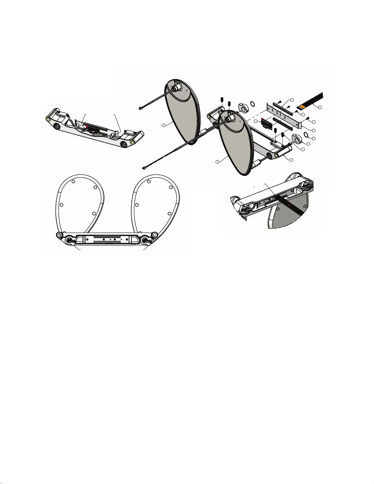
RRaaiill aasssseemmbbllyy,, hheeaadd
2
3
1
20
2X
31
2X
38
4X
22
2
X
53
49
2X
52
2X
50
51
CA
M LOBE ORIENTATION (IDENTIFICATION MARKS FACE OUTWARD)
FLEX CABLE TO BE INSTALLED WITH
RED LABEL INDICATOR FLUSH WITH
END OF CASTING. ( 1/4")
ROUTE ARM CABLES UNDER
POSTS & CONNECT TO PCBA
CASTING CUT-AWAY
FOR CLARITY
5900200130 Rev C (right) (Reference only)
5900200131 Rev C (left) (Reference only)
5900-009-002 Rev A.0 93 EN
Page 98
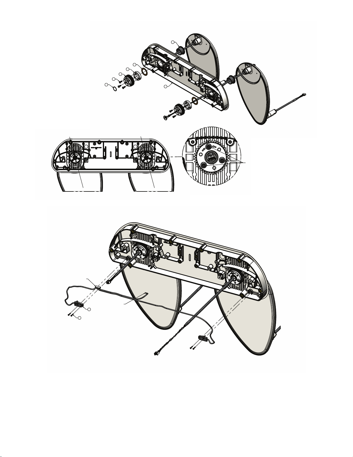
21
2X
23
2X
5
2X
6
2X
32
6X
30
2X
4
CENTERLIN
E
OF
ARM
C
ENTERLINE OF ARM
INSTALL GEARS WITH ARROWS POINTING TO TOP SCREW
RELATIVE TO ARM CENTERLINE. TYPICAL BOTH ARMS.
START SCREWS IN THREADS - DO NOT TIGHTEN AT THIS TIME.
40
2X
24
4X
CONNECT RAIL POSITION HARNESS TO CORRESPONDING
SWITCHES, ORIENT AND INSTALL AS SHOWN.
CONNECT LOCK HARNESS
CONNECTOR DURING LATCH
ASSEMBLY INSTALLATION.
CONNECT TO 6-PIN
HEADER ON PCBA
EN 94 5900-009-002 Rev A.0
Page 99

192X28
2X
18
2X
10
16
29
17
7
APPLY NS-18191-G
GREASE TO LENGTH
OF RACK
APPLY NS-18191-G
GREASE TO LENGTH
OF RACK
TIGHTEN RACK MESH SET SCREW TO ENSURE GEAR
MESH IS TIGHT. FUNCTIONALLY CYCLE TEST TO ENSURE
CORRECT SETTING FOR GRAVITY FALL AND "HITCH"
ADJUST BOTH LEVER SET SCREWS AT THE SAME TIME.
RACK MESH
ADJUSTING
SET SCREW
AFTER MESH IS TIGHT, TORQUE ALL GEAR
SCREWS TO 45IN/LB (TWICE AROUND)
12
9
8
36
27
2X
26
2X
35
2X
11
26
2X
37
22
16X
8.00 0.5
0.25
PLACE TAPE APPROXIMATELY AS SHOWN ON BACKPLATE
1137
5900-009-002 Rev A.0 95 EN
Page 100
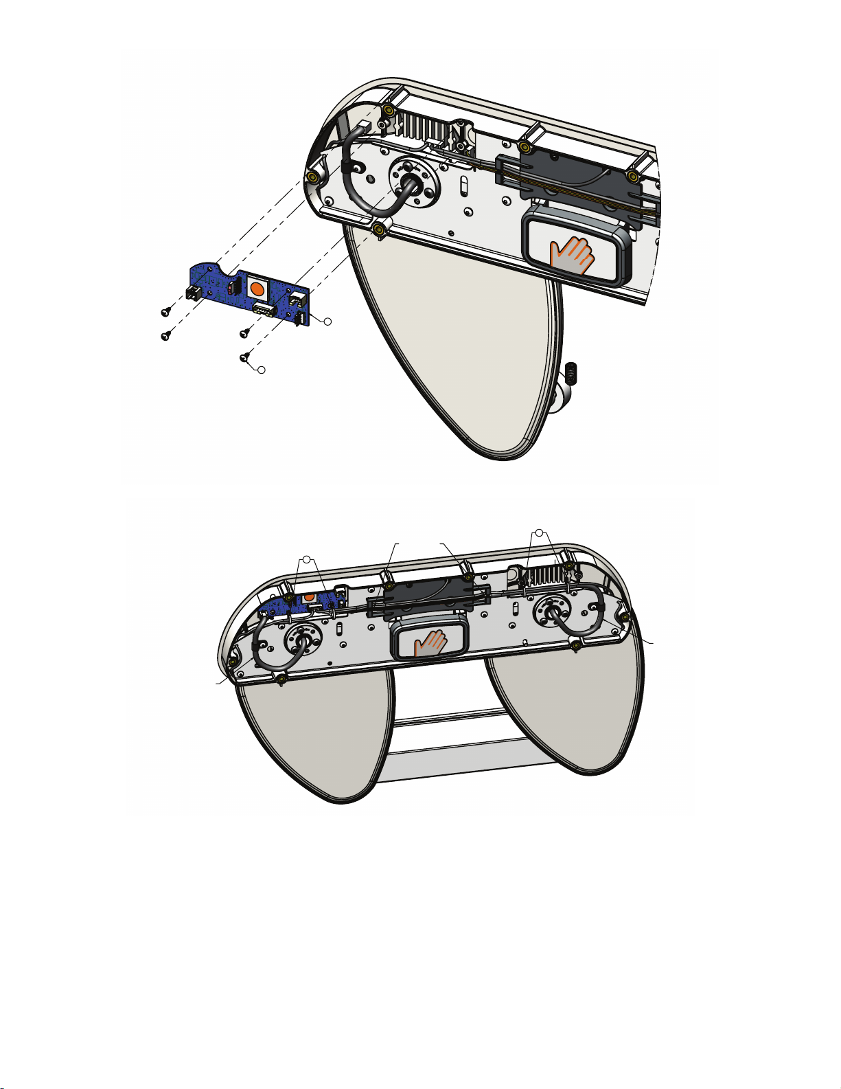
25
4X
39
WIRE HARNESS ROUTING
ROUTE ALL HARNESSES AS SHOWN.
ROUTE HARNESSES UNDER
PLATE TABS AS SHOWN.
LOOP RAIL ARM HARNESS AS SHOWN,
ORIENT P-CLIP HORIZONTALLY.
CONNECT TO PCBA.
LOOP RAIL ARM HARNESS AS SHOWN,
ORIENT P-CLIP HORIZONTALLY.
CONNECT TO PCBA.
57
57
CABLE TIE WIRES NEATLY
TO BACKPLATE
CABLE TIE WIRES NEATLY
TO BACKPLATE
EN 96 5900-009-002 Rev A.0
 Loading...