

Page 1

User Manual
Mistral-Air® Warming Unit - SYK
MA1100-PM (110-120V~, 60 Hz)
Distributed by:
Page 2

INT/R295-EN-PM/4-09/14
2
Page 3

INT/R295-EN-PM/4-09/14
3
Foreword ...................................................................................................... 4
Disclaimer .................................................................................................... 4
1 Contra-indications, Safety Precautions, Symbols and Graphics .... 5
1.1 Contra-indications ....................................................................... 5
1.2 Safety Precautions...................................................................... 5
1.3 Symbols ...................................................................................... 8
1.4 Mistral- Air® Graphics ............................................................... 11
2 Indications For Use ............................................................................ 12
3 Temperature Management ................................................................ 12
4 Forced Air Warming ........................................................................... 12
5 Description of Mistral-Air® Plus Warming Unit ............................... 12
5.1 The Appliance ........................................................................... 13
5.2 The Control Panel ..................................................................... 13
6 Preparing the Mistral-Air® Plus Warming Unit For Use .................. 14
7 Mounting the Mistral-Air® Plus Warming Unit ................................. 14
8 User Instructions ................................................................................ 15
8.1 Connection to Power Supply .................................................... 15
8.2 Switching the Unit On ............................................................... 16
8.3 Connecting the Blanket ............................................................ 16
8.4 Warming Up With the Mistral-Air Plus Warming Unit ............. 17
8.4.1 Temperature settings......................................................... 17
8.4.2 Temperature Selection ...................................................... 17
8.5 Stop Warming ........................................................................... 18
9 Safety Systems and Alarms .............................................................. 18
9.1 General Alarms ......................................................................... 18
9.2 Other Safety Features .............................................................. 19
9.3 The Blankets ............................................................................. 20
10 Maintenance ........................................................................................ 21
11 Storage and Cleaning ........................................................................ 21
12 Replacing the Filter ............................................................................ 22
13 Reset the Hour Meter ......................................................................... 24
14 Replacing the Hose ............................................................................ 25
15 Replacing the Power Cord ................................................................ 25
16 Parts Replacement ............................................................................. 26
17 Spare Parts and Order List ................................................................ 26
18 Specifications ..................................................................................... 27
19 Electromagnetic Compatibility ......................................................... 28
19.1 Electromagnetic immunity ........................................................... 28
19.2 Electromagnetic Emissions ................................................... 31
19.3 Recommended Separations Distances................................. 32
20 Warranty .............................................................................................. 33
Page 4

INT/R295-EN-PM/4-09/14
4
Foreword
Congratulations on your purchase of the Mistral-Air® Plus Forced Air
Warming Unit.
This device was developed with and for users and is built in accordance to
the latest safety standards.
We wish you every success in preventing and controlling hypothermia and
we are sure that the Mistral-Air Plus warming unit can help you to do so.
Please read this manual carefully before using the Mistral-Air® Plus warming
unit.
The 37Company
Disclaimer
The 37Company reserves all rights. No part of this document may be
reproduced or published, electronically, mechanically, in print, photographic
print, on microfilm or by any other means whatsoever, without the explicit
consent of The 37Company.
The content of this document has been compiled with the greatest possible
care and this information can be regarded as reliable. Nevertheless,
The 37Company is not liable for any consequences arising from the use of
the manual.
The 37Company reserves the right to make alterations and improvements to
the device.
The 37Company cannot be held liable for the final outcome of the patients’
treatment.
This document contains proprietary information that may not be disclosed to
third parties. This document may not be used without the explicit written
consent of The 37Company.
These instructions are intended for personnel authorised to work with and/or
service the medical device mentioned in this manual.
Contact Stryker Medical for detailed technical information for this device.
Page 5
INT/R295-EN-PM/4-09/14
5
1 Contra-indications, Safety Precautions, Symbols
and Graphics
Your Mistral-Air® Plus warming unit was designed and built with safety in
mind. The unit should provide reliable service and high quality patient care.
However, there is no replacement for care providers being attentive to their
patients’ needs and equipment operation. Read and understand all warnings
and precautions before using or prescribing the Mistral-Air® Plus warming
unit.
1.1 Contra-indications
Do not apply heat directly to open wounds.
Do not apply the warming system to ischemic limbs.
a. Use caution and consider discontinuing use on patients during
vascular surgery when an artery is clamped to an extremity (i.e.
aortic cross-clamping)
b. Use caution and monitor closely if used on patients with severe
peripheral vascular disease
1.2 Safety Precautions
Adequate grounding reliability can only be achieved when the
equipment is connected to an equivalent receptacle marked ‘hospital
grade’.
Prevent the blanket material from coming into direct contact with a
laser or an electrosurgical active electrode, rapid combustion could
result.
Using power cords or spare parts for internal components other than
specified by The 37Company may result in increased emission or
decreased immunity of the Mistral-Air® Plus warming unit.
When replacing the hose, do not touch the temperature sensors. If
these sensors are touched in any way, the unit must be recalibrated.
Portable and mobile RF (Radio Frequency) communication
equipment, and HF (High Frequency) surgical instruments or
endocardial catheters can affect the correct functioning of the
Mistral-Air® Plus warming unit.
The Mistral-Air® Plus warming unit is fitted with an air filter; however
airborne contamination shall be taken into consideration when using
the warming system.
Page 6
INT/R295-EN-PM/4-09/14
6
In order to prevent the patient from becoming hypothermic due to
unanticipated loss of power, connect the unit to the emergency
mains power.
When the unit is switched off, use of good thermal conductivity
materials on the patient could decrease the patient temperature.
The heating device does not contain an alarm system with an
interruption of power supply/supply mains alarm condition. This
means that in case of a power failure, there will be no alarm.
The unit is not equipped with an isolating switch. Temporary
interruption of the supply mains will render the device in Stand-by
Mode.
The Mistral-Air® Plus warming unit is certified according to IEC
60601-1-2 for electromagnetic interference. However, if
electromagnetic interference with nearby devices is experienced, the
user is encouraged to correct the interference by one or more of the
following measures:
•Isolate the offending device.
•Reorient or relocate the Mistral-Air® Plus warming unit.
•Increase the distance between the interfering device and the
Mistral-Air® Plus warming unit.
Use another electrical outlet.
•If assistance is required, please contact your local dealer.
•The Mistral-Air® plus warming unit shall not be used adjacent to or
stacked with other equipment.
Do not use the Mistral-Air® Plus warming unit with any forced air
disposables other than Mistral-Air® blankets. Thermal injury may
result.
Do not place the unit in or on the bed with the patient.
Monitor patient skin routinely.
Monitor patient temperature routinely.
A physician order is required for setting temperature and for
continued use.
Page 7
INT/R295-EN-PM/4-09/14
7
Neonates and pediatric patients of low weight will have a tendency to
overheat more readily than adults. Failure to monitor core
temperature could result in abnormal elevation of body temperature
resulting in serious injury or death.
If patient temperature is not responding or does not reach prescribed
temperature in prescribed time notify physician.
Place the unit in such way that the mains plug could be disconnected
easily in case of emergency.
Warming transdermal medications (patches) can increase drug
delivery, resulting in possible harm to the patient
To remove all power from the Mistral-Air® Plus warming unit, the
mains power cord must be removed from the electrical receptacle.
Stay in viewpoint of the user interface when performing the self-test,
and selecting the set-point.
In case of temperature alarm, check for free airflow. Ensure blanket
is not folded and do not place tools/equipment on the blanket which
could result in a blocked air flow. Be sure the air inlet is free. If the
unit continues to alarm, take the unit out of use and contact the
hospital service department or the local supplier.
Mistral-Air® blankets need to be used with the soft blue material
towards the patient’s skin and the white or reflective layer away from
the patient’s skin. The blue side provides the air distribution towards
the patient.
Never fold the blankets during use.
Do not obstruct blanket channels by e.g. instruments/tape/clamps.
Do not return the unit from service without the filter present.
Page 8
INT/R295-EN-PM/4-09/14
8
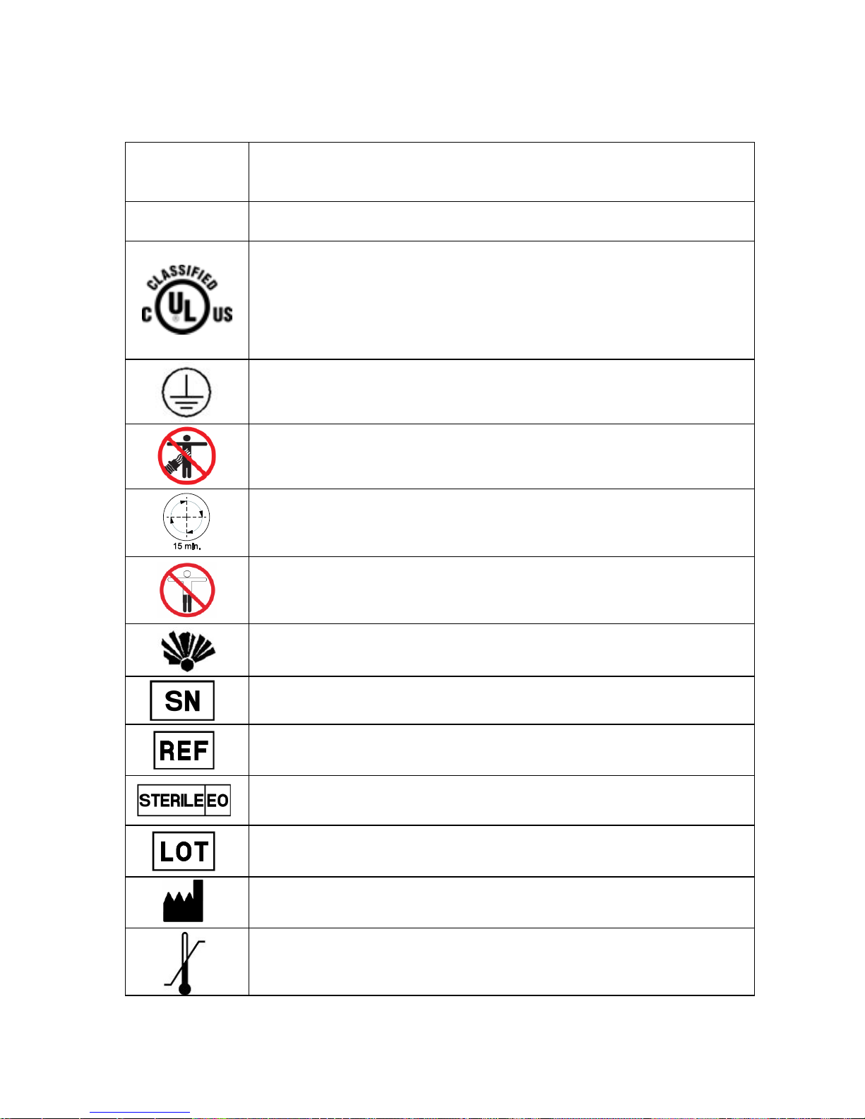
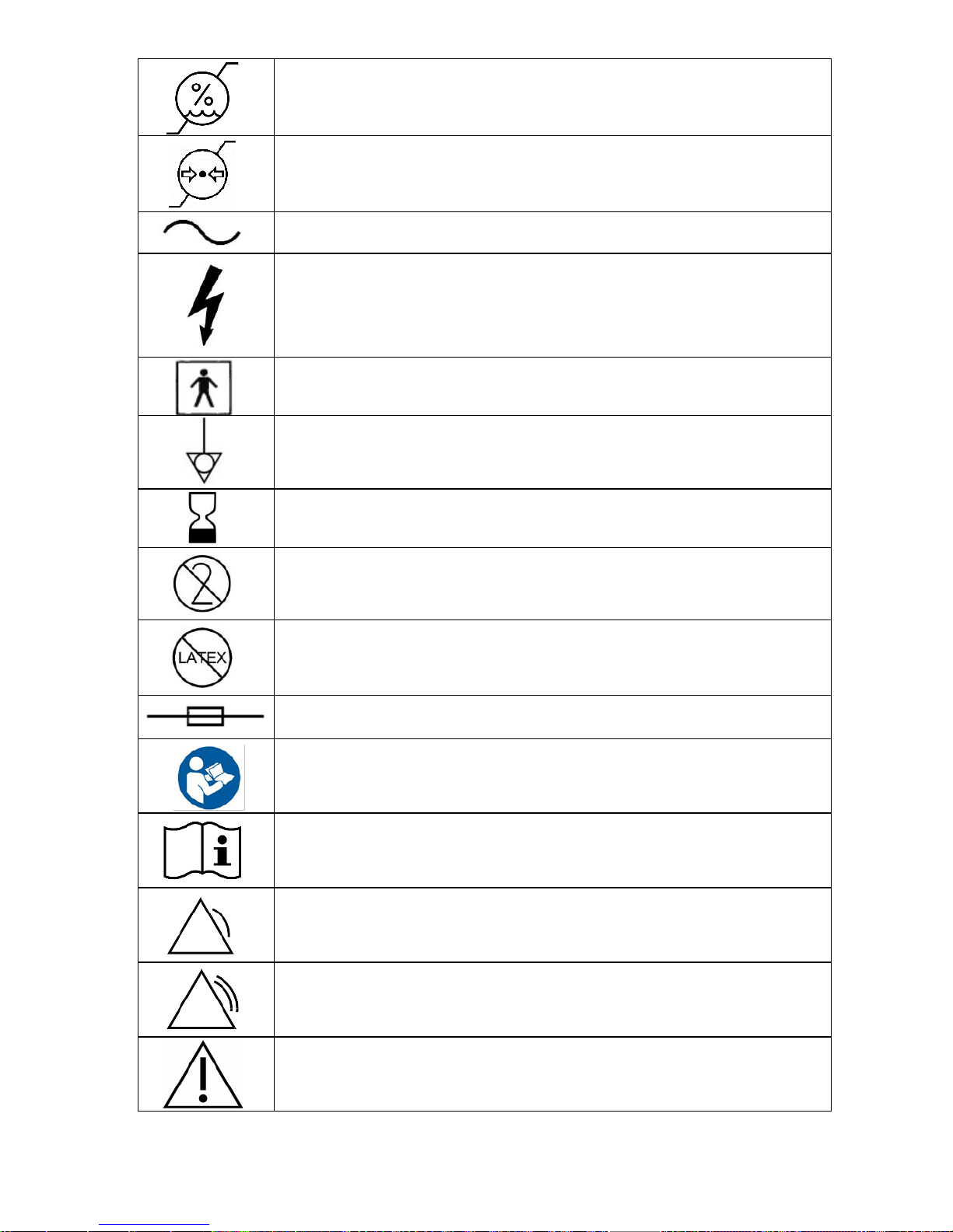
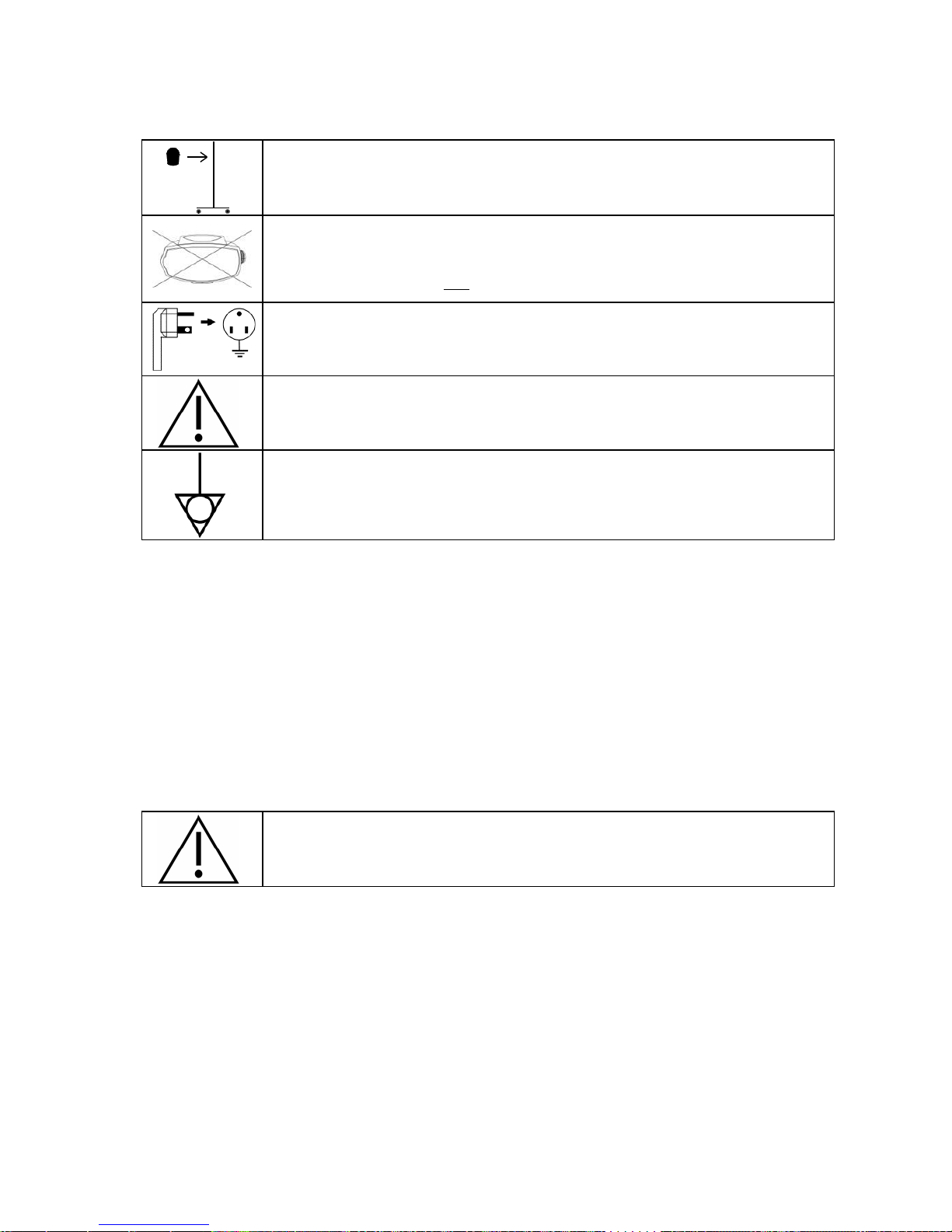
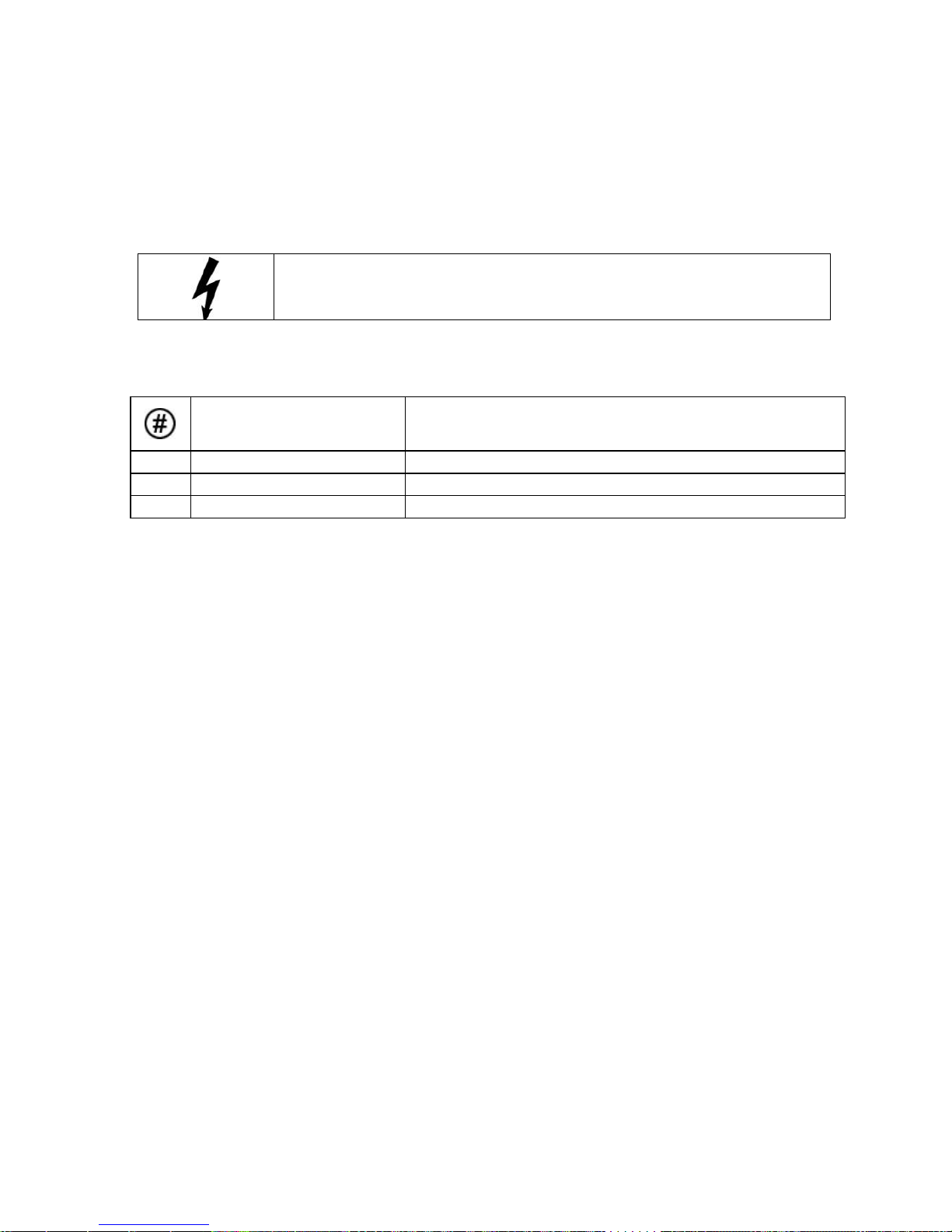
1.3 Symbols
This paragraph contains a list of official symbols.
IP21
Protected against solid foreign objects of 12 mm Ø and greater.
Protected against vertically falling water drops (according to IEC
60529).
Rx only
Caution: Federal US law restricts this device to sale by or on
order of a physician.
With respect to electric shock, fire and mechanical hazards only.
In accordance with IEC 60601-1, UL 60601-1, CAN/CSA C22.2
No. 601.1 and ASTM F2196-02 45YV.
Connect the Mistral-Air® Plus warming unit to an earthed socket
only. Risk of electrical shock exists if the equipment is not
connected to a properly grounded receptacle.
No free hosing. CAUTION! Hose nozzle MUST be connected to a
compatible forced air blanket or thermal injury may occur
Check patient’s temperature and skin condition at least every 15
minutes.
Do not apply to patients with ischemic limbs.
Do not use Mistral-Air® Plus warming unit and blankets near
flammable anaesthetics, to avoid the risk of explosion.
Serial number
Catalogue / article number
Sterile, method of sterilisation ethylene oxide
Batch code / lot number
Manufacturer
Transport and storage ambient temperature range
Page 9
INT/R295-EN-PM/4-09/14
9
Transport and storage relative humidity range
Transport and storage atmospheric pressure range
AC voltage
Electrical shock hazard. Do not disassemble the Mistral-Air® Plus
Warming Unit unless you are a qualified service technician. There
are electrically live parts within the unit when it is connected to a
power supply.
Type BF applied parts (according to IEC 60601-1)
Equipotentiality
Expiry date, year/month
For single patient use only. Do not re-use.
Does not contain natural latex components
Transformer fuses (250V 800 mA Fast Acting)
Refer to instruction manual/ booklet
Consult user manual; operating instructions
Alarm indication on control equipment.
Urgent alarm indication on control equipment
Caution
Page 10
INT/R295-EN-PM/4-09/14
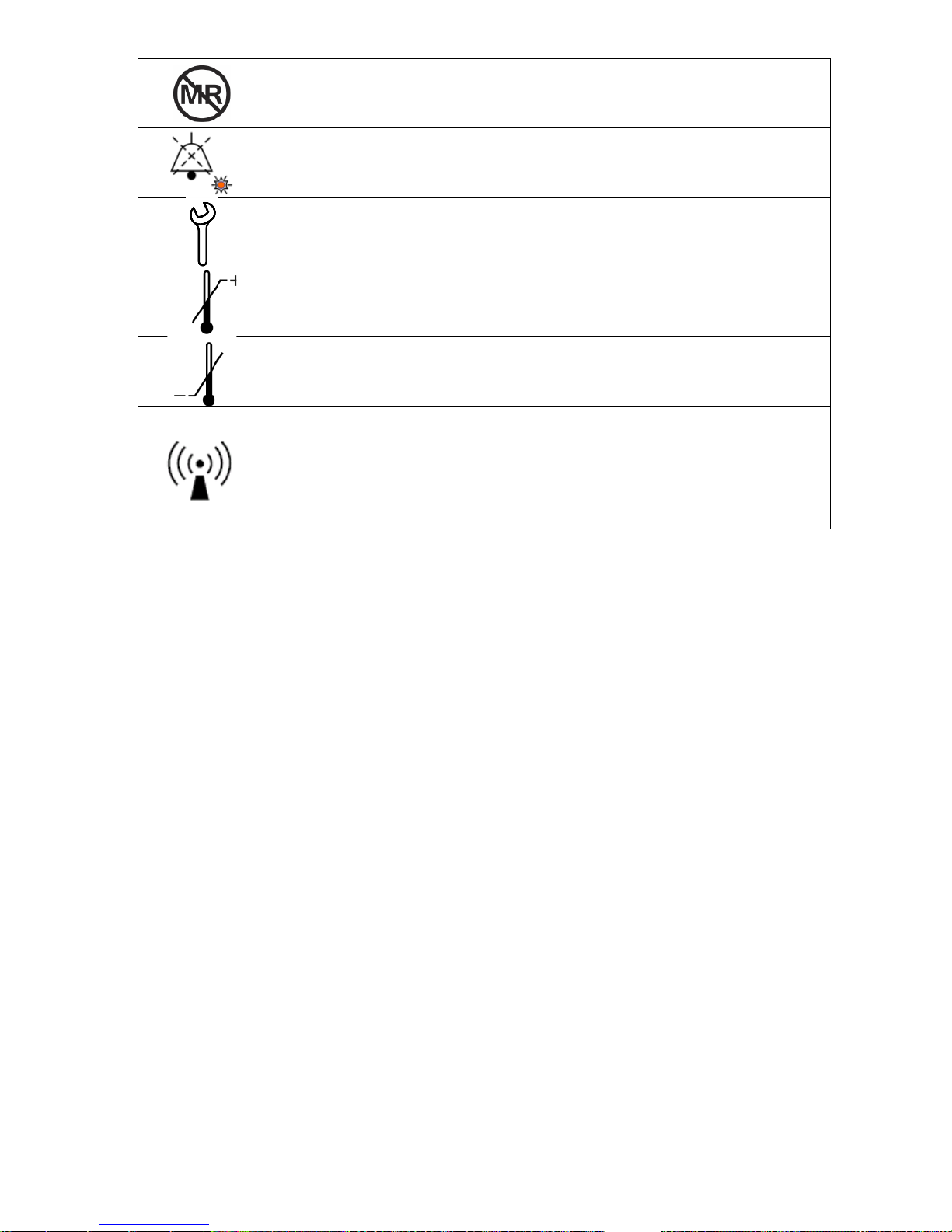
10
Not for use in MRI
Bell, cancel temporary
Service indicator
Upper limit of temperature
Lower limit of temperature
Non-ionizing electromagnetic radiation
Page 11
INT/R295-EN-PM/4-09/14
11
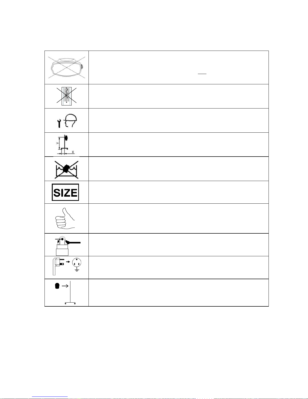
1.4 Mistral- Air® Graphics
This paragraph contains a list of Mistral-Air® graphics.
Prior to use, the user needs to check that the Mistral-Air® Plus
warming unit (including the power cord and the hose) is
undamaged. In the event of damage do not use the Mistral-Air®
Plus warming unit.
Do not use the Mistral-Air® blankets when damaged.
Maintenance and repairs shall be performed by qualified medical
instrument technicians only.
To keep the Mistral-Air® Plus warming unit stable, the wheelbase
of the stand must be in a particular ratio to the clamp height. See
chapter 7.
Do not immerse the Mistral-Air® Plus warming unit in fluid. Clean
the appliance with standard cleaning agents. See paragraph 11.
S = Small, M = Medium, L = Large, XL = Extra large
All steps are followed according to the manufacturer’s instructions
Make sure the power cord is secured by the cord anchor
Plug the unit into an earthed mains socket
Before using the Mistral-Air® Plus warming unit, it should be
attached to a pole or placed on a table.
Page 12

INT/R295-EN-PM/4-09/14
12
2 Indications For Use
The Mistral-Air Warming System is a forced air warming device and
comprises of a warming unit and a variety of blankets. It is intended to raise
and maintain patient temperature by means of surface warming.
3 Temperature Management
Hypothermia, an abnormal drop in body temperature, is a threat to human
life. Hospital patients in particular run serious risks if their body temperature
falls below 36 ºC. The risk of hypothermia is particularly high at moments
when they are vulnerable, such as pre-, per-, and post-surgical interventions.
Factors that can contribute to hypothermia include the duration of the
surgical intervention, the location of the wound, the amount of blood loss, the
surface area of the wound, the environmental temperature and the
anaesthetic technique.
4 Forced Air Warming
Forced air warming is a widely used and clinically accepted intervention for
the prevention of hypothermia and/or re-warming of the postoperative
surgical patient. The principle of operation for forced air warming systems is
an electrically powered unit consisting of a fan and heating element that
propels warmed air via a flexible hose to a blanket draped over the patient.
Some configurations allow for the patient to be placed on top of the blanket
or surrounded by a warming tube.
All of these forced air warming systems are intended to distribute warmed air
to the patient in a manner that is safe and effective.
5 Description of Mistral-Air® Plus Warming Unit
The Mistral-Air® Plus warming unit is a system which is intended for use in
preventing patients from becoming hypothermic.
The Mistral-Air® Plus warming unit shall only be used with disposable
Mistral-Air® blankets that are single patient use only.
Page 13
INT/R295-EN-PM/4-09/14
13
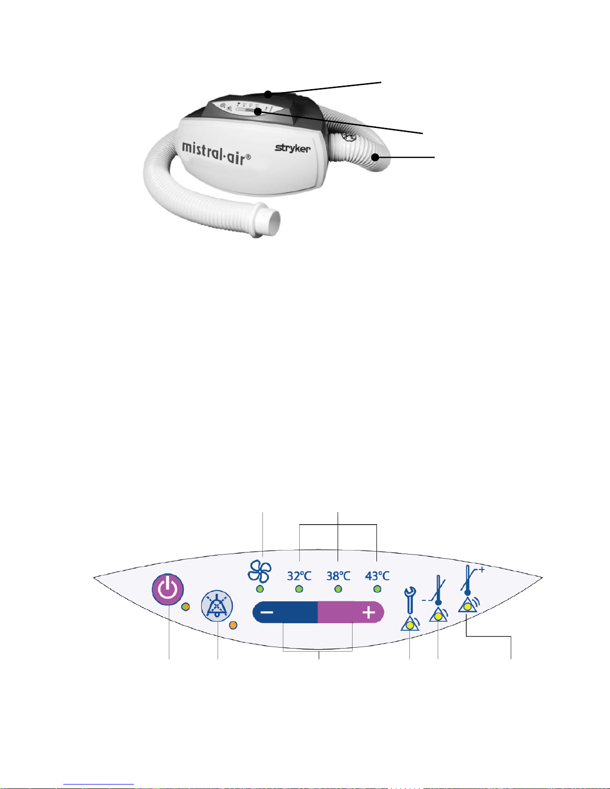
5.1 The Appliance
The Mistral-Air® Plus warming unit can be controlled by using the control
panel at the front top of the unit. The clamp to fix the Mistral-Air® Plus
warming unit to a pole is positioned at the back of the unit.
Article Number: MA1100-PM (110-120 V~, 60 Hz)
5.2 The Control Panel
The control panel is located at the front top of the unit and may be operated
by pressure sensitive buttons.
The Mistral-Air® Plus warming unit is very easy to use. All settings are visible
on the control panel and you can select the preferred temperature by
pressing the Temperature Selection button.
In emergencies, an audible alarm will be activated and an LED will flash
yellow.
Stand-by
button / On
Audible
alarm
suppression
button
Temperature
selection button
Service
indicator
Under temp
alarm
Over temp
alarm
Temperature selection
indicator
Fan only /
ambient air
indicator
Control panel
Hose towards
patient/blanket
Handle, at top side
Page 14
INT/R295-EN-PM/4-09/14
14
6 Preparing the Mistral-Air® Plus Warming Unit For
Use
Before using the Mistral-Air® Plus warming unit, it should be
attached to a pole or placed on a table.
Prior to use, the user needs to check that the Mistral-Air® Plus
warming unit, the power cord and the hose are undamaged. In the
event of damage do not use the Mistral-Air® Plus warming unit.
Plug the Mistral-Air® Plus warming unit into an earthed socket.
Place the unit in such way that the mains plug can be
disconnected easily in case of emergency.
The potential equalization plug at the rear of the device can be
connected to the hospital grounding system.
7 Mounting the Mistral-Air® Plus Warming Unit
The Mistral-Air® Plus warming unit must be mounted securely before use.
The Mistral-Air® Plus warming unit can be mounted onto the Mistral-Air®
curved pole MA5115A-PM with optional basket MA5120-PM.
The unit should be clamped onto the pole at the indentation.
Avoid blocking the air inlet (bottom of unit).
It is also possible to place the Mistral-Air® Plus warming unit on a table.
Do not place the unit in or on the bed with the patient
Page 15

INT/R295-EN-PM/4-09/14
15
8 User Instructions
When using the Mistral-Air® Plus warming unit, please follow the
instructions below. In each blanket box an instruction for use is added.
Check patient’s temperature and skin condition at least every 15
minutes.
Monitor patient skin routinely
Warming transdermal medications (patches) can increase drug
delivery, resulting in possible harm to the patient
Do not apply to patients with ischemic limbs.
8.1 Connection to Power Supply
a b c
d
a. Make sure the power cord is secured by the cord anchor.
b. Plug the unit into an earthed mains socket.
Mistral-Air® Curved Pole incl. Base
MA5115A-PM
Mistral-Air® Basket MA5120-PM
Page 16

INT/R295-EN-PM/4-09/14
16
c. The unit automatically switches to Stand-by mode, which is indicated by
the orange Stand-by LED located on the left side of the control panel.
d. The Mistral-Air® Plus warming unit is now in Stand-by mode.
To remove all power from the Mistral-Air® Plus warming unit, the
mains power cord must be removed from the electrical receptacle.
8.2 Switching the Unit On
a b c
a. Activate the Mistral-Air® Plus warming unit by pressing the Stand-by
button. The LED now turns green.
b. The Mistral-Air® Plus warming unit will now perform a self-test, which
includes a flash of all the LED’s and a short audible alarm. When a LED
or the audible beep fails, take the unit out of use for repair.
c. After passing the self-test The Mistral-Air® Plus warming unit will start
blowing air at the default temperature setting of 38 ˚C.
Stay in viewpoint of the user interface when performing the self-test,
and selecting the set-point.
Do not use the Mistral-Air® Plus warming unit without a
Mistral-Air® blanket connected to it. Thermal injury may
result.
8.3 Connecting the Blanket
Take the selected Mistral-Air® blanket out of the package and follow the
instructions on the insert provided with the blanket box.
Place the unit near the hose inlet of the blanket. Insert the end of the
flexible hose into the air inlet port of the Mistral-Air® blanket. Make sure the
hose is fully pushed in.
Page 17

INT/R295-EN-PM/4-09/14
17
8.4 Warming Up With the Mistral-Air Plus Warming Unit
8.4.1 Temperature settings
The four settings are:
Fan only - Ambient air
32 ºC (89.6ºF) - Low temperature
38 ºC (100.4ºF) - Medium temperature
43 ºC (109.4ºF) - High temperature
8.4.2 Temperature Selection
The Mistral-Air® Plus warming unit will start up with the default temperature
setting of 38 ºC.
By pressing the “–” temperature selection button twice (2x) (fan is selected
and the fan indicator turns green), the Mistral-Air® Plus will activate the unit
to draw in room temperature air and deliver it to the patient via the blanket.
The heater will not be activated.
The air temperature to the patient will depend on ambient conditions and
possible heat from the blower motor.
By pressing the “+” of the temperature selection button the Mistral-Air® Plus
will activate the heater to deliver the set temperature: 32 ºC, 38 ºC or 43 ºC
at the end of the hose.
By pressing the “+” of the temperature selecting button, the temperature
setting increases. This is indicated by a green LED:
By pressing the “-” of the Temperature Selecting Button, the temperature
setting decreases. This is indicated by a green LED:
Page 18

INT/R295-EN-PM/4-09/14
18
After selecting the desired temperature, the LED below the Temperature
Indicator will flash green. After reaching the set temperature (+ 2 ˚C) the
green flashing LED will light up permanently.
8.5 Stop Warming
a b c
a. Press the Stand-by button
b. Disconnect the hose from the blanket
c. If desired, leave the blanket on/under the patient
9 Safety Systems and Alarms
The Mistral-Air® Plus warming unit is equipped with visual and audible
safety systems to protect against over temperature and under temperature
conditions as well as to indicate that filter change is required.
In case of temperature alarm, check for free airflow. Ensure
blanket is not folded and do not place tools/equipment on the
blanket which could result in a blocked air flow. Be sure the air
inlet is free. If the unit continues to alarm, take the unit out of use
and contact the hospital service department or the local supplier.
9.1 General Alarms
If equipment emergencies occur, an audible alarm sounds and the relevant
LED(s) on the control panel will turn yellow. These safety systems are
described as follows:
A. Primary Over Temperature Alarm
This flashing yellow LED indicates an over temperature
condition of ≥ 45.5 ºC. The flashing LED will be accompanied by
a triple beep with an interval of 12.5 seconds. These alarms will
remain activated until the temperature falls below 45.5 ºC.
The heater shuts down; the unit tries to control the output
temperature to the set point. If this fails three times in a row, the
Page 19

INT/R295-EN-PM/4-09/14
19
heater and blower will shut down completely.
B. Secondary Over Temperature Alarm
This continuously burning yellow LED indicates an over
temperature condition:
Lower limit: > T
primary
Upper limit: ≤ 56.4 ºC
The flashing LED will be accompanied by a triple beep with an
interval of 12.5 seconds. If this occurs, the heater and blower
will shut down and control of the unit will not be restored until
the unit is powered off by disconnecting the mains plug and the
internal temperature sensor has been cooled down.
In case of a secondary over temperature alarm, check for hose
blockage.
In case of a repeated secondary over temperature alarm,
after resetting the unit, take the unit out of service and
contact Stryker Medical for technical support.
C. Under Temperature.
This yellow LED indicates an under temperature condition. It is
set to activate at 6 ºC under the set temperature. One single
beep is produced.
NOTE:
A broken temperature sensor or bad connection to the sensor
will result in an over temperature alarm. This applies for two
situations:
A defective sensor of the temperature controlling circuit
results in a primary over temperature alarm condition.
A defective sensor of the safety circuit results in a
secondary over temperature alarm condition.
9.2 Other Safety Features
D. Audible Alarm Suppression
The audible alarm may be suppressed for a short period by
pressing the Audible Alarm Suppression button. Audible alarm
suppression is indicated by a solid orange led. After the
interval of 2 minutes, or after pushing the button once again,
the audible alarm will automatically be activated again.
Page 20

INT/R295-EN-PM/4-09/14
20
E. Service Indicator
When the yellow LED under the wrench turns on, accompanied
by a single beep, the Mistral-Air® Plus warming unit has been
used for ≥ 2000 hours. This service indicator means that the
filter must be replaced. Reference Chapter 12 for filter
replacement instructions.
Alarm type
Alarm priorities
Service Indicator
Low priority
Under temperature alarm
Low Priority
(primary and secondary) Over
temperature alarm
Medium priority
9.3 The Blankets
Do not use the Mistral-Air® Plus warming unit with any forced air
disposables other than Mistral-Air® blankets. Thermal injury may
result.
The Mistral-Air Warming System is a forced air warming device and is
comprised of a warming unit and a variety of blankets. It is intended to raise
and maintain patient temperature by means of surface warming.
All Mistral-Air® blankets do not contain latex components and are:
Made from non-woven polypropylene and polyethylene
Manufactured to meet flammability standards
MR (Magnetic Resonance) Conditional (MA02XX-PM series, MA2XXX-PM series
and MA05XX-PM series only)
Non-conductive (electrical and thermal).
Non-sterile, except for several dedicated blankets (ask your distributor)
Blanket box including an instruction insert in the main world languages
Single-patient use only
Made from lightweight, soft materials that have been approved for skin
contact
Mistral-Air® blankets need to be used with the soft blue material
towards the patient’s skin and the white or reflective layer away from
the patient’s skin. The blue side provides the air distribution towards
the patient.
Never fold the blankets during use.
Page 21

INT/R295-EN-PM/4-09/14
21
Thermal injury may occur if heat is applied to ischemic limbs.
Do not obstruct blanket channels by e.g. instruments/tape/clamps.
10 Maintenance
It is recommended that Routine Maintenance be performed on an annual
basis for The Mistral-Air
Plus warming unit. Routine Maintenance or other
service shall only be performed by trained clinical or biomedical technicians
or engineers. Clinical users shall not repair or open the Mistral-Air
Plus
warming unit in the event of a malfunction. This can damage the appliance
and will invalidate the warranty. When the service indicator is activated, the
filter must be replaced.
Have the Mistral-Air® Plus warming unit serial number ready when you
contact the hospital service department or the local supplier for technical
support. The serial number is located on the side of the unit.
11 Storage and Cleaning
Store the Mistral-Air
Plus warming unit and its accessories in a cool and dry
place when not in use.
Disconnect from power when cleaning the Mistral-Air® Plus warming unit. Do
not use dripping wet cloths and do not allow water to seep into electrical
areas of the Mistral-Air
Plus warming unit.
Clean the unit by wiping the outer surface (including the hose) with a soft
cloth lightly dampened with a solution of water and mild detergent or a nonstaining hospital disinfectant.
Wipe all excess detergent or disinfectant from the unit and allow to air dry.
Do not use alcohol or acid based cleaners on the control panel.
Page 22

INT/R295-EN-PM/4-09/14
22
12 Replacing the Filter
The accumulation of dust in the air filter will reduce the efficiency of the
Mistral-Air® Plus warming unit. The filter shall be replaced as alerted by the
service indicator or when indicated by visual inspection. Only use parts
provided by Stryker Medical.
Step
Description
Image
1
Disconnect the unit from the power outlet
n.a.
2
Place the unit upside down
(be careful not to scratch the top cover)
3
Remove hose screw
4
Twist off hose clockwise
Page 23

INT/R295-EN-PM/4-09/14
23
5
Remove screws (3x) of filter screen
6
Remove filter screen
7
Remove filter
1. For disassembly follow steps 1-2 and 5-7 of this paragraph
2. Insert the new filter with the black seal towards the fan
3. For assembly follow steps 1-2 and 5-7 in reverse order
4. Reset the Hour Meter (see chapter 13)
Do not return the unit to service without the filter present.
Page 24

INT/R295-EN-PM/4-09/14
24
13 Reset the Hour Meter
The Mistral-Air® Plus warming unit is equipped with a built-in timer (hour
meter) that will activate the “service indicator” after ≥ 2000 hours of use.
This is an indication that replacement of the filter is required. After replacing
the filter, follow the steps below to reset the timer.
+
a B c d e
a) Switch unit in Stand-by mode.
b) Press and hold the “-”, “+” buttons and the Audible Alarm
Suppression button simultaneously.
c) While holding down the buttons, press the Stand-by button.
d) Now an audible alarm is produced and the unit returns to Stand-by
mode.
e) The hour meter has been reset successfully.
Page 25

INT/R295-EN-PM/4-09/14
25
14 Replacing the Hose
For disassembly follow steps 1-4 of Chapter 12. Apply the new hose by
twisting it firmly counter clockwise into place and apply the lock screw to
secure the hose.
Do not apply the lock screw into the sensor.
Note: when replacing the hose, do not touch the temperature sensor (see
image). If these sensors are touched in any way, the unit must be
recalibrated. Contact Stryker Medical for calibration service.
Temperature sensor plate
15 Replacing the Power Cord
a) Unplug the unit
b) Remove power cord from back of unit by unlocking the cord anchor:
c) Insert the new power cord and press it firmly into place.
d) Lock cord anchor:
Sensor
Page 26
INT/R295-EN-PM/4-09/14
26
16 Parts Replacement
The replacement procedures contained herein allow qualified medical
equipment persons to repair the Mistral-Air® Plus warming unit. Be sure to
contact Stryker Medical for all your replacement part needs before
servicing the unit. Service is available for this Mistral-Air® Plus warming unit
by contacting Stryker Medical.
High risk of accessible electrically live parts when removing the
hose!
17 Spare Parts and Order List
Part Number
Description
1
MA1100-1001-PM
Filter - SYK
2
MA1100-1018-PM
Hose - SYK
3
MA0115-PC-US-PM
Power cord – SYK
Please contact Stryker for the spare part list.
Page 27

INT/R295-EN-PM/4-09/14
27
18 Specifications
Article number
MA1100-PM
Voltage
110-120V~
Frequency
60 Hz
Current
6 A
Peak current
8.7 A
Peak power
925 W
Average power
550 W
Fuses
10AT/125V~/250V~
GMDN-code and term
P 36954 (Heating pad control unit, air)
47681 (Air heating/cooling pad, single-use, non-sterile)
47682 (Air heating/cooling pad, single-use, sterile)
Dimensions
10
7
8
⁄
inch x 15
1
4
⁄ inch x 9
3
8
⁄ inch (l x w x h)
Weight
+/- 13 lbs
Hose length
6 ft
Power cord length
13 ft
Filtration
HEPA, 0.3 µm, 99.99%, H13 conform EN 1822
Current leakage
< 50 µA
Classification 93/42/EEC
Class IIb
Classification IEC
60601-1
Class I, Body Floating (BF)
Classification IEC 60529
IP21
Ground resistance
< 0.2 Ω
Set point temperature
32 ºC, 38 ºC or 43 ºC & ambient temperature
Accuracy of temperature
± 2.5 ºC
Set point reached after
Maximum 2 minutes
Low temperature limit
6 ºC below set point
Maximum contact surface
temperature:
45.5 °C
Primary high temperature
Limit
≥ 45.5 ºC
Secondary high
temperature Limit
Lower limit: > T
primary
Upper limit: ≤ 56.4 ºC
Auditory alarm signal
sound pressure
54 dBA
Expected product life
time
7 year (Mistral-Air® Warming Unit)
Environmental conditions
Ambient temperature
10 ºC to 40 ºC
Relative humidity
30 % to 75 %
Atmospheric pressure
70 kPa to 106 kPa
Transport and storage conditions
Ambient temperature
- 40 ºC to 70 ºC
Relative humidity
10 % to 90 % (non-condensing)
Atmospheric pressure
50 kPa to 106 kPa
Page 28

INT/R295-EN-PM/4-09/14
28
19 Electromagnetic Compatibility
19.1 Electromagnetic immunity
Guidance and manufacture’s declaration - electromagnetic immunity
The Mistral-Air® plus warming unit is intended for use in an electromagnetic
environment specified below. The customer or the user of the Mistral-Air® Plus
warming unit should assure that it is used in such an environment.
Immunity test
IEC60601 test
level
Compliance
level
Electromagnetic
environment
guidance
Electromagnetic
discharge (ESD)
IEC 61000-4-2
±6 kV contact
±8 kV air
±6 kV contact
±8 kV air
Floors should be
wood, concrete or
ceramic tile. If floors
are covered with
synthetic material,
the relative humidity
should be at least
30%
Electrical fast
transient / burst
IEC 61000-4-4
±2 kV for power
supply lines
±1kV for
input/output
lines
±2 kV for power
supply lines
±1kV for
input/output
lines
Mains power quality
should be that of a
typical commercial
or hospital
environment.
Surge
IEC61000-4-5
±1 kV
differential
mode
±2 kV common
mode
±1 kV
differential
mode
±2 kV common
mode
Mains power quality
should be that of a
typical commercial
or hospital
environment.
Voltage dips, short
interruptions and
voltage variations
on power supply
input lines
IEC 61000-4-11
<5 % UT
(>95 % dip in UT
)
for 0.5 cycle
40 % UT
(60 % dip in UT )
for 5 cycles
70 % UT
(30 % dip in UT )
for 25 cycles
<5 % UT
<5 % UT
(>95 % dip in UT
)
for 0.5 cycle
40 % UT
(60 % dip in UT )
for 5 cycles
70 % UT
(30 % dip in UT )
for 25 cycles
<5 % UT
Mains power quality
should be that of a
typical commercial
or hospital
environment. If the
user of the MistralAir® plus warming
unit requires
continued operations
during power mains
interruptions, it is
recommended that
the Mistral-Air® plus
warming unit be
Page 29

INT/R295-EN-PM/4-09/14
29
(>95 % dip in UT
)
for 5 sec
(>95 % dip in UT
)
for 5 sec
powered from an
uninterruptible power
supply or a backup
battery system.
Power frequency
(50/60 Hz)
magnetic field
IEC 61000-4-8
3 A/m
3 A/m
Power frequency
magnetic fields
should be at levels
characteristic of a
typical location in a
typical commercial
or hospital
environment.
NOTE: UT is the a.c. mains voltage prior to application of the test level.
Conducted RF
IEC61000-4-6
Radiated RF
IEC61000-4-3
3 Vrms
150 kHz to 80
MHz
3 V/m
80 MHz to 2.5
GHz
3 Vrms
3 V/m
Portable and mobile
RF communications
equipment should
not be used any
closer to any part of
the Mistral-Air® plus
warming unit,
including cables,
than the
recommended
separation distance
calculated from the
equation applicable
to the frequency of
the transmitter.
Recommended
separation distance
d = 1.2 √ P
d = 1.2 √ P 80 MHz
to 800 MHz
d = 2.3 √ P 800 MHz
to 2.5 GHz
where P is the
maximum output
power rating of the
transmitter in watts
(W) according to the
transmitter
Page 30

INT/R295-EN-PM/4-09/14
30
manufacturer and d
is the recommended
separation distance
in meters (m).
Field strengths from
fixed RF
transmitters, as
determined by an
electromagnetic site
surveya, should be
less than the
compliance level in
each frequency
rangeb.
Interference may
occur in the vicinity
of equipment
marked with the
following symbol:
NOTE 1 At 80 MHz and 800 MHz, the higher frequency range applies.
NOTE 2 These guidelines may not apply in all situations. Electromagnetic
propagation is affected by absorption and reflection from structures, objects and
people.
a
Field strengths from fixed transmitters, such as base stations for radio
(cellular/cordless) telephones and land mobile radios, amateur radio, AM and FM
radio broadcast and TV broadcast cannot be predicted theoretically with
accuracy. To assess the electromagnetic environment due to fixed RF
transmitters, an electromagnetic site survey should be considered. If the
measured filed strength in the location in which the Mistral-Air® Plus warming unit
is used exceeds the applicable RF compliance level above, the Mistral-Air® Plus
warming unit should be observed to verify normal operations. If abnormal
performance is observed, additional measures may be necessary, such as
reorienting or relocating the Mistral-Air® Plus warming unit.
b
Over the frequency range 150 kHz to 80 MHz, filed strengths should be less
than 3 V/m
Page 31

INT/R295-EN-PM/4-09/14
31
19.2 Electromagnetic Emissions
Guidance and manufacture’s declaration – electromagnetic emissions
The Mistral-Air® Plus warming unit is intended for use in an electromagnetic
environment specified below. The customer or the user of the Mistral-Air® plus
warming unit should assure that it is used in such an environment.
Emissions Test
Compliance
Electromagnetic environment –
guidance
RF emissions
CISPR 11
Group 1
The Mistral-Air® Plus uses RF
energy only for its internal
function. Therefore, its RF
emissions are very low and are
not likely to cause any
interference in nearby electronic
equipment
RF emissions
CISPR 11
Class B
The Mistral-Air® Plus is suitable
for use in all establishments,
including domestic
establishments and those directly
connected to the public lowvoltage power supply network
that supplies buildings used for
domestic purposes.
Harmonic emissions
IEC61000-3-2
Class A
Voltage fluctuations/
flicker emissions
IEC61000-3-3
Complies
Page 32
INT/R295-EN-PM/4-09/14
32
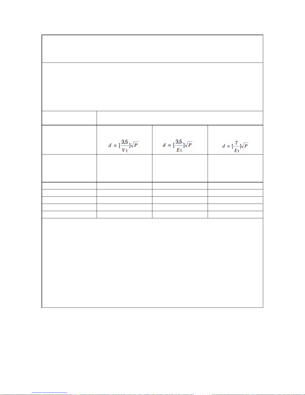
19.3 Recommended Separations Distances
Recommended separation distances between portable and mobile RF
communications equipment and the Mistral-Air® Plus warming unit
The Mistral-Air® Plus warming unit is intended for use in an electromagnetic
environment in which radiated RF disturbances are controlled. The customer or
the user of the Mistral-Air® Plus warming unit can help prevent electromagnetic
interference by maintaining a minimum distance between portable and mobile
RF communications equipment (transmitters) and the Mistral-Air® Plus warming
unit as recommended below, according to the maximum output power of the
communications equipment.
Separation distance according to frequency of transmitter
m
Rated maximum
output power
of transmitter
W
150 kHz to 80
MHz
80 MHz to 800
MHz
800 MHz to 2,5
GHz
Rated maximum
output power
of transmitter
W
150 kHz to 80
MHz
80 MHz to 800
MHz
800 MHz to 2,5
GHz
0.01
0.12
0.12
0.24
0.1
0.37
0.37
0.74
1
1.17
1.17
2.34
10
3.69
3.69
7.38
100
11.67
11.67
23.34
For transmitters rated at a maximum output power not listed above, the
recommended separation distance d in metres (m) can be estimated using the
equation applicable to the frequency of the transmitter, where P is the maximum
output power rating of the transmitter in watts (W) according to the transmitter
manufacturer.
NOTE 1 At 80 MHz and 800 MHz, the separation distance for the higher
frequency range applies.
NOTE 2 These guidelines may not apply in all situations. Electromagnetic
propagation is affected by absorption and reflection from structures, objects and
people.
Page 33

INT/R295-EN-PM/4-09/14
33
20 Warranty
Please contact Stryker Medical Customer Service or your Stryker Medical
sales representative for warranty related questions. Contact information is
located on the last page of this manual.
Page 34

INT/R295-EN-PM/4-09/14
34
Partner in Patient Temperature Management
The 37Company is a leading European company in the field of hypothermia and
offers a complete range of innovative solutions for patient temperature
management.
The Surgical Company International B.V.
Beeldschermweg 6F
3821 AH Amersfoort
The Netherlands
www.the37company.com
The 37Company is member of The Surgical Company Group
Distributed by:
Stryker Medical
3800 E. Centre Ave.
Portage, Michigan 49002
USA
(800) 327-0770
 Loading...