

Page 1

S3™ MedSurg Bed
Model 3002
Patriot™ Series
Operations Manual
For parts or technical assistance call:
1-800-327-0770
2011/03 3006-109-101 REV A.2 www.stryker.com
Page 2

Page 3

Table of Contents
Symbols and Definitions .....................................................................5
Warning/Caution/Note Definition ............................................................6
Introduction ..............................................................................7
Intended Use – Stryker S3™ ..............................................................7
Intended Use – iBed® Wireless with iBed® Awareness............................................7
Specifications .........................................................................7
Mattress Specifications ..................................................................8
Environmental Conditions.................................................................8
Product Illustration......................................................................9
Contact Information ....................................................................10
Serial Number Location .................................................................10
Summary of Safety Precautions ..............................................................11
iBed® Awareness Option ................................................................13
iBed® Wireless Option .................................................................. 13
115V Option .........................................................................14
Setup Procedures.........................................................................15
iBed® Wireless Option ..................................................................16
Base Operation Guide .....................................................................17
Brake Pedal Operation..................................................................17
Steer Pedal Operation ..................................................................17
Litter Operation Guide .....................................................................18
CPR Emergency Release ................................................................18
Foot Prop Usage ......................................................................18
Fracture Frame Usage ..................................................................18
Foley Bag Hooks Usage ................................................................. 18
Positioning Siderails....................................................................19
Control Panel Lights....................................................................19
Operating I.V. Poles ....................................................................20
Night Light Usage .....................................................................21
Nurse Call Backup Battery (Optional) .......................................................21
1/4” Nurse Call Port (Optional) ............................................................21
Using the 115 Volt Outlet (Optional) ........................................................21
CPR Board Usage (Optional Equipment) .....................................................21
Siderail Operation Guide....................................................................22
Nurse Control Functions (Outside Siderail) ...................................................22
Patient Control Functions without Optional Smart TV (Inside Siderail) ...............................23
Patient Control Functions with Optional Smart TV (Inside Siderail)..................................24
Patient TV Channel Control Functions with Optional Smart TV (Inside Siderail) . . . . . . . . . . . . . . . . . . . . . . . . 25
Footboard Operation Guide..................................................................26
Intended Use .........................................................................26
Footboard Control Panel Buttons ..........................................................26
Footboard Control Panel Functions .........................................................27
LED Indicators: Footboard ...............................................................29
Display Screens.......................................................................31
www.stryker.com 30 06 -109-101 REV A 3
Page 4

Table of Contents
Footboard Operation Guide (Continued)
Optional Chaperone Bed Exit .............................................................32
Chaperone Bed Exit with Zone Control ......................................................33
Optional Scale System..................................................................34
iBed® Awareness Functionality ............................................................40
iBed® Awareness Light Bar and Side Lights ..................................................40
iBed® Awareness ON/OFF Button..........................................................40
iBed® Awareness Monitoring and Alarms ....................................................41
Low Height .......................................................................41
Brakes...........................................................................41
Siderails .........................................................................41
Bed Exit..........................................................................42
Fowler 300+ Lock...................................................................42
Additional Alarm Conditions ...........................................................42
®
Awareness Locks .................................................................43
iBed
Fowler 300+ Lock Button ............................................................43
Bed Motion Lock ...................................................................43
Patient Control Locks ................................................................43
Optional Pendant Operation Guide ............................................................44
Pendant - Motion/Nurse Call (3006-315-011)..................................................44
Pendant - Motion/Nurse Call/Smart Tv (Digital) (3006-315-012)....................................44
Optional Infrared (IR) Module ................................................................45
Optional iBed Locator......................................................................46
Preventative Maintenance ...................................................................48
Checklist ............................................................................48
Grease Points ........................................................................49
Product Labels ...........................................................................50
Cleaning................................................................................60
Recycling Passport .......................................................................61
EMC Information..........................................................................70
Warranty ...............................................................................74
Limited Warranty ......................................................................74
To Obtain Parts and Service .............................................................74
Service Contract Coverage ..............................................................74
Service Contract Programs ..............................................................75
Return Authorization
Damaged Merchandise .................................................................75
International Warranty Clause.............................................................75
....................................................................75
4 30 06-10 9-101 RE V A www.stryker.com
Page 5
Symbols and Definitions
~
X
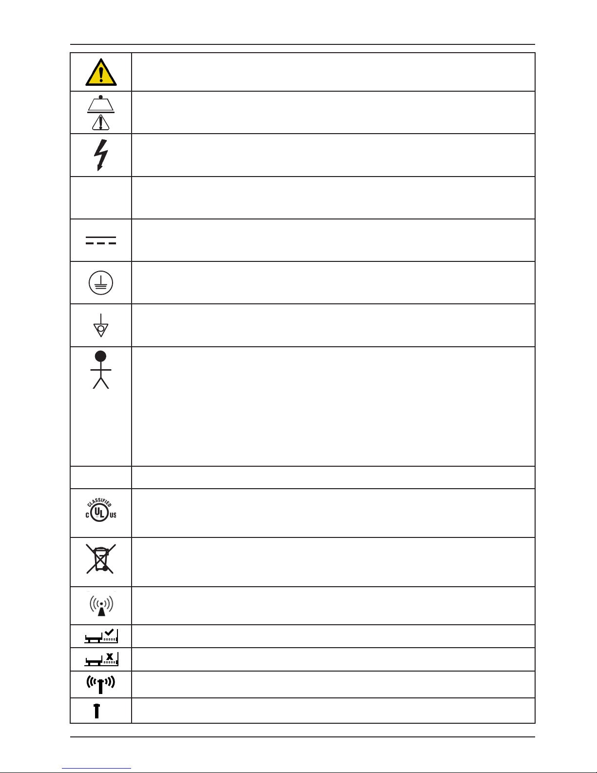
Warning, consult accompanying documentation
Safe Working Load Symbol
Dangerous Voltage Symbol
Alternating Current
Direct Current
Protective Earth Terminal
IPX4
Potential Equalization Symbol
Type B Equipment: equipment providing a particular degree of protection against electric shock,
particularly regarding allowable leakage current and reliability of the protective earth connection.
Class 1 Equipment: equipment in which protection against electric shock does not rely on BASIC
INSULATION only, but which includes an additional safety precaution in that means are provided
for the connection of the EQUIPMENT to the protective earth conductor in the fixed wiring of the
installation in such a way that ACCESSIBLE METAL PARTS cannot become live in the event of a
failure of the BASIC INSULATION.
Mode of Operation: Continuous
Protection from liquid splash
Medical Equipment Classified by Underwriters Laboratories Inc. with Respect to Electric Shock, Fire,
Mechanical and Other Specified Hazards Only in Accordance with UL 60601−1, First Edition (2003)
and CAN/CSA C22.2 No. 601.1−M90 with updates 1 and 2 and IEC 60601-1 (1998) with Amendment
1 (1991) and Amendment 2 (1995).
In accordance with European Directive 2002/96/EC on Waste Electrical and Electronic Equipment,
this symbol indicates that the product must not be disposed of as unsorted municipal waste, but
should be collected separately. Refer to your local distributor for return and/or collection systems
available in your country.
Non-ionizing radiation; i.e. RF transmitter (WiFi)
This icon means the iBed Locator is connected.
X
This icon means the iBed Locator is not connected.
This icon means the Network is connected.
This icon means the Network is not connected.
www.stryker.com 30 06 -109-101 REV A 5
Return To Table of Contents
Page 6

Symbols and Definitions
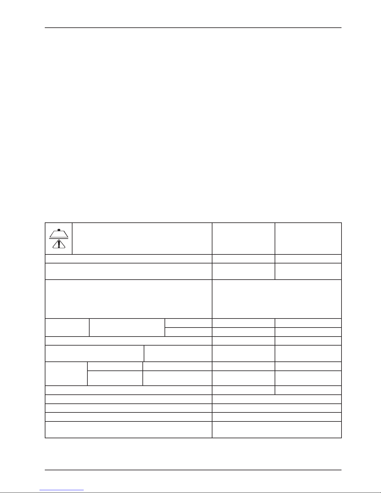
WARNING/CAUTION/NOTE DEFINITION
The words Warning, Caution and Note carry special meanings and should be carefully reviewed.
WARNING
Alerts the reader about a situation, which if not avoided, could result in death or serious injury. It may also describe
potential serious adverse reactions and safety hazards.
CAUTION
Alerts the reader of a potentially hazardous situation, which if not avoided, may result in minor or moderate injury to
the user or patient or damage to the equipment or other property. This includes special care necessary for the safe
and effective use of the device and the care necessary to avoid damage to a device that may occur as a result of use
or misuse.
Note
This provides special information to make maintenance easier or important instructions clearer.
Return To Table of Contents
6 30 06-10 9-101 RE V A www.stryker.com
Page 7
Introduction
This manual is designed to assist you with the operations of the S3™ MedSurg Bed, Model 3002 Patriot™ Series. Read
it thoroughly before using the equipment.
INTENDED USE – STRYKER S3™
This device is an AC-powered adjustable hospital bed intended for medical purposes that consists of a bed with a
built-in motor and remote controls that can be operated by the patient to adjust the height and surface contour of the
bed. The device includes movable and latchable siderails.
INTENDED USE – iBED® WIRELESS WITH iBED® AWARENESS
The intended use for the iBed® Wireless (with iBed® Awareness) is to assist clinical staff to monitor bed parameters
on specific Stryker beds. The desired bed parameters will be set by clinicians at the bedside. The iBed® Wireless
software is intended to be used only with specifically enabled Stryker beds that have been verified and validated with
the iBed® Wireless software, and is not intended to provide bed status information for non-Stryker beds. The iBed®
Wireless software is not intended to communicate any patient status information, nor to permanently store any type
of data. The iBed® Wireless with iBed® Awareness System is not intended to provide automated treatment decisions
or as a substitute for professional healthcare judgment. The iBed® Wireless with iBed® Awareness System is not a
replacement or substitute for vital signs monitoring or alert equipment. All patient medical diagnosis and treatment are
to be performed under direct supervision and oversight of an appropriate health care professional.
SPECIFICATIONS
Safe Working Load
Note: Safe Working Load indicates the sum of the
patient, mattress, and accessory weight.
Bed Weight 570 lbs 259 kg
Scale System Capacity (optional equipment). Loads weighing up to
Scale System Accuracy (optional equipment) ± 2 pounds at 0° - ± 10° Trendelenburg for patients
weighing 100 pounds or less
± 2% of the total patient weight at 0° - ± 10°
Trendelenburg for patients weighing greater than
100 pounds
Overall Length/
Width
Patient Sleep Surface - Standard Bed 84” x 35” 213.4 cm x 88.9 cm
Bed Height to Top of Seat
Litter - 6” Casters
Litter Platform
to Top of
Siderail
Space Between Siderails (Full Up) 2-1/4” 5.72 cm
Knee Gatch Angle 0° to 45°
Fowler Angle 0° to 60°
Trendelenburg/Reverse Trendelenburg +12° to -10° ± 1°
Electrical Requirements - all electrical requirements meet
UL 2601 specifications.
Standard Bed Siderails Up 93” x 41-1/2” 236.2 cm x 105.41 cm
Siderails Down 93” x 39-1/2” 236.2 cm x 100.3 cm
Standard 16” to 30” ±0.5 40.6 cm to 76.2 cm
Full Up Head End Siderail 15” 38.1 cm
Full Up Foot End Siderail 15 -1/2” 39.37 cm
115VAC, 60Hz, 8A
500 lbs 227 kg
500 lbs 227 kg
www.stryker.com 30 06 -109-101 REV A 7
Return To Table of Contents
Page 8

Introduction
Wireless Radio (iBed® Wireless Option) 802.11 b/g, 2.4 GHz
• Minimum Operational Signal Strength: -65 dB
• Supported Securities:
WEP
WPA-PSK (TKIP)
WPA 2- PS K (CCMP/AES)
• Supports IPv4 and DHCPv4
Outlet Option 115VAC, 60Hz, 10A
Battery Voltage (1) 9V - Nurse Call Option (Alkaline Battery)
Noise Level > 65dB
MATTRESS SPECIFICATIONS
Thickness 6” 15. 2 cm
Width >= 35” >= 88.9 cm
Length >= 84” >= 213.4 cm
ILD 80 lbs 36.3 kg
The above stated mattress specifications assist in ensuring the product conforms to HBSW and IEC specifications.
ENVIRONMENTAL CONDITIONS
Environmental Conditions Operation Storage and Transportation
0
F
104
0
C)
Ambient Temperature
50 0F
(10
0
C)
(40
-22 0F
(-30
0
C)
75%
Relative Humidity
(Non-Condensing)
30%
10%
1060 hPa
Atmospheric Pressure
700 hPa
500 hPa
Stryker reserves the right to change specifications without notice.
Specifications listed are approximate and may vary slightly from unit to unit or by power supply fluctuations.
140
(60
95%
1060 hPa
0
F
0
C)
Return To Table of Contents
8 30 06-10 9-101 RE V A www.stryker.com
Page 9
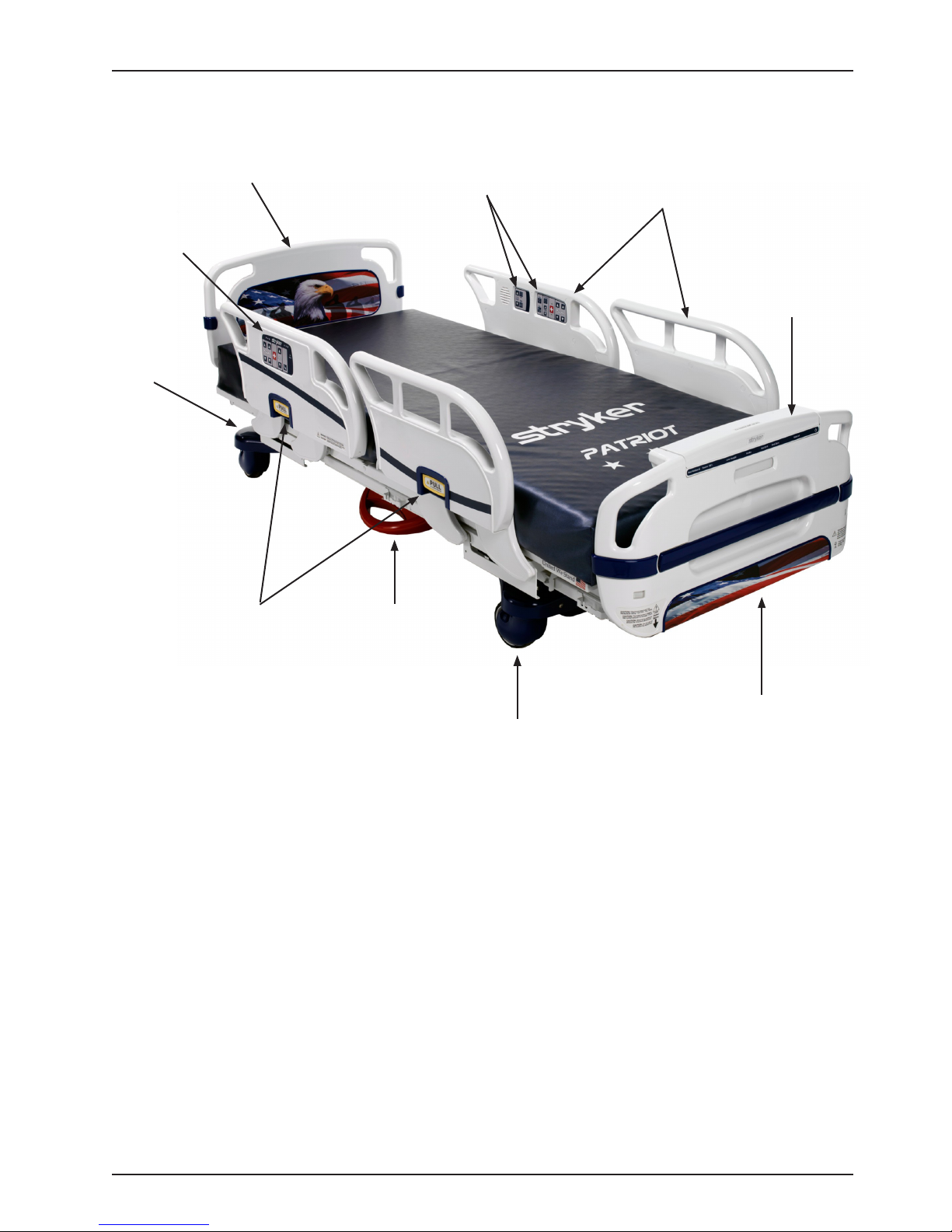
PRODUCT ILLUSTRATION
Introduction
Control Panel
Steer
Pedal
(no t
shown)
Nurse
Siderail Release
Headboard
Handle
Brake
Pedal
Patient
Control Panel
Siderail
Footboard
Control Panel
Caster
Footboard
www.stryker.com 30 06 -109-101 REV A 9
Return To Table of Contents
Page 10
Introduction
CONTACT INFORMATION
Contact Stryker Customer Service or Technical Support at (800) 327-0770.
Stryker Medical
3800 E. Centre Avenue
Portage, Michigan 49002
USA
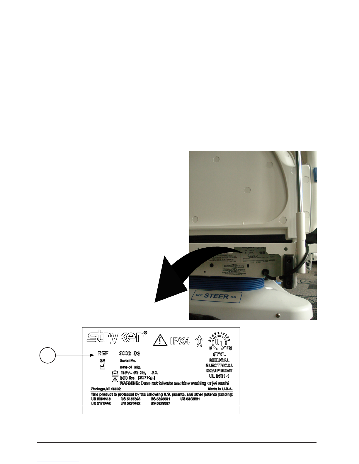
Please have the serial number (A) of your Stryker product available when calling Stryker Customer Service or Technical
Support. Include the serial number in all written communication.
SERIAL NUMBER LOCATION
The serial number is located at the head end of the
bed just below the headboard and above the power
cord where it comes out from the frame.
Head End of Bed
A
Return To Table of Contents
10 300 6-109 -101 REV A www.stryker.com
Page 11

Summary of Safety Precautions
Before operating the S3™ MedSurg Bed, Model 3002 Patriot™ Series, it is important to read and understand all
information in this manual. Carefully read and strictly follow the safety guidelines listed on this page. It is important
that all users have been trained and educated on the inherent hazards associated with the usage of electric beds.
WARNING
• Powered bed mechanisms can cause serious injury. Operate bed only with persons clear of mechanisms.
• Danger: Explosion hazard. Do not use in the presence of flammable anesthetics.
• Always apply the caster brakes when a patient is getting on or off the bed.
• Always keep the caster brakes applied when a patient is on the bed (except during transport). After the brake
pedal is applied, push on the bed to ensure the brakes are locked. Serious injury could result if the bed moves
while a patient is getting in or out of bed.
• Ensure the brakes are completely released prior to moving the unit. Attempting to move the unit with the brakes
actuated could result in injury to the user and/or patient.
• Do not attempt to move the foot end of the bed laterally when the steer pedal is activated. When the steer pedal
is activated, the steer caster at the foot end of the bed cannot swivel. Attempting to move the bed laterally when
the steer pedal is activated may cause injury to the user.
• The S3™ MedSurg Bed, Model 3002 Patriot™ Series is not intended for use with patients less than two years of
age.
• Serious injury can result if caution is not used when operating the unit. Operate the unit only when all persons are
clear of the electrical and mechanical systems.
• To help reduce the number and severity of falls by patients, always leave the bed in the lowest position when the
patient is unattended.
• When attaching equipment to the frame, ensure it will not impede normal frame operation. For example: hooks
on hanging equipment must not actuate control buttons, equipment must not hide the nurse call button, foley bags
must not rest on brake pedal, etc. Use only a Stryker supplied interface cable. Use of any other cable may cause
the bed to function improperly, which may result in patient or user injury.
• The S3™ MedSurg Bed, Model 3002 Patriot™ Series is equipped with a hospital grade plug for protection against
electric shock hazard. It must be plugged directly into a properly grounded three prong receptacle. Grounding
reliability can be achieved only when a hospital grade receptacle is used.
• When raising the siderails, listen for the “click”. When raising the siderail, the first click will indicate you can return
to the intermediate position, the second click indicates the full up position. Once in position, move the siderail
from side to side to ensure it is locked into position. Siderails are not intended to be a patient restraint device. It
is the responsibility of attending medical personnel to determine the degree of restraint and the siderail positioning
to ensure a patient will remain safely in bed.
• The Bed Exit System is intended only to aid in the detection of a patient exiting the unit. It is NOT intended
to replace patient monitoring protocol. The bed exit system signals when a patient is about to exit. Adding or
subtracting objects from the frame after zeroing the weigh system may cause a reduction in the sensitivity of the
bed exit system.
• Before servicing or cleaning the bed, always unplug the bed power cord from the wall socket and push the battery
power on/off switch to the “OFF” position (if applicable). When working under a bed in the high position, always
place blocks under the litter frame and apply the brakes to prevent injury in case the Bed Down switch is accidently
pressed.
• To avoid pinching your fingers, place the I.V. pole in the upright position before using the drive handle.
• When using any mattress and/or mattress overlay that increases the overall height greater than 6,” extra caution
and/or operator supervision is required to help reduce the likelihood of a patient fall occurring.
• When a Patient’s condition (such as disorientation due to medication or clinical condition) could lead to patient
entrapment, the mattress support platform should be left in the flat position while the patient is unattended (except
when required otherwise my medical staff for special or particular circumstances).
• Trendelenburg is not easily achievable when mains voltage has been interrupted.
• Medical electrical equipment (i.e. Optional Scale System) requires special precautions regarding EMC and needs
to be installed and put into service according to the EMC information provided on page 70 to prevent equipment
malfunction.
• Portable and mobile RF communication equipment can affect Medical Electrical Equipment (i.e. Optional Scale
System).
www.stryker.com 30 06 -109-101 REV A 11
Return To Table of Contents
Page 12

Summary of Safety Precautions
WARNING CONTINUED
• To avoid malfunction, the Optional Scale System should not be used adjacent to or stacked with other equipment.
If adjacent or stacked use is necessary, the Optional Scale System should be observed to verify normal operation
in the configuration in which it will be used.
To avoid possible injury and to assure proper operation when using model number 2750, 2920, 2950 or 2981 mattress:
• Confirm proper scale system operation following mattress installation. For best results, secure the therapy mattress
power cord to prevent damage to the cord or interference with the bed frame and the scale system.
• Do not zero bed scales or weigh patient with Percussion, Vibration, Rotation or Turn Assist active. Patient motion
and position resulting from the dynamic therapy mattress may adversely affect scale system performance.
• Do no initialize (“arm”) bed exit with Percussion, Vibration, Rotation or Turn Assist active. The patient motion and
position resulting from the dynamic therapy mattress may adversely affect bed exit system performance.
• When using an XPRT (2950), Position PRO (2920), Impression (2981) or Symmetric Aire (2750) mattress, extra
caution and/or operator supervision is required to help reduce the likelihood of a patient fall occurring.
CAUTION
• Unplug bed during service or cleaning.
• When large spills occur in the area of the circuit boards, 120 volt cables and motors, immediately unplug the bed
power cord from the wall socket. Remove the patient from the bed and clean up the fluid. Have maintenance completely check the bed. Fluids can affect the operational capabilities of any electrical product. DO NOT put the bed
back into service until it is completely dry and has been thoroughly tested for safe operation.
• Preventative maintenance should be performed at a minimum of annually to ensure all bed features are functioning
properly. Close attention should be gi ven to safety features including, but not limited to, safety side latching mechanisms,
frayed electrical cords and components, all electrical controls returning to the off or neutral position when released,
caster braking systems, no controls or cabling entangled in bed mechanisms, leakage current 300 μA (microamps)
maximum, scale and bed exit systems calibrated properly, and the siderail gas spring not leaking oil.
• Because individual beds may have different options, footboards should not be moved from one bed to another.
Mixing footboards could result in unpredictable bed operation.
• The lockout buttons on the footboard lock the Fowler, Gatch and Bed Up/Down functions and prevent motion of the
bed. It is the responsibility of attending medical personnel to determine whether these functions should be locked
and to use the buttons accordingly.
• The maximum safe working load for each I.V. pole is 40 pounds.
• I.V. Poles should not be used as a bed push/pull device.
• Scale function may be affected by siderail/caster interference. With the litter fully lowered or lowered in Reverse
Trendelenburg, the siderails tucked under the litter in the storage position and the casters turned, there is the
potential for interference between the siderail and the caster. Raise the siderails when lowering the litter to the full
down position to prevent the interference from causing the scale system to weigh inaccurately.
• The use of a mattress overlay may reduce the effectiveness of the siderail.
• The cleanliness and integrity of both ground chains must be maintained to minimize static build up and discharge.
• Do not add or remove weight when the bed exit system is armed.
• There is a possible fire hazard when using half bed length type oxygen administering equipment. Ensure the
siderails are outside of the tent.
• There is a possible fire hazard when used with oxygen administering equipment of other than the nasal or mask
type. Lock the control at foot of bed when using oxygen administering equipment.
• The weight of the foley bags placed on isolated bag hooks should not exceed five pounds.
• The weight of pumps placed on footboard pump holder should not exceed 45 pounds.
• The safe working load of the defibrillator tray is 40 lbs.
• The safe working load of the oxygen holder is 45 lbs.
• Bed may be equipped with an integrated scale intended to weigh the patient in bed. If the scale output is being
used to determine diagnosis and treatment, please consult with a medical professional and/or additional weight
references.
• Scale accuracy specifications do not apply for patients under 20 lbs.
Return To Table of Contents
12 3006 -109 -101 R EV A www.stryker.com
Page 13

Summary of Safety Precautions
IBED® AWARENESS OPTION
In addition to the previous warnings and cautions, all of the following warnings and cautions apply to units equipped
with the iBed® Awareness option.
WARNING
• The optional iBed® Awareness system only indicates the siderail position, it does NOT indicate if the siderail is
locked. It is the caregiver’s responsibility to ensure that the siderails are locked after every move and also before
leaving a patient in the room.
• The optional iBed® Awareness system indicator lights are only an aid to the caregiver, and in no way replace the
caregiver’s responsibility of checking on patients. Caregivers should not rely on the lights to perform their duties.
• Before arming the optional iBed® Awareness system, the nurse must physically verify that the siderails are locked.
CAUTION
• If the optional iBed® Awareness system is being used, ensure the bed is in the desirable state (iBed® Awareness
ON and with the light green) before leaving the room.
• If the optional iBed
Awareness as the display information to troubleshoot the bed will get lost.
• If the optional iBed® Awareness system is being used, use of accessories that cover the center and side alert lights
at the footboard are not recommended.
®
Awareness system is being used and the iBed® Awareness is alerting, do not turn off iBed®
iBED® WIRELESS OPTION
In addition to the previous warnings and cautions, all of the following warnings and cautions apply to units equipped
with the iBed® Wireless option.
WARNING
• The optional iBed® Wireless function provides remote information of bedside information to aid the caregiver. In
no way does this option replace the caregiver’s responsibility of checking on patients. Caregivers should not rely
only on the remote information to perform their duties.
• The iBed Locator must be correctly associated or mapped to the room / location in order to provide accurate
location information. Failure to properly map the iBed Locator to the room / location will yield incorrect remote
information. Additionally, if an iBed Locator is to be moved after it has been installed and mapped, it must be remapped to the new room / location in which it is moved to. iBed Locator re-mapping will also be required if the
room / location information is changed after initial installation.
• Line of sight between iBed Locator and the head end of bed must be free of obstruction at all times. Any line
of sight interference could impede communication and cause the room / location information not to be available.
• iBed® Wireless compatible footboard must be used for all iBed® Wireless beds. Some iBed® Wireless functionality
will be lost if an older version of the footboard is used.
• iBed
• iBed Locators must be installed more than 71” apart from one another in the same room, such as in a semi-private
®
Wireless functionality shall be verified after installation. Failure to do may result loss of remote information
or wrong remote information. At a minimum, verify iBed locator communication with bed in all bed positions, and
iBed® Wireless communication with the wireless access point.
room with more than one bed. Failure to do so could result in a bed communicating with the other adjacent iBed
Locator, thus providing incorrect bed location information.
CAUTION
• Wireless bed only transmits bed information and not nurse call information. The wireless bed is not intended to
replace the existing nurse call system.
www.stryker.com 30 06 -109-101 REV A 13
Return To Table of Contents
Page 14

Summary of Safety Precautions
115V OPTION
In addition to the previous warnings and cautions, all of the following warnings and cautions apply to units equipped
with the 115V option.
• Only use equipment with the following electrical specs: 115VAC; 10A; 60Hz. Maximum total load drawn by
equipment used in this receptacle outlet must not exceed 10A. The total system chassis risk current should not
exceed 100 μA (microamps). Grounding continuity should be checked periodically.
• To avoid risk of electrical shock, unplug all power cords before opening the service compartment, junction box or
receptacle.
• Do not use the optional 115V outlet for life sustaining equipment.
Return To Table of Contents
14 30 06 -109-101 REV A www.stryker.com
Page 15

Setup Procedures
To prevent permanent damage to this unit, the unit must reach room temperature prior to conducting any setup
and/or unit operations.
It is important that the S3™ MedSurg Bed, Model 3002 Patriot™ Series is working properly before it is put into service.
The following list will help ensure that each part of the bed is tested.
WARNING
• The S3™ MedSurg Bed, Model 3002 Patriot™ Series is equipped with a hospital grade plug for protection against
electric shock hazard. It must be plugged directly into a properly grounded three prong receptacle. Grounding
reliability can be achieved only when a hospital grade receptacle is used.
• Use only a Stryker supplied interface cable. Use of any other cable may cause the bed to function improperly
which may result in patient or user injury.
1. Plug the bed into a properly grounded, hospital grade wall receptacle and ensure the LED light at the foot
end of the bed comes on.
2. Plug the optional interface cable into the 37-pin connector under the litter frame at the head end of the bed, into
the “Patient Station”, “Head Wall”, “Docker Station” or equivalent (whichever applies). Test the interface cable to
verify it is functioning properly.
3. Ensure the siderails raise, lower, lock in the up position, lock in the intermediate position when lowered and store
smoothly (page 19).
4. Ensure that all four casters lock when the brake pedal is engaged (page 17).
5. Raise the fowler (head of bed) up to approximately 600. Squeeze the CPR release handle and ensure the back
will drop with minimal effort.
Note
Ensure that the “Brake” LED located on the outside of the head end siderails and on the footboard control panel
blink when the brakes are not engaged.
6. Perform each function on the footboard control panel to ensure that each function is working properly (page 27).
7. Perform each function on both head end siderails to ensure that each is working properly (page 22).
8. Activate the motion stop system to ensure it is functioning properly; press and hold the BED DOWN key. As the
bed lowers, push up on the motion interrupt pan under the bed and ensure the downward motion stops. Release
the pan and allow the downward motion to continue.
Note
The bed’s upward motion or other functions are not disrupted by the motion stop system.
9. If the bed is equipped with the Nurse Call option, verify it is functioning properly prior to patient use.
If any problems are found during bed setup, contact Stryker Technical Support at (800) 327−0770.
www.stryker.com 30 06 -109-101 REV A 15
Return To Table of Contents
Page 16

Setup Procedures
iBED® WIRELESS OPTION
In order for your bed to be capable of receiving a wireless connection the iBed Locator needs to be installed on the
wall at the head end of the bed. The iBed Locator communicates with the IR Module installed in your bed. For detailed
instructions on mounting the 5212 iBed Locator refer to the instruction sheet (part number 5212-009-101) packaged
with your optional 5212 iBed Locator Installation kit.
If any problems are found during the iBed Locator Installation, contact Stryker Technical Support at (800) 327−0770.
WARNING
• The iBed Locator must be correctly associated or mapped to the room / location in order to provide accurate
location information. Failure to properly map the iBed Locator to the room / location will yield incorrect remote
information. Additionally, if an iBed Locator is to be moved after it has been installed and mapped, it must be remapped to the new room / location in which it is moved to. iBed Locator re-mapping will also be required if the
room / location information is changed after initial installation.
The wireless connection settings need to be loaded before the device will communicate with the iBed Server application.
Reference the iBed Server Installation and Configuration Manual (5212-009-001).
Return To Table of Contents
16 300 6-10 9 -101 RE V A www.stryker.com
Page 17
Base Operation Guide
BRAKE PEDAL OPERATION
WARNING
Always apply the caster brakes when a patient is getting on or off the bed. Push the bed sideways to ensure the brakes
are securely locked. Always engage the brakes unless the bed is being moved. Injury could result if the bed moves
while a patient is getting on or off the bed.
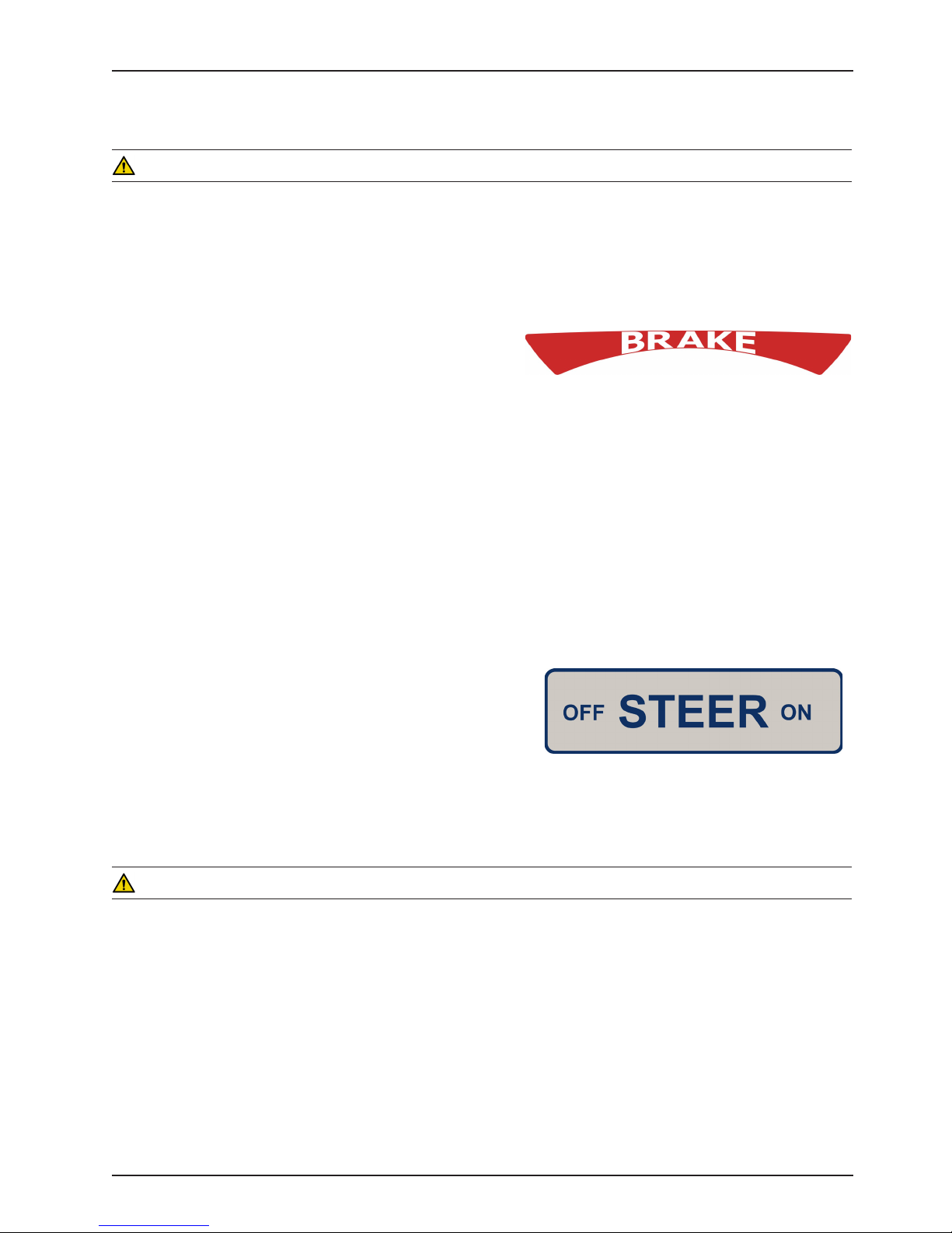
To activate the brakes, push down once on one of the pedals
located at the midpoint of the bed on both sides (identified by
the label at right). The pedal will remain in the lowered position,
indicating the brakes are engaged. To disengage the brakes,
push down once and the pedal will return to the upper position.
Note
The LED lights located on the outside of the head end siderails and on the foot end control panel will blink when the
brakes are not engaged only if the bed is plugged into a wall socket or is running on battery power (page 22 & page
30). The brakes will still operate properly when the bed is not plugged in.
STEER PEDAL OPERATION
When the bed is moved, the steer caster helps guide the bed along a straight line and helps the bed pivot around
corners.
To activate the steer caster, move the pedal located at the head
end of the bed to your right as shown on the label.
Note
For proper “tracking” of the steer caster, push the bed approximately 10 feet to allow the wheels to face the direction of
travel before engaging the steer pedal. If this is not done, proper “tracking” will not occur and the bed will be difficult
to steer.
WARNING
Do not attempt to move the foot end of the bed laterally when the steer pedal is activated. When the steer pedal is
activated, the steer caster at the foot end of the bed cannot swivel. Attempting to move the bed laterally when the
steer pedal is activated may cause injury to the user.
www.stryker.com 30 06 -109-101 REV A 17
Return To Table of Contents
Page 18
Litter Operation Guide
CPR EMERGENCY RELEASE
When quick access to the patient is needed, and the Fowler (head of bed) is raised, squeeze one of the two release
handles (marked by the red CPR label) and the fowler can quickly be guided down to a flat position.
Note
The handle can be released at any time to stop the Fowler from lowering.
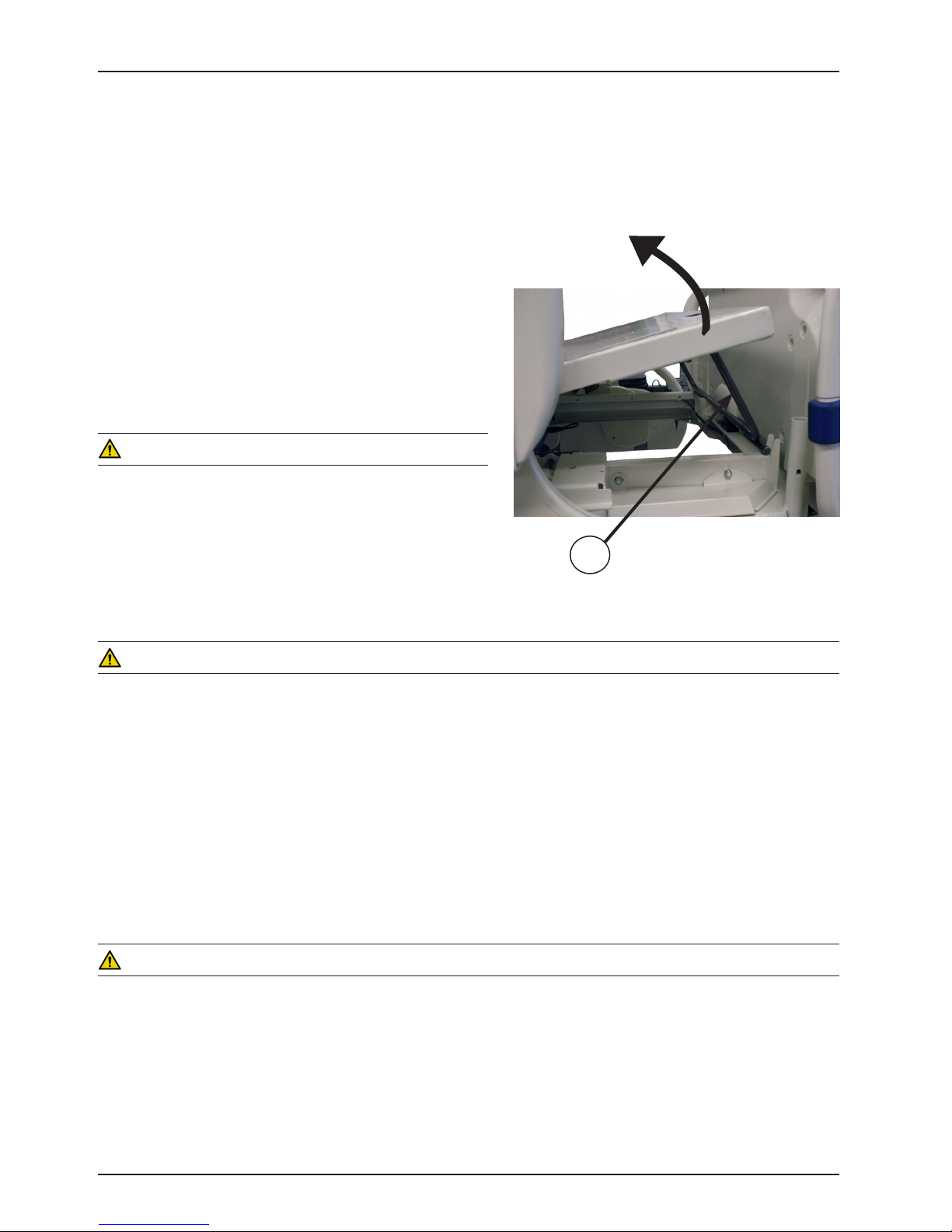
FOOT PROP USAGE
The foot prop causes the foot end of the Knee Gatch to rise
when the Gatch button is used to raise the Gatch. To lower
the foot end of the Gatch, release the prop by grasping the
end of the Knee Gatch, lifting upward and swinging the prop
(A) toward the head end of the bed which will disengage the
prop stop.
Head End
WARNING
To avoid injury while cleaning or servicing under the foot
section, secure the foot section with string or bungee cords or
hold it up out of the way.
Lift up Knee Gatch
Foot End
A
FRACTURE FRAME USAGE
A standard fracture frame can be mounted on the bed using the I.V. sockets located on all four corners of the bed. I.V.
poles can be used in conjunction with a fracture frame if the I.V. pole adaptor sockets are purchased.
WARNING
Use only retractable traction or fracture frames. Failure to use a retractable frame may result in injury to the patient
and/or damage to the equipment.
FOLEY BAG HOOKS USAGE
The standard foley bag hooks are found at four locations (on each side of the bed); below the seat (middle) section
and at the extreme foot end of the frame. Optional isolated foley bag hooks can be purchased and are located at the
foot end of the bed under the frame. The patient weight reading on the scale system is not affected when the optional
isolated foley bag hooks are used.
Patient Restraint Strap Locations
The bed has 10 locations for installing patient restraint straps on the litter top, five on each side of the bed.
WARNING
Improperly adjusted restraint straps can cause serious injury to a patient. The clinician must use her/his judgement
to determine proper use of restraint straps and restraint strap locations. Clean Velcro AFTER EACH USE. Saturate
Velcro with disinfectant and allow disinfectant to evaporate. (Appropriate disinfectant for nylon Velcro should be
determined by the hospital.)
Return To Table of Contents
18 300 6-10 9 -101 RE V A www.stryker.com
Page 19
Litter Operation Guide
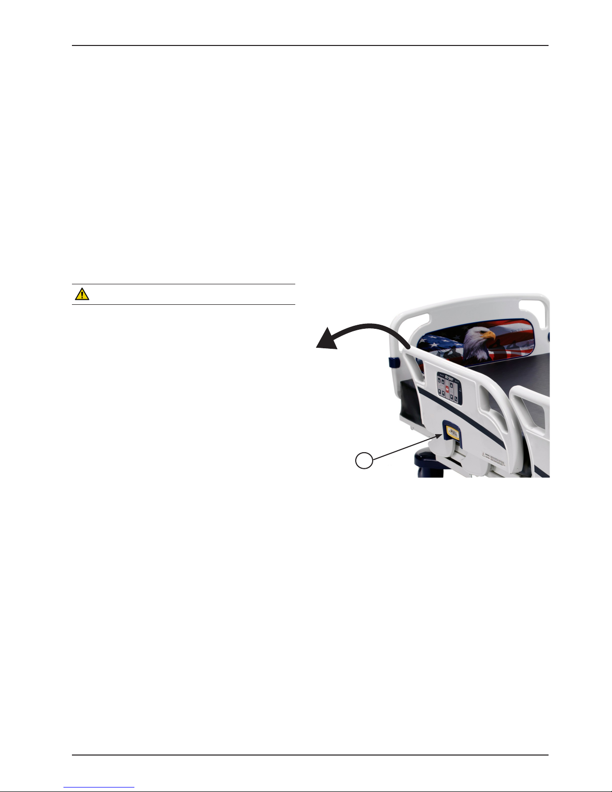
POSITIONING SIDERAILS
• The siderails can be locked at two heights (intermediate & full up).
• The siderails can slide in towards the bed when not in use. To remove the rail from the tucked position, grasp the
top of the rail and pull outward.
• To raise head end siderail to full height position, grasp the rail and swing it upward until it locks in place (two clicks
are heard).
Note: When the siderail is being raised, it does not lock in the intermediate position unless it is
brought back after the first click.
• To lower the siderail and lock in intermediate position, pull outward on the siderail release handle (A) and rotate
the siderail down toward the head end of the bed until it locks at the intermediate position.
• To lower the siderail in its full down position, pull outward on the release handle (A) and rotate the siderail
downward toward the head end of the bed until it is completely lowered.
• To raise and lower the foot end siderail, the same procedures are required as for the head end siderail, however,
the siderail swings toward the foot end of the bed.
WARNING
• Be sure the siderail is locked securely into position.
• Siderails in a full up or intermediate position are
not intended to keep patients from exiting the
bed. They are designed to keep a patient from
inadvertently rolling off the bed. Proper restraint
methods should be utilized to ensure the patient
remains in the bed.
• The intermediate position is only intended to assist
patients and users when getting in or out of the bed
in addition to assisting in positioning themselves in
the bed.
• The Intermediate position should not be used in
place of the full up position.
• The siderails are not intended to be used as a push
device.
A
To disengage the rail, pull outward on release handle (A) and swing the rail down to the desired height (intermediate
or full down). When storing siderails, ensure they are at a full down position.
CONTROL PANEL LIGHTS
The bed is equipped with lights to illuminate the head end siderail control panel and the red nurse call switches.
Both can be activated at the footboard control panel. Five settings are available for the control panel lights: Off, Low
Intensity, Medium Intensity, High Intensity and Nurse Call Only.
To change the control panel light settings, press the “Menu” button on the footboard. Scroll down through the menu
items and select “Backlight” then press “Enter”. Select the desired setting by highlighting it and then pressing “Enter”.
www.stryker.com 30 06 -109-101 REV A 19
Return To Table of Contents
Page 20
Litter Operation Guide
OPERATING I.V. POLES
WARNING
To avoid pinching your fingers, place the I.V. pole in the upright position
before using the drive handle.
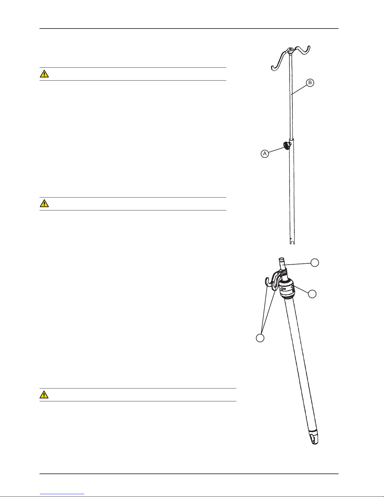
To use the “Removable” I.V. pole:
1. Install the pole at any of the four receptacles on the bed top (located
on all four corners of the frame).
2. To raise the height of the pole, turn knob (A) counterclockwise and
pull up on the telescoping portion (B) of the pole and raise it to the
desired height.
3. Turn knob (A) clockwise to tighten the telescoping portion in place.
CAUTION
The maximum safe working load for each I.V. pole is 40 pounds.
To use the 2-Stage Permanently Attached I.V. pole:
Note
The 2-stage permanently attached I.V. pole is an option and may have been
installed at either the head, foot or both ends of the bed. The choice was made
at the time the unit was purchased.
1. Lift and pivot the pole from the storage position and push down until it
rests in the receptacle.
2. To raise the height of the pole, pull up on the telescoping portion (A) until
it locks into place at its fully raised position.
3. Rotate the I.V. hangers (B) to desired position and hang I.V. bags.
4. To lower the I.V. pole turn the latch (C) clockwise until section (A) lowers.
A
C
B
CAUTION
The maximum safe working load for each I.V. pole is 40 pounds.
Return To Table of Contents
20 300 6-109 -101 REV A www.stryker.com
Page 21
Litter Operation Guide
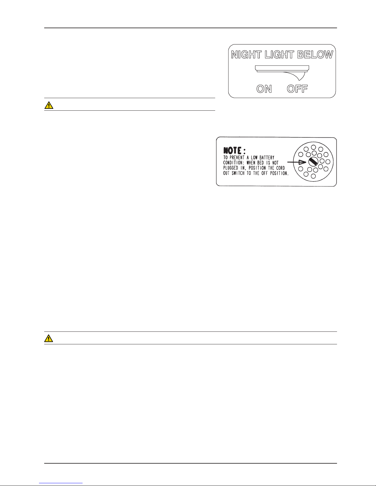
NIGHT LIGHT USAGE
The bed is equipped with two night lights to illuminate the floor area
around the bed. There is a switch under the litter thigh section on the
patient’s left side that turns both lights on and off.
WARNING
Service only by qualified personnel. Refer to the maintenance
manual. Verify the power cord is unplugged before servicing.
NURSE CALL BACKUP BATTERY (OPTIONAL)
• To prevent a low battery condition when the bed is not
plugged in, position the cord out switch at the head end
of the bed to the off position. The switch is identified by
the label shown below. If the switch is not positioned as
shown below and the bed power cord and pendant cord are
unplugged, the life of the backup battery will be significantly
reduced.
• If the Nurse Call battery needs to be replaced, a message will appear on the footboard display. The battery is
located on the patient’s left side at the head end of the bed. No tools are required to replace the battery. Unplug
the bed power cord from the wall socket and remove the battery from its housing to replace.
1/4” NURSE CALL PORT (OPTIONAL)
• The optional ¼” nurse call port is only designed to function with nurse call cords that have a ¼” TS connector.
• Fully insert the attached dummy plug into the port whenever a nurse call cord is not inserted into the port.
• If a continuous nurse call signal is observed, ensure that the dummy plug or a compatible nurse call cord is fully
inserted into the port.
USING THE 115 VOLT OUTLET (OPTIONAL)
• The 115V outlet has its own power cord that must be plugged into a properly grounded hospital grade three prong
wall receptacle different from the wall receptacle the bed power cord is plugged into.
• If the equipment plugged into the bed outlet is not receiving power, check the 10A circuit breakers located on the
litter frame under the head section. Reset, if necessary.
WARNING
• Only use equipment with the following electrical specs: 115VAC; 10A; 60Hz. Maximum total load drawn by
equipment used in this receptacle outlet must not exceed 10A. The total system chassis risk current should not
exceed 100 μA (microamps). Grounding continuity should be checked periodically.
• To avoid risk of electrical shock, unplug all power cords before opening the service compartment, junction box or
receptacle.
• Do not use the optional 115V outlet for life sustaining equipment.
CPR BOARD USAGE (OPTIONAL EQUIPMENT)
If the bed is equipped with the optional CPR board, it is stored on the bed’s headboard. To remove it, pull it away from
the headboard using both hands and lift it out of storage position.
www.stryker.com 30 06 -109-101 REV A 21
Return To Table of Contents
Page 22
Siderail Operation Guide
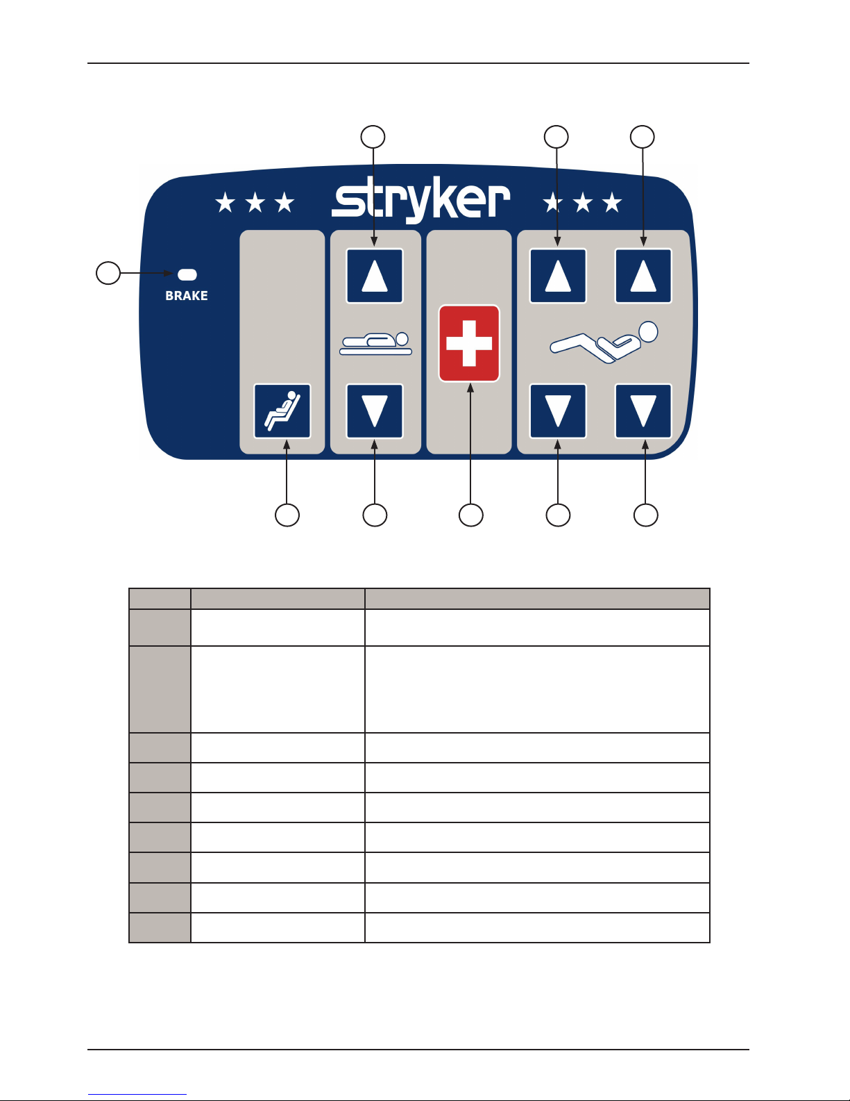
NURSE CONTROL FUNCTIONS (OUTSIDE SIDERAIL)
3
6
8
1
7
92 4 5
LEFT OUTER SIDERAIL SHOWN
(Right Outer Siderail same as the Left)
Button Button Name Button Function
Brake LED
1
Cardiac Chair
2
Bed/Litter Up Press to raise the Bed/Litter.
3
Bed/Litter Down Press to lower the Bed/Litter.
4
Nurse Call Push to activate Nurse Call.
5
Knee Gatch Up Press to raise the Knee Gatch.
6
Knee Gatch Down Press to lower the Knee Gatch.
7
Fowler Up Press to raise the Fowler.
8
Fowler Down Press to lower the Fowler.
9
LED flashes when Brakes are not engaged.
LED is “Off” when brakes are engaged.
Press to activate the Cardiac Chair function.
• The Knee will raise.
• The back will raise to approximately 60
• The bed will tilt to approximately −100 reverse
Trendelenburg (foot end down).
0
Note: The intent of the nurse call light on the siderails is to ensure the patient immediately knows which button to push
to contact the nurse station. Turning the light off may compromise this ability, especially in a darkened room.
Return To Table of Contents
22 300 6-109 -101 REV A www.stryker.com
Page 23
Siderail Operation Guide
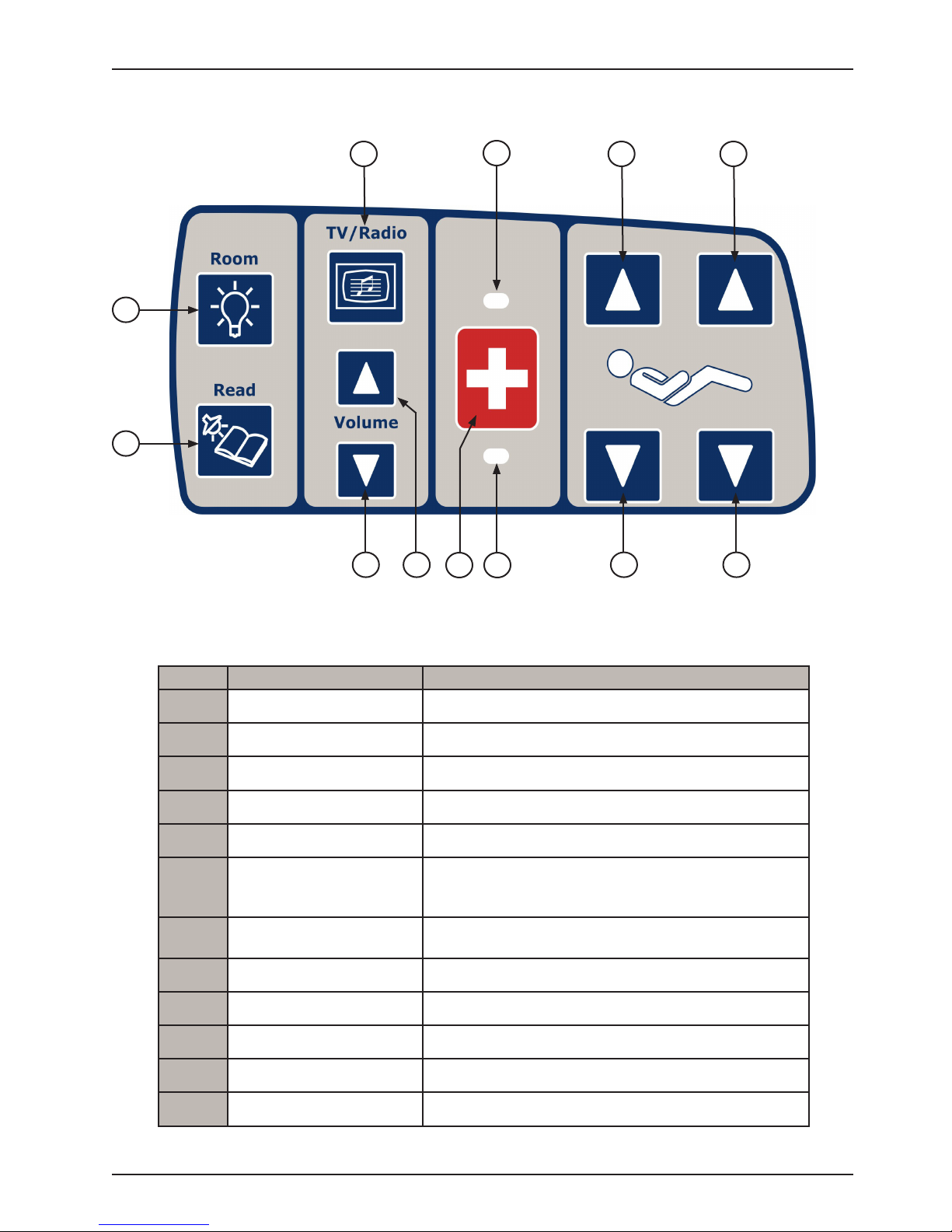
PATIENT CONTROL FUNCTIONS WITHOUT OPTIONAL SMART TV (INSIDE SIDERAIL)
1
8
9
12
2
3
5
6
7
LEFT INSIDE SIDERAIL SHOWN
(Right Inside Siderail same as the Left with exception of the Nurse Call and Nurse
Answer LED. LED 7 and 8 will change positions on the right inner siderail )
10
114
Button Button Name Button Function
TV / Radio Press to turn TV or radio on and to select a channel.
1
Room Light Press to turn the room light On/Off.
2
Bed Overhead Light Press to turn the bed overhead light On/Off.
3
TV/Radio Volume Down Press to decrease volume; TV or Radio.
4
TV/Radio Volume Up Press to increase volume; TV or Radio.
5
Press to activate Nurse Call.
10
11
12
Nurse Call
6
Nurse Call LED
7
Nurse Call Answer LED Illuminates green when answered by Nurse.
8
Fowler Up Press to raise the Fowler.
9
Fowler Down Press to lower the Fowler.
Knee Gatch Down Press to lower the Knee Gatch.
Knee Gatch Up Press to raise the Knee Gatch.
Note: Yellow LED will light when button is pushed.
Green LED will light with Nurse Station acknowledgment.
Illuminates amber when nurse call has been pressed by
patient.
www.stryker.com 30 06 -109-101 REV A 23
Return To Table of Contents
Page 24
Siderail Operation Guide
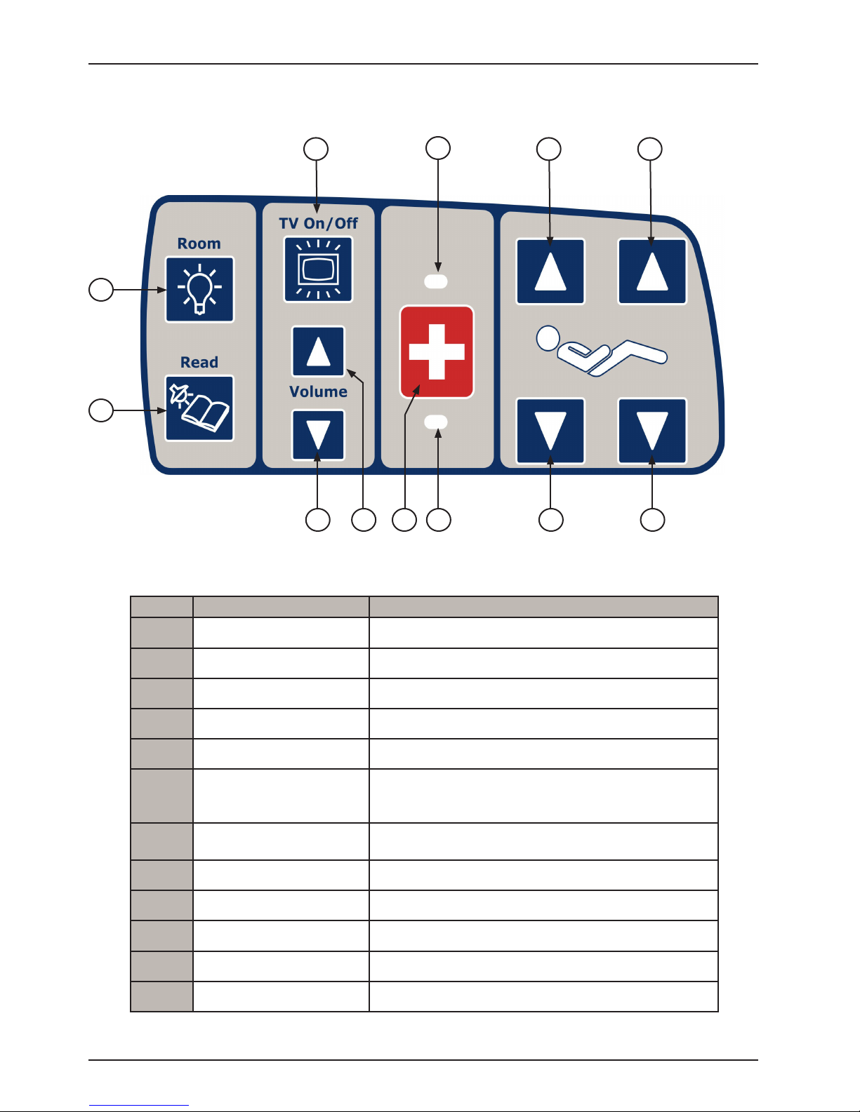
PATIENT CONTROL FUNCTIONS WITH OPTIONAL SMART TV (INSIDE SIDERAIL)
1
8
9
12
2
3
5 6
10
114 7
LEFT INSIDE SIDERAIL SHOWN
(Right Inside Siderail same as the Left)
Button Button Name Button Function
TV On/Off Press to turn TV on or off.
1
Room Light Press to turn the room light On/Off.
2
Bed Overhead Light Press to turn the bed overhead light On/Off.
3
TV/ Volume Down Press to decrease TV volume.
4
TV/ Volume Up Press to increase TV volume.
5
Press to activate Nurse Call.
10
11
Nurse Call
6
Nurse Call LED
7
Nurse Call Answer LED Illuminates green when answered by Nurse.
8
Fowler Up Press to raise the Fowler.
9
Fowler Down Press to lower the Fowler.
Knee Gatch Down Press to lower the Knee Gatch.
Note: Yellow LED will light when button is pushed.
Green LED will light with Nurse Station acknowledgment.
Illuminates amber when nurse call has been pressed by
patient.
12
Return To Table of Contents
24 3006-10 9-101 RE V A www.stryker.com
Knee Gatch Up Press to raise the Knee Gatch.
Page 25

Siderail Operation Guide
PATIENT TV CHANNEL CONTROL FUNCTIONS WITH OPTIONAL SMART TV (INSIDE SIDERAIL)
1
2
LEFT INSIDE SIDERAIL SHOWN
(Right Inside Siderail same as the Left)
Button Button Name Button Function
TV Channel Up Press to change TV channel up.
1
3
4
TV Channel Down Press to change TV channel down.
2
Mute TV
3
Closed Caption
4
www.stryker.com 30 06 -109-101 REV A 25
Press to mute TV volume.
Press again to turn the sound back on.
Press to display the closed captioning.
Press again to turn off the closed captioning.
Return To Table of Contents
Page 26

Footboard Operation Guide
INTENDED USE
The iBed® Awareness system is intended to serve as a secondary monitoring system, informing the operator via a
visual or audible alert when a preset condition changes.
• When the iBed® Awareness is turned “On”, the system has the ability to automatically monitor the following:
- Brake Set/Not Set
- Siderail Position
• Additionally, when the bed is in low height and/or Chaperone Bed Exit with Zone Control system is armed and/or
the Fowler 30+ is “On”, the system has the ability to monitor these features independently when iBed® Awareness
is turned “On”.
FOOTBOARD CONTROL PANEL BUTTONS
LOCKS
MOTION
BED EXIT
SCALE
iBED / MENU
2
1
4
8 101112
6
73 5 9 13
14
1715 16
181920
21
Button Name Button Name Button Name
Bed Motion Lock 9 Bed/Litter Down 18 Scale
1
Fowler 300+ 10 Fowler Up 19 Scale Zero
2
Patient Fowler Lock 11 Fowler Down 20 iBed On/Off
3
Patient Gatch Lock 12 Knee Gatch Up 21 Menu
4
22 24
2523
Patient Bed Up/
5
Down Lock
Trend 14 Cardiac Chair 23 Menu Down
6
Reverse Trend 15 CPR Drop 24 Exit
7
Bed/Litter Up 16 Bed Exit Arm/Disarm 25 Enter
8
Return To Table of Contents
26 300 6-109 -101 REV A www.stryker.com
13 Knee Gatch Down 22 Menu Up
17 Bed Exit Zone Control
Page 27

Footboard Operation Guide
FOOTBOARD CONTROL PANEL FUNCTIONS
2
8
10
126 14
1 4 73 5 9 11 13 15
Button Name Function
Locks all motion on bed. The Bed Motion Lock button will illuminate when
activated.
Moves bed out of trend and raises the Fowler to 300. The Fowler 300 + button and dashboard light will illuminate when activated. Note: The Fowler will
not go below 300 once the Fowler 300+ lock is activated. However, it may
be raised or lowered in the 300 to 600 range.
Locks out Fowler control at all locations (Siderail, Pendant, Head End) with
the exception of the operator controls located on the Footboard. The Patient
Fowler Lock button will illuminate when activated.
Locks out Gatch control at all locations (Siderail, Pendant, Head End).
The Patient Gatch Lock button will illuminate when activated. This function
also prevents the auto contour of the Gatch when motion is used. Note:
Auto contour is the feature of the bed that when fowler is actuated, Gatch
automatically moves with the Fowler.
Locks out Bed Height control at all locations (Siderail, Pendant, Head End)
with the exception of the operator controls located on the Footboard. The
Patient Bed Up/Down Lock button and Bed Motion dashboard light will
illuminate when activated.
Lowers foot end and raises head end of bed
When activated, the knee will raise, the Fowler will raise or lower to
approximately 600 degrees and the bed will tilt to approximately -100 Reverse
Trendelenburg (foot end down).
Activates electronic CPR function; flattens litter and puts bed in low
height.
LOCKS
MOTION
Bed Motion Lock
1
Fowler 300+
2
Patient Fowler Lock
3
Patient Gatch Lock
4
Patient Bed
5
Up/Down Lock
Trendelenburg Lowers head end and raises foot end of bed.
6
Reverse
7
Trendelenburg
Bed/Litter Up Raises Bed/Litter.
8
Bed/Litter Down Lowers Bed/Litter.
9
Fowler Up Raises Fowler.
10
Fowler Down Lowers Fowler.
11
Knee Gatch Up Raises Knee Gatch.
12
Knee Gatch Down Lowers Knee Gatch.
13
Cardiac Chair
14
CPR Drop
15
www.stryker.com 30 06 -109-101 REV A 27
Return To Table of Contents
Page 28

Footboard Operation Guide
FOOTBOARD CONTROL PANEL FUNCTIONS (CONTINUED)
Button Name Function
Bed Exit Arm/Disarm
16
Zone Control Changes the Zone.
BED EXIT
17
181920
1716
Activates Bed Exit system. The selected zone graphic will illuminate
when activated. When Bed Exit is in alarm mode, press and hold
“Arm/Disarm” to turn Bed Exit “Off”.
21
22 24
2523
SCALE
iBED/MENU
Scale Displays scale information on screen.
18
Zero Zeroes Bed.
19
On/Off Tu r ns iBed® Awareness system ON/OFF.
20
Menu Accesses MENU selections.
21
Menu Up Scroll Up through menu.
22
Menu Down Scroll Down through menu.
23
Exit
24
Enter Selects menu item; also used to Save operations.
25
Exits or Escapes from menu selection; also used to Cancel
operations.
Return To Table of Contents
28 300 6 -109 -101 R EV A ww w.stryker.com
Page 29

Footboard Operation Guide
LED INDICATORS: FOOTBOARD
The LED’s inform the operator of various product conditions as listed below.
H
B
F
G
A
DC E
LED Name: Function LED Color
Bed Motion Lock LED: LED is illuminated if Bed Motion is locked; blinking if
A
motion is attempted when lock is “On”.
Fowler 300+ Lock LED: LED is illuminated if Fowler 300+ is locked; blinking if
locked and Fowler motion is attempted while Fowler is at 300; flashes if lock
B
condition is violated by CPR.
Patient Control Fowler Lock LED: LED is illuminated if the Patient Fowler Lock
C
is “On”.
Patient Control Gatch Lock LED: LED is illuminated if the Patient Gatch Lock
D
is “On”.
Patient Control Bed Up/Down Lock LED: LED is illuminated if the Patient Bed
E
Up/Down Lock is “On”.
Zone 1 LED: LED is illuminated when Bed Exit is “On” and Zone 1 activated;
F
flashes if a Bed Exit event occurs.
Zone 2 LED: LED is illuminated when Bed Exit is “On” and Zone 2 activated;
G
flashes if a Bed Exit event occurs.
Zone 3 LED: LED is illuminated when Bed Exit is “On” and Zone 3 activated;
H
flashes if a Bed Exit event occurs.
AMBER
AMBER
AMBER
AMBER
AMBER
AMBER
AMBER
AMBER
www.stryker.com 30 06 -109-101 REV A 29
Return To Table of Contents
Page 30

Footboard Operation Guide
LED INDICATORS: FOOTBOARD (CONTINUED)
A
B
C
D
E F G
Optional
LED Name: Function LED Color
Bed Motion Lock LED: LED is illuminated when Bed Motion Lock is activated
or when the Patient Control (Fowler, Gatch, Bed Up/Down) Lock buttons are
A
activated.
Fowler 300+ LED: LED is illuminated when the Fowler 30+ is locked. The
LED will blink if the iBed® Awareness system is “On”, the Fowler 30+ is being
B
monitored and the Fowler goes below 30 degrees or the Fowler 30+ is turned
“O f f”.
Low Height LED: LED is illuminated when bed is in low height. The LED will
blink if the iBed® Awareness system is “On”, the low height is being monitored,
C
and the bed is not in low height.
Brake LED: LED is illuminated when the brake is set, and will blink if the brake
D
is not set.
Bed Exit LED (Optional): LED is illuminated when the Bed Exit is armed. The
LED will blink if the Bed Exit is turned Off while the iBed® Awareness system is
E
turned On or if Bed Exit alarms while monitored by iBed® Awareness system.
Bed Zero LED (Optional iBed® Awareness): LED is illuminated if Bed Zero is
F
successful.
Siderail LED (Optional iBed® Awareness): LED is illuminated if iBed®
G
Awareness system is “On”. The LED will blink when siderail state has changed.
Power LED: LED is illuminated when bed has power. GREEN
H
AMBER
AMBER
AMBER
AMBER
AMBER
AMBER
AMBER
H
Return To Table of Contents
30 30 06 -109-101 REV A www.stryker.com
Page 31

X
Footboard Operation Guide
DISPLAY SCREENS
There are 4 types of display screens listed by priority below with one being the highest.
Screen Ty p e Priority
Bed Exit Alarm Message
Alarm Indications
Brake Alarm Message
iBed® Awareness Alert Messages
Messages
Conditional Message
Menus Main Menu
Status Screen Default Screen
A. Power Up
• The initialization screen shown in Figure 1 will be displayed
on power up.
B. Status Screen (without iBed® Wireless option)
• Figure 2a shows an example of the default “Status” Screen.
• Information on this screen includes the ‘Fowler Angle’ and the
‘Trend Angle’ values.
• If this screen is inactive for 60 seconds, the Backlighting will
be reduced.
C. Status Screen (with iBed® Wireless option)
• Figure 2b shows an example of the default “Status” Screen.
• Information on this screen includes the WiFi and iBed Locator
connection status, ‘Fowler Angle’ and ‘Trend Angle’ values.
• If this screen is inactive for 60 seconds, the Backlighting will
be reduced.
23
1
2
3
4
5
6
Figure 1
0
-12
0
Icons
Wireless
Connectivity
Status
Signal
Strength Level
Signal
Strength, X
D. Message Screen
• As required message screens are provided during alarm conditions and user interaction with the bed.
E. Main Menu
• The Menu screen provides of list of available features accessible to the operator.
www.stryker.com 30 06 -109-101 REV A 31
Not
Connected;
Trying to
Connect
None Low Good Excellent
X < -90
dB or
X = 0 dB
-90 dB ≤
X < -71 dB
Connected
-71 dB ≤
X < -57 dB
X ≥ -57 dB
23
0
300.6lbs
Figure 2b
Figure 2a
-12
Return To Table of Contents
0
Page 32

Footboard Operation Guide
OPTIONAL CHAPERONE BED EXIT
“Bed Exit” LED
1. Before positioning the patient on the bed, the scale system must be zeroed for the Bed Exit System to function
properly (see page 35 for instructions on zeroing the scale system).
2. Position the patient on the bed and press the “Arm/Disarm” button to activate the Bed Exit function. The footboard
“Bed Exit” LED and dashboard “Bed Exit” LED will turn on.
3. To deactivate Bed Exit, press the “Arm/Disarm” button. The footboard “Bed Exit” LED and the dashboard “Bed
Exit” LED will turn off.
WARNING
The Bed Exit System is intended only to aid in the detection of a patient exiting the bed. It is NOT intended to replace
patient monitoring protocol. It signals when a patient is about to exit. Adding or subtracting objects from the bed after
arming the bed exit system may cause a reduction in the sensitivity of the bed exit system. To avoid possible injury
and to assure proper operation when using a powered mattress replacement system such as XPRT, do not initialize
(“Arm”) bed exit with Percussion, Vibration, Rotation or Turn Assist active. The patient motion and position resulting
from a dynamic therapy mattress may adversely affect bed exit system performance.
Return To Table of Contents
32 3006-10 9-101 RE V A www.stryker.com
Page 33

Footboard Operation Guide
CHAPERONE BED EXIT WITH ZONE CONTROL
“Zone 1” LED
1. Before positioning the patient on the bed, the scale system must be zeroed for the Bed Exit System to function
properly (see page 35 for instructions on zeroing the scale system).
2. Position the patient on the bed and press the “Arm/Disarm” button to activate the Bed Exit function. The footboard
“Zone 1” LED and dashboard “Bed Exit” LED will turn on.
3. The Bed Exit system with Zone Control automatically selects Zone 1. To change the Zone, press and hold the
“Zone” button until the light indicating the desired Zone comes on.
4. To deactivate Bed Exit, press the “Arm/Disarm” button. The selected footboard Zone light and the dashboard “Bed
Exit” lights will turn off.
WARNING
To avoid possible injury and to assure proper operation when using a powered mattress replacement system such as
XPRT, do not initialize (“arm”) bed exit with Percussion, Vibration, Rotation or Turn Assist active. The patient motion
and position resulting from a dynamic therapy mattress may adversely affect bed exit system performance.
Chaperone Zone Settings
The first zone (left indicator light) is the traditional Bed Exit zone. The patient can move around the bed freely but
cannot fully exit the bed or the alarm will sound.
The second zone (middle indicator light) is more restrictive than the first zone. When the zone is selected, the bed
measures the location of the patient’s center of gravity. If the patient’s center of gravity moves from the original
location more than 6.5 inches to either side or 13 inches toward the head or foot, an alarm will sound.
The third zone (right indicator light) is the most restrictive zone. When the zone is selected, the bed measures the
location of the patient’s center of gravity. If the patient’s center of gravity moves from the original location more than
1 inch to either side or 1 inch toward the head or foot, an alarm will sound.
NOTE
All zone dimensions are ± .5 inches.
www.stryker.com 30 06 -109-101 REV A 33
Return To Table of Contents
Page 34

Footboard Operation Guide
OPTIONAL SCALE SYSTEM
Weighing a Patient on the Scale System
The scale feature provides information to the caregiver on the weight of a patient.
To Weigh a Patient:
1. Press and hold the (“Scale”) button.
2. “Release Button” message flashes on the display as shown in figure 40.
3. Release the “Scale” button.
4. After the “Scale button has been released, “Weighing ... Do Not Touch
Bed” message will flash on the display as shown in Figure 41.
5. When weighing has been completed, the patient’s weight will be displayed
on the status screen as shown in Figure 42. The patient weight displayed is
stored in the system for later use.
NOTE
• Pressing the scale button again within 60 seconds of the first press (this
means that the scale data is still being displayed on the status screen), will
remove the data from the screen. This second button press will remove the
data so that the operator can walk away and not worry about having the data
available to non authorized persons. The second button press will not log a
value into the weight log. If the operator would like to have two consecutive
readings within 60 seconds, then the operator will need to press the button
once for the first weight reading, a second time will remove the weight information from the display and then a third time to take another weight reading
• If weight is displayed the “Scale” button can be pressed to turn off the scale.
Figure 40
Figure 41
Figure 42
CAUTION
Scale function may be affected by siderail/caster interference. With the litter fully lowered or lowered in Reverse
Trendelenburg, the siderails tucked under the litter in the storage position and the casters turned, there is the potential
for interference between the siderail and the caster. Raise the siderails when lowering the litter to the full down position
to prevent the interference from causing the scale system to weigh inaccurately.
WARNING
To avoid possible injury and to assure proper operation when using a powered mattress replacement system such as
XPRT:
• Confirm proper scale system operation following mattress installation. For best results, secure the mattress power
cord to prevent damage to the cord and interference with the bed frame and the scale system.
• Do not zero bed scales or weigh patient with Percussion, Vibration, Rotation or Turn Assist active. Patient motion
and position resulting from the dynamic therapy mattress may adversely affect scale system performance.
Return To Table of Contents
34 3006-10 9-101 RE V A www.stryker.com
Page 35

Footboard Operation Guide
OPTIONAL SCALE SYSTEM (CONTINUED)
Zeroing The Scale System
This feature provides the operator to zero the bed prior to weighing patient. Do not zero the bed while a patient is in
the bed. If this should occur, remove the patient and zero the bed again. If the Bed Exit is armed, you must disarm it
before the scale can be zeroed.
To Zero the Bed:
1. Press and hold the (“Zero”) button.
2. “Hold to Zero Bed” message will appear briefly on the display as shown in
figure 43.
3. Immediately following the “Hold to Zero Bed” message, the “Release
Button” message will flash on the display as shown in Figure 44.
4. Release the “Zero” button.
5. After the “Zero” button has been released, “Do Not Touch Bed” message
will flash on the display as shown in Figure 45.
6. When zeroing has been completed:
a. “Zeroing Successful” message will be shown on the display as shown
in Figure 46.
b. The Dashboard Bed Zero LED will illuminate.
c. The display will show the status screen with the scale information as
shown in Figure 47.
7. The bed is now ready for the patient.
Figure 43
Figure 44
Figure 45
Figure 46
Figure 47
Note
If there is a problem with a load cell or another component of the scale system, the system will try to zero up to 30
seconds, after which the scale monitor will read: “Unable to Zero - Try Again” if unsuccessful.
If the problem continues after three attempts, the scale system will lock and the scale monitor will read: “Unable to
Zer o”.
www.stryker.com 30 06 -109-101 REV A 35
Return To Table of Contents
Page 36

Footboard Operation Guide
MENU
• The Main Menu screen contains selectable product features to the caregiver. There are eight features listed in
the main menu as ordered below:
1. Weight Log (Weight Log is the Default Selection) 5. Scale Units (Change Scale Units)
2. Gain/Loss 6. Backlight (Backlighting)
3. Change Equip. (Change Equipment) 7. Advanced Options
4. Change Ptnt. Wgt. (Change Patient Weight) 8. Exit Menu
• To select a feature, press the “Menu Up” and “Menu Down” button to scroll to the desired feature. Highlight the
desired feature to select and then press the “Enter” button.
1. Weight Log
This feature provides the operator up to 10 of the last weights logged by the scale system as shown in Figure 3.
To display a list of the previous 10 weight readings:
• Press the “Menu” button and select the item “Weight Log”.
• Press the “Up” or “Down” buttons to scroll through the weight log.
• A weight reading is logged each time the scale button is pressed
and the bed is in the scale mode for at least 15 seconds.
• The first weight reading displayed (1.) is the most recent. If the
change in the patient’s weight since the last reading was taken
is less than .2 pounds, the log will not update. Zeroing the scale
system clears the weight log.
Figure 3
2. Gain/Loss
This feature provides information to the caregiver on the weight gain or
loss of the patient.
To e nable:
• Select “Gain/Loss” in the menu then press the “Enter” button, Figure
4 will be displayed.
• When “Release Button” message flashes on the display, release
the “Enter” button; “Do Not Touch Bed” message will flash on the
display.
• When Gain/Loss is On, “Gain/Loss Enabled” message displays.
NOTE: Refer to Figure 5
• The base represents the scale weight when the gain/loss feature
was enabled.
• The second piece of information represents the “Gain” or the “Loss”
and the weight difference between the current displayed weight and
the saved base weight.
NOTE: Refer to Figure 6
• If the Gain or the Loss exceeds 99.9 lb, then the system will display
‘---’ instead of a value.
Figure 4
Figure 5
Figure 6
Return To Table of Contents
36 30 06 -109-101 REV A www.stryker.com
Page 37

MENU (CONTINUED)
Hold to
Change Equipment
Equipment
Changed
Hold to Change
Patient Weight
3. Change Equipment
The change equipment feature allows the operator to add or remove item
from the product without affecting the patient weight.
To Change Equipment:
• Select “Change Equip.” in the menu then press the “Enter” button,
Figure 7 will be displayed or if the operator did not press the button
long enough the message “Hold Button Longer” will appear in the
message window.
• When “Release to Start” message displays on the screen, release
the “Enter” button; “Do Not Touch Bed” message will flash on
display.
• Figure 8 will display when the system is ready to change equipment.
• Press the “Enter” button to Add/Remove equipment or press the
“Exit” button to cancel operation.
• If “Enter” is pressed to Add/Remove Equipment then the
message “Do Not Touch Bed” will flash on the display.
• If “Exit” is pressed, “Operation Canceled” message will display.
• Figure 9 will be displayed when the system completes the change
equipment adjustment.
• The status screen will then display the weight of the patient only.
Footboard Operation Guide
Figure 7
Figure 8
4. Change Patient Weight
The change patient feature allows the operator to add or remove weight from the patient weight.
To C hange Patient Weight:
• Select “Change Pnt. Wgt.” in the menu.
• Press and hold the “Enter” button, Figure 10 will be displayed.
• When “Release Button” message displays on the screen, release
the “Enter” button; “Do Not Touch Bed” message will flash on
display.
• When the system is ready to change patient weight the following
information will be displayed:
- Allow user to Change patient Weight using arrow button;
- Display the new patient weight;
- Press” Enter” when done;
- Press “Exit” to cancel operation.
• If “Enter” is pressed, the message “Do Not Touch Bed” will flash on the display.
• If “Exit” is pressed, “Patient Weight Changed” message will display.
Figure 10
Figure 9
www.stryker.com 30 06 -109-101 REV A 37
Return To Table of Contents
Page 38

MENU (CONTINUED)
5. Scale Units
• The Change Scale Units feature allows the operator to select the
unit of value (lb or kg) for the scale information that is presented on
the display.
• When the change scale units is selected, Figure 11 is displayed.
• This screen will highlight the current scale unit setting.
• To change the scale unit setting, scroll to the desired setting and
press the “Enter” button.
• The default setting is “lb”
6. Backlight
• When the backlight feature is selected the display will change to the
backlight selection screen as shown in Figure 12.
• This screen will highlight the current backlight setting.
• Five settings are available for the backlight; Off, Low, Medium, High
and Nurse Call Only.
• To change the backlight setting; scroll to the desired setting and
press the “Enter” Button; “Save Successful” message will display.
• The default setting is “Low”.
Footboard Operation Guide
Fig ure 11
Figure 12
7. Advanced Options
The advanced menu items include:
1. Choose Exit Alarm
2. Brake Alarm
3. Awareness Alarm
4. Status To N/C
Advanced Options: Choose Exit Alarm
The caregiver can choose between 10 exit alarms.
To Select Alarm:
• Select “Choose Exit Alarm” from the menu.
• Scroll through the 10 Tone Patterns listed in the menu. A sample alarm will sound for each Tone Pattern
highlighted.
• Select desired Tone Pattern and Press “Enter”
• “Save Successful” message will be displayed.
Return To Table of Contents
38 30 06 -109-101 RE V A www.stryker.com
Page 39

MENU (CONTINUED)
Advanced Options: Brake Alarm
The caregiver can enable or disable an audible brake alarm feature. If enabled and the brakes are not
engaged when the bed is plugged in, an audible alarm will occur. This feature is only available on non-Zoom®
beds.
To Enable/Disable Brake Alarm:
• Select “Brake Alarm” from the menu.
• Use the Up and Down Arrow buttons to select enable or disable the alarm.
• Press “Enter” to save the alarm state.
• “Save Successful” message will be displayed.
Advanced Options: iBed® Awareness Alarm (Audible)
The caregiver can enable or disable an audible alarm for iBed® Awareness alert states.
To Enable/Disable Alarm:
• Select “Awareness Alarm” from the menu.
• Select “On” to Enable or “Off” to disable and then press “Enter”
• “Save Successful” message will be displayed.
Footboard Operation Guide
Advanced Options: Status Nurse Call ( iBed® Awareness Priority Signal)
The caregiver can enable or disable a priority signal alarm through the Nurse call system based on an iBed®
Awareness alarm state.
To Enable/Disable Alarm:
• Select “Status To N/C” from the menu.
• Select “On” to Enable or “Off” to disable and then press “Enter”
• “Save Successful” message will be displayed.
8. Exit Menu
Exits Main Menu screen and returns display to the default Status Screen.
www.stryker.com 30 06 -109-101 REV A 39
Return To Table of Contents
Page 40

Footboard Operation Guide
IBED® AWARENESS FUNCTIONALITY
• The iBed® Awareness provides functionality that will monitor status conditions on the product and produce an alert
if the state had changed.
• When the system is turned “On”, it monitors each of the siderail positions and brake automatically. If the bed is in
Low Height and/or the Bed Exit is armed and/or the Fowler 300+ lock is “On”, the system will also monitor these
features when iBed® Awareness is turned “On”. Note: If the Fowler 300+ lock is “On” before iBed® Awareness is
“On”, the system will also monitor the Fowler 300+ lock.
• In the event of a power loss, the iBed® Awareness system will store the last known condition and when power is
restored it will operate in this condition.
• iBed® Awareness will not be able to be turned “On” if any system error conditions exist that impede the function of
the iBed® Awareness system. The system errors that affect this feature include the four siderail sensors, the scale
system, the Fowler 300 + lock and the bed exit system. For details on error codes, refer to the Maintenance Manual.
IBED® AWARENESS LIGHT BAR AND SIDE LIGHTS
A light bar, located centrally on the front of the footboard, will illuminate and indicate the state of the iBed
Awareness system. Side lights located on the sides of the footboard will behave identical to the center light.
Features
• When the iBed® Awareness system is “On” the light bar turns green.
• If an alert state on the iBed® Awareness system is triggered, the light bar will change to the alert state and
flash AMBER.
• During an alert state, an AMBER dashboard LED associated with the alert will blink on the footboard and the
display screen will show the details of the alert state.
IBED® AWARENESS ON/OFF BUTTON
The On/Off control button is used to turn the iBed® Awareness system “On” and “Off”.
Features
When the button is pressed the iBed® Awareness system will save information based on the current state of the
product and based on the system rules will commence monitoring.
Turning on the iBed® Awareness system
1. Press the iBed On/Off button.
2. The following message will be displayed on the screen: “Awar eness On”.
Turning off the iBed® Awareness system
1. Press and hold the iBed On/Off button.
2. The following message will be displayed on the screen: “Awareness Off”.
Return To Table of Contents
40 30 06 -109-101 REV A www.stryker.com
Page 41

Footboard Operation Guide
IBED® AWARENESS MONITORING AND ALARMS
Low Height
• If the low height state changes:
1. The low height LED on the dashboard blinks and the display screen flashes between the message in
Figure 13 and the message in Figure 14.
Figure 13
Figure 14
Brakes
• If the brake state changes:
1. The brake LED on the dashboard blinks and the display screen flashes between the message in Figure
15 and the message in Figure 16.
Figure 15
Figure 16
Siderails
• If the siderail state changes:
1. The siderail LED on the dashboard blinks and the display screen flashes between the message in Figure
17 and the message in Figure 18.
Note
The arrow pointing to the siderail in Figure 17 and 18 will change depending on the siderail position in alarm.
www.stryker.com 30 06 -109-101 REV A 41
Figu re 17
Figure 18
Return To Table of Contents
Page 42

Footboard Operation Guide
IBED® AWARENESS MONITORING AND ALARMS (CONTINUED)
Bed Exit
• If the bed exit is disarmed:
1. The bed exit LED on the dashboard blinks and the display screen flashes between the message in Figure
19 and the message in Figure 20.
Figure 19
0
Fowler 30
• If the fowler 300+ lock state changes from a locked to an unlocked state:
1. The fowler 300+ lock LED on the dashboard blinks and the display screen flashes between the message
• If the fowler 300+ lock state changes to a lowered position:
1. The fowler 300+ lock LED on the dashboard blinks and the display screen flashes between the message
+ Lock
in Figure 21 and the message in Figure 22.
Figure 21
in Figure 23 message and the message in Figure 24.
Figure 20
Figure 22
Additional Alarm Conditions
• If an audible alarm is required, the caregiver can set the Awareness alarm to “On” through the Advanced
Options Menu in the Main Menu.
• If the caregiver would like to set the Awareness alarm to the Nurse Call Station, the “Status To N/C” must be
turned “On” through the Advanced Options Menu in the Main Menu.
Note
• By default these two advanced options are turned “Off”.
Return To Table of Contents
42 30 06-10 9-101 RE V A www.stryker.com
Figure 23
Figure 24
Page 43

Footboard Operation Guide
IBED® AWARENESS LOCKS
Fowler 300+ Lock Button
• The Fowler 300+ lock is a dual purpose button. It positions the Fowler to
300 and removes the bed out of trend.
• When the Fowler 300+ lock button is pressed, the bed will reposition if it
needs to and Figure 25 will be displayed.
• Once the bed reaches its final position, Figure 26 will be displayed.
• If the button is not held until the final position is reached Figure 27 will be
displayed.
• If bed is put in CPR position manually or by pressing the CPR button,
Figure 28 will be displayed.
• If the bed is at its final fowler 300+ position (Trend = 00, fowler = 300) and the user presses either the fowler
down or trend buttons, the display will toggle between figures 31 and 32.
Figure 25
Figure 26
Bed Motion Lock
• If Bed Motion lock button is
pressed, Figure 29 will be
displayed.
• If Bed Motion lock button is
pressed when already “on” then
Figure 30 will be displayed.
• If Motion is attempted when
lock is “On,” the display screen
flashes between Figure 31 and
32.
Note: The CPR Drop button overrides all locks.
Figure 27
Figure 29 Figure 30
Figure 31
Figure 28
Figure 32
Patient Control Locks
• If any of the Patient Control lock buttons are pressed, Figure 29 as shown above will be displayed.
• If any of the Patient Control lock buttons are pressed when already “on” then Figure 30 as shown above will
be displayed.
www.stryker.com 30 06 -109-101 REV A 43
Return To Table of Contents
Page 44

Optional Pendant Operation Guide
PENDANT - MOTION/NURSE CALL
(3006-315-011)
Press to activate Nurse Call.
Press to raise head section.
Press to lower head section.
PENDANT - MOTION/NURSE CALL/SMART TV (DIGITAL)
(3006-315-012)
Press to turn on/off the TV.
Press to increase the volume
of the TV.
Press to raise knee section.
Press to lower knee section.
Press to activate Nurse Call.
Press to change to a higher
numbered channel.
Press to decrease the volume
of the TV.
Press to raise head section.
Press to lower head section.
Press to turn on/off room lights
Return To Table of Contents
44 30 06 -109-101 REV A www.stryker.com
Press to change to a lower
numbered channel.
Press to raise knee section.
Press to lower knee section.
Press to turn on/off reading lights
Page 45

Optional Infrared (IR) Module
2
1
Item Name Function
IR (Infrared) Module Cable
1
IR (Infrared) Lens
2
iBed Locator Connection LED
3
Wireless (WiFi) Connection LED
4
Connects to the bed and provides power and signal
communications.
Provides infrared communications with the iBed
Locator.
Provides connection status for IR (infrared)
communications with iBed Locator.
Slow Flash - attempting to connect to iBed Locator.
Solid LED - iBed Locator connected.
Rapid Flash - Error condition detected.
OFF - iBed Locator is not trying to connect. This
occurs only on Zoom® and Battery Backup beds when
the brake is released.
Provides connection status for WiFi (wireless)
communications with wireless access point.
Slow Flash - WiFi attempting to connect.
Solid LED = WiFi connected.
Rapid Flash - WiFi was not connected after 6 minutes
and timed out.
3 4
www.stryker.com 30 06 -109-101 REV A 45
Return To Table of Contents
Page 46

Optional iBed Locator
The Optional iBed Locator component provides iBed Locator ID and battery status information to the IR Module.
Installation and operational procedures for the Optional iBed Locator are located in the iBed Locator Instructions For
Use manual (5212-00 9-101).
1
Item Name Function
IR (Infrared) Lens Provides Infrared communications with the iBed IR Module.
1
Return To Table of Contents
46 30 06 -109-101 REV A www.stryker.com
Page 47

Notes
www.stryker.com 30 06 -109-101 REV A 47
Return To Table of Contents
Page 48

Preventative Maintenance
Beds require an effective maintenance program, we recommend checking these items annually. Use this sheet for
your records. Keep on file.
CHECKLIST
____ _ All fasteners secure (reference all assembly drawings) .
__ ___ Engage brake pedal and push on the bed to ensure all casters lock securely.
__ ___ Inspect the brake assembly (Brake Ratchet Spring and Brake Bar) for degradation or signs of wear at the
foot end and head end of the bed. Ensure brake assembly components (locking caster and springs) are
functioning properly.
__ ___ “Brake” LED on the footboard and head end siderails blink when brakes are not engaged.
____ _ Locking steer caster engages and disengages properly.
__ ___ Siderails move, latch and stow properly.
__ ___ CPR release working properly.
__ ___ Foot prop intact and working properly.
__ ___ I.V. pole working properly.
__ ___ Foley bag hooks intact.
__ ___ Optional CPR board not cracked or damaged and stores properly.
__ ___ No cracks or splits in head and footboards.
__ ___ No rips or cracks in mattress cover.
__ ___ All functions on head end siderails working properly (including LED’s).
__ ___ All functions on footboard working properly (including LED’s).
__ ___ Scale and Bed Exit system calibrated properly.
__ ___ Motion Interrupt switches working properly.
__ ___ Night light working properly.
__ ___ Power cord and plug not frayed or damaged.
__ ___ No cables worn or pinched.
__ ___ All electrical connections tight.
__ ___ All grounds secure to the frame.
__ ___ Ground impedance not more than 100 mΩ (milliohms).
__ ___ Current leakage not more than 300 μA (microamps).
__ ___ Apply grease to the Litter grease points and fowler motor clutch (page 49).
__ ___ Ensure ground chains are clean, intact, and have at least two links touching the floor.
__ ___ Check Fowler angle for accuracy 00 - 600.
__ ___ Siderail switches working properly (iBed® Awareness option).
__ ___ Center Light Bar LED and side light LED working properly (iBed® Awareness option).
__ ___ Inspect footboard control labeling for signs of degradation.
__ ___ Inspect siderail gas spring for oil leaks and replace if necessary.
__ ___ Check fowler motor flexible mounting for damage or wear.
__ ___ Check all motion functionality.
____ _ Check Nurse Call functionality.
____ _ Check Nurse Call battery - optional equipment
__ ___ Check labels as specified in the Operations and Maintenance manuals for legibility, proper adherence and
integrity.
_____ Confirm iBed® Wireless Module and IR Module are intact and footboard icons are displaying
(iBed® Wireless Option)
Bed Serial Number:
Completed by: _______________________________________ Date: ___________________
Return To Table of Contents
48 30 06 -109 -101 REV A www.stryker.com
Page 49

GREASE POINTS
1. H/E Glide Rod
2. Ball Screw
3. Brake Spring
Preventative Maintenance
Siderail Assembly
1. Apply Syn-Tech NS-18191-G grease (p/n 3000-200-700) to Glide Rod surface.
Fowler Drive Assembly (Reference p/n: 3006-300-550)
(Reference p/n: 3006-400-105 (Head End) and 3006-400-300 (Foot End)
Glide Rod
Head End
shown
1. Apply Mobile #28 grease to entire length of ball screw.
2. If dry, apply a thin film layer of Syn-Tech grease (p/n 3000-200-700) to the outside of the brake spring.
Ball Screw
Brake Spring
Return To Table of Contents
www.stryker.com 30 06 -109-101 REV A 49
Page 50

Product Labels
Note: All product labels are standard on the bed unless otherwise noted as being optional.
Part Name/Number Product Label
Specification Label
3006-300-625
Shock Hazard
3006-002-708
Steer Lock
3006-090-013
Base Logo
3006-200-602
Caution/Danger Label
5212-100-807
ing
flammable anesthetics.
Explosion hazard. Do not use in the presence of
Return To Table of Contents
50 30 06 -109-101 REV A www.stryker.com
Page 51

Product Labels
Note: All product labels are standard on the bed unless otherwise noted as being optional.
Part Name/Number Product Label
Caution
3006-088-820
500 lb Max
3006-090-100
Cord Out Label
3006-090-028
Brake Pedal
3006-200-601
Foley Bag Hook
3006-300-601
www.stryker.com 30 06 -109-101 REV A 51
Return To Table of Contents
Page 52

Product Labels
Note: All product labels are standard on the bed unless otherwise noted as being optional.
Part Name/Number Product Label
Fowler Elevation Angle
3006-300-602
CPR Release
3006-300-603
Release Handle
3006-400-657
Warning
3006-400-656
Oxygen Warning
3006-508-010
Return To Table of Contents
52 300 6-109 -101 REV A www.stryker.com
Page 53

Product Labels
Note: All product labels are standard on the bed unless otherwise noted as being optional.
Part Name/Number Product Label
For hospital staff use only
3006-508-013
Stryker Logo
3006-508-014
Night Light
3006-310-601
Head End Inner Siderail
(Left)
3006-400-620
Head End Inner
Siderail (Right)
3006-400-610
www.stryker.com 30 06 -109-101 REV A 53
Return To Table of Contents
Page 54

Product Labels
Note: All product labels are standard on the bed unless otherwise noted as being optional.
Part Name/Number Product Label
Head End Inner Siderail
with NC
(Left)
3006-400-621
(Optional)
Head End Inner Siderail
with NC
(Right)
3006-400-611
(Optional)
Head End Inner Siderail
with Nurse Call and Lights
(Left)
3006-400-625
(Optional)
Head End Inner Siderail
with Nurse Call and Lights
(Right)
3006-400-615
(Optional)
Head End Inner Siderail
with Nurse Call, Lights
and TV-Radio
(Left)
3006-400-623
(Optional)
Return To Table of Contents
54 3006-10 9-101 RE V A www.stryker.com
Page 55

Product Labels
Note: All product labels are standard on the bed unless otherwise noted as being optional.
Part Name/Number Product Label
Head End Inner Siderail
with Nurse Call, Lights
and TV-Radio
(Right)
3006-400-613
(Optional)
Head End Inner Siderail
with Smart TV
(Left)
3006-430-131
(Optional)
Head End Inner Siderail
with Smart TV
(Right)
3006-430-132
(Optional)
Head End Outer Siderail
with Cardiac Chair
(Left)
3006-400-637
Head End Outer Siderail
with Cardiac Chair
(Right)
3006-400-647
www.stryker.com 30 06 -109-101 REV A 55
Return To Table of Contents
Page 56

Product Labels
Note: All product labels are standard on the bed unless otherwise noted as being optional.
Part Name/Number Product Label
Head End Outer Siderail
with Cardiac Chair
and Nurse Call
(Left)
3006-400-635
(Optional)
Head End Outer Siderail
with Cardiac Chair
and Nurse Call
(Right)
3006-400-645
(Optional)
Head End Outer Siderail
with Cardiac Chair
and Gatch/Fowler
(Left)
3006-400-634
(Optional)
Head End Outer Siderail
with Cardiac Chair
and Gatch/Fowler
(Right)
3006-400-644
(Optional)
Head End Outer Siderail
with Cardiac Chair, N/C
and Gatch/Fowler
(Left)
3006-400-633
(Optional)
Return To Table of Contents
56 30 06-10 9-101 RE V A www.stryker.com
Page 57

Product Labels
Note: All product labels are standard on the bed unless otherwise noted as being optional.
Part Name/Number Product Label
Head End Outer Siderail
with Cardiac Chair, N/C
and Gatch/Fowler
(Right)
3006-400-643
(Optional)
Footboard, without Scale
and without Bed Exit
3006-508-004
Footboard, with Bed Exit
3006-508-005
(Optional)
Footboard, with Bed Exit
and Scale
3006-508-007
(Optional)
Footboard, with Bed Exit
and Zone Control
3006-508-006
(Optional)
Footboard, with Bed Exit,
Scale and Zone Control
3006-508-009
(Optional)
Bed Exit
3006-50 8 -109
(Optional)
www.stryker.com 30 06 -109-101 REV A 57
Return To Table of Contents
Page 58

Product Labels
Note: All product labels are standard on the bed unless otherwise noted as being optional.
Part Name/Number Product Label
Bed Exit with Zone Control
3006-508-106
(Optional)
Scale System
3006-50 8 -107
(Optional)
Awareness Status
3006-508-108
(Optional)
Return To Table of Contents
58 30 06 -109-101 REV A www.stryker.com
Page 59

Product Labels
Note: All product labels are standard on the bed unless otherwise noted as being optional.
Part Name/Number Product Label
WiFi Capable
3006-50 8 -105
WiFi CPU Cover
3006-300-105
Wi-Fi
Capable
Wi-Fi
Capable
CPU P/N
3006-308-900
ONL Y
Base Stars Label
(3006-260-603)
United We Stand Label
(Left)
(3006-360-604)
United We Stand Label
(Right)
(3006-360-605)
Serving Those Who
Serve Label
(3006-560-031)
Return To Table of Contents
www.stryker.com 30 06 -109-101 REV A 59
Page 60

Cleaning
CAUTION
Unplug bed prior to cleaning or servicing unit.
Hand wash all surfaces of the bed with warm water and mild detergent. DRY THOROUGHLY. Do not steam clean
or hose off the S3™ MedSurg Bed, Model 3002 Patriot™ Series. Do not immerse any part of the bed. Some of the
internal parts of the bed are electric and may be damaged by exposure to water.
Suggested cleaners for bed surfaces:
• Quaternary Cleaners (active ingredient − ammonium chloride)
• Phenolic Cleaners (active ingredient − o−phenylphenol)
• Chlorinated Bleach Solution (5.25% − less than 1 part bleach to 100 parts water)
Avoid over saturation and ensure the product does not stay wet longer than the chemical manufacturer’s guidelines
for proper disinfecting.
CAUTION
SOME CLEANING PRODUCTS ARE CORROSIVE IN NATURE AND MAY CAUSE DAMAGE TO THE PRODUCT IF
USED IMPROPERLY. If the products described above are used to clean Stryker patient care equipment, measures
must be taken to insure the beds are wiped with a damp cloth soaked in clean water and thoroughly dried following
cleaning. Failure to properly rinse and dry the beds will leave a corrosive residue on the surface of the bed, possibly
causing premature corrosion of critical components. Failure to follow the above directions when using these types of
cleaners may void this product’s warranty.
For mattress cleaning instructions, please see the tag on the mattress, or contact the mattress manufacturer.
Clean Velcro AFTER EACH USE. Saturate Velcro with disinfectant and allow disinfectant to evaporate. (Appropriate
disinfectant for nylon Velcro should be determined by the hospital).
Return To Table of Contents
60 30 06 -109-101 REV A www.stryker.com
Page 61

Recycling Passport
Assembly Part number: 3006-343-895 (Reference Only)
A
B
Item Recycling/Material Code Important Information Qty
A (3006-308-900) CPU Board 1
B (0059-157-000) Power Supply 1
www.stryker.com 30 06 -109-101 REV A 61
Return To Table of Contents
Page 62

Recycling Passport
Assembly Part number: 3006-303-010 (Reference Only)
A
Item Recycling/Material Code Important Information Qty
A (3006-303-900) 37-Pin Plugover Board 1
Return To Table of Contents
62 3006-10 9-101 RE V A www.stryker.com
Page 63

Recycling Passport
Assembly Part number: 3006-400-125 (Reference Only)
A
Assembly Part number: 3006-400-225 (Reference Only)
B
Item Recycling/Material Code Important Information Qty
A (3006-400-910) Siderail Outer PCB, Left 1
B (3006-400-910) Siderail Outer PCB, Right 1
www.stryker.com 30 06 -109-101 REV A 63
Return To Table of Contents
Page 64

Recycling Passport
Assembly Part number: 3006-400-130 (Reference Only)
A
Assembly Part number: 3006-400-230 (Reference Only)
B
Item Recycling/Material Code Important Information Qty
A (3006-400-930) Siderail Outer PCB, Left 1
B (3006-400-930) Siderail Outer PCB, Right 1
Return To Table of Contents
64 30 06-10 9-101 RE V A www.stryker.com
Page 65

Recycling Passport
Assembly Part number: 3006-303-045 (Reference Only)
HEAD END, Patient Left Side
A
Item Recycling/Material Code Important Information Qty
A (3006-303-871) Battery 9V 1
www.stryker.com 30 06 -109-101 REV A 65
Return To Table of Contents
Page 66

Recycling Passport
Assembly Part number: 3001-314-012 (Reference Only)
A
Item Recycling/Material Code Important Information Qty
A (3001-314-920) Pendant Port PCB 1
Return To Table of Contents
66 30 06 -109-101 RE V A www.stryker.com
Page 67

Recycling Passport
Assembly Part number: 3006-501-011 (Reference Only)
A
Item Recycling/Material Code Important Information Qty
A (3006-501-900) Footboard PCB 1
www.stryker.com 30 06 -109-101 REV A 67
Return To Table of Contents
Page 68

Recycling Passport
Assembly Part number: 5212-300-053 (Reference Only)
A
Item Recycling/Material Code Important Information Qty
A (5212-300-930)
IR Module PCB Assembly
Return To Table of Contents
68 30 06 -109-101 REV A www.stryker.com
1
Page 69

Recycling Passport
Assembly Part number: 5212-300-012 (Reference Only)
A
Item Recycling/Material Code Important Information Qty
A (5212-300 -910)
Wireless Module PCB Assembly
www.stryker.com 30 06 -109-101 REV A 69
1
Return To Table of Contents
Page 70

EMC Information
S3™ MEDSURG BED, MODEL 3002 PATRIOT™ SERIES
Guidance and Manufacturer’s declaration - Electromagnetic Immunity
The S3™ MedSurg Bed, Model 3002 Patriot™ Series is suitable for use in the electromagnetic environment specified
below. The customer or the user of the S3™ MedSurg Bed, Model 3002 Patriot™ Series should assure that it is used
in such an environment.
Immunity Test IEC 60601 Test Level Compliance Level
Electrostatic Discharge (ESD)
IEC 61000-4-2
Electrostatic fast
Transient/burst
IEC 61000-4-4
Surge
IEC 61000-4-5
Voltage dips, voltage
variations and short
interruptions on power supply
input lines
IEC 61000-4-11
Power frequency (50/60 Hz)
magnetic field
IEC 61000-4-8
Note: UT is the a.c. mains voltage prior to applications of the test level.
+6 kV contact
+8 kV air
+2 kV for power
supply lines
+1 kV for input/
output lines
+8 kV differential mode
+2 kV common mode
<5%Ut (95% dipUt) for 0,5
cycle
40%Ut (60% dop in Ut) for
5 cycles
70%Ut (30% dip in Ut) for
25 cycles.
<5% Ut (>95% dip in Ut)
for 5 sec.
3 A/m 3 A/m Power frequency magnetic
+6 kV contact
+8 kV air
+2 kV for power
supply lines
+1 kV for input/
output lines
+8 kV differential mode
+2 kV common mode
<5%Ut (95% dipUt) for
0,5 cycle
40%Ut (60% dop in Ut)
for 5 cycles
70%Ut (30% dip in Ut)
for 25 cycles.
<5% Ut (>95% dip in Ut)
for 5 sec.
Electromagnetic
Environment Guidance
Floors should be wood,
concrete, or ceramic tile.
If floors are covered with
synthetic material, the relative
humidity should be at least
30%.
Main power quality should be
that of a typical commercial or
hospital environment.
Main power quality is that of
a typical commercial and/or
hospital environment.
Main power quality should be
that of a typical commercial
and/or hospital environment. If
the user of the S3™ MedSurg
Bed, Model 3002 Patriot™
Series requires continued
operation during power main
interruptions, it is recommended
that the device be powered
from an uninterrupted power
supply or a battery.
fields should be at levels
characteristic of a typical
location in a typical commercial
and/or hospital environment.
Return To Table of Contents
70 3 00 6 -109 -101 R EV A ww w.stryker.com
Page 71

EMC Information
S3™ MEDSURG BED, MODEL 3002 PATRIOT™ SERIES (CONTINUED)
Recommended separation distances between portable and mobile RF communications
equipment and the S3™ MedSurg Bed, Model 3002 Patriot™ Series.
The S3™ MedSurg Bed, Model 3002 Patriot™ Series is intended for use in an electromagnetic environment
in which radiated RF disturbances are controlled. The customer or the user of the S3™ MedSurg Bed,
Model 3002 Patriot™ Series can help prevent electromagnetic interferences by maintaining a minimum
distance between portable and mobile RF communications equipment (transmitters) and the S3™ MedSurg
Bed, Model 3002 Patriot™ Series as recommended below, according to the maximum output power of the
communications equipment.
Rated maximum output
power of transmitter
W
150 kHz to 80 MHz
0,01 1,12 0,12 0,23
0,1 0,38 0,38 0,73
Separation distance according to frequency of transmitter
m
80 MHz to 800 MHz
d=1,2
d=1,2
800 MHz to 2,5 GHz
d=2,3
1 1,2 1,2 2,3
10 3,8 3,8 7, 3
100 12 12 23
For transmitters rated at a maximum output power not listed above, the recommended separation distance d in meters
(m) can be estimated using the equation applicable to the frequency of the transmitter, where P is the maximum
output power rating of the transmitter in watts (W) according to the transmitter manufacturer.
Note 1
At 80 MHz and 800 MHz, the separation distance for the higher frequency range applies.
Note 2
These guidelines may not apply in all situations. Electromagnetic propagation is affected by absorption and reflection
from structures, objects and people.
www.stryker.com 30 06 -109-101 REV A 71
Return To Table of Contents
Page 72

EMC Information
S3™ MEDSURG BED, MODEL 3002 PATRIOT™ SERIES (CONTINUED)
The S3™ MedSurg Bed, Model 3002 Patriot™ Series is suited for use in the electromagnetic environment specified
below. The customer or the user of the S3™ MedSurg Bed, Model 3002 Patriot™ Series should assure that it is used
in such an environment.
Immunity Test IEC 60601 Test Level
Compliance
Level
Electromagnetic Environment - Guidance
Portable and mobile RF communications
equipment should be used no closer to any
part of the S3™ MedSurg Bed, Model 3002
Patriot™ Series, including cables, than the
recommended separation distance calculated
from the equation appropriate for the
frequency of the transmitter.
Recommended Separation Distance
Conducted
RF
IEC 61000-4-6
Radiated RF
IEC 61000-4-3
3 Vrms
150 kHz to 80 MHz
3 V/m
80 MHz to 2.5 GHz
3 Vrms
3 V/m
d=1,2
d=1,2
d=2,3
80 MHz to 800 MHz
where P is the maximum output power rating
of the transmitter in watts (W) according to
the transmitter manufacturer and d is the
recommended separation distance in meters
(m).
Field strengths from fixed RF transmitters,
as determined by an electromagnetic site
a
survey
level in each frequency range.
should be less than the compliance
b
Interference may occur in the vicinity of
equipment marked with the following symbol:
Note 1
At 80 MHz and 800 MHz, the higher frequency range applies.
Note 2
These guidelines may not apply in all situations. Electromagnetic propagation is affected by absorption and reflection
from structures, objects and people.
a
Field strengths from fixed transmitters, such as base stations for radio (cellular/cordless) telephones and land
mobile radios, amateur radio, AM and FM radio broadcast, and TV broadcast cannot be predicted theoretically with
accuracy. To assess the electromagnetic environment due to fixed RF transmitters, an electromagnetic site survey
should be considered. If the measured field strength in the location in which the S3™ MedSurg Bed, Model 3002
Patriot™ Series is used exceeds the applicable RF compliance level above, the S3™ MedSurg Bed, Model 3002
Patriot™ Series should be observed to verify normal operation. If abnormal performance is observed, additional
measures may be necessary, such as reorienting or relocating the S3™ MedSurg Bed, Model 3002 Patriot™ Series.
b
Over the frequency range 150 kHz to 80 MHz, field strengths are less than 3 V/m.
Return To Table of Contents
72 3 00 6 -109 -101 R EV A ww w.stryker.com
Page 73

EMC Information
S3™ MEDSURG BED, MODEL 3002 PATRIOT™ SERIES (CONTINUED)
Guidance and Manufacturer’s declaration - Electromagnetic Emissions
The S3™ MedSurg Bed, Model 3002 Patriot™ Series is intended for use in an electromagnetic environment
specified below. The customer or the user of the S3™ MedSurg Bed, Model 3002 Patriot™ Series should
assure that it is used in such an environment.
Emissions Test Compliance Electromagnetic Environment
Group 1,
RF Emissions
CI S P R 11
RF Emissions
CI S P R 11
without iBed®
Wireless option
Group 2,
with iBed®
Wireless option
Class A
The S3™ MedSurg Bed, Model 3002 uses RF energy
only for its internal function. Therefore, its RF emissions
are very low and are not likely to cause any interference
in nearby electronic equipment.
The S3™ MedSurg Bed, Model 3002 is suitable for use in
all establishments other than domestic and those directly
connected to the public low voltage power supply network
that supplies buildings used for domestic purposes.
Harmonic Emissions
IEC 61000-3-2
Voltage Fluctuations
Flicker Emissions
IEC 61000-3-3
Class A
Complies
www.stryker.com 30 06 -109-101 REV A 73
Return To Table of Contents
Page 74

Warranty
LIMITED WARRANTY
Stryker Medical Division, a division of Stryker Corporation, warrants to the original purchaser the S3™ MedSurg Bed,
Model 3002 Patriot™ Series to be free from defects in material and workmanship for a period of one (1) year after date
of delivery. Stryker’s obligation under this warranty is expressly limited to supplying replacement parts and labor for,
or replacing, at its option, any product which is, in the sole discretion of Stryker, found to be defective. If requested by
Stryker, products or parts for which a warranty claim is made shall be returned prepaid to the factory. Any improper
use or any alteration or repair by others in such manner as in Stryker’s judgment affects the product materially and
adversely shall void this warranty. Any repair of Stryker products using parts not provided or authorized by Stryker shall
void this warranty. No employee or representative of Stryker is authorized to change this warranty in any way.
Stryker Medical beds are designed for a 15 year expected service life under normal use, conditions, and with
appropriate periodic maintenance as described in the maintenance manual for each device. Stryker warrants to the
original purchaser that the welds on its beds will be free from structural defects for the expected 15 year life of the bed
as long as the original purchaser owns the product.
Stryker Medical optional components and/or accessories are warranted as follows:
• Motion/Nurse Call Pendant: Two (2) years service life under normal use and proper care
• Motion/Nurse Call/SmartTV Pendant: Two (2) years service life under normal use and proper care
• iBed Wireless Components: Ten (10) years service life under normal use and proper care
This statement constitutes Stryker’s entire warranty with respect to the aforesaid equipment. Stryker Makes No Other
Warranty Or Representation, Either Expressed Or Implied, Except As Set Forth Herein. There Is No Warranty Of
Merchantability And There Are No Warranties Of Fitness For Any Particular Purpose. In No Event Shall Stryker Be
Liable Here Under For Incidental Or Consequential Damages Arising From Or In Any Manner Related To Sales Or
Use Of Any Such Equipment.
TO OBTAIN PARTS AND SERVICE
Stryker products are supported by a nationwide network of dedicated Stryker Field Service Representatives. These
representatives are factory trained, available locally, and carry a substantial spare parts inventory to minimize repair
time. Simply call your local representative, or call Stryker Customer Service USA at 1-800-327−0770, Canada
1-888-233-6888.
SERVICE CONTRACT COVERAGE
Stryker has developed a comprehensive program of service contract options designed to keep your equipment operating
at peak performance at the same time it eliminates unexpected costs. We recommend that these programs be activated
before the expiration of the new product warranty to eliminate the potential of additional equipment upgrade charges.
A SERVICE CONTRACT HELPS TO:
• Ensure equipment reliability
• Stabilize maintenance budgets
• Diminish downtime
• Establish documentation for JCAHO
• Increase product life
• Enhance trade-in value
• Address risk management and safety
Return To Table of Contents
74 3006-10 9-101 RE V A www.stryker.com
Page 75

Warranty
SERVICE CONTRACT PROGRAMS
Stryker Offers the following service contract programs:
Service Agreement Options * Premium Complete Standard
Annually scheduled preventative maintenance X X
All parts X X
All labor and travel X X
Unlimited emergency service calls X X
Priority one contact: two hour phone response X X
Most repairs completed within 3 days X X
JCAHO documentation X X X
On−site record of PM & emergency service X X
Factory−trained Stryker service technician X X X
Stryker authorized parts used X X X
Service during regular business hours (8−5) X X X
* Does not include maintenance due to abuse or for any disposable items. Stryker reserves the right to change options without notice.
Stryker Medical also Offers personalized service contracts.
Pricing is determined by age, location, model and condition of product.
For more information on our service contracts,
please call your local representative.
RETURN AUTHORIZATION
Merchandise cannot be returned without approval from the Stryker Customer Service Department. An authorization
number will be provided which must be printed on the returned merchandise. Stryker reserves the right to charge shipping and restocking fees on returned items. Special, Modified, Or Discontinued Items Not Subject To Return.
DAMAGED MERCHANDISE
ICC Regulations require that claims for damaged merchandise must be made with the carrier within fifteen (15) days of
receipt of merchandise. Do Not Accept Damaged Shipments Unless Such Damage Is Noted On The Delivery Receipt
At The Time Of Receipt. Upon prompt notification, Stryker will file a freight claim with the appropriate carrier for damages incurred. Claim will be limited in amount to the actual replacement cost. In the event that this information is not
received by Stryker within the fifteen (15) day period following the delivery of the merchandise, or the damage was not
noted on the delivery receipt at the time of receipt, the customer will be responsible for payment of the original invoice
in full. Claims for any short shipment must be made within thirty (30) days of invoice.
INTERNATIONAL WARRANTY CLAUSE
This warranty reflects U.S. domestic policy. Warranty outside the U.S. may vary by country. Please contact your local
Stryker Medical representative for additional information.
www.stryker.com 30 06 -109-101 REV A 75
Return To Table of Contents
Page 76

Page 77

Page 78

UNITED STATES
Stryker Medical
3800 E. Centre Ave.,
Portage, Michigan USA
49002
EC REP
European Representative
Stryker France
ZAC Satolas Green Pusignan
Av. De Satolas Green
69881 MEYZIEU Cedex
France
2011/03 3006-10 9 -101 REV A www.stryker.com
 Loading...