

Page 1

InTouch® Critical Care Bed
REF
FL27 (2131/2141)
Version 4.0 with Wi-Fi /
Isolibrium™ (2971) support surface
Maintenance Manual
2018/03 H.0 2141-209-002 REV H www.stryker.com
Page 2

Page 3
General warning
~
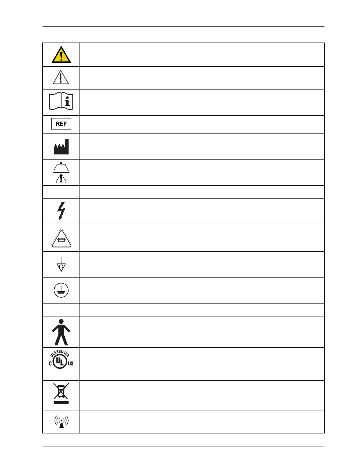
1.6 SYMBOLS
Caution
Consult instructions for use
Catalogue number
Manufacturer
Safe Working Load Symbol
Symbols
10A 250V
IPX4
87VL
Alternating Current
Dangerous Voltage Symbol
Fuse Rating for Beds with the 100V~ or 120V~ Electric System
Potential Equalization
Protective Earth Terminal
Protection from liquid splash
Type B Applied Part
Medical Equipment Classified by Underwriters Laboratories Inc. With Respect to Electric Shock, Fire,
and Mechanical Hazards Only in Accordance with ANSI/AAMI ES60601-1: 2005 and CAN/CSA-C22.2
No. 60601-1:08.
In accordance with European Directive 2012/19/EU on Waste Electrical and Electronic Equipment,
this symbol indicates that the product must not be disposed of as unsorted municipal waste, but
should be collected separately. Refer to your local distributor for return and/or collection systems
available in your country.
www.stryker.com 2141-209-0 02 RE V H 3
Non-ionizing radiation; i.e. RF transmitter (Wi-Fi)
Return To Table of Contents
Page 4
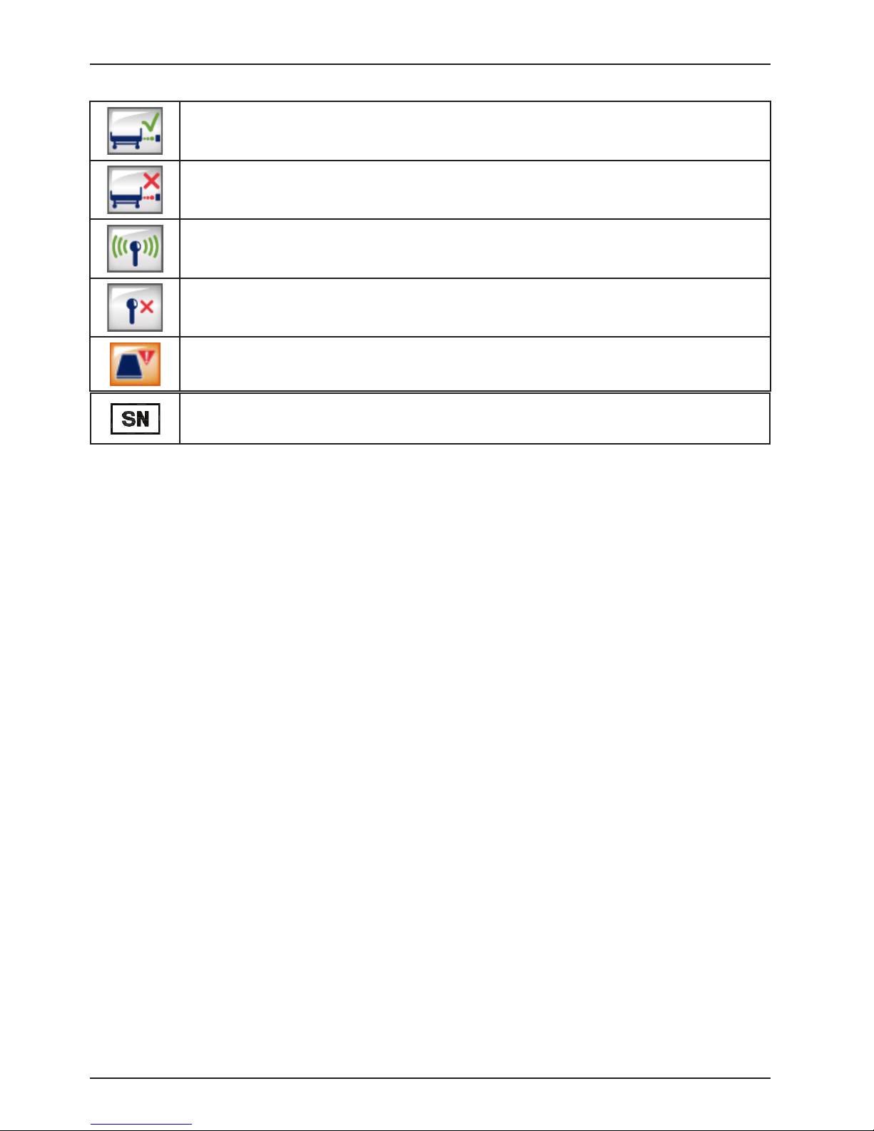
iBed Locator is connected
iBed Locator is not connected
Wireless Network is connected
Wireless Network is not connected
Support surface call maintenance
Serial number
Symbols
Return To Table of Contents
4 2141-2 09 -002 REV H www.stryker.com
Page 5

Table of Contents
Symbols ................................................................................3
Warning / Caution / Note Definition ............................................................9
Introduction ............................................................................10
Product Description ...................................................................10
Intended Use: InTouch Critical Care Bed ....................................................10
Intended Use – iBed® Wireless with iBed Awareness ..........................................11
Expected service life ..................................................................11
Contraindications.....................................................................11
Specifications .......................................................................12
Environmental Conditions...............................................................14
Product Illustration....................................................................15
Contact Information ...................................................................16
Serial Number Location ................................................................16
Specification Label Location ............................................................16
Summary of Safety Precautions .............................................................17
Static Discharge Precautions ...............................................................21
Protecting against Electrostatic Discharge (ESD) .............................................21
Setup .................................................................................22
Installation .............................................................................23
Installing the XPRT Therapy support surface (optional) .........................................23
Installing the PositionPRO support surface (optional) ..........................................23
Installing the Isolibrium support surface (optional).............................................23
Installing iBed Wireless (120V North American only) (optional) ...................................23
Maintenance Menu Guide ..................................................................24
InTouch Configuration Screen............................................................25
A. Bed Calibration .................................................................25
B. Full Diagnostic .................................................................36
C. Touch Screen Calibration .........................................................37
D. Optional Wi-Fi Configuration .......................................................38
E. Bed Options Configuration.........................................................39
F. Serial Number Configuration .......................................................40
Accessing the Isolibrium diagnostic menu...................................................41
Reviewing active Isolibrium errors .........................................................42
Reviewing and Clearing Isolibrium Error History...............................................42
Viewing Advanced Signal Values for Isolibrium ...............................................43
Running a Diagnostic Test for Isolibrium ....................................................44
Cleaning...............................................................................46
Cleaning a support surface .............................................................46
Preventive Maintenance ...................................................................47
Quick Reference Replacement Parts..........................................................49
Troubleshooting .........................................................................51
Bed Troubleshooting ..................................................................51
Scale Troubleshooting .................................................................57
Error Codes ............................................................................58
Error Handling .......................................................................58
Error Messages ......................................................................58
www.stryker.com 2141-209-0 02 RE V H 5
Page 6

Table of Contents
CPU/Power Board - QDF75-0440 ............................................................63
Fuse Specification ....................................................................64
Bed Electrical Diagram ....................................................................65
Service Information.......................................................................84
Bed lift Actuator (Head) Removal and Replacement - (Base).....................................84
Bed lift Actuator (Foot) Removal and Replacement - (Base) .....................................85
Fowler Actuator Removal and Replacement - (Litter) ..........................................86
Gatch Actuator Removal and Replacement - (Litter) ...........................................87
Foot Actuator Removal and Replacement - (Litter) ............................................88
Zoom® Drive Actuator Removal and Replacement (2141 Model Only) - (Base) .......................89
CPU / Power Board Removal and Replacement - (Litter)........................................90
Load Cell (Head End) Removal and Replacement - (Litter)......................................91
Load Cell (Foot End) Removal and Replacement - (Litter) ......................................92
Display Removal and Replacement - (Footboard) .............................................93
Brake Control Board Removal and Replacement - (Footboard) ...................................94
Function Selection/LED Board Removal and Replacement - (Footboard) ...........................95
Touch Screen Removal and Replacement - (Footboard) ........................................96
Battery Removal and Replacement - (Footboard) .............................................97
Brake / Neutral / Drive Potentiometer Removal and Replacement - QDF27-2024 ......................98
Battery Removal and Replacement - (Litter) .................................................99
Fowler Angle Sensor Removal and Replacement - (Litter) .....................................10 0
Gatch Angle Sensor Removal and Replacement - (Litter) ......................................101
Foot Angle Sensor Removal and Replacement - (Litter) .......................................10 2
Base Angle Sensor Removal and Replacement - (Base) .......................................103
Trend Angle Sensor Removal and Replacement - (Litter) ......................................104
Headwall Communication Board Removal and Replacement - (Litter) .............................105
IR Module Removal and Replacement - (Litter) (Optional) ......................................106
Wi-Fi Board Removal and Replacement - (Footboard) (Optional) .................................107
Base Assembly, Hood....................................................................109
Base Assembly, Brake ...................................................................111
Base Assembly, Caster Lock (Model 2131 Only) ................................................114
Base Assembly, Caster Non-Lock (Model 2141 Only).............................................1 15
Angle Sensor Assembly ..................................................................116
Base Assembly, Electrical ................................................................. 1 17
Base Assembly, Zoom® ..................................................................12 3
Base Assembly, Zoom® Drive (Model 2141 Only) ................................................12 5
Bed Labeling ..........................................................................12 7
Lift Assembly ..........................................................................131
Spring Assembly........................................................................13 5
Litter Assembly......................................................................... 13 6
Litter Assembly, Interior Frame .............................................................140
Litter Assembly with Serial Port.............................................................14 3
Litter Assembly, Upper Frame .............................................................14 4
Litter Assembly, Foot End .................................................................146
6 2141-2 09 -002 REV H www.stryker.com
Page 7

Table of Contents
Assembly Drawings (Continued)
Litter Assembly, Standard Cabling...........................................................150
Litter Assembly, Electrical................................................................. 15 1
120V Electric System ....................................................................157
Coiled Power Cord ......................................................................15 8
Litter Assembly, Foot End, with Mattress Connector..............................................15 9
Standard Outlet ........................................................................160
Litter Assembly, Optional Dual 120V Outlet . . . . . . . . . . . . . . . . . . . . . . . . . . . . . . . . . . . . . . . . . . . . . . . . . . . . 161
CPR Assembly, Mechanical ...............................................................163
Handle Assembly (Model 2131 Only) .........................................................168
Zoom® Handle Assembly (Model 2141 Only) ...................................................169
Zoom® Assembly........................................................................ 171
Optional No Head End Control Panel......................................................... 17 2
Optional Head End Control Panel Assembly ................................................... 17 3
Siderail Mounting Assembly, Head End ....................................................... 17 5
Standard Siderail Assembly, Head End, Right ..................................................17 6
Standard Siderail Assembly, Head End, Left ...................................................18 0
Standard Siderail Assembly, Labeling ........................................................18 4
Optional Siderail Assembly, Head End, with Speaker/iAudio ........................................18 5
Optional Siderail Assembly, Head End, with Speaker/with NC/with iAudio ..............................18 6
Optional Siderail Assembly, Head End, with Speaker/iAudio/IR ......................................18 8
Optional Siderail Assembly, Head End, with Speaker/with NC/with iAudio/with iBed® Wireless...............18 9
Siderail Mounting Assembly, Foot End........................................................193
Standard Siderail Assembly, Foot End, Right ...................................................194
Standard Siderail Assembly, Foot End, Left ....................................................197
Standard Siderail Assembly without iBed......................................................200
Optional Siderail Assembly with iBed ........................................................201
Headboard and Footboard Assembly .........................................................202
Standard Footboard Assembly .............................................................203
Footboard Assembly without iBed ...........................................................205
Footboard Assembly with iBed .............................................................208
Footboard Assembly with iBed and Wi-Fi......................................................211
Bed Extender - FA64234-XXX .............................................................. 214
Bed Extender Pad with Position Pro Mattress - DM64196-XXX ...................................... 2 15
Bed Extender Pad with XPRT™ Mattress - DM64197-XXX .........................................215
Line Management Clip - FA64210-XXX .......................................................216
IV Pole Assembly, Permanent - FA64221-XXX/FA64238-XXX ....................................... 217
IV Pole Ass’y, Dual Head End, Permanent - FA64202-XXX .........................................218
Monitor Tray Assembly - FA64214-XXX .......................................................220
Upright Oxygen Bottle Holder Assembly - FA64187-XXX...........................................221
Right-Fit Oxygen Bottle Holder Assembly - FA64203 .............................................222
Pendant Assembly with Motion Control - FA64228-XXX ..........................................223
Pendant Assembly with Motion Control/NC - FA64226 ...........................................224
Pendant Assembly with Motion Control/Smart TV - FA64227.......................................225
Pendant Assembly with Motion Control/NC/Smart TV - FA64225....................................226
www.stryker.com 2141-209-0 02 RE V H 7
Page 8

Table of Contents
Pendant Clip Assembly - FA64186-XXX ......................................................226
Roller Bumpers.........................................................................227
Traction Sleeve Assembly, 4 in. x 1/2 in. - FA64215-XXX ..........................................228
Traction Sleeve Assembly, 4 in. x 3/4 in. - FA64216-XXX ..........................................229
Traction Sleeve Assembly, 8 in. x 1/2 in. - FA64217-XXX ..........................................230
Traction Sleeve Assembly, 8 in. x 3/4 in. - FA64218-XXX ..........................................231
Traction Sleeve Assembly, 6-1/2 in. x 3/4 in. - FA64219-XXX .......................................232
Wall Saver Cable Assembly - FA64208 . . . . . . . . . . . . . . . . . . . . . . . . . . . . . . . . . . . . . . . . . . . . . . . . . . . . . . . 233
X-ray Cassette Holder Assembly - FA64205-XXX................................................234
Tube Support ..........................................................................236
Recycling Passports .....................................................................237
Warranty .............................................................................249
Limited Warranty ....................................................................249
Warranty exclusion and damage limitations.................................................249
To Obtain Parts and Service ...........................................................249
Return Authorization..................................................................249
Damaged Merchandise ...............................................................249
International Warranty Clause...........................................................249
8 2141-2 09 -002 REV H www.stryker.com
Page 9

Warning / Caution / Note Definition
The words WARNING, CAUTION, and NOTE carry special meanings and should be carefully reviewed.
WARNING
Alerts the reader about a situation, which if not avoided, could result in death or serious injury. It may also describe
potential serious adverse reactions and safety hazards.
CAUTION
Alerts the reader of a potentially hazardous situation, which if not avoided, may result in minor or moderate injury to the
user or patient or damage to the equipment or other property. This includes special care necessary for the safe and
effective use of the device and the care necessary to avoid damage to a device that may occur as a result of use or
misuse.
Note
This provides special information to make maintenance easier or important instructions clearer.
www.stryker.com 2141-209-0 02 RE V H 9
Return To Table of Contents
Page 10

Introduction
This manual assists you with the operation or maintenance of the Stryker Model FL27 (2131/2141) InTouch® Critical
Care bed. Read this manual thoroughly before operating or maintaining this product. Set methods and procedures to
educate and train your staff on the safe operation or maintenance of this product.
WARNING
• Improper usage of the product can cause injury to the patient or operator. Operate the product only as described
in this manual.
• Do not modify the product or any components of the product. Modifying the product can cause unpredictable
operation resulting in injury to patient or operator. Modifying the product also voids its warranty.
Notes
• This manual is a permanent part of the product and should remain with the product even if the product is sold.
• Stryker continually seeks advancements in product design and quality. This manual contains the most current
product information available at the time of printing. There may be minor discrepancies between your product and
this manual. If you have any questions, contact Stryker Customer Service or Technical Support at 1–800–327-0770.
PRODUCT DESCRIPTION
InTouch is an AC-powered, adjustable hospital bed designed to position human patients for procedures, therapy, and
recovery in a healthcare environment, and transport patients between bays and procedural rooms. InTo u c h measures
and displays patient weight. The scale output is not intended to be used to determine diagnosis or treatment. The nurse
call allows patients to alert an operator when the patient requires assistance. There is a 30-degree head of bed (HOB)
button that puts the patient at a 30-degree angle that is calculated relative to the base to assist in ventilator-associated
pneumonia (VAP) prevention. When the Chaperone bed exit system is active, it monitors a chosen zone, and alerts the
operator of a deliberate or non-deliberate bed exit. The bed has 39 prerecorded clinical phrases in 24 languages and
a sound feature that offers various environmental and musical selections.
INTENDED USE: INTOUCH CRITICAL CARE BED
InTouch is intended for use by patients in an acute care setting. The safe working load (the sum of the patient, the
mattress, and accessory weight) for InTouch is 550 lb (249 kg).
InTouch is intended to support a human patient. The frame can come in contact with human skin, but a patient should
never be on the frame without a support surface in use.
InTouch is intended for use in acute care. These settings may include critical care, step down, progressive care, med/
surg, sub-acute care, and post anesthesia care unit (PACU), or other locations, as prescribed. Intended operators are
healthcare professionals (nurses, nurse aids, doctors) that can use all bed operations (such as bed motion functions,
nurse call, siderail communications, bed exit, therapy options), patient and bystander that can use bed motion functions,
nurse call and siderail communications, and trained professionals for installation, service, and calibration.
The product is intended for use in a healthcare environment, including hospitals, surgery centers, long term acute care
centers, and rehabilitation centers.
The product is compatible with 35 in. x 84 in. support surfaces, the facility nurse call system, standard med/surg
equipment, and the facility infrastructure. InTo u c h is intended for use with a 6 in. to 8.5 in. support surface. You may
use a support surface or overlay greater than 6 in. that offers therapeutic value with added patient supervision.
The Chaperone bed exit system is intended only to aid in the detection of a patient exiting the unit. It is not intended
to replace patient monitoring protocol.
Return To Table of Contents
10 2141-209-0 02 RE V H www.stryker.com
Page 11

Introduction
INTENDED USE – iBED® WIRELESS WITH iBED AWARENESS
The intended use for the iBed® Wireless (with iBed® Awareness) is to assist clinical staff to monitor bed parameters
on specific Stryker beds. The desired bed parameters will be set by clinicians at the bedside. The iBed® Wireless
software is intended to be used only with specifically enabled Stryker beds that have been verified and validated with
the iBed® Wireless software, and is not intended to provide bed status information for non-Stryker beds. The iBed®
Wireless software is not intended to communicate any patient status information, nor to permanently store any type
of data. The iBed® Wireless with iBed® Awareness System is not intended to provide automated treatment decisions
or as a substitute for professional healthcare judgment. The iBed® Wireless with iBed® Awareness System is not a
replacement or substitute for vital signs monitoring or alert equipment. All patient medical diagnosis and treatment are
to be performed under direct supervision and oversight of an appropriate health care professional.
EXPECTED SERVICE LIFE
InTouch has a 10 year expected service life under normal use conditions and with appropriate periodic maintenance.
CONTRAINDICATIONS
InTouch is not intended to:
• be used without a support surface
• use the scale output to determine diagnosis or treatment
• be used with an oxygen tent
• support more than one individual at a time
• be used with patients that are 35 in. or less
• be used with patients that weigh 50 lb or less
• be used on patient less than two years old
• be used in a home healthcare environment
• be used in the presence of flammable anesthetics
www.stryker.com 2141-209-0 02 RE V H 11
Return To Table of Contents
Page 12

SPECIFICATIONS
Safe Working Load
Introduction
Note: Safe Working Load indicates the
sum of the patient, mattress and accessory
weight.
Bed Weight 750 lbs 340.2 kg
Overall Bed Length 90 in. 228,6 cm
Overall Bed
Width
Base Underbed Clearance 5 in. 12,7 cm
Litter Patient Surface
Bed Lift
System
Scale System Capacity 550 lbs 249 kg
CPR System Speed to level bed from any position
Zoom®
motorized
drive (Model
2141) (option)
Siderails Up 42 in. 106,7 cm
Siderails Down 40 in. 102,9 cm
• Width
• Length
• Length (with Optional Bed
Extender)
Seat Section
• Depth
Foot Section
• Length
• Angle
Fowler Section
• Length
• Width
• Angle
Gatch Section
• Length
• Width
• Angle
Cardiac Chair
• Standard Cardiac Chair Position
• Enhanced Cardiac Chair Position
Height (high) to top of litter 33 in. 83,8 cm
Height (low) to top of litter 16 in. 40,6 cm
Trendelenburg/Reverse Trendelenburg 12° (± 2°)
Bed Lift Time 35 seconds maximum from lowest to highest position
Accuracy:
• For weight from 100 lb to 550 lb
• For weight from 100 lb to 550 lb
• For weight under 100 lb
• For weight under 100 lb
• Fowler
• Foot and Seat
Speed
• Forward
• Backwards
550 lbs 249 kg
35 in.
84 in.
90 in.
18.5 in. 47 cm
29 in.
0° to 50° (± 5°)
36 in.
34 in. to 35 in.
0° to 70°
(0°-40° and 50°-70° ± 3°)
(40°-50° ± 5°)
18 in.
34 in. to 35 in.
0° to 15° (± 3°)
Head: 65°, Seat: 17°, Foot: 30°, Trend: 3°
Head: 70°, Seat: 19°, Foot: 47°, Trend: 3°
± 2% when in Trendelenburg or Reverse Trendelenburg
± 2% when Flat
± 2 lb when in Trendelenburg or Reverse Trendelenburg
± 2 lb when Flat
15 seconds
60 seconds
2.98 mph
1.79 mph
88,9 cm
213,4 cm
228,6 cm
73,7 cm
0° to 50° (± 5°)
91,4 cm
86,4 cm - 88,9 cm
0° to 70°
(0°-40° and 50°-70° ± 3°)
(40°-50° ± 5°)
45,7 cm
86,4 cm - 88,9 cm
0° to 15° (± 3°)
4.8 km/h
2.88 km/h
Return To Table of Contents
12 2141-209 - 002 REV H www.stryker.com
Page 13

SPECIFICATIONS (CONTINUED)
Introduction
Maximum
Current
Consumption
Electrical
Requirements
iBed® Wireless
radio (optional)
Battery
Note: For Isolibrium specifications, see the Isolibrium operations/maintenance manual.
Without Optional Auxiliary Outlet
(120VAC O n ly)
With Optional Auxiliary Outlet(s)
(120VAC O n ly)
All electrical requirements meet CSA
C22.2 No. 601.1, UL 60601-1 and IEC
60601-1.60601-2-38 specifications.
802.11 b/g, 2.4 GHz
• Minimum Operational Signal Strength: -65 dB
• Supported Security Protocols:
WEP
WPA -PSK (TK I P)
WPA 2-PSK (CC M P/A ES)
WPA2-Enterprise (Only with PEAP-MS-CHAPv2)
802.1x
• PEAP-MS-CHAPv2 (Without certificate)
• Supports IPv4 and DHCPv4
12 V, 17.6 Ahr, Sealed Lead-Acid Battery (Part Number QDF9188)
3.0 V 220mAh Lithium Battery, Size 20mm - Varta Int. CR2032
Coin Cell PC Battery Holder, Size 20mm - MDP Int. BA2032
4.0 Amps
9.8 Amps
120 ± 10% Vac, 50/60Hz - Two 250V, 10A Fuses
120V~, 50-60Hz, 4.0A (9.8A with 120V Optional Auxiliary
Outlet) - Two 250V, 10A Fuses
Recommended Support Surface Size 35” x 84” x 6” 88,9 cm x 213,4 cm x 15,2 cm
• With Bed Extender DM64196
(PositionPRO® and Isolibrium™) (35” x 6” x 4”)
• With Bed Extender DM64197 (XPRT™) (35” x 6” x 5.5”) 35” x 90” x 5.5” 88,9 cm x 228,6 cm x 13,9 cm
Recommended Air Mattress Size 35” x 84” x 6” - 8.5”
• With Bed Extender DM64196
(PositionPRO® and Isolibrium™) (35” x 6” x 4”)
• With Bed Extender DM64197 (XPRT™) (35” x 6” x 5.5”) 35” x 90” x 5.5” 88,9 cm x 228,6 cm x 13,9 cm
www.stryker.com 2141-209-0 02 RE V H 13
35” x 90” x 4” 88,9 cm x 228,6 cm x 10,1 cm
88,9 cm x 213,4 cm x
15,2 cm - 21,6 cm
35” x 90” x 4” 88,9 cm x 228,6 cm x 10,1 cm
Return To Table of Contents
Page 14

50 °F
(1
104 °F
-40 °F
(-40 °C)
158 °F
30%
75%
10
95%
7
1060 hPa
500 hP
1060 hPa
64 °F
(1
77 °F
Introduction
ENVIRONMENTAL CONDITIONS
Environmental Conditions Operation Storage and Transportation
Ambient Temperature
(40 °C)
(70 °C)
0 °C)
Relative Humidity
(Non-Condensing)
%
Atmospheric Pressure
00 hPa
a
(25 °C)
Scale Accuracy
8 °C)
Specifications listed are approximate and may vary slightly from product to product or by power supply fluctuations.
Stryker reserves the right to change specifications without notice.
Return To Table of Contents
14 2141-209- 002 REV H www.stryker.com
Page 15
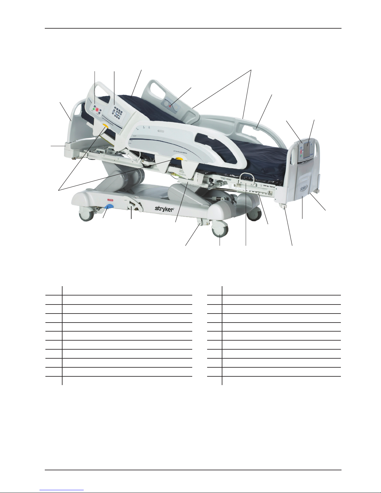
PRODUCT ILLUSTRATION
ST
Introduction
B
O
N
P
H
G
J
I
R
A
D
L
K
E
F
U
A 110V outlet (optional) L Manual backup brake
B Brake control panel (outside siderail) M Mattress retainer
C Caster N Nurse call (inside siderail) (optional)
D CPR release pedal O Motion control panel (outside siderail)
E Foley bag hooks P Pendant holder
F Footboard Q Roller bumpers
G Footboard control panel R Siderail release levers
H Headboard S Siderails
I Head end control panel (optional) T Support surface (optional)
J InTouch touch screen U Zoom drive system (model 2141) (optional)
K Isolated foley bag hooks
C
M
Q
www.stryker.com 2141-209-0 02 RE V H 15
Return To Table of Contents
Page 16
Introduction
CONTACT INFORMATION
Contact Stryker Customer Service or Technical Support at 1-800-327-0770.
Stryker Medical
3800 E. Centre Avenue
Portage, Michigan 49002
USA
To view your operations or maintenance manual online, see https://techweb.stryker.com/.
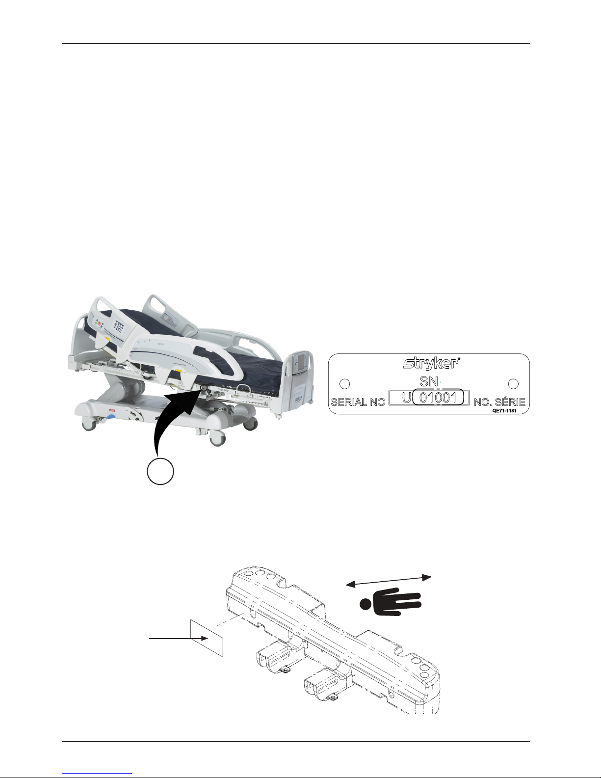
Have the serial number (A) of your Stryker product available when calling Stryker Customer Service or Technical
Support. Include the serial number in all written communication.
SERIAL NUMBER LOCATION
You can find the serial number plate behind the patient right siderail near the foot end of the product.
A
SPECIFICATION LABEL LOCATION
You can find the specification label behind the head end cover on the patient right side of the product.
Return To Table of Contents
16 2141-209 -002 RE V H www.stryker.com
Page 17

Summary of Safety Precautions
Always read and strictly follow the warnings and cautions listed on this page. Service only by qualified personnel.
WARNING
• Improper usage of the product can cause injury to the patient or operator. Operate the product only as described
in this manual.
• Do not modify the product or any components of the product. Modifying the product can cause unpredictable
operation resulting in injury to patient or operator. Modifying the product also voids its warranty.
• Always allow the product to reach room temperature before conducting any setup or testing functional operations
to prevent permanent product damage.
• Always operate the product when all operators are clear of the mechanisms.
• Always plug the product directly into a properly grounded, three-prong receptacle. You can only achieve grounding
reliability when you use a hospital-grade receptacle. This product is equipped with a hospital-grade plug for
protection against electric shock hazard.
• Always properly handle the power cord to avoid the risk of entanglement, damage to the power cord, or potential
shock hazards. If the power cord is damaged, immediately remove the product from service and contact the
appropriate maintenance personnel.
• Do not attach the power cord to any moving parts of InTouch.
• Always unplug the power cord, turn the battery switch to the OFF (O) position, press the N/Brake Off button, and
call maintenance if unanticipated motion occurs.
• Always unplug the product power cord from the wall when using oxygen administering equipment. Possible fire
hazard exists when this product is used with oxygen administering equipment other than nasal, mask type, or half
bed-length tent type.
• The optional iBed® Wireless function is only intended to provide remote information of product status and parameter
conditions. It is not intended to replace patient monitoring protocol.
• The line of sight between an iBed Locator and the head end of bed must be free of obstruction at all times. Any
interference could interrupt communication between the iBed Locator and the IR module.
• You must use an iBed® Wireless compatible footboard with an iBed® Wireless compatible product. You will lose
iBed® Wireless functionality if you use an older version of the footboard.
• You must verify all iBed® Wireless functionality after installation. Verify that the iBed locator communicates the
product’s positions, and that iBed® Wireless communicates with the wireless access point. Failure to do may result
in the loss of information or the transmission of incorrect information.
• You must install the iBed Locators more than 71” apart from one another in the same room (such as in a
semiprivate room with more than one product). Failure to do may result in the product transmitting information to
the incorrect iBed Locator.
• Do not use iBed® Wireless to replace the existing nurse call system. iBed® Wireless products are only intended
to transmit product information. They are not intended to transmit nurse call information.
• Always correctly associate or map the iBed Locator to the room or location to provide accurate location information.
Failure to properly map the iBed Locator to the room or location may result in the product transmitting incorrect
information.
• If you move an iBed Locator after it has been installed and mapped, you must remap to the new room or location
in which it is moved to. You must also remap the iBed Locator if you change the room or location information after
initial installation.
• Always wash your hands after handling a battery. Battery posts, terminals and related accessories contain lead
and lead compounds, chemicals known to the State of California to cause cancer and birth defects or other
reproductive harm. Properly dispose of batteries when required.
• Power save mode activates after one hour on battery power with no motion release switch activation. Bed exit,
scale, and product motion stops operating when the product enters the power save mode.
• Always keep feet clear from the area above the base cover or below the base cover when lowering the product or
when applying the brakes or releasing the brakes.
• Always apply the brakes when a patient is getting in the product or out of the product to avoid instability.
• Always apply the brakes when the patient is unattended.
• Do not apply the electronic brake to slow or stop the product while it is in motion.
• Always keep the product in a low, horizontal position with the siderails fully raised and locked when transporting a
patient.
www.stryker.com 2141-209-0 02 RE V H 17
Return To Table of Contents
Page 18

Summary of Safety Precautions
WARNING (CONTINUED)
• Do not use the Zoom motorized drive when the batteries become discharged. Press N/Brake Off to place the drive
wheel in neutral and push the product manually. Recharge the batteries before using the Zoom motorized drive
again to avoid the risk of battery damage and the drive wheel getting stuck in the down position.
• Use caution while maneuvering the product with the drive wheel activated. Always make sure that there are no
obstacles near the product while the Zoom motorized drive is activated. Injury to the patient, user or bystanders or
damage to the frame or surrounding equipment could occur if you collide with an obstacle.
• Make sure that the brakes are completely released before attempting to move the product. Attempting to move the
product with the brakes applied could result in injury to the patient or operator.
• Do not attempt to move the product manually when you activate the Zoom motorized drive. Always place the drive
wheel into the neutral position and release the brakes before attempting to move the product manually.
• Always make sure that all persons and equipment are away from the area below and around the product before
you activate the CPR release. The CPR release is for emergency use only.
• Always determine the proper use of the restraint straps and restraint strap locations. Improperly adjusted restraint
straps can cause serious injury to a patient. Stryker is not responsible for the type or use of restraint straps on
any of Stryker’s products.
• Only use hospital-grade electric equipment consuming 5A or less with the auxiliary power outlet (optional). The
use of standard electric equipment may bring the current leakage to a level unacceptable for hospital equipment.
• Always keep the siderails in the fully raised position and the sleep surface horizontal in its lowest position unless
the patient’s medical condition dictates otherwise.
• Do not use siderails, with or without their padded covers, as restraint devices to keep patient from exiting the
product. Siderails are designed to keep a patient from inadvertently rolling off the product. It is the responsibility
of the attending medical personnel to determine the degree of restraint necessary to ensure a patient’s safety.
Failure to use the siderails properly could result in serious patient injury.
• Always keep the siderails outside of the oxygen tent.
• The scale system is intended to assist in the monitoring of the patient’s weight variation. Under no circumstances
should its reading be used as sole reference for medical treatment.
• Bed exit is intended only to aid in the detection of a patient exiting the product. It is not intended to replace patient
• onitoring protocol.
• Bed exit is not designed to be used with patients weighing less than 50 lb (23 kg).
• Do not use extension cords with support surfaces. Support surfaces are only intended to be powered by InTouch
with the power cord supplied.
• Do not route cables between the support surface and InTouch.
• Always make sure that all of the patient’s limbs are within the raised and locked siderails when the support surface
is articulating to avoid the risk of patient injury.
• Always center the patient on the support surface. Align the patient’s head toward the headboard before starting
functions. Check the patient frequently to make sure that you maintain the proper positioning.
• Always make sure that the tubing and wiring that is connected to the patient is long enough, stable, and secure
during Lateral Rotation or Turn Assist.
• Always raise all of the InTouch bed siderails before starting Turn Assist or Lateral Rotation functions.
• Do not exceed the safe working load of the Isolibrium support surface. Excess weight could cause unpredictable
safety and performance of this system.
• Always use extra caution when reading radiology images taken of a patient on a support surface because internal
components can cause artifacts and distort readings.
• Do not extubate or intubate patients during Lateral Rotation or Turn Assist. The functions could interfere with the
performance of the ancillary devices.
• Do not zero the bed scales or weigh the patient with Lateral Rotation or Turn Assist active. Motion from the support
surface functions may adversely affect the scale system performance.
• Do not arm bed exit with Lateral Rotation or Turn Assist active. The patient motion and position that results from
the support surface may adversely affect bed exit system performance.
• Do not leave the patient unattended during Turn Assist.
• Always deflate the Isolibrium support surface before beginning CPR.
Return To Table of Contents
18 2141-209 -002 RE V H www.stryker.com
Page 19

Summary of Safety Precautions
WARNING (CONTINUED)
• Always lock the control panel when the patient is unattended, or when a patient’s condition requires greater safety
measures for their condition.
• Do not use iBed® Awareness as a lock indicator for siderails. iBed® Awareness is only intended to detect the
position of the siderails. It is not intended to replace patient monitoring protocol.
• The iBed® Awareness LED light bars are only intended to monitor the product status and parameter conditions. It
is not intended to replace patient monitoring protocol.
• You must physically verify that the siderails are locked before arming iBed® Awareness.
• Always securely set the footboard connector on the optional bed extender into the footboard connector slot at the
foot end of the product.
• Do not pinch the power cord or cables when installing the optional bed extender.
• Do not sit on the optional bed extender. This may cause the product to flip.
• Do not allow the optional line management clip to interfere with a mechanical or electronic mechanism of the
product.
• Do not pinch tubes inside the clip.
• Do not clean the clip with a liquid solution.
• Always adjust the scale or bed exit system if an option is added while the scale or bed exit system is armed.
• Do not place objects that exceed 40 lb (18 kg) onto the optional monitor tray.
• Do not exceed the 150 lb (68 kg) load capacity for the tray support pole.
• Do not clean, service, or perform maintenance while the product is in use.
• Always unplug the power cord and turn the battery switch to the OFF (O) position before cleaning, servicing, or
performing maintenance.
• Always immediately unplug the power cord from the wall outlet when large spills occur near the circuit boards,
cables, and motors. Remove the patient from the product, clean up the fluid, and have service personnel completely
inspect the product. Fluids can cause unpredictable operation and decreased functionality of any electrical product.
Do not return the product to service until it is completely dry and has been thoroughly tested for safe operation.
www.stryker.com 2141-209-0 02 RE V H 19
Return To Table of Contents
Page 20

Summary of Safety Precautions
CAUTION
• Always plug the product into a wall outlet (regulated AC power source) when not in use to maintain a sufficient
battery charge and to maximize product performance while operating on battery power.
• Always immediately replace batteries that have corrosion at the terminals, display cracking, have expanded or
bulging sides, or no longer can maintain a full charge.
• Always use only Stryker authorized batteries when replacing the batteries. Use of non-Stryker batteries may lead
to unpredictable system performance.
• Upon a Battery Low alarm (Battery Low LED on Footboard and audible beep), stop using the Zoom motorized drive
and recharge the batteries immediately. Ignoring the Battery Low alarms may cause your batteries to degrade
quicker than normal and may decrease battery life.
• Always clean Velcro® after each use. Saturate Velcro with disinfectant and allow disinfectant to evaporate.
Appropriate disinfectant for nylon Velcro should be determined by the hospital.
• Do not move footboards from one product to another. Individual products may have different options. Mixing
footboards could result in unpredictable operation of the product.
• Do not use the siderails to move the product. Move the product using the integrated handles in the headboard and
footboard.
• Do not use pencils, pen caps, pen tips, or other pointed objects to tap the touch screen display. Using excessive
pressure may damage the footboard control panel and the touch screen display.
• Always use extra supervision when using a mattress or support surface thicker than six in. (15,4 cm).
• Do not allow sharp objects to come into contact with the support surface that could puncture, tear, or cut the cover.
• Make sure that you set the desired product parameters before enabling iBed® Awareness.
• Do not use accessories that cover the footboard and outside siderail LED light bars.
• Do not turn off the iBed® Awareness alarm. You will lose access to the event manager that displays the compromised
parameter condition.
• Do not hang IV bags that exceed 22 lb (10 kg) onto the IV pole.
• Always make sure that the IV pole is at a low height to pass safely through door openings.
• Do not use the IV pole as a push/pull device.
• Always make sure that the clip is stable when installed.
• Do not inset tubes that are larger than 0.75 in. into the line management clip.
• Always sterilize the clip after each use.
• Always make sure that the clip is stable when installed.
• Always unplug the product before cleaning or servicing.
• Always unplug the product, set the brakes, and place blocks under the litter frame for support when working under
the product.
• Always make sure that you wipe each product with clean water and thoroughly dry each product after cleaning.
Some cleaning products are corrosive in nature and may cause damage to the product if you use them improperly.
If you do not properly rinse and dry the product, a corrosive residue may be left on the surface of the product that
could cause premature corrosion of critical components. Failure to follow these cleaning instructions may void
your warranty.
• Do not steam clean, pressure wash, ultrasonically clean, or immerse any part of the product in water. Exposure to
water may damage the internal electric parts. These methods of cleaning are not recommended and may void this
product’s warranty.
Return To Table of Contents
20 2141-209-0 02 RE V H www.stryker.com
Page 21
Static Discharge Precautions
PROTECTING AGAINST ELECTROSTATIC DISCHARGE (ESD)
CAUTION
• Always use ESD protective equipment before opening antistatic bags and servicing electronic parts.
• Do not place unprotected circuit boards on the floor.
• All electronic service parts will be shipped in static shielding bags. Do not open the bags until you have completed
steps 2 and 3 of the Static Protection Procedure.
Note: Always ship back circuit boards to Stryker in the same antistatic bags that the new boards were
originally shipped in.
The electronic circuits in the product are completely protected from static electricity damage when factory assembled.
Always use adequate static protection when servicing the electronic systems of the product. All service personnel must
use static protection whenever they are touching wires.
Static Antistatic Protection Equipment Includes:
• 1 antistatic wrist strap
• 1 grounding plug
• 1 test lead with a banana plug on one end and an alligator clip on the other end
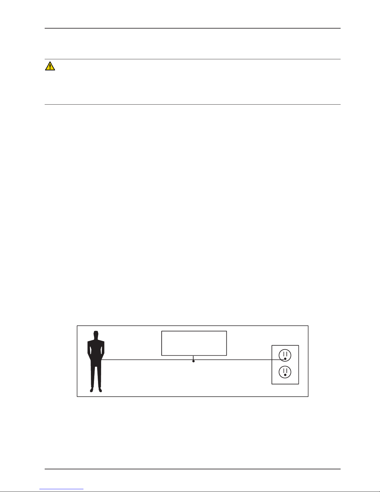
Static Protection Procedure
1. Unplug the power cord from the power source.
2. Insert the grounding plug into a properly grounded hospital grade wall receptacle. Plug the banana plug of the
test lead into the receptacle on the grounding plug. Connect the alligator clip on the other end of the test lead to
a ground point on the bed.
3. Place the static control wrist strap on your wrist. Connect the alligator clip at the other end of the wrist strap cord
to a ground point on the bed.
BED
GROUNDING DIAGRAM
www.stryker.com 2141-209-0 02 RE V H 21
Return To Table of Contents
Page 22

Setup
To unpack your product, see the unpacking instructions that are attached to the product inside of the shipping crate.
WARNING
• Always allow the product to reach room temperature before conducting any setup or testing functional operations
to prevent permanent product damage.
• Always operate the product when all operators are clear of the mechanisms.
• Always properly handle the power cord to avoid the risk of entanglement, damage to the power cord, or potential
shock hazards. If the power cord is damaged, immediately remove the product from service and contact the
appropriate maintenance personnel.
• Do not attach the power cord to any moving parts of InTouch.
• Always unplug the power cord, turn the battery switch to the OFF (O) position, press the N/Brake Off button, and
call maintenance if unanticipated motion occurs.
CAUTION
Always plug the product directly into a properly grounded, three-prong receptacle. You can only achieve grounding
reliability when you use a hospital-grade receptacle. This product is equipped with a hospital-grade plug for protection
against electric shock hazard.
To turn on the product:
1. Plug the power cord into a properly grounded, hospital-grade wall outlet.
2. Turn the battery switch to the ON (|) position.
Before placing the product into service, make sure that these components are working properly:
1. Visually inspect the product for any signs of shipping damage.
2. Flip down and depress the manual brake pedal and make sure that the neutral, drive, and brake functions of the
manual brake pedal hold.
3. Press BRAKE on each control panel and make sure that the neutral, drive, and brake functions of the electronic
brake hold.
4. Test the Zoom drive system (Model 2141).
5. Raise and lower the siderails to make sure that they move smoothly and lock securely in the full up position.
6. Press each button on the head end control panel (optional), motion control panel, brake control panel, footboard
control panel, and patient control pendant (optional) to make sure that each function operates properly.
7. Make sure that the footboard operates properly.
8. Make sure that the scale system operates properly.
9. Make sure that the bed exit system operates properly.
10. Make sure that the CPR release pedal operates properly.
11. Make sure that the support surface operates properly (optional).
12. Make sure that optional accessories are installed and operate as described.
WARNING
Always unplug the product power cord from the wall when using oxygen administering equipment. Possible fire hazard
exists when this product is used with oxygen administering equipment other than nasal, mask type, or half bed-length
tent type.
Return To Table of Contents
22 2141-209-0 02 RE V H www.stryker.com
Page 23

Installation
INSTALLING THE XPRT THERAPY SUPPORT SURFACE (OPTIONAL)
To install the XPRT support surface option onto InTouch, see the installation instructions in the XPRT support surface
operations manual.
INSTALLING THE POSITIONPRO SUPPORT SURFACE (OPTIONAL)
To install the PositionPRO support surface option onto InTouch, see the installation instructions in the PositionPRO
support surface operations manual.
INSTALLING THE ISOLIBRIUM SUPPORT SURFACE (OPTIONAL)
To install the Isolibrium support surface option onto InTouch, see the installation instructions in the Isolibrium support
surface operations manual.
INSTALLING IBED WIRELESS (120V NORTH AMERICAN ONLY) (OPTIONAL)
WARNING
• The optional iBed® Wireless function is only intended to provide remote information of product status and parameter
conditions. It is not intended to replace patient monitoring protocol.
• The line of sight between an iBed Locator and the head end of bed must be free of obstruction at all times. Any
interference could interrupt communication between the iBed Locator and the IR module.
• You must use an iBed® Wireless compatible footboard with an iBed® Wireless compatible product. You will lose
iBed® Wireless functionality if you use an older version of the footboard.
• You must verify all iBed® Wireless functionality after installation. Verify that the iBed locator communicates the
product’s positions, and that iBed® Wireless communicates with the wireless access point. Failure to do may result
in the loss of information or the transmission of incorrect information.
• You must install the iBed Locators more than 71” apart from one another in the same room (such as in a semiprivate room with more than one product). Failure to do may result in the product transmitting information to the
incorrect iBed Locator.
• Do not use iBed® Wireless to replace the existing nurse call system. iBed® Wireless products are only intended to
transmit product information. They are not intended to transmit nurse call information.
You must install the iBed Locator on the wall at the head end of the bed. The iBed Locator communicates with the IR
Module that is installed onto the product.
To mount the iBed Locator, see the installation instructions that were included with your iBed Locator Installation kit.
After you install the iBed Locator, you must configure the wireless connection settings for the iBed Server application.
To configure the iBed Server application, see the installation and configuration instructions in the iBed Server
Installation/Configuration manual.
WARNING
• Always correctly associate or map the iBed Locator to the room or location to provide accurate location information.
Failure to properly map the iBed Locator to the room or location yields incorrect remote information.
• If you move an iBed Locator after it has been installed and mapped, you must remap to the new room or location
in which it is moved to. You must also remap the iBed Locator if you change the room or location information after
initial installation.
If you have any problems during the iBed Wireless installation process, contact Stryker Technical Support at
1–800–327−0770.
www.stryker.com 2141-209-0 02 RE V H 23
Return To Table of Contents
Page 24
Maintenance Menu Guide
The Maintenance Menu is accessed through the Touch Screen and contains additional features of the product. This
menu provides an interface to the user and/or service personnel in order to provide the ability to control and access
maintenance features.
ACCESSING THE CONFIGURATION SCREEN
WARNING
Please ensure patient is not in the bed prior to starting bed calibration. In calibration mode, the software does not control
the interferences between the mechanical parts of the bed. Mechanical damage could occur without supervision. Only
qualified personnel should perform the calibration.
Note
Verify that the bed is on a level surface which does not have any slopes or inclines prior to entering into the calibration
mode.
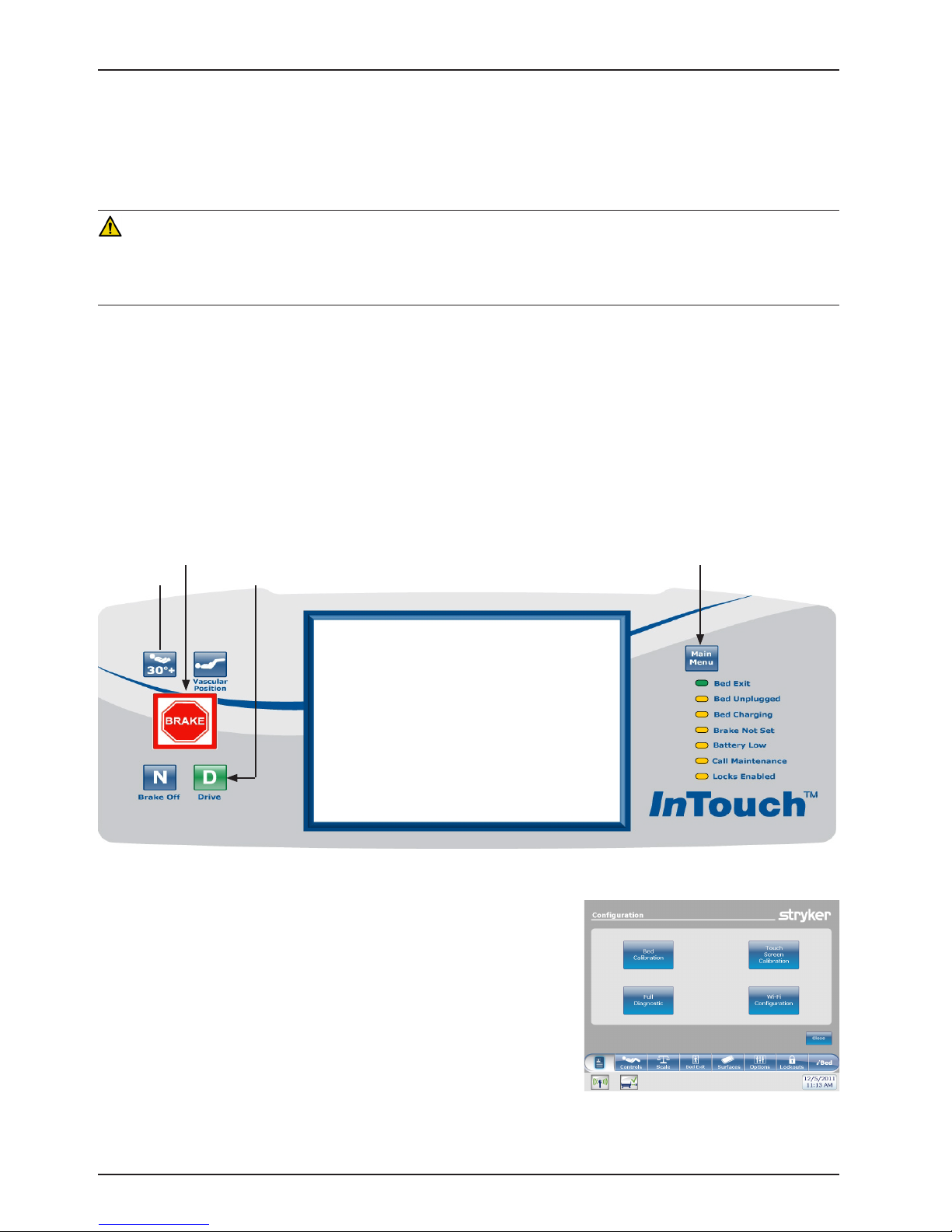
1. Unseat and reseat the footboard and wait until the main control screen is displayed.
2. Push and hold the Main Menu button located in the upper right corner of the footboard control panel
(see Figure 1 below). Continue pressing on the Main Menu button while executing steps 3-5.
3. Push and hold the Brake button for 5 seconds and then release.
4. Push the HOB 30o+ button once and release.
5. Push the Drive button once and release.
6. Release the Main Menu button and you will be taken into the Configuration Screen shown in Figure 2.
HOB
Brake
Main Menu
Drive
Figure 1: Footboard Control Panel
Return To Table of Contents
24 2141-209-0 02 RE V H www.stryker.com
Figure 2: Configuration Screen
Page 25
Maintenance Menu Guide
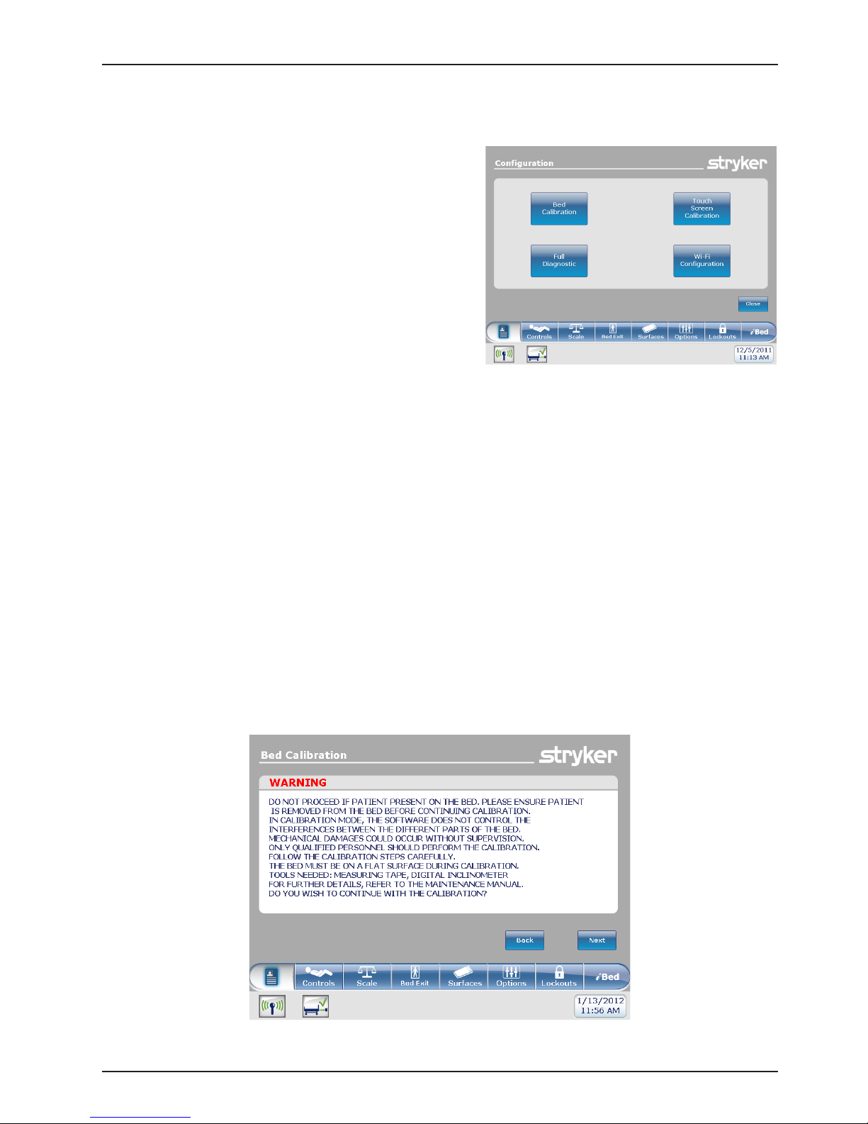
INTOUCH CONFIGURATION SCREEN
The following items A, B, and C are configuration buttons
available and displayed on the Configuration screen
(Figure 3).
A. Bed Calibration
B. Full Diagnostic (see page 36)
C. Touch Screen Calibration (see page 37)
D. Optional Wi-Fi Configuration (see page 38)
The following items D and E are configuration options
available but are not displayed on the Configuration
screen To access these configuration options, follow the
procedures identified on page listed below.
E. Bed Options Configuration (see page 39)
F. Serial Number Configuration (see page 40)
Figure 3: Configuration Screen Menu Items
A. Bed Calibration
Note: During calibration, if the backlight shuts off touch the screen to continue.
1. Connect the bed to an A/C outlet.
2. Place the mattress onto the frame.
3. Press the Bed Calibration button on the Configuration Screen (refer to Figure 3).
4. After pressing the Bed Calibration button, Figure 4 will be displayed. Press “NEXT” to continue with
calibration.
www.stryker.com 2141-209-0 02 RE V H 25
Figure 4: Bed Calibration - WARNING
Return To Table of Contents
Page 26
Maintenance Menu Guide
INTOUCH CONFIGURATION SCREEN (CONTINUED)
A. Bed Calibration (Continued)
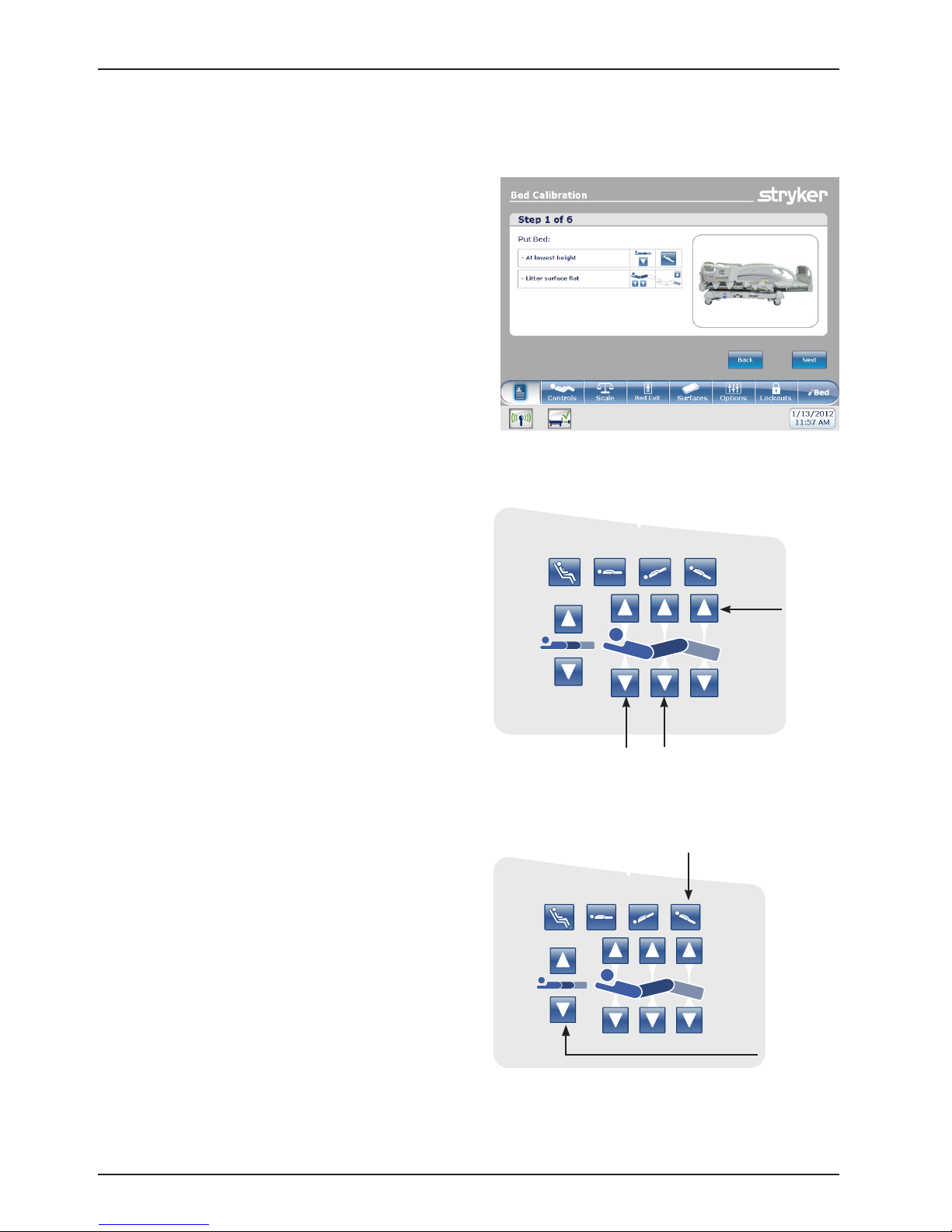
5. After pressing Next to continue calibration,
Figure 5 will appear.
Figure 5: Bed Calibration - Step #1 of 6
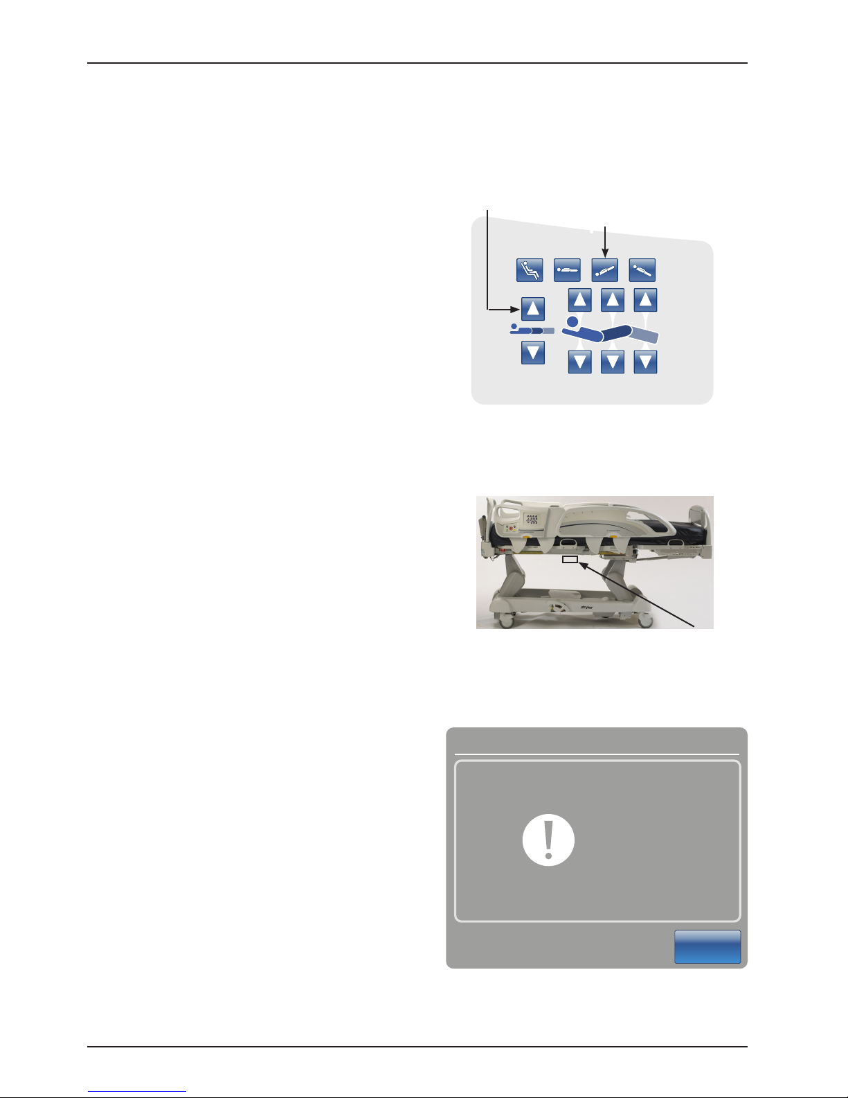
6. Place the Litter surface to a flat position by
pressing simultaneously the Foot Up, Fowler
Down and Gatch Down buttons as shown in
Figure 6.
7. Lower the bed to the lowest position. Press
the Bed Height Down (Head Lift Down) and
Reverse Trendelenburg (Foot Lift Down)
buttons simultaneously as shown in Figure 7.
Foot Up
QDF27-2237
Fowler Down
Gatch Down
Figure 6: HE Siderail Control Panel - (Right Side Shown)
Reverse Trendelenburg
(Foot Lift Down)
Bed Height
Down
(Head Lift
Down)
QDF27-2237
Figure 7: HE Siderail Control Panel - (Right Side Shown)
Return To Table of Contents
26 2141-209 -002 REV H www.stryker.com
Page 27
Maintenance Menu Guide
INTOUCH CONFIGURATION SCREEN (CONTINUED)
A. Bed Calibration (Continued)
Bed Calibration
Do Not
8. Press the Next button when done. The “Do Not
Touch Bed
Touch Bed” screen will appear as shown in Figure
8.
Cancel
Figure 8
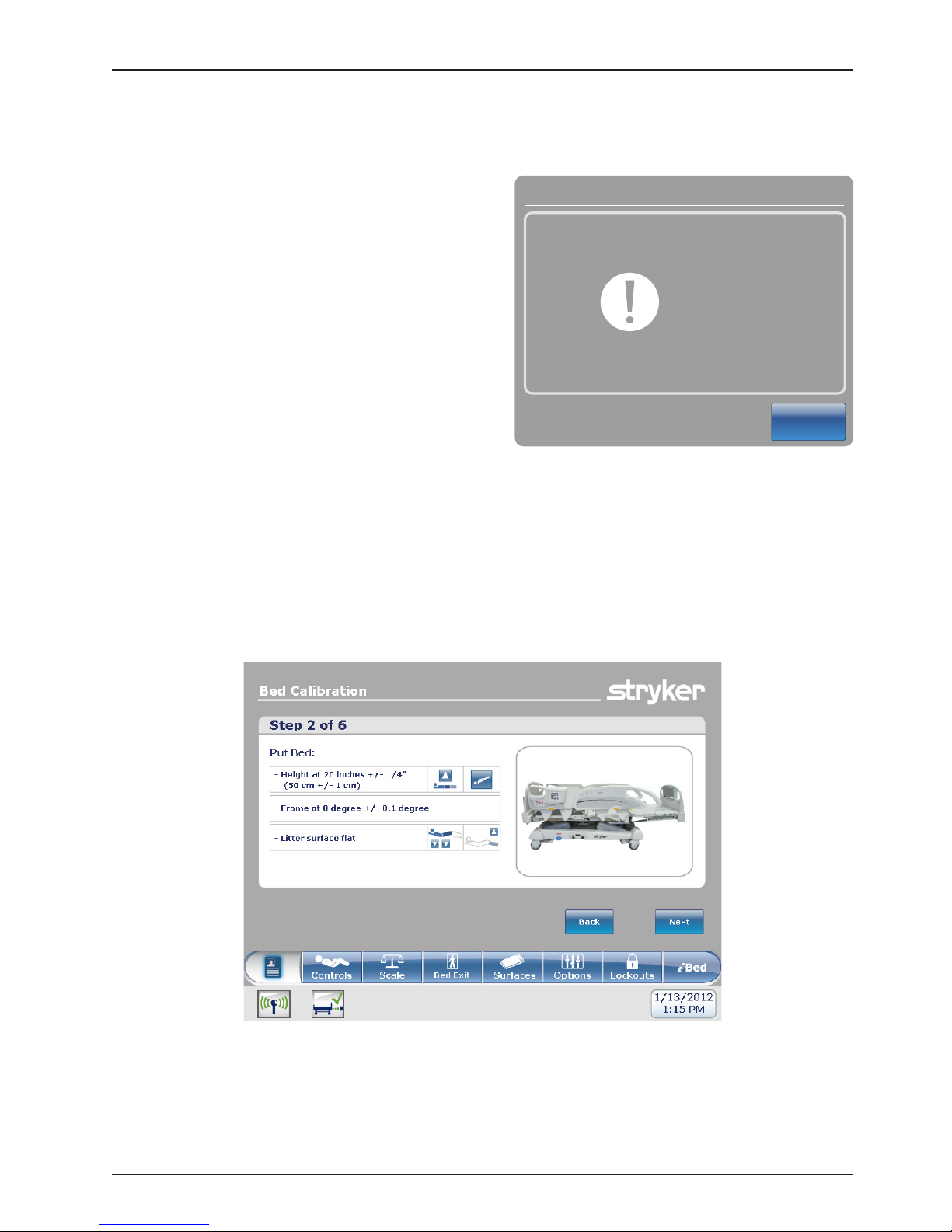
9. When step 1 of the calibration procedure has completed, step 2 of the calibration procedure will begin and
Figure 9 will be displayed.
www.stryker.com 2141-209-0 02 RE V H 27
Figure 9: Bed Calibration - Step 2
Return To Table of Contents
Page 28
Maintenance Menu Guide
INTOUCH CONFIGURATION SCREEN (CONTINUED)
A. Bed Calibration (Continued)
10. Raise the bed height to 20 inches measuring
from the top of the seat section to the floor.
Press the Bed Height Up (Head Lift Up) and
Trendelenburg (Foot Lift Up) buttons as
shown in Figure 10.
11. Standing on either side of the bed at the fowler
section, raise the foot siderail and then position
the digital level/inclinometer on the bottom of
the litter below the mattress retainer (refer to
Figure 11). Using the digital level/inclinometer,
verify the bed is level (0.0 +/- 0.1).
Bed Height Up
(Head Lift Up)
Trendelenburg
(Foot Lift Up)
Figure 10: Head Siderail Control Panel
(Right Side Shown)
QDF27-2237
Note: Cycle power on the digital level/
inclinometer prior to placing it on the
bottom of the litter frame and do not zero/
calibrate the digital level/inclinometer.
12. Press the Next button when done. The “Do
Not Touch Bed” screen will appear as shown
in Figure 12.
Placement
on Litter
Figure 11: Inclinometer placement
Bed Calibration
Do Not
Touch Bed
Cancel
Figure 12: Do Not Touch Bed Screen
Return To Table of Contents
28 2141-209 -002 REV H www.stryker.com
Page 29
Maintenance Menu Guide
INTOUCH CONFIGURATION SCREEN (CONTINUED)
A. Bed Calibration (Continued)
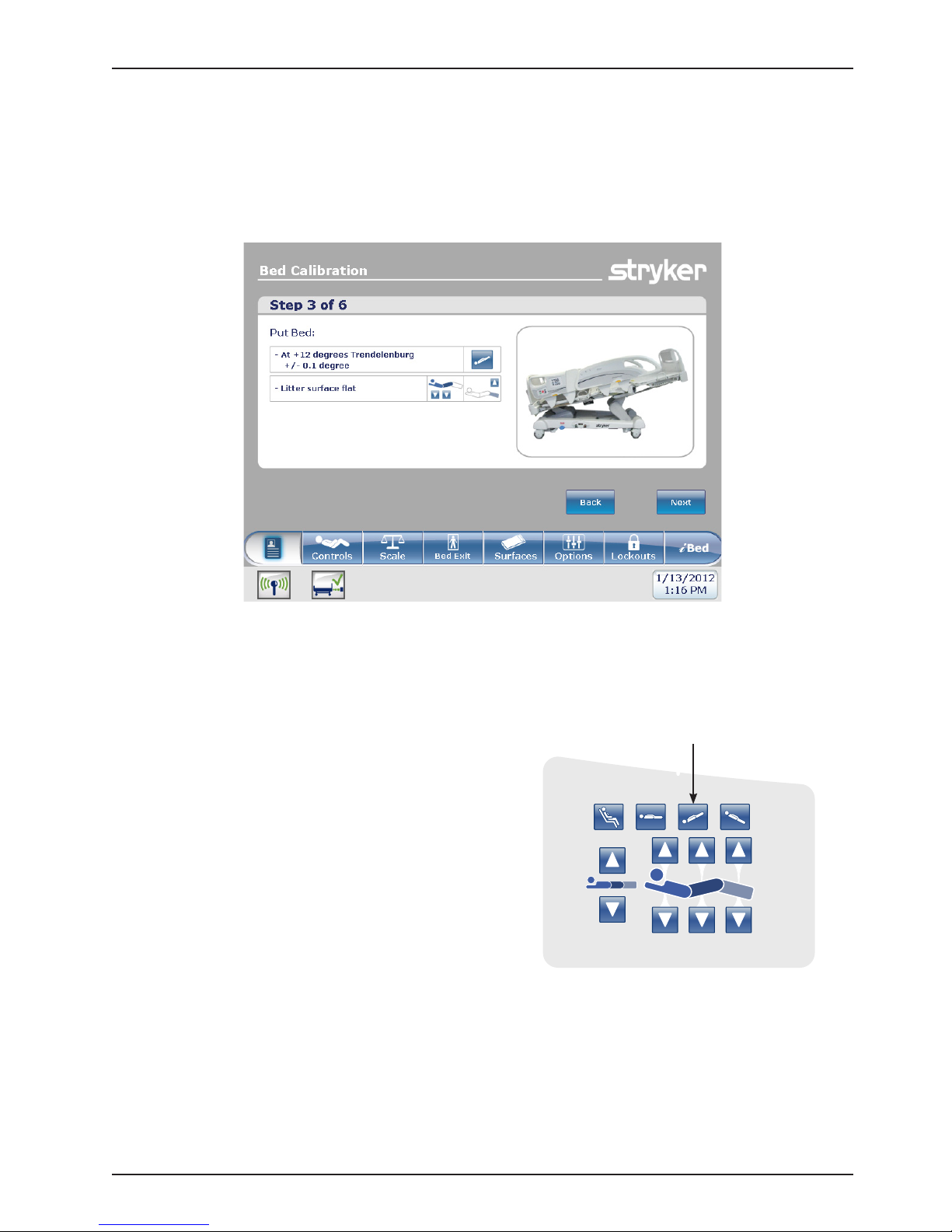
13. When step 2 of the calibration procedure has completed, step 3 of the calibration procedure will begin and
Figure 13 as shown below will appear on the screen.
Figure 13: Bed Calibration - Step 3
14. Place the bed at +12 degrees Trendelenburg by pressing
the Trendelenburg (Foot Lift Up) button as shown in
Figure 14. Verify +12 degrees +/- 0.1 with the inclinometer
you previously placed on the litter frame in step 11.
Trendelenburg
(Foot Lift Up)
QDF27-2237
Figure 14: Head Siderail Control Panel
www.stryker.com 2141-209-0 02 RE V H 29
Return To Table of Contents
Page 30
Maintenance Menu Guide
INTOUCH CONFIGURATION SCREEN (CONTINUED)
A. Bed Calibration (Continued)
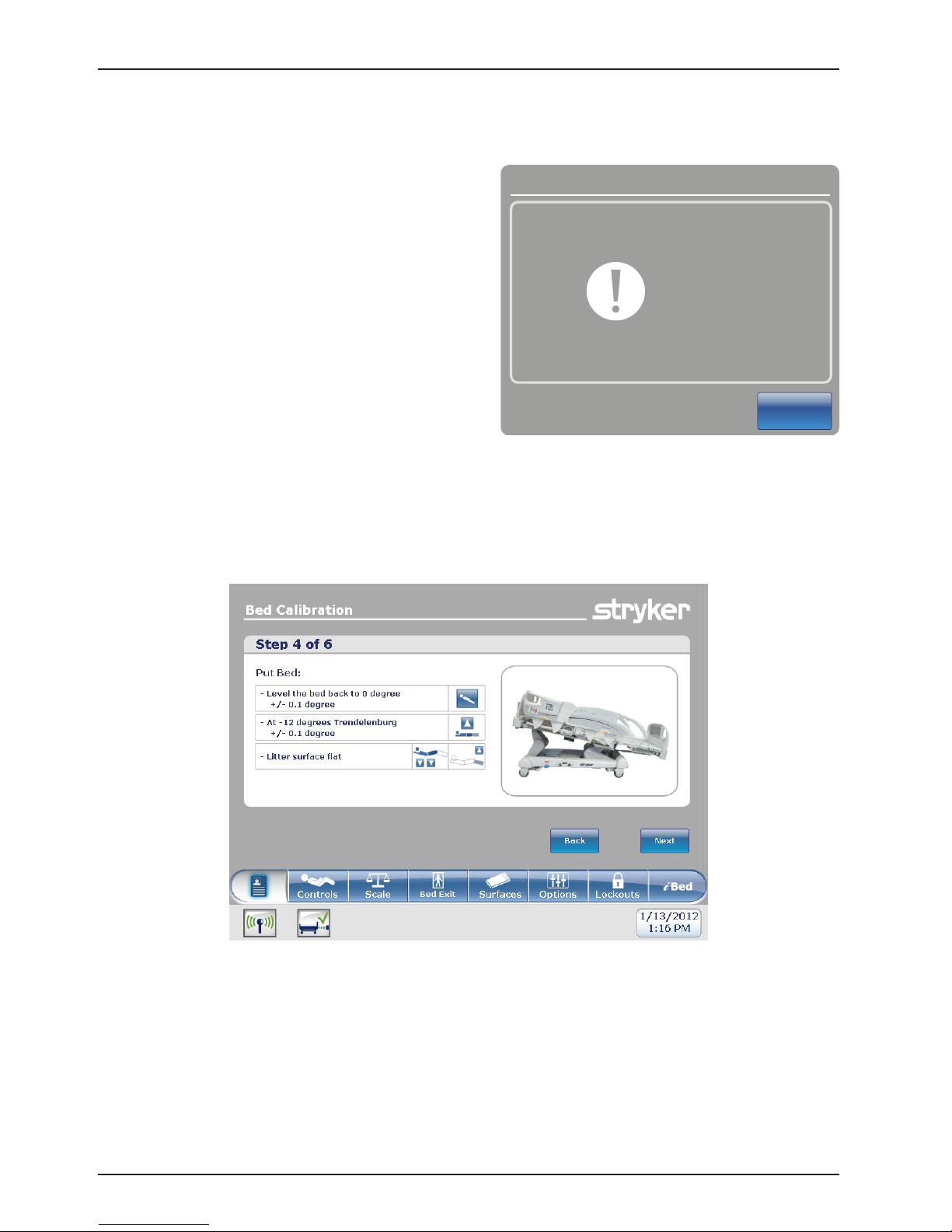
15. Press the Next button when done.
16. The “Do Not Touch Bed” screen will appear as
shown in Figure 15.
Bed Calibration
Do Not
Touch Bed
Cancel
Figure 15: Do Not Touch Bed Screen
17. When step 3 of the calibration procedure has completed, step 4 of the calibration procedure will begin and
Figure 16 will be displayed as shown below.
Figure 16: Bed Calibration - Step 4
Return To Table of Contents
30 2141-209- 0 02 REV H www.stryker.com
Page 31

Maintenance Menu Guide
INTOUCH CONFIGURATION SCREEN (CONTINUED)
A. Bed Calibration (Continued)
18. Level the bed back out to zero degrees by pushing
the Reverse Trendelenburg button until the litter
is level while referencing the inclinometer. Note:
Confirm inclinometer reads zero degrees.
19. Place the bed at -12 degrees Reverse Trendelenburg
by pressing the Bed Height Up (Head Lift Up) button
as shown in Figure 17 below. Verify -12 degrees +/-
0.1 with the inclinometer you previously placed on the
bottom of the litter frame in step 11.
Bed Height Up
(Head Lift Up)
QDF27-2237
Figure 17: Head Siderail Control Panel -
(Right Side Shown)
20. Press the Next button when done.
21. The “Do Not Touch Bed” screen will appear as
shown in Figure 18.
Bed Calibration
Do Not
Touch Bed
Cancel
Figure 18: Do Not Touch Bed Screen
www.stryker.com 2141-209-0 02 RE V H 31
Return To Table of Contents
Page 32

Maintenance Menu Guide
INTOUCH CONFIGURATION SCREEN (CONTINUED)
A. Bed Calibration (Continued)
22. When step 4 of the calibration procedure has completed, step 5 of the calibration procedure will begin and
Figure 19 will appear on the screen as shown below.
Figure 19: Bed Calibration - Step 5
23. Place the bed at the highest height by pressing
simultaneously the Trendelenburg (Foot Lift Up)
button and Bed Height Up (Head Lift Up) button as
shown in Figure 20.
Trendelenburg
(Foot Lift Up)
Bed Height Up
(Head Lift Up)
QDF27-2237
Figure 20: Head Siderail Control Panel -
(Right Side Shown)
Return To Table of Contents
32 2141-209 -002 REV H www.stryker.com
Page 33

Maintenance Menu Guide
INTOUCH CONFIGURATION SCREEN (CONTINUED)
A. Bed Calibration (Continued)
Gatch Up
24. Press the Fowler Up button until the Fowler reaches
the highest height, next press the Gatch Up button
until the Gatch reaches its highest height, lastly
press the Foot Up button until the foot section
reaches its highest height (refer to Figure 21
below). The foot section should be at a flat position.
25. Press the Next button when done.
Fowler Up
Figure 21: Head Siderail Control Panel -
(Right Side Shown)
Bed Calibration
Foot Up
QDF27-2237
26. The “Do Not Touch Bed” screen will appear as
shown in Figure 22.
Do Not
Touch Bed
Cancel
Figure 22: Do Not Touch Bed Screen
Return To Table of Contents
www.stryker.com 2141-209-0 02 RE V H 33
Page 34

Maintenance Menu Guide
INTOUCH CONFIGURATION SCREEN (CONTINUED)
A. Bed Calibration (Continued)
27. When step 5 of the calibration procedure has completed, step 6 of the calibration procedure will begin and
Figure 23 will be displayed as shown below.
Figure 23: Bed Calibration - Step 6
28. Place the bed at the highest height by pressing
simultaneously the Trendelenburg (Foot Lift Up)
button and Bed Height Up (Head Lift Up) button (see
Figure 24).
29. Place the Fowler and Gatch section of the bed at the
highest height by first pressing the Fowler Up button
then the Gatch Up button (See Figure 24).
30. Place the foot at the lowest position by pushing the
Foot Down button until limit is met (see Figure 24) .
CAUTION: The Gatch must be raised to the highest
height prior to running the Foot Down or damage
could occur.
Bed Height Up
(Head Lift Up)
Fowler Up
Trendelenburg
(Foot Lift Up)
Gatch Up
Figure 24: Calibration Complete
Foot Down
QDF27-2237
Return To Table of Contents
34 2141-209 -002 RE V H www.stryker.com
Page 35

Maintenance Menu Guide
INTOUCH CONFIGURATION SCREEN (CONTINUED)
A. Bed Calibration (Continued)
31. When the calibration procedure is completed, Figure 25 will be displayed as shown below.
32. Press the Close button to exit the Calibration Procedure Menu.
33. Level the litter flat using the CPR pedal. Verify all display readings are zero degrees while the bed is at
33” (84 cm) (highest height). Lower the bed to 16” (41 cm) (lowest height) and verify the display readings
maintain a constant reading of zero degrees with no fluctuations. When the bed reaches it lowest height at
16”, verify the display readings are still at zero degrees.
Note: If readings are not all zero, you will need to recalibrate the bed by repeating steps 1-30.
Figure 25: Calibration Complete
Return To Table of Contents
www.stryker.com 2141-209-0 02 RE V H 35
Page 36

Maintenance Menu Guide
INTOUCH CONFIGURATION SCREEN
(CONTINUED)
B. Full Diagnostic
1. From the Configuration Screen, press the
Full Diagnostic button. Figure 26 will appear.
2. The following menu items may be selected
by pressing their button.
a. BOARDS (Figure 27a)
Provides information on the switch
boards and the touch screen’s
software version.
b. ERROR CODES (Figure 27b)
Provides information on errors which
the CPU board has identified.
c. INPUT STATES (F igure 2 7c)
Provides information on the status of
all switches and jumpers on the bed.
d. MOTORS (Figu r e 27d)
Provides information on what a motor is doing when a function button is pushed.
Note: This requires assistance to press the buttons on the head siderails or at the head end control.
e. BUTTONS PRESSED (Figu r e 27e)
Provides information on when the CPU has detected a button being pressed.
Note: This requires assistance to press the buttons on the head siderails or at the head end control.
f. SIGNAL VALUES (Figure 27f)
Provides information on CPU voltages, load cell values, and angle sensor values.
Figure 26: Full Diagnostic Screen
Boards Connected
Nurse A.0 A.1
Nurse (SRH) A.1
Nurse (SRL) A.1
Nurse (SRR) A.1
Power board B.37
Room Interface A.1
TouchScreen D.3
Figure 27a: Board
Motors
Gatch - Reverse
Hilo Foot - Forward
Foot - Forward
Figure 27d: Motor
Close
Close
Figure 27c: Input StatesFigure 27b: Error Codes
Buttons Pressed
Nurse SRR - Trend
Footboard - Hob
Nurse Head - Leg up
Close
Figure 27e: Pressed Buttons Figure 27f: Signal Values
Return To Table of Contents
36 2141-209-0 02 REV H www.stryker.com
Page 37

Maintenance Menu Guide
INTOUCH CONFIGURATION SCREEN (CONTINUED)
C. Touch Screen Calibration
Ensure patient is not present on the bed before performing the Touch Screen Calibration.
1. From the Configuration Screen, press the Touch Screen Calibration button. Figure 28 will appear.
NOTE: If the touch screen will not respond, you will need to push the HOB 300+, Brake and Drive buttons
on the footboard at the same time (this will enable you to get directly into the touch screen calibration).
CAUTION: When pushing the buttons above the fowler, brakes, or drive, actuators may activate.
2. Carefully press and briefly hold a stylus or your finger on the center of the cross hair shown on the screen.
3. Repeat as the target moves around the screen. There will be five different locations to press: center, lower
right, upper right, upper left, and lower left.
4. When the last cross hair has been touched, Figure 29 displays ‘New calibration settings have been measured’.
5. Tap the screen to register saved data.
6. If you do not want to save the new data, wait for 30 seconds to cancel saved data and keep the current setting.
Figure 28: Touch Screen Calibration: Start Figure 29: Touch Screen Calibration: Completed
NOTE: The TOUCH SCREEN CALIBRATION SCREEN is a validation of the touch screen’s calibration. When the
user presses anywhere on the screen, the coordinates x and y are displayed on the lower part of the screen.
Return To Table of Contents
www.stryker.com 2141-209-0 02 RE V H 37
Page 38

Maintenance Menu Guide
INTOUCH CONFIGURATION SCREEN (CONTINUED)
D. Optional Wi-Fi Configuration
CAUTION
These settings should only be modified by trained personnel. Changing these settings may disable the wireless feature.
These settings should only be changed or updated with the aid of the hospital’s IT department or the appropriate
maintenance personnel.
1. From the Configuration Screen, tap Wi-Fi Configuration to configure wireless settings for the bed.
2. Tap Wi-Fi OFF to toggle the wireless network connection on.
3. Tap the appropriate tab, and then tap the pencil icon to configure the network settings (Figure 30 - Figure 33).
4. Tap Save to save the network settings.
5. After saving the configured network settings, a power cycle notification appears.
6. Unplug the power cord from the wall outlet.
7. Turn the battery switch to the OFF (O) position.
8. Plug the power cord into the wall outlet.
9. Turn the battery switch to the ON (|) position.
Note: After you cycle power, InTouch reboots to the Patient Information screen.
Figure 30: Network Parameters
Figure 32: Security
Return To Table of Contents
38 2141-209- 0 02 REV H www.stryker.com
Figure 31: User Authentication
Figure 33: Advanced
Page 39

Maintenance Menu Guide
INTOUCH CONFIGURATION SCREEN (CONTINUED)
E. Bed Options Configuration
Access the configuration screen as shown on page 24. Once in the configuration screen, follow the steps below to
access the options screen or the serial number screen.
To access the Bed Options screen:
1. Press and hold the HOB 30 button and the BRAKE button at the same time for 5 seconds, then release both
buttons. The Bed Options screen (Figure 34) will be displayed.
NOTE: When the European Community message window displays, push the Close button to close out
of the message. That is not applicable in this configuration.
Figure 34: Bed Options screen
2. Select all of the options shown on the Bed Options screen that apply to the bed configuration then, press Continue.
NOTE: In Figure 34, the options selected are iBed, iAudio, iDoc and Wi-Fi. All of the options selected will turn
green.
3. After pressing Continue in step 2, a confirmation screen
as shown in Figure 35 will be displayed verifying the
options you selected.
a. If the options on the confirmation screen do not
match the options on the bed, press the Back
button.
b. If the options on the confirmation screen match the
options on the bed, press the OK button.
4. After pressing the OK button, the options will be saved
and the screen will return to the configuration screen.
Press the Close button to close the configuration
screen.
5. After pressing the Close button, a cycle power screen
(Figure 38) will be displayed stating to cycle power on
the bed.
6. To cycle power on the bed, turn the battery disconnect
switch to OFF (O) then unplug the power cord from the
wall outlet. Plug the power cord back into the wall outlet
then turn the battery disconnect switch back ON (|).
7. Test bed functionality prior to returning the bed into service.
Figure 35: Bed Options Confirmation Screen
www.stryker.com 2141-209-0 02 RE V H 39
Return To Table of Contents
Page 40

Maintenance Menu Guide
INTOUCH CONFIGURATION SCREEN (CONTINUED)
F. Serial Number Configuration
To access the Serial Number screen:
1. Press and hold the HOB 30 button and the Vascular Position button at the same time for 5 seconds then release
both buttons. The Bed Configuration - Serial Number screen (Figure 36) will be displayed.
Pencil icon
Press to edit
Figure 36: Bed Configuration Serial Number Screen
2. Enter or confirm the serial number of the bed (Figure 36).
a. To enter the serial number:
i. Press the pencil button located to the right of the serial
number field. The Edit screen will be displayed.
ii. Enter the serial number of the bed in the serial number
field, then press the OK button. You will be returned to
the serial number main screen as shown in Figure 36.
iii. Press the Continue button and proceed to step 3.
b. To confirm the serial number:
i. Review the serial number displayed in the serial number
field.
ii. If serial number is correct, press the Back button and
proceed to step 6.
iii. If the serial number is incorrect, press the pencil icon
button to open the Edit screen then enter the correct
serial number.
iv. Press the OK button and you will be returned to the
serial number main screen.
v. Press the Continue button and proceed to step 3.
3. After pressing the Continue button, the serial number will be
saved and the serial number confirmation screen (Figure 37) will
be displayed. Press the OK button.
4. After pressing the OK button, a cycle power screen (Figure 38)
will be displayed stating to cycle power on the bed.
5. To cycle power on the bed, turn the battery disconnect switch to
OFF (O) then unplug the power cord from the wall outlet. Plug
the power cord back into the wall outlet then turn the battery
disconnect switch back ON (|).
6. Test bed functionality prior to returning the bed into service.
Figure 37: Serial Number
Confirmation Screen
Figure 38: Cycle Power Screen
Return To Table of Contents
40 2141-209 -002 REV H www.stryker.com
Page 41

Maintenance Menu Guide
A B
ACCESSING THE ISOLIBRIUM DIAGNOSTIC MENU
WARNING
• Electrical shock risk. Refer all servicing to qualified personnel.
• Do not perform diagnostic test with a patient or other weight on the support surface.
CAUTION
Do not touch the support surface while performing diagnostics test. Failure to do so could lead to inaccurate diagnostic
results.
Note: Make sure that you plug the support surface power
cord into the InTouch auxiliary mattress outlet (A) and the
integration cable to the mattress connector (B) (Figure
39).
The service display and its functions are for use by
authorized service personnel only to avoid the risk of
equipment malfunction. The entry to this menu is through a
key combination in the Support Surface menu.
To access the diagnostic menu:
Figure 39: InTouch auxiliary mattress outlet and
integration cable
1. Unplug the InTouch bed and turn the battery switch to off and wait one minute.
2. Turn the battery switch to on and plug the InTouch bed into a wall outlet.
3. Tap Support Surfaces.
4. Enter the following key combination within 5 minutes of the support surface connection (Figure 40):
a. Lock (A) (lock is activated)
b. Low Air Loss (B) (press and hold for a minimum of 5 seconds)
c. Therapy History (C) (press and hold for a minimum of 5 seconds)
B
Figure 40: Diagnostic Entry Combination
5. If you have entered into the diagnostic menu and need to exit, tap X (Figu r e 41).
A
C
www.stryker.com 2141-209-0 02 RE V H 41
Figure 41: Diagnostic Main Screen Sample
Return To Table of Contents
Page 42

Maintenance Menu Guide
REVIEWING ACTIVE ISOLIBRIUM ERRORS
Note: For Isolibrium error codes, see the Isolibrium operations/maintenance manual.
To enter the Active Errors screen, tap the Active Errors tab on the Service Diagnostic screen (Figure 42).
Figure 42: Active Errors
A list of the active errors are displayed (Figure 42). A maximum of five active errors are displayed simultaneously, and
are ordered by priority.
REVIEWING AND CLEARING ISOLIBRIUM ERROR HISTORY
To enter the Error History screen, tap the Error History tab on the Diagnostic Screen (Figure 43).
Figure 43: Diagnostic Screen
The error list is ordered from the oldest entry to the newest, with a maximum of 10 errors.
To clear the Error History screen, tap Clear Error History on the Diagnostic screen (Figure 43).
Notes
• Always tap Clear Error History after troubleshooting is complete
• If you clear the error history while there is an active error, the active error does not show in the Error History tab
until the active error is fixed.
Return To Table of Contents
42 2141-209-0 02 RE V H www.stryker.com
Page 43

Maintenance Menu Guide
VIEWING ADVANCED SIGNAL VALUES FOR ISOLIBRIUM
The Advanced Signal Values screen displays the complete list of signal values of the support surface. The screen
displays the actual and goal pressure values. For other non-pressure signals, only the actual values are displayed.
To enter the Advanced Signal Values screen, tap Advanced Signal Values on the Diagnostics screen (Figure 44).
Figure 44: Diagnostic Main Screen - Sample
To exit the Advanced Signal Values screen, tap Back to return to the Diagnostics screen (Figure 45).
Figure 45: Advanced Signal Values
www.stryker.com 2141-209-0 02 RE V H 43
Return To Table of Contents
Page 44

Maintenance Menu Guide
RUNNING A DIAGNOSTIC TEST FOR ISOLIBRIUM
WARNING
Do not perform diagnostic test with a patient or other weight on the support surface.
CAUTION
Do not touch the support surface while performing diagnostics test. Failure to do so could lead to inaccurate diagnostic
results.
Notes
• The results of the test will not be displayed until all tests have been completed.
• No results will be displayed if the tests are canceled.
• Other diagnostic functions are disabled while the diagnostic test is running.
The diagnostic test runs seven tests at one time on the support surface and take approximately 45 minutes to complete.
They include the following:
• Seat Left
• Seat Right
• Back Left
• Back Right
• Turn Left
• Turn Right
• Low Air Loss
To run diagnostics, tap start on the lower portion of the Diagnostics screen (Figure 46).
Figure 46: Diagnostic Main Screen - Sample
Return To Table of Contents
44 2141-2 09 -002 REV H www.stryker.com
Page 45

Maintenance Menu Guide
RUNNING A DIAGNOSTIC TEST FOR ISOLIBRIUM (CONTINUED)
Note: Diagnostics running (Figure 47) appears to indicate that the diagnostic test is in progress.
To cancel diagnostics, tap stop on the lower portion of the Diagnostics screen (Figure 47).
Figure 47: Diagnostic Main Screen - Sample
When the test is complete, the results of each test section is indicated by a red cross when there is a failure or a green
check mark when successful (Figure 48).
Note: When a failure is first detected, all following pressure tests will be marked as a failure.
Figure 48: Diagnostic Test Result - Sample
www.stryker.com 2141-209-0 02 RE V H 45
Return To Table of Contents
Page 46

Cleaning
WARNING
• Do not clean, service, or perform maintenance while the product is in use.
• Always unplug the power cord and turn the battery switch to the OFF (O) position before cleaning, servicing, or
performing maintenance.
• Always immediately unplug the power cord from the wall outlet when large spills occur near the circuit boards,
cables, and motors. Remove the patient from the product, clean up the fluid, and have service personnel completely
inspect the product. Fluids can cause unpredictable operation and decreased functionality of any electrical product.
Do not return the product to service until it is completely dry and has been thoroughly tested for safe operation.
CAUTION
• Always unplug the product before cleaning or servicing.
• Always unplug the product, set the brakes, and place blocks under the litter frame for support when working under
the product.
The recommended cleaners for this product’s surfaces include the following:
Quaternary Cleaners (active ingredients - ammonium chloride)
Phenolic Cleaners (active ingredient - o-phenylphenol)
Chlorinated Bleach Solution (5.25% - less than 1 part bleach to 100 parts water)
Hand wash all surfaces of the product with warm water and mild detergent. Dry thoroughly.
Avoid oversaturation and make sure the product does not stay wet longer than the chemical manufacturer’s guidelines
for proper disinfecting.
CAUTION
• Always make sure that you wipe each product with clean water and thoroughly dry each product after cleaning.
Some cleaning products are corrosive in nature and may cause damage to the product if you use them improperly.
If you do not properly rinse and dry the product, a corrosive residue may be left on the surface of the product that
could cause premature corrosion of critical components. Failure to follow these cleaning instructions may void
your warranty.
• Do not steam clean, pressure wash, ultrasonically clean, or immerse any part of the product in water. Exposure
to water may damage the internal electric parts. These methods of cleaning are not recommended and may void
this product’s warranty.
• Always clean Velcro® after each use. Saturate Velcro with disinfectant and allow the disinfectant to evaporate.
Appropriate disinfectant for nylon Velcro should be determined by hospital protocol.
CLEANING A SUPPORT SURFACE
To clean and disinfect a support surface, see the cleaning and disinfecting instructions in the support surface operations
manual.
Return To Table of Contents
46 2141-209 -002 REV H www.stryker.com
Page 47

Preventive Maintenance
At a minimum, check all items listed during annual preventive maintenance for all Stryker Medical products. You may
need to perform preventive maintenance checks more frequently based on your level of product usage.
Remove product from service before performing preventive maintenance. Preventive maintenance should only be
performed by trained or certified personnel.
Notes
• Clean and disinfect the exterior of the support surface before inspection, if applicable.
• For Isolibrium preventive maintenance items, see the Isolibrium operations/maintenance manual.
Inspect the following items:
_____
_____
_____
_____
_____
_____
_____
_____
_____
_____
_____
_____
_____
_____
_____
_____
_____
_____
_____
_____
_____
_____
_____
_____
_____
_____
_____
_____
_____
_____
_____
_____
_____
_____
_____
_____
_____
_____
_____
_____
_____
_____
_____
All welds and all fasteners are secure
Tubing or sheet metal for bends or breaks
Casters are free of debris
Casters are secure and swivel properly
Casters lock securely by depressing the brake pedal
Manual and electric brakes apply and release properly
Brake Not Set LED on the footboard and head end siderails when brakes are not engaged
Locking steer caster engages and disengages properly (model 2131)
Steer caster latches properly
Fowler operates properly
Litter up/down operates properly
Trend operates properly
IV pole is intact and operating properly (optional)
Support surface cover after each use
Support surface cover for rips or cracks
Headboard, footboard, and siderail panels for cracks or splits
All covers are not damaged and are not producing sharp edges
Night light operating properly
CPR release operating properly
All siderail motion functionality
Siderails move, latch, and stow properly
Siderail switches working properly (iBed Awareness option)
iBed Awareness light bars on footboard and siderails are working properly (iBed Awareness option)
All functions on head end siderails working properly (including LEDs)
All functions on footboard working properly (buttons, touch screen display, and LEDs)
Touch screen is accurately calibrated
Product is accurately calibrated
Scale and bed exit system operating properly
Drive wheel to make sure it is operating properly (model 2141 — Zoom option)
Motion release switches working properly (model 2141 — Zoom option)
Head end Zoom handle functionality operates properly (2141 model only)
Batteries for replacement (every two years) (use only QDF9188 for battery replacement)
Batteries for corrosion at the terminals, cracking, expanded or bulging at the sides, or can no longer maintain a
full charge
Nurse call functionality (optional)
Lubricate where required
Pendant for any physical damage
Power cord not frayed
Cables not worn or pinched
All electrical connections tight
www.stryker.com 2141-209-0 02 RE V H 47
Return To Table of Contents
Page 48

Preventive Maintenance
_____
_____
_____
_____
_____
_____
_____
_____
Serial Number:
Completed by: _______________________________________ Date: _________________
All grounds secure to the frame
Ground impedance not more than 100 mΩ (milliohms)
Current leakage not more than 300 μA (microamps)
Ground chains are clean, intact, and have at least two links touching the floor
Enclosure is free from wear, tear, stresses and mechanical damage
No rust or corrosion of parts
Labels for legibility, proper adherence, and integrity
iBed Wireless Module and IR Module are intact and footboard icons are displaying (iBed Wireless option)
Return To Table of Contents
48 2141-209-0 02 RE V H www.stryker.com
Page 49

Quick Reference Replacement Parts
These parts are currently available for purchase. Call Stryker Customer Service: 1–800–327–0770 for availability and
pricing.
Part Name Part Number
Electrical Components
Actuator, Brake QDF27-1227
Actuator, Foot QDF27-1216
Actuator, Fowler QDF27-1214
Actuator, Gatch QDF27-1215
Actuator, Lift, Foot End QD F 2 7-1251
Actuator, Lift, Head End QD F 2 7-1252
Angle Sensor, Foot, Fowler, Base, Gatch, Lift 27-2477
Batteries (Replace both at same time) QDF9188
Board, CPU/Power QDF75-0440
Board, Drive (2141 Zoom® Only) QD F 2 7-14 3 0
Board, Headwall QDF75-0270
Board, Brake Control QDF27-1097
Board, Footboard, Function Section/LED’s QDF75-0010
Board, Siderail, Outside (Bed Motion) QDF27-1099
Board, Wi-Fi 27-2775
Fuse, 8Amp Ceramic QDF2120
Fuse, 10Amp, Main Power QDF8078
Fuse, 25Amp Cartridge QDF2119
Load Cell QD F 2 7-1372
Motor, Drive (2141 Zoom® Only) QD F 2 7-14 4 5
Motor, Drive Actuator (2141 Zoom® Only) 27-2593
Position Sensor, Brake/Brake Off/Drive QDF27-2024
Power Cord 27-2782
Speaker, Right Siderail QDF27-2216
Speaker, Left Siderail QDF27-2175
Touch Screen, Footboard 27-2757
Transformer (120VAC) QDF27-2038
www.stryker.com 2141-209-0 02 RE V H 49
Return To Table of Contents
Page 50

Quick Reference Replacement Parts
Part Name Part Number
Other Components
Caster (2141 Model - all four casters) (2131 Model - both head end casters) RD27-1970
Caster, Steer (2131 Model Only - both foot end casters) RD27-19 7 1
Headboard Assembly 27-25 8 3 K
Footboard Assembly without iBed 27-2285K
Footboard Assembly with iBed and iAudio 27-2824K
Footboard Assembly with iBed and Wi-Fi 27-2827K
Footboard Assembly with iBed, without iAudio 27-2826 K
Return To Table of Contents
50 2141-209-0 02 RE V H www.stryker.com
Page 51

Troubleshooting
Notes:
• See the Bed Circuit Boards section for an outline of InTouch PCBs and voltage test points.
• For Isolibrium troubleshooting, see the Isolibrium operations/maintenance manual.
BED TROUBLESHOOTING
Problem / Failure Recommended Action
No Power to Bed.
(On wall voltage 120VAC)
COUNTRY VOLTAGE (CV) TABLE
VO LTAG E FUSE
100V 10A
110V 10A
120V 10A
1. Verify the bed is plugged into a functional wall outlet.
A. Check your country voltage option at wall outlet.
I. If your country voltage option is present, go to step 2.
II. If 1your country voltage option is not present, contact
hospital maintenance staff and try another outlet.
2. Verify the Bed main power fuses are good, located in drawer where
power cord plugs into the bed.
A. Check for continuity of each 10A fuse.
I. If each fuse (see CV Table) is good, go to step 3.
II. If either fuse (see CV Table) does not have continuity,
replace the fuse.
200V 10A
220V 10A
230V 10A
240V 10A
3. Verify there is power at the transformer connection (J11) on the
CPU/Power board at the foot end.
A. Check for 24VAC at J11 between the blue and red wires.
I. If 24VAC is present, go to step 4.
II. If 24VAC is not present, check the 25 Amp fuse in the fuse
holder on the red wire from the transformer. If bad, replace
the fuse.
III. If 24VAC is not present, check the power cable quick
connection going to the transformer for (see CV Table)
VAC. If no voltage, follow the cable and repair or replace
the damaged component.
IV. If (see CV Table) VAC is present, replace the transformer
assembly.
4. A. Check for 30VAC at J11 between the yellow and orange wires
for the transformer.
I. If 30VAC is present, go to step 5.
II. If 30VAC is not present, check the power cable quick
connection going to the transformer for (see CV Table)
VAC. If no voltage, follow the cable and repair or replace
the damaged component.
III. If (see CV Table) VAC is present, replace the transformer
assembly.
5. A. Check fuse F1 on the CPU/Power board.
I. If fuse is good, replace CPU/Power board.
II. If fuse does not have continuity, replace the fuse (littelfuse
215008.P).
www.stryker.com 2141-209-0 02 RE V H 51
Return To Table of Contents
Page 52

BED TROUBLESHOOTING
Problem / Failure Recommended Action
No Bed Up Motion.
No Bed Down Motion.
FOOT
HEAD
FOOT
Troubleshooting
1. Put the bed into the Bed Calibration menu.
A. Using one of the head siderails, push the trend button.
I. If the foot lift motor runs up, recalibrate the bed (refer to
the Bed Calibration procedures located on page 25).
a. If recalibration does not work, replace the litter angle
sensor and recalibrate.
II. If the foot lift motor does not run up, check for 24VDC at
connector J6 while pressing the trend button. Black lead
to pin 1, red lead to pin 2.
a. If voltage is present, replace the motor.
b. If voltage is not present, replace the CPU/Power board.
1. Put the bed into the Bed Calibration menu.
A. Using one of the head siderails, push the bed up button.
I. If the head lift motor runs up, recalibrate the bed (refer to
the Bed Calibration procedures located on page 25).
a. If recalibration does not work, replace the litter angle
sensor and recalibrate.
II. If the head lift motor does not run up, check for 24VDC at
connector J4 while pressing the trend button. Black lead
to pin 1, red lead to pin 2.
a. If voltage is present, replace the motor.
b. If voltage is not present, replace the CPU/Power board.
1. Put the bed into the Bed Calibration menu.
A. Using one of the head siderails, push the reverse trend button.
I. If the foot lift motor runs down, recalibrate the bed (refer
to the Bed Calibration procedures located on page 25).
a. If recalibration does not work, replace the litter angle
sensor and recalibrate.
II. If the foot lift motor does not run down, check for 24VDC
at connector J6 while pressing the reverse trend button.
Red lead to pin 1, black lead to pin 2.
a. If voltage is present, replace the motor.
b. If voltage is not present, replace the CPU/Power board.
HEAD
Return To Table of Contents
52 2141-209 -002 REV H www.stryker.com
1. Put the bed into the Bed Calibration menu.
A. Using one of the head siderails, push the bed down button.
I. If the head lift motor runs down, recalibrate the bed (refer
to the Bed Calibration procedures located on page 25).
a. If recalibration does not work, replace the litter angle
sensor and recalibrate.
II. If the head lift motor does not run down, check for 24VDC
at connector J4 while pressing the trend button. Red lead
to pin 1, black lead to pin 2.
a. If voltage is present, replace the motor.
b. If voltage is not present, replace the CPU/Power board.
Page 53

Troubleshooting
BED TROUBLESHOOTING
Problem / Failure Recommended Action
No Fowler Up Motion. 1. Put the bed into the Bed Calibration menu.
A. Using one of the head siderails, push the fowler up button.
I. If the fowler motor runs up, recalibrate the bed (refer to
the Bed Calibration procedures located on page 25).
a. If recalibration does not work, replace the fowler angle
sensor and recalibrate.
II. If the fowler motor does not run up, check for 24VDC at
connector J5 while pressing the fowler up button. Black
lead to pin 1, red lead to pin 2.
a. If voltage is present, replace the motor.
b. If voltage is not present, replace the CPU/Power
board.
No Fowler Down Motion. 1. Put the bed into the Bed Calibration menu.
A. Using one of the head siderails, push the fowler down button.
I. If the fowler motor runs down, recalibrate the bed (refer to
the Bed Calibration procedures located on page 25).
a. If recalibration does not work, replace the fowler angle
sensor and recalibrate.
II. If the fowler motor does not run down, check for 24VDC
at connector J5 while pressing the fowler down button.
Red lead to pin 1, black lead to pin 2.
a. If voltage is present, replace the motor.
b. If voltage is not present, replace the CPU/Power
board.
No Gatch Up Motion. 1. Put the bed into the Bed Calibration menu.
A. Using one of the head siderails, push the gatch up button.
I. If the gatch motor runs up, recalibrate the bed (refer to
the Bed Calibration procedures located on page 25).
a. If recalibration does not work, replace the gatch angle
sensor and recalibrate.
II. If the gatch motor does not run up, check for 24VDC at
connector J3 while pressing the gatch up button. Red
lead to pin 1, black lead to pin 2.
a. If voltage is present, replace the motor.
b. If voltage is not present, replace the CPU/Power
board.
www.stryker.com 2141-209-0 02 RE V H 53
Return To Table of Contents
Page 54

Troubleshooting
BED TROUBLESHOOTING
Problem / Failure Recommended Action
No Gatch Down Motion. 1. Go to the Bed Calibration menu.
A. Using one of the head siderails, push the gatch down button.
I. If the gatch motor runs down, recalibrate the bed (refer to
the Bed Calibration procedures located on page 25).
a. If recalibration does not work, replace the gatch angle
sensor and recalibrate.
II. If the gatch motor does not run down, check for 24VDC
at connector J3 while pressing the gatch down button.
Black lead to pin 1, red lead to pin 2.
a. If voltage is present, replace the motor.
b. If voltage is not present, replace the CPU/Power
board.
No Foot Up Motion. 1. Put the bed into the Bed Calibration menu.
A. Using one of the head siderails, push the foot up button.
I. If the foot motor runs up, recalibrate the bed (refer to the
Bed Calibration procedures located on page 25).
a. If recalibration does not work, replace the foot angle
sensor and recalibrate.
II. If the foot motor does not run up, check for 24VDC at
connector J1 while pressing the foot up button. Red lead
to pin 1, black lead to pin 2.
a. If voltage is present, replace the motor.
b. If voltage is not present, replace the CPU/Power
board.
No Foot Down Motion. 1.2.Ensure there is no debris in the foot end traction sockets. If debris
exists, remove it and press the foot down button. If the foot motor
still does not run down, proceed to step 2.
Put the bed into the Bed Calibration menu.
A. Using one of the head siderails, push the foot down button.
I. If the foot motor runs down, recalibrate the bed (refer to
the Bed Calibration procedures located on page 25).
a. If recalibration does not work, replace the foot angle
sensor and recalibrate.
II. If the foot motor does not run down, check for 24VDC at
connector J1 while pressing the foot down button. Black
lead to pin 1, red lead to pin 2.
a. If voltage is present, replace the motor.
b. If voltage is not present, replace the CPU/Power
board.
Return To Table of Contents
54 2141-209 -002 RE V H www.stryker.com
Page 55

Troubleshooting
BED TROUBLESHOOTING
Problem / Failure Recommended Action
No Trendelenburg Motion. 1. Check the touch screen trend angle display for accuracy of the level
of the litter.
I. If not accurate, recalibrate the bed (refer to the Bed
Calibration procedures located on page 25).
a. If recalibration does not work, replace the trend angle
sensor and recalibrate.
b. If replacement of the trend angle sensor did not
resolve
the problem, replace the CPU/Power board.
No Reverse Trendelenburg Motion. 1. Check the touch screen trend angle display for accuracy of the level
of the litter.
I. If not accurate, recalibrate the bed (refer to the Bed
Calibration procedures located on page 25).
a. If recalibration does not work, replace the trend angle
sensor and recalibrate.
b. If replacement of the trend angle sensor did not
resolve
the problem, replace the CPU/Power board.
No Cardiac Chair Motion. 1. Check the touch screen fowler and foot section angle display for
accuracy of the angle of the fowler and foot section.
I. If not accurate, recalibrate the bed (refer to the Bed
Calibration procedures located on page 25).
a. If recalibration does not work, replace the fowler or
foot
section angle sensor depending on the one which was
not accurate, then recalibrate.
b. If replacement of the fowler or foot section angle
sensor did not resolve the problem, replace the CPU/
HOB 30
Power board.
0.
1. Check the touch screen fowler angle display for accuracy of the
angle of the fowler.
I. If not accurate, recalibrate the bed (refer to the Bed
Calibration procedures located on page 25).
a. If recalibration does not work, replace the fowler angle
sensor and recalibrate.
b. If replacement of the fowler angle sensor did not
resolve the problem, replace the CPU/Power board.
www.stryker.com 2141-209-0 02 RE V H 55
Return To Table of Contents
Page 56

Troubleshooting
BED TROUBLESHOOTING
Problem / Failure Recommended Action
No Vascular Motion. 1. Check the touch screen fowler, gatch, foot, and trend/rev. trend
display for accuracy of the angle of all.
I. If not accurate, recalibrate the bed (refer to the Bed
Calibration procedures located on page 25).
a. If recalibration does not work, replace the angle
sensor of the section that is not accurate and then
recalibrate the bed (refer to the Bed Calibration
procedures located on page 25).
b. If replacement of the fowler angle sensor did not
resolve the problem, replace the CPU/Power board.
No Electric Brake Motion. 1. Verify the Brake Not Set LED is flashing and the Brake Set LED is
O F F.
I. If the Brake Set LED is ON, check manual brake position.
a. If manual brake pedal is in the brake position, the bed
should not move and is okay; go to step 2.
b. If manual brake is not in the brake position, check the
switch on the patients left side in the middle below the
base hood.
2. If the brake motor does not run down when the brake button is
pushed, check for 24VDC at connector J7 while pressing the brake
button. Black lead to pin 1, red lead to pin 2.
Return To Table of Contents
56 2141-209-0 02 RE V H www.stryker.com
Page 57

Troubleshooting
SCALE TROUBLESHOOTING
When the Scale system is unable to correctly weigh the patient weight due to a problem with the electronics, Figure 49
appears. It also appears when there is a problem with the Trendelenberg angle sensor. Because of this, the value for
the weight and the angle cannot be displayed.
When the weight exceeds 550 lbs., Figure 50 appears. If the weight is less than 2 lbs., the screen displays “0 lb.”
Figure 49
When the Trendelenburg or Reverse Trendelenburg angle is above 120 or below -120, Figure 51 appears.
When the scale system is unstable due to a problem with scale electronics or excessive patient movement, the weight
reading is orange (Figure 52).
Figure 51
Figure 50
Figure 52
www.stryker.com 2141-209-0 02 RE V H 57
Return To Table of Contents
Page 58

Error Codes
ERROR HANDLING
• There are two different CAN networks; each of the networks is divided into two connectors.
• A safe error without command can be obtained when a bad connection is carried out on the Power Sensor Board
when the control panel is defective (there is no message sent on the network when a button is pressed) or when
the network is defective (short-circuit between the signals, open circuit or defective network circuit).
• A command error without safe is obtained when a bad connection is done on the Power Sensor board, when the
control panel is defective (a message is sent over the network but not the safe signal) or when the safe signal is
defective (short-circuit panel or open circuit or safe circuit on the Power Sensor board is broken).
• These errors can be present when a button is pressed, or at any time, and will thus cause the Call Maintenance
LED to light up.
• There is a LED on the Power Sensor Board (DS2 SAFE) which is active when there is at least one safe signal
which is active. There are also four LEDs on the Power Sensor board, which shows the activity of the network.
Every time a message is sent on the network, the LEDs will flash. If the network is defective, the LEDs will remain
on or remain off. If there is nothing connected to the network, the LEDs will remain on or off.
• A safe error can be obtained if a command button is pressed without having the Power Sensor Board receiving a
safe signal or if a safe signal is received by the Power Sensor board without having any command button pressed.
• The control panel for the weighing scale of the Power Sensor board can also send errors to the micro-controller
which will display them. An error of the weighing scale control panel will light on the Call Maintenance LED.
ERROR MESSAGES
Touch Screen Error Messages Name Definition
Atd Invalid Values Digital to analog converter is damaged (Replace the Control Board).
Brake pot bad range Verify if potentiometer is still in place.
Brake unable to elec ctl Verify wiring to Brake motor and limit switch for manual engage.
Brake pot Disconnected or short Verify wiring to potentiometer and replace potentiometer.
Ensure potentiometer is still in place.
Brake motor time out Verify wiring to brake motor.
Calibration Error Previous calibration step performed incorrectly, redo calibration procedure.
Cmd WO safe from nurse SRR Right siderail outside board has a network communication error (Check
network connections, dip-switch configuration of board or if a button is
stuck).
Cmd WO safe from nurse SRL Left siderail outside board has a network communication error (Check
network connections, dip-switch configuration of board or if a button is
stuck).
Cmd WO safe from nurse SRH Head end board has a network communication error (Check network
connections).
Cmd WO safe from pat pend R Optional pendant control has a network communication error (Check
network connections).
Cmd WO safe from pat pend L Optional pendant control has a network communication error (Check
network connections).
Cmd WO safe from pat pend H Optional pendant control has a network communication error (Check
network connections).
Cmd WO safe from TS Touch screen has a network communication error (Check network
connections).
Return To Table of Contents
58 2141-209-0 02 REV H www.stryker.com
Page 59

Error Codes
Touch Screen Error Messages Name Definition
Cmd WO safe from room Communication board has a network communication error (Check network
connections).
Cmd WO safe from room Communication board has a network communication error (Check network
connections).
GPIO Failure Init Initialization of the PCA9555 (GPIO expansion chip) failed (Replace control
board).
GPIO Failure Read Reading from the PCA9555 (GPIO expansion chip) failed (Replace control
board).
GPIO Failure Write Writing to the PCA9555 (GPIO expansion chip) failed (Replace control
board).
Limit switch head side rail right Verify wiring to limit switch and replace limit switch.
Limit switch head side rail left Verify wiring to limit switch and replace limit switch.
Limit switch foot side rail right Verify wiring to limit switch and replace limit switch.
Limit switch foot side rail left Verify wiring to limit switch and replace limit switch.
Foot Right Load cell over range Foot Right load cell or cabling is damaged (Replace load cell).
Head Right cell over range Head Right load cell or cabling is damaged (Replace load cell).
Foot Left Load cell over range Foot Left load cell or cabling is damaged (Replace load cell).
Head Left Load cell over range Head Left load cell or cabling is damaged (Replace load cell).
Motor Brake Overheat Brake motor has ran too long (Leave motor stationary for 54 minutes).
Motor Brake Overload Brake motor is drawing too many AMPS (remove restriction or replace
motor).
Motor Foot Overheat Foot motor has ran too long (Leave motor stationary for 54 minutes).
Motor Foot Overload Foot motor is drawing too many AMPS (remove restriction or replace motor).
Motor Gatch Overheat Gatch motor has ran too long (Leave motor stationary for 54 minutes).
Motor Gatch Overload Gatch motor is drawing too many AMPS (remove restriction or replace
motor).
Motor Head Overheat Fowler motor has ran too long (Leave motor stationary for 54 minutes).
Motor Head Overload Fowler motor is drawing too many AMPS (remove restriction or replace
motor).
Motor HL Foot Overheat Foot lift motor has ran too long (Leave motor stationary for 54 minutes).
Motor HL Foot Overload Foot lift motor is drawing too many AMPS (remove restriction or replace
motor).
Motor HL Head Overheat Head lift motor has ran too long (Leave motor stationary for 54 minutes).
Motor HL Head Overload Head lift motor is drawing too many AMPS (remove restriction or replace
motor).
Motor Zoom® Overheat Zoom® motor has ran too long (Leave motor stationary for 54 minutes).
Motor Zoom® Overload Zoom® motor is drawing too many AMPS (remove restriction or replace
motor).
No Error Angle sensor failure or calibration issue.
One Motor Drive Short Short on drive motor detected.
Safe WO Cmd from A1 Network A1 has a wiring issue (Check cabling).
Safe WO Cmd from A2 Network A2 has a wiring issue (Check cabling).
Safe WO Cmd from B1 Network B1 has a wiring issue (Check cabling).
Safe WO Cmd from B2 Network B2 has a wiring issue (Check cabling).
Scale ADC Error Scale chip not calibrated. DC Control Board needs to be replaced.
www.stryker.com 2141-209-0 02 RE V H 59
Return To Table of Contents
Page 60

Error Codes
Touch Screen Error Messages Name Definition
Scale Chip Failure Control board is bad (Replace Control Board).
Tilt base over range Verify if tilt sensor is still in place. Inspect for a damaged or improperly
assembled tilt sensor or recalibrate bed.
Tilt Error Base Angle sensor is damaged (Replace sensor).
Tilt Error Foot Angle sensor is damaged (Replace sensor).
Tilt Error Gatch Angle sensor is damaged (Replace sensor).
Tilt Error Head Angle sensor is damaged (Replace sensor).
Tilt Error HiLo Foot Angle sensor is damaged (Replace sensor).
Tilt Error Trend Angle sensor is damaged (Replace sensor).
Tilt foot over range Verify if tilt sensor is still in place. Inspect for a damaged or improperly
assembled tilt sensor or recalibrate bed.
Tilt gatch over range Verify if tilt sensor is still in place. Inspect for a damaged or improperly
assembled tilt sensor or recalibrate bed.
Tilt head over range Verify if tilt sensor is still in place. Inspect for a damaged or improperly
assembled tilt sensor or recalibrate bed.
Tilt hiLo foot over range Verify if tilt sensor is still in place. Inspect for a damaged or improperly
assembled tilt sensor or recalibrate bed.
Tilt trend over range Verify if tilt sensor is still in place. Inspect for a damaged or improperly
assembled tilt sensor or recalibrate bed.
Zoom® time out for switch Verify wiring to Zoom® motor.
Wi-Fi / IR Communication Error Definition
Wireless Adapter Failure Unable to detect or communicate with Wi-Fi radio. Check assembly or
cabling of Wi-Fi card in footboard or replace Wi-Fi card or footboard.
DHCP Error: Unable to obtain IP
Address
Unable to connect to network Bed is not able to connect to the wireless network. Check wireless network
Internal Communication Error Internal software failure. Software corruption may have occurred. Re-upload
Wi-Fi Settings corrupted Reconfigure Wi-Fi settings in bed.
Bed Serial Number not available Configure bed serial number.
Left IR Module not detected Unable to detect IR module. Check cabling or replace the IR module.
Right IR Module not detected Unable to detect IR module. Check cabling or replace the IR module.
IR Interface Board not detected Unable to detect the Room interface board. Check cabling or replace the
IR Crosstalk detected Crosstalk detected with iBed Locator Wall module. Verify placement of IR
Isolibrium Error Code Definition
0100 Sensor Board communication failure
0101 Sensor Board EEPROM corruption
0102 Sensor Board not calibrated
0200 GUI CANopen Heartbeat Lost
0400 EEPROM corruption
0500 Ambient temperature sensor failure
0501 Ambient temperature out of range
0600 Pressure sensor failure
0601 Seat Left pressure sensor failure
Bed is not able to connect to the wireless network. Check wireless network
settings and Wi-Fi configuration of bed.
settings and Wi-Fi configuration of bed.
software or replace footboard.
Room interface board.
modules on bed or wall modules.
Return To Table of Contents
60 2141-2 09 -002 REV H www.stryker.com
Page 61

Error Codes
Isolibrium Error Code Definition
0602 Seat Right pressure sensor failure
0603 Back Left pressure sensor failure
0604 Back Right pressure sensor failure
0605 Turn Left pressure sensor failure
0606 Turn Right pressure sensor failure
0700 Mattress zone overpressure
0701 Seat Left zone overpressure
0702 Seat Right zone overpressure
0703 Back Left zone overpressure
0704 Back Right zone overpressure
0800 Turn bladder overpressure
0801 Turn Left bladder overpressure
0802 Turn Right bladder overpressure
0900 Compressor current not detected
1000 Fan current not detected
1001 Fan 1 current not detected
1002 Fan 2 current not detected
110 0 Valve not detected
110 1 Seat Left inflate valve not detected
110 2 Seat Left deflate valve not detected
110 3 Seat Right inflate valve not detected
110 4 Seat Right deflate valve not detected
110 5 Back Left inflate valve not detected
110 6 Back Left deflate valve not detected
110 7 Back Right inflate valve not detected
110 8 Back Right deflate valve not detected
110 9 Turn Left inflate valve not detected
1110 Turn Left deflate valve not detected
1111 Turn Right inflate valve not detected
1112 Turn Right deflate valve not detected
1113 Intake valve not detected
1114 Exhaust valve not detected
120 0 Compressor current when OFF
1300 Fan current when OFF
1301 Fan 1 current when OFF
1302 Fan 2 current when OFF
1400 Valve current when OFF
1401 Seat Left inflate valve current when OFF
1402 Seat Left deflate valve current when OFF
1403 Seat Right inflate valve current when OFF
1404 Seat Right deflate valve current when OFF
1405 Back Left inflate valve current when OFF
1406 Back Left deflate valve current when OFF
1407 Back Right inflate valve current when OFF
1408 Back Right deflate valve current when OFF
www.stryker.com 2141-209-0 02 RE V H 61
Return To Table of Contents
Page 62

Error Codes
Isolibrium Error Code Definition
1409 Turn Left inflate valve current when OFF
1410 Turn Left deflate valve current when OFF
1411 Turn Right inflate valve current when OFF
1412 Turn Right deflate valve current when OFF
1413 Intake valve current when OFF
1414 Exhaust valve current when OFF
150 0 Mattress leak
1501 Seat Left zone leak
150 2 Seat Right zone leak
150 3 Back Left zone leak
150 4 Back Right zone leak
150 5 Turn Left bladder leak
150 6 Turn Right bladder leak
160 0 Mattress deflate timeout
1601 Seat Left deflate timeout
160 2 Seat Right deflate timeout
160 3 Back Left deflate timeout
160 4 Back Right deflate timeout
160 5 Turn Left deflate timeout
160 6 Turn Right deflate timeout
170 0 Reference voltage hardware failure
180 0 Weight input out of range
1900 HOB angle out of range for Lateral Rotation
1901 HOB angle out of range for Turn Assist
Return To Table of Contents
62 2141-209 -002 RE V H www.stryker.com
Page 63

CPU/Power Board - QDF75-0440
Sanity
Error
Charge
5VDC
www.stryker.com 2141-209-0 02 RE V H 63
Return To Table of Contents
Page 64

CPU/Power Board - QDF75-0440
FUSE SPECIFICATION
Location Description Amp
F1 30VAC from transformer for the battery charger and the
5VDC / 12VDC supply
F2 24 VDC from batteries for power supply 40 Amp - 142.6185.5402
F3 24 VAC from transformer for power supply 40 Amp - 142.6185.5402
Cable Location Voltage Positive Lead Negative Lead Description
J11 24- 31VAC Blue Red Stepped down voltage from
J11 30 -39VAC Yellow Orange Stepped down voltage from transformer
J12 24-29DC Pin 1 - Red Pin 2 - Black Battery/Charger
J1 24-28VDC Pin 1 - Black Pin 2 - Brown Foot Actuator Up
J1 24-28VDC Pin 2 - Brown Pin 1 - Blue Foot Actuator Down
J3 24-28VDC Pin 1- White Pin 2 - Black Gatch Actuator Up
J3 24-28VDC Pin 2 - Black Pin 1 - White Gatch Actuator Down
J6 24-28VDC Pin 2 - White Pin 1 - Black Bed Lift-Foot Up
J6 24-28VDC Pin 1 - Black Pin 2 - White Bed Lift-Foot Down
J4 24-28VDC Pin 2 - White Pin 1 - Black Bed Lift-Head Up
J4 24-28VDC Pin 1 - Black Pin 2 - White Bed Lift-Head Down
J5 24-28VDC Pin 2 - White Pin 1 - Black Fowler Actuator Up
J5 24-28VDC Pin 1 - Balck Pin 2 - White Fowler Actuator Down
J7
24-28VDC
24-28VDC
24-28VDC
J8 Bed Unplugged
25VDC
25VDC
Pin 1 - Black
Pin 1 - Black
Pin 1 - Black
Pin 2 - White
Pin 1 - Black
Pin 2 - White
Pin 2 - White
Pin 2 - White
Pin 1 - Black
Pin 2 - White
10 Amp - 215008.P
transformer for power supply
for battery charger and power supply
Brake/Brake Off/Drive Actuator
• Brake
• Brake Off
• Drive
Zoom® Drive Actuator (Model 2141 Only)
Return To Table of Contents
64 2141-209-0 02 RE V H www.stryker.com
Page 65

27-1136 Rev R (Reference Only)
Bed Electrical Diagram
A
ALL MODELS
3
ZOOM ACTUATOR
BRAKE MOTOR
FOOT
HI-LO MOTOR
HEAD MOTOR
HI-LO MOTOR
HEAD
GATCH MOTOR
FOOT MOTOR
1
M
MM
M
M M
M
2
1
J150*
2
1
J149*
2
1
2
1
J142*
2
1
2
1
J144*
2
1
J140*
2
ZOOM ACTUATOR M-
1
ZOOM ACTUATOR M+
BRAKE M-
2
1
BRAKE M+
2
1
J147*
6
2
1
41
2
1
J146*
6
2
1
41
2
1
6
HI-LO FOOT M-
HI-LO FOOT M+
HEAD MHEAD M+
HI-LO HEAD M-
HI-LO HEAD M+
GATCH M-
GATCH M+
FOOT MFOOT M+
2
2
J8
1
1
2
2
1
1
J131*
5
2
2
1
1
J131*
5
2
2
1
1
2
2
1
1
J131*
5
2
2
1
1
ZOOM ACTUATOR EXIT
J7
BRAKE MOTOR EXIT
J6
FOOT HI-LO MOTOR EXIT
J5
HEAD MOTOR EXIT
J4
HEAD HI-LO MOTOR EXIT
J3
GATCH MOTOR EXIT
DC POWER AND CONTROL CIRCUIT ASSEMBLY
2
2
2
1
J1
1
FOOT MOTOR EXIT
www.stryker.com 2141-209-0 02 RE V H 65
WARNING SIGNAL
WARNING SIGNAL WARNING SIGNAL +
2
1
J13
2
1
EXIT WARNING SIGNAL
Return To Table of Contents
Page 66

Bed Electrical Diagram
B
2131 to 2156
Advance Motor / Move Back
M1- (2 wires)
J3
J4
3
J5
Wheel
M1+ (2 wires)
J6
J8
2
1
J1
M
THERMOSTAT
THERMOSTAT
10K
345
6
J10
CSI1109
J2
J9
Right Handle
16
RAW 24VH
SW 24VHSSGND
G LED_A
R LED_C
Y LED_A
.NC
J1
TPOTC
TPOTH (5V)
SDA
SCL
GND
TPOLT (0V)
SW24V
SAFETY_SW
RAW24V
.NC
123456789
SW24V
RAW24V
18
16
J7A
J11A
1
2
12345678912345678
4
4
3
3
16
16
18
18
2
13
13
5
5
J7
15
15
11
11
10
J11
2
1
16
RAW 24VH
SW 24VHSSGND
board
Zoom Control
LED_return
LED_yellow
4
13
3
J3
GND
REF OUT
3
2
5
J7
board
Zoom Interface
75
Left Handle
G LED_A
R LED_C
J2
LED_green
Safety Switch
THROTTLE_ OUT
11
15
Y LED_A
.NC
1
.NC
9
J4
3
ZOOM ACTIVE
17
J11
2
17
17
1 1
+5V
2 2
V IN -
3 3
GND
4 4
V IN +
5 5
NC
6 6
NC
7 7
NC
8 8
NC
9 9
NC
14
ZOOM ACTIVE GND
1
Enable
Enable
15
Load Cell
3
45
J14
2
1
3
1
2
29
J132*
74
25A Slow blow
7
8
Battery 1
25A Slow blow
Return To Table of Contents
66 2141-209- 0 02 REV H www.stryker.com
ZOOM Enable
DC POWER AND CONTROL CIRCUIT ASSEMBLY
19
2
7
8
Battery 2
J130*
BATTERY BATTERY +
29
1
2
BATTERIES
J12
A
Page 67

Bed Electrical Diagram
J17
To
73
73
ORANGE
YELLOW
24V
ground
RED
BLUE
PLACE A LABEL
«MAX 3A»
foot frame ground
J11
1 2 3 4
Power Supply
ALL MODELS
Mattress
Network Plug
PLACE A LABEL
«MAX 3A»
56
26
J205
FOOT FRAME
BLACK
28
ground
OPTIONAL
24
73
30V
WHITE
120V
WHITE
BLACK
GATCH FRAME
J204
TOROID POWER SUPPLY
OPTION 120 V
J202
gatch frame ground
L120 V
41
HEAD FRAME
N120 V
DC POWER AND CONTROL CIRCUIT ASSEMBLY
J200
A
B
67
MEDICAL FILTER
68
A
B
63
ENTRY MODULE
SCHURTER POWER
20
Line
Neutral
18 62
Ground
B C
2
Interchangable plug
www.stryker.com 2141-209-0 02 RE V H 67
according to country
Return To Table of Contents
Page 68

Bed Electrical Diagram
C
ALL MODELS
foot frame ground
ORANGE
YELLOW
RED
44
FOOT FRAME
30V
BLUE
24V
1 2 3 4
J11
Power Supply
WHITE - 100 V
RED - 100 V
BLUE - 0 V
BLACK - 0 V
MULTIVOLTAGE POWER SUPPLY
33
GATCH FRAME
J204
YELLOW - 120 V
ORANGE - 140 V
OPTION 100 V
gatch frame ground
J202
LIVE
20
MEDICAL FILTER
SA. PEM
NEUTRAL
DC POWER AND CONTROL CIRCUIT ASSEMBLY
J200
A
B
67
A
B
63
SCHURTER
18 62
2
41
HEAD FRAME
68
according to country
Interchangeable plug
Return To Table of Contents
68 2141-2 09 -002 REV H www.stryker.com
B
Line
Ground
Neutral
Page 69

Bed Electrical Diagram
C
2131 to 2141
Foot frame ground
ORANGE
YELLOW
RED
FOOT FRAME
30V
BLUE
24V
1 2 3 4
J11
Power Supply
28
BLACK
WHITE
J204
TOROID POWER SUPPLY
OPTION 110 V
Gatch Frame Ground
J202
L110 V
68
20
MEDICAL FILTER
SA. PEM
N110 V
DC POWER AND CONTROL CIRCUIT ASSEMBLY
J200
A
B
67
A
B
63
SCHURTER
18 62
2
41
HEAD FRAME
www.stryker.com 2141-209-0 02 RE V H 69
B
Line
Neutral
Ground
Interchangeable plug
according to country
Return To Table of Contents
Page 70

Bed Electrical Diagram
ALL MODELS
foot frame ground
ORANGE
YELLOW
44
FOOT FRAME
30V
RED
BLUE
24V
1 2 3 4
J11
Power Supply
WHITE - 100 V
BLACK - 0 V
MULTIVOLTAGE POWER SUPPLY
57
GATCH FRAME
J204
RED - 100 V
BLUE - 0 V
YELLOW - 120 V
ORANGE - 140 V
OPTION 200 V
J202
gatch frame ground
LIVE
20
MEDICAL FILTER
SA. PEM
NEUTRAL
DC POWER AND CONTROL CIRCUIT ASSEMBLY
J200
A
B
67
A
B
63
SCHURTER
18 62
2
41
HEAD FRAME
68
according to country
Interchangeable plug
Return To Table of Contents
70 2141-209 - 002 REV H www.stryker.com
B C
Line
Neutral
Ground
Page 71

Bed Electrical Diagram
foot frame ground
ORANGE
YELLOW
44
FOOT FRAME
30V
RED
BLUE
24V
1 2 3 4
J11
C
ALL MODELS
Power Supply
WHITE - 100 V
BLACK - 0 V
MULTIVOLTAGE POWER SUPPLY
58
GATCH FRAME
J204
RED - 100 V
BLUE - 0 V
YELLOW - 120 V
ORANGE - 140 V
OPTION 220 V
J202
gatch frame ground
LIVE
20
MEDICAL FILTER
SA. PEM
NEUTRAL
DC POWER AND CONTROL CIRCUIT ASSEMBLY
J200
A
B
67
A
B
63
SCHURTER
18 62
2
41
HEAD FRAME
68
Interchangeable plug
www.stryker.com 2141-209-0 02 RE V H 71
B
Line
Neutral
Ground
according to country
Return To Table of Contents
Page 72

acco
Bed Electrical Diagram
Mattress
Network Plug
PLACE A LABEL
«MAX 3A»
56
26
J205
FOOT FRAME
BLACK
GND
73
Foot frame ground
ORANGE
YELLOW
RED
30V
WHITE
120V
BLUE
24V
1 2 3 4
J11
Power Supply
2131 to 2156
76
BLACK
WHITE
J204
230V TRANSFORMER
OPTION 230V
Gatch Frame Ground
J202
L230 V
68
20
MEDICAL FILTER
SA. PEM
N230 V
DC POWER AND CONTROL CIRCUIT ASSEMBLY
J200
A
B
67
A
B
63
62
SCHURTER
18
2
41
HEAD FRAME
Return To Table of Contents
72 2141-209 - 002 REV H www.stryker.com
Line
Neutral
Ground
rding to country
Interchangeable plug
B C
Page 73

Bed Electrical Diagram
foot frame ground
ORANGE
YELLOW
44
FOOT FRAME
30V
RED
BLUE
24V
1 2 3 4
J11
ALL MODELS
Power Supply
WHITE - 100 V
RED - 100 V
BLUE - 0 V
BLACK - 0 V
MULTIVOLTAGE POWER SUPPLY
64
GATCH FRAME
J204
YELLOW - 120 V
ORANGE - 140 V
OPTION 240 V
J202
gatch frame ground
LIVE
20
MEDICAL FILTER
SA. PEM
NEUTRAL
DC POWER AND CONTROL CIRCUIT ASSEMBLY
J200
A
B
67
A
B
63
62
SCHURTER
18
2
41
HEAD FRAME
68
Interchangeable plug
www.stryker.com 2141-209-0 02 RE V H 73
B C
Line
Neutral
Ground
according to country
Return To Table of Contents
Page 74

Bed Electrical Diagram
ACTUATEURFREIN /
35
+5VS
GNDA
FT
+AIN3
FOOT LE
-AIN3
PIED GAUCHE
J155*
1
2
3
4
N°3
J15 D
Load Cell
Cellule de
charge N°3 /
D
35
+5VS
GNDA
+AIN4
-AIN4
HEAD RIGHT
TÊTE DROITE
35
35
COM
.NO
"BED
EXTENDER"
COM
1
.NO
3
"LIMIT
SWITCH"
1
30
COM
3
.NO
"LIMIT
SWITCH"
+5VS
GNDA
+AIN1
-AIN1
PIED DROIT
FOOT RIGHT
+5VS
GNDA
+AIN2
-AIN2
HEAD LEFT
TÊTE GAUCHE
GNDD
SIGNAL "BED EXTENDER"
GNDD
SIGNAL "IV POLE"
41
J152*
1
2
3
4
41
J153*
1
2
3
4
41
J150*
1
2
3
4
41
J126
5
4
3
22
J25
2
1
N°2
J15 C
Load Cell
Cellule de
charge N°2 /
N°1
J15 B
Load Cell
Cellule de
charge N°1 /
N°4
Load Cell
J15 A
Cellule de
charge N°4 /
IV POLE AND BED
EXTENDER SWITCH
ET EXTENSION DU LIT /
INTERRUPTEUR IV POLE
2131 to 2156
J171
3
3
.NC
3
LEFT FOOT SIDERAIL NC
COM
2
GNDD
.NO
1
SWITCH"
1
3
switch
.NC
3
COM
2
.NO
1
SWITCH"
LEFT FOOT SIDERAIL NO
COM
J150
GNDD
SIGNAL ZOOM
NO
GNDD
RIGHT FOOT SIDERAIL NC
GNDD
RIGHT FOOT SIDERAIL NO
9
3
6
9
"LIMIT
40
ZOOM
Limit
ACTUATOR
ACTUATEUR /
30
COM
1
SIGNAL CPR
.NO
3
SWITCH
PEDALE /
PEDAL CPR
BRAKE ACTUATOR
Limit
POSITION du FREIN
25
30
Manual Engage
1
3
switch
1
2
3
BRAKE POSITION
1
3
LIMIT SWITCH
J127
COM
SIGNAL NEUTRAL
NO
J149
Analog
SIGNAL
"BRAKE POSITION"
J116
SIGNAL MANUAL ENGAGE
J170
40
"LIMIT
3
2
2
2
1
1
1
41
3
2
1
4
3
2
1
7 (GND)
6 (Pedale CPR Pedal)
5 (Manual)
4 (Neutral)
3
2 (Brake Pos)
1 (+5V)
J126
5
J172
3
2
1
41
J27
INTERRUPTEUR
J28
LIMIT SWITCH
SWITCH
SIDERAIL
LEFT FOOT
CÔTÉ DE LIT
GAUCHE PIED /
ZOOM ACTUATOR
ACTUATEUR ZOOM /
DC POWER AND CONTROL CIRCUIT ASSEMBLY
J10
J24
2
C
J26
INTERRUPTEUR
SWITCH
SIDERAIL
FOOT RIGHT
CÔTÉ DE LIT
PIED DROITE /
Return To Table of Contents
74 2141-209-0 02 RE V H www.stryker.com
Page 75

Bed Electrical Diagram
RS 232
OUTPUT
(OPTIONAL)
1
2
7
E
5
11
BRAKE
"BED
STATUS"
"BED
STATUS"
VCC
1
2
USB1_N
3
GND
4
USB1_P
FRAME
INDICATOR
INDICATOR
J1 NETWORK
1
2
3
+12V
66
1
2
3
66
11
10
9
8
7
6
5
4
3
GNDD
GNDD
1
2
3
4
+24VA
15
Brake_Led_Red
14
Brake_Led_Green
13
Brake_Led_Yellow
12
Brake_LED_Bright
11
Brake_4SW_BRAKE
Brake_SW_CPR
Brake_SW_Trend
Brake_SW_Steer
Brake_SW_Neutral
Brake_SW_Common
Brake_Bed_State
Led_Brake_Maintenance
Led_Brake_BATLOW
2
+5V
1
1
2
3
4
43
65
72
1
1
BED EXIT
1
2
J9
J18
23456
BED CHARGING
BRAKE NOT SET
BED UNPLUGGED
2
3
TX
1
Room Interface
1
1
CAN HI-B
1
1
1
1
435
J12
TOUCH
SCREEN
J6
7
8
BTN BLIGHT
BATTERY LOW
Brake_SW_Neutral
CALL MAINTENANCE
LOCKS ENABLED
8
6
4
5
7
J1
MENU BOARD
RX
2
J1
Board
J4 NETWORK
4
2
3
4
2
3
+12V
CAN LO-B
GNDD
4
2
3
4
2
3
4
2
2
3
J6
CTRL
Head Board
SAFE B
5
5
+24V
5
5
534
5
RÉSEAU/NETWORK
7
J3R1*
1
2
3
4
J3 NETWORK
5
6
6
6
6
6
6
6
48
CAN HI-A
CAN LO-A
+12V
GNDD
SAFE A2
+24V
39
37
ARD
O
B
ERFACE
For
INT
OM
RO
34
Right
12
4
Left
141315
12
6
J19
J1
J16
9
11
10
12
+5V
GND
+24V
9
101112
11
879
10
2
1
3
2
2
3
3
4
1
5
2
6
3
7
4
8
5
9
6
10
13
42
GND
13
VCC
27
31
55
connections,
F
LEFT SPEAKER
CAN HI-B
CAN LO-B
+12V
GND
SAFE B1
+24V
73
CAN HI-B
CAN LO-B
+12V
GNDD
SAFE B2
+24V
HEAD BOARD
1
2
3
4
5
6
41
71 to 74
see pages
G
41
RIGHT SPEAKER
1
2
3
4
5
6
1
2
3
4
5
6
J19
NETWORK
HEADBOARD
DC POWER AND CONTROL CIRCUIT ASSEMBLY
2
J18
NETWORK
FOOTBOARD
J17
MATTRESS
NETWORK
D
2131 to 2156
www.stryker.com 2141-209-0 02 RE V H 75
Return To Table of Contents
Page 76

11
SD SLOT TO J13
BRAKE
J1 RÉSEAU
+24VA
15
Brake_Led_Red
14
Brake_Led_Green
13
Brake_Led_Yellow
12
Brake_LED_Bright
11
Brake_4SW_BRAKE
10
Brake_SW_CPR
9
Brake_SW_Trend
8
Brake_SW_Steer
7
Brake_SW_Neutral
6
Brake_SW_Common
5
Brake_Bed_State
4
Led_Brake_Maintenance
3
WINAPU
2
+5V
1
Bed Electrical Diagram
RS 232
OUTPUT
(OPTIONAL)
2
1
TX
RX
2
1
Board
Room Interface
1
1
CAN LO-B
CAN HI-B
1
1
1
1
CTRL
80
7
48
7
J3R1*
J1
J4 RÉSEAU
4
2
5
3
4
2
5
3
+12V
GNDD
SAFE B
4
2
5
3
4
2
5
3
4
2
534
2
5
3
J6
Head Board
CAN HI-A
1
CAN LO-A
2
+12V
3
GNDD
4
SAFE A2
J3 RÉSEAU
5
+24V
6
6
6
39
+24V
37
6
6
6
6
RÉSEAU/NETWORK
D
AR
B O
E
C
R FA
For
INTE
OOM
R
HEAD BOARD
1
2
3
4
5
6
41
71 to 74
see pages
connections,
12
Left
Right
12
J19
NETWORKMATTRESS
HEADBOARD
2131 / 2141 WITH WI-FI OPTION
66
1
INDICATOR
2
"BED STATUS"
3
43
1
65
GNDD
1
1
GNDD
2
2
3
3
"BED
+12V
STATUS"
INDICATOR
J4
WIFI
J5
J1
VCC
1
2
USB1_N
3
GND
4
USB1_P
CHASSIS/FRAME
5
4
66
78
2
1
79
1
2
3
4
11
SD SLOT
1
BED EXIT
BED UNPLUGGED
1
Return To Table of Contents
76 2141-209- 002 REV H www.stryker.com
2
J9
TOUCH
J13
J18
23456
BED CHARGING
BRAKE NOT SET
2
3
4
41
DC POWER AND CONTROL CIRCUIT ASSEMBLY
6
435
879
10
J12
2
J19
3
2
J1
3
1
2
SCREEN
J6
BATTERY LOW
Brake_SW_Neutral
6
5
3
4
J16
5
6
7
8
9
11
13
10
12
42
GND
BTN BLIGHT
+5V
GND
+24V
CALL MAINTENANCE
LOCKS ENABLED
8
9
7
13
101112
J1
VCC
55
MENU BOARD
15
12
14
13
11
1
2
3
4
5
6
7
8
9
10
27
31
LEFT SPEAKER
CAN HI-B
CAN LO-B
+12V
GND
SAFE B1
+24V
73
CAN HI-B
CAN LO-B
+12V
GNDD
SAFE B2
+24V
RIGHT SPEAKER
1
2
3
4
5
6
1
2
3
4
5
6
J18
NETWORK
FOOTBOARD
D E
J17
NETWORK
2
Page 77

Bed Electrical Diagram
RIGHT O
LEFT O
HEAD O
SIDERAIL & HEAD NURSE CTRL BOARD
5
GND
6
J128*
45
45
45
45
45
45
11
1234567891314
J126*
SIGNAL 1
POWER SWITCH
41
GND
J112*
SIGNAL 1
POWER SWITCH
41
GND
J113*
SIGNAL 2
SIGNAL 1
POWER SWITCH
GND
SIGNAL 1
POWER SWITCH
GND
SIGNAL 1
POWER SWITCH
GND
SIGNAL 2
SIGNAL 1
POWER SWITCH
41
41
J118*
J114*
J115*
5
Brake
J1
151011
12
7
6
5
6
5
4
4
3
2
1
3
2
1
9
8
7
4
3
2
1
Base Angle Sensor
J30
Head Angle Sensor
J22
Foot Angle Sensor
J23
Gatch Angle Sensor
J22
Trend Angle Sensor
J22
Hi-Lo Foot Angle Sensor
J30
ALL MODELS
54
13
23
Nurse Call
3
NC
COM
2
NO
1
"LIMIT
SWITCH"
40
40
NO
1
COM
2
"LIMIT
3
NC
SWITCH"
Nurse Call
46
1
2
3
4
4
3
2
J5
1
1
2
3
J5
4
1
2
3
J4
4
Brake_SW_CPR
Brake_LED_Bright
Brake_Led_Yellow
Brake_4SW_BRAKE
Brake_Bed_State
Brake_SW_Common
Led_Brake_Maintenance
+5V
Brake_SW_Neutral
Led_Brake_BATLOW
Brake_SW_Steer
Brake_SW_Trend
7891314
12345
1234567891314
101112
6
J3
Siderail
Pendant
Right Fowler
Siderail
Pendant
Left Fowler
J3
54
13
23
46
Brake_SW_CPR
Brake_LED_Bright
Brake_4SW_BRAKE
Led_Brake_Maintenance
Brake_Bed_State
Brake_SW_Common
Brake_SW_Neutral
+5V
Led_Brake_BATLOW
Brake_SW_Steer
Brake_SW_Trend
11
12345
101112
6
7891314
J1
49
Brake_Led_Green
+24VA
Brake_Led_Red
J102*
15
1
2
3
J6
4
NETWORK
5
6
1
2
3
J6
4
NETWORK
5
151011
12
6
J105*
1
2
3
4
5
6
41
1
2
3
4
5
6
41
CAN_H_A
CAN_L_A
+12V
"GND"
"SAFE A1"
+24V
CAN_H_A
CAN_L_A
+12V
"GND"
"SAFE A1"
+24V
J20A
J20C
NETWORK
RIGHT SIDERAIL
N ON ON
N OFF ON
FF ON ON
DIP SWITCH CONFIGURATION ON
NETWORK
LEFT SIDERAIL
49
Brake_Led_Green
Brake_Led_Yellow
+24VA
Brake_Led_Red
15
DC POWER AND CONTROL CIRCUIT ASSEMBLY
Brake
41
CAN_H_A
1
CAN_L_A
2
60
Patient
2
1
61
421 653
Control
Foot Right
Connector
4
6
5
3
J103*
3
4
5
6
+12V
"GND"
"SAFE A1"
+24V
J20B
PENDANT
2
NETWORK
REMOVABLE
www.stryker.com 2141-209-0 02 RE V H 77
+12V
"GND"
CAN_L_A
CAN_H_A
1
+24V
"SAFE A1"
4
2
6
5
3
Patient
Control
59
E F
Return To Table of Contents
Page 78

Bed Electrical Diagram
AUDIO_SHIELD
SPK_HIGH_JACK
SPK_LOW_COMMON
49
Left
Right
70
Pendant Foot Right
70
70
J103*
61
AUDIO_SHIELD
SPK_HIGH_JACK
SPK_LOW_COMMON
49
AUDIO_SHIELD
1
SPK_HIGH_JACK
2
SPK_LOW_COMMON
3
41
J102*
1
2
J10
3
J105
41
1
2
3
Siderail
Speaker
J11
Patient
Control
ALL MODELS
Pendant
Speaker
66
"BED
"BED
"BED
"BED
NC_NO
NCRSR_COM
Right Foot
Left
Right
NCRSR_NC
61
NC_NO
NCLSR_COM
NCLSR_NC
49
NC_NO
NCLSR_COM
NCLSR_NC
49
Red
Black
12 V NIGHT LIGHT
1
2
3
STATUS"
INDICATOR
1
2
3
STATUS"
INDICATOR
1
2
3
STATUS"
INDICATOR
66
1
2
3
STATUS"
INDICATOR
GNDD
GNDD
6
4
5
GNDD
+12V
9
32
J171
6
4
41
J172
5
+12V
GNDD
9
32
41
1
2
J14
3
41
J103
1
2
3
41
J105
1
2
3
41
J102
1
2
3
Not used
1
2
+12V
3
"GND"
4
Not used
5
+24V
6
+12V
1
"GND"
2
3
7
6
5
4
3
2
1
7
6
5
4
3
2
1
Control
Nurse Call
Patient Right
J15
Siderail
Head Left
Nurse Call
Nurse
J16
Call Head
Right Siderail
J13
Control
Nurse Call
Patient Left
J20D
PATIENT PENDANT
NETWORK (OPTIONAL)
Power
Supply
J20
Night Light
J21
RIGHT siderail
BED STATUS INDICATOR
J29
LEFT siderail
BED STATUS INDICATOR
CIRCUIT ASSEMBLY
"ROOM CONTROL INTERFACE"
39
2
DC POWER AND CONTROL CIRCUIT ASSEMBLY
F G
Return To Table of Contents
78 2141-209 - 002 REV H www.stryker.com
Page 79

Bed Electrical Diagram
OPTION 2 COM
READ LIGHT
ROOM LIGHT
SPEAKER HIGH
POT WIPER
RADIO COM
N_CALL INTERLOCK
AUDIO TRANSFERT AUDIO TRANSFERT +
INTERLOCK +
INTERLOCK SPARE
OPTION 3 COM
POT LOW COM
POT HI COM
NURSE ANSWER LIGHT
OPTION 1 NO/NC
OPTION 1 COM
NURSE CALL LIGHT
OPTION 2 NO/NC
OPTION 3 NO/NC
OPTION 3A NO/NC
OPTION 2A COM
OPTION 2A NO/NC
N_CALL +
N_CALL NO/NC
ROOM/READ LIGHT COM
NURSE CALL LIGHT
NURSE ANSWER LIGHT
PRIORITY NO/NC
PRIORITY COM
OPTION 3A COM
TV COM (TV -)
TV+
SPEAKER LOW COM
AUDIO SHIELD
RADIO NO/NC
1
2
3
4
5
6
7
8
9
10
11
12
13
14
15
16
17
18
PORT DB-37
J20
19
20
21
22
23
24
25
26
27
28
29
30
31
32
33
34
35
36
37
CIRCUIT ASSEMBLY
"ROOM CONTROL INTERFACE"
ALL MODELS PRIOR TO 3.1
www.stryker.com 2141-209-0 02 RE V H 79
6
5
4
3
2
NOT USED
1
14
13
12
11
10
9
8
7
6
NOT USED
5
4
3
2
1
Pillow Speaker Nurse Call
J9
and Speaker
J2
Left Side Pillow Speaker
39
G H
Return To Table of Contents
Page 80

Bed Electrical Diagram
IIBED STATUS ON
READ LIGHT
ROOM LIGHT
SPEAKER HIGH
POT WIPER
BED EXIT STATUS
N_CALL INTERLOCK
TRANSFERT -
AUDIO
AUDIO TRANSFERT +
INTERLOCK +
INTERLOCK IBED FOWLER 30 ALERTING
OPTION 3 COM
POT LOW COM
POT HI COM
NURSE ANSWER LIGHT
IIBED ALERTING
IBED SIDERAIL ALERTING
NURSE CALL LIGHT
CH DOWN NO
OPTION 3 NO/NC
OPTION 3A NO/NC
BRAKE STATUS ON
OPTION 2A NO/NC
N_CALL +
N_CALL NO/NC
ROOM/READ LIGHT COM
NURSE CALL LIGHT
NURSE ANSWER LIGHT
PRIORITY NO/NC
PRIORITY COM
IIBED LOW HGT ALERTING
TV COM (TV -)
TV+
SPEAKER LOW COM
AUDIO SHIELD
AWARENESS COMMON
1
2
3
4
5
5
6
7
8
9
10
11
12
13
14
15
16
17
18
PORT DB-37
J20
19
20
21
22
23
24
25
26
27
28
29
30
31
32
33
34
35
36
37
INTOUCH 3.1 ALL MODELS
INCLUDING WI-FI/IR OPTION
(2131/2141)
77
IR MODULE
(OPTIONAL)
77
IR MODULE
(OPTIONAL)
IR - TX
+5V
GND
IR-RX
FEED BACK
IR - TX
+5V
GND
IR-RX
FEED BACK
1
2
3
4
IR CONNECTOR
5
1
IR CONNECTOR
2
3
4
5
J2
ROOM CONTROL INTERFACE ASSEMBLY
39
J5
G H
Return To Table of Contents
80 2141-209- 0 02 REV H www.stryker.com
Page 81

Bed Electrical Diagram
ALL MODELS
SMART_TV_ON_OFF
DB_TV+
SMART_TV_CH_DOWN
DB_TV SMART_TV_CH_UP / CLOCK
SMART_TV_CC_SLEEP / DATA
SMART_TV_RADIO_MUTE
"SMART TV BOARD"
52
GND
GND
GND
1
2
3
4
5
6
7
8
9
10
11
12
13
14
15
16
17
18
19
20
21
22
23
24
Smart TV
J6
CIRCUIT ASSEMBLY
"ROOM CONTROL INTERFACE"
39
www.stryker.com 2141-209-0 02 RE V H 81
H
Return To Table of Contents
Page 82

Bed Electrical Diagram
Bed Electrical Diagram - 27-1136 Rev R (Reference Only)
Item Part No. Part Name Qty.
1 QDF5095 Sound Alarm 1
2 QDF75-0440 DC Power Control 1
3 QDF27-1185 Number 3 Harness 1
4 QDF27-2229 Footboard Brake Cable 1
5 QDF27-2181 Number 2 Harness 1
6 QDF27-2182 Base Structure Extension 1
7 QDF27-1381 Battery Switch Cable 2
8 QDF9188 12V, 17.9 Ah Battery 2
9 QDF27-1208 Limit Switch Siderail Cable 2
10 QDF27-1430 CSI 1109 Board 1
11 QDF27-1097 Brake / Neutral / Drive Board 3
12 QDF27-2196 Speaker 2
13 QDF27-1429 Nurse Call Board 2
14 QDF75-0230 Zoom® Control Board 1
15 QDF9136 Load Cell Handle 1
16 QDF9130 Right Handle 1
17 QDF9131 Left Handle 1
18 QDF8066 Power Cord 2
19 QDF2087 Toggle Switch 1
20 QDF8078 10A Fuse 2
22 QDF27-1607 I.V. Pole and Bed Extender Cable 1
23 QDF27-1682 Nurse Call Board Cable 2
24 QDF8024 120V Auxiliary Outlet 1
25 QDF27-2024 Linear Position Sensor 1
26 QDF9025 Breaker 1
27 QDF27-2214 Footboard Control Board Cable 1
28 QDF27-2038 Toroid Power Supply 1
29 QDF27-1646 Battery Cable 2
30 QDF9004 Micro-Switch 2
31 QDF27-2232 Footboard Cable 1
32 QDF27-1834 Footboard LBS Cable 2
33 QDF27-1841 100V Adapter 1
35 QDF27-1372 Load Cell 4
36 QDF21-1151 CAN Head Control Board 3
37 QDF21-2895 12” Network Cable 2
39 QDF75-0270 CAN Room Interface Board w/o GEN III 1
40 QDF27-1521 Siderail Limit Switch 2
41 QDF27-2213 Number 1 Harness Wire 1
42 QDF27-2230 Touch Screen Cable 2
43 QDF75-0290 Touch Screen Board 1
44 QDF27-2049 Multivoltage Power Supply 1
45 QDF75-0140 Angle Sensor 6
46 QDF27-1156 Brake Board Cable 2
47 QDF27-2025 12V 3 LEDs Night Light 1
48 QDF27-2432 Serial Interface Connector Cable 1
49 QDF27-2212 Head Siderail Cable 2
52 QDF2060 Smart TV Board 1
53 QDF21-2901 SIP-N-PUFF Cable 2
54 QDF27-1099 Siderail & Head Nurse Control Board 3
55 QDF75-0010 Menu Touch Screen Board 1
56 QDF9573 XPRT™ Mattress Plug -
Return To Table of Contents
82 2141-209 -002 REV H www.stryker.com
Page 83

Bed Electrical Diagram
Bed Electrical Diagram - 27-1136 Rev R (Reference Only) (Continued)
Item Part No. Part Name Qty.
57 QDF27-1842 200V Adaptor 1
58 QDF27-1843 220V Adaptor 1
59 QDF27-1102 Patient Pendant Control 2
60 – Patient Pendant Connector 1
61 QDF27-1525 Patient Pendant Cable 2
62 27-2848 Inlet Filter Assembly 1
63 QDF9575 Schurter #4303.2901 1
64 QDF27-1840 240V Adaptor 1
65 QDF27-2253 LBS Cable 1
66 QDF27-1562 Local Bed Status Board 2
67 QDF9571 Medical Filter 1
68 QDF27-1524 Filter and Receptacle Connector 1
69 QDF27-1681 Interior Siderail Cable 2
70 QDF27-1526 Speaker 4
72 QDF27-2231 USB Cable 1
73 QDF27-1976 Auxiliary Plug + Mattress Cable 1
74 QDF27-2542 Zoom® Interface Board Harness 1
75 QDF75-0240 Zoom® Interface Board 1
76 QDF27-2658 230V Transformer 1
77 QDF75-0310 IR Module 2
78 QDF75-0630 Wi-Fi Board 1
79 QDF27-2573 USB Y Cable to Interface Board 1
80 QDF27-2594 Brake Card to Interface Cable 1
www.stryker.com 2141-209-0 02 RE V H 83
Return To Table of Contents
Page 84

Service Information
BED LIFT ACTUATOR (HEAD) REMOVAL AND REPLACEMENT - (BASE)
Tools Required:
• Needle-Nose Pliers
• Diagonal Pliers
• Jack (if needed)
• 2 x 4 (20” recommended)
Step #8:
Locate Jack Stand between
floor and underside of Foot
Frame.
Floor
Procedure:
1. Plug bed into wall outlet.
2. Raise the head end siderails to the full up position and set the brakes using one of the brake control locations or
by using the manual brake pedal.
3. Remove head end base cover by pulling up and out.
4. Remove center base cover by pulling up and out.
5. Using diagonal pliers, cut the zip tie securing the actuator cable to the base frame.
6. Using Needle-nose pliers, remove the rue clips from the clevis pins securing the actuator.
CAUTION
Do not remove the clevis pins.
7. If the bed will lower down, run it all the way down so the litter is supported by the base litter stop.
8. If the bed will not lower all the way down; using a jack and a 2 x 4, take tension off of the actuator
clevis pins by placing the jack and 2 x 4 between the bottom of the right side of the litter and the floor
and jack up just enough to take the litter weight off of the base frame (reference picture above).
CAUTION
Make sure that prior to jacking, the 2 x 4 is perpendicular to the floor.
9. Using the bed up/down controls, tap the up or down button to remove
tension on the clevis pins and remove clevis pins.
10. Unplug the cable quick connect and remove the actuator.
11. Reverse the steps to install the new actuator.
12. Test all bed functionality prior to putting bed back in service.
Return To Table of Contents
84 2141-209-0 02 RE V H www.stryker.com
Page 85

Service Information
BED LIFT ACTUATOR (FOOT) REMOVAL AND REPLACEMENT - (BASE)
Tools Required:
• Needle-Nose Pliers
• Diagonal Pliers
Procedure:
1. Plug bed into wall outlet.
2. Raise head end siderails to full up position and ensure brakes are activated.
3. Remove head end base cover by pulling up and out.
4. Remove center base cover by pulling up and out.
5. Using diagonal pliers, cut the zip tie securing the actuator cable to the base frame.
6. Using Needle-nose pliers, remove the rue clips from the clevis pins securing the actuator.
CAUTION
Do not remove the clevis pins.
7. Lower the bed all of the way down so the litter is supported by the base litter stops.
8. Using the bed up/down controls, tap the up or down button to remove tension on the clevis pins and remove clevis
pins.
9. Unplug the cable quick connect and remove the actuator.
10. Reverse the steps to install the new actuator.
11. Test all bed functionality prior to putting bed back in service.
www.stryker.com 2141-209-0 02 RE V H 85
Return To Table of Contents
Page 86

Service Information
FOWLER ACTUATOR REMOVAL AND REPLACEMENT - (LITTER)
Tools Required:
• Diagonal Pliers
• Regular Screwdriver
• Phillips Screwdriver #2
• 3/8” Combination Wrench
Procedure:
1. Plug bed into wall outlet.
2. Raise bed to the full up position.
3. Raise the head end siderails to the full up position and set the brakes using one of the brake control locations or
by using the manual brake pedal.
4. Working from the right side of the bed, step on the CPR pedal to lower the fowler all the way down.
5. Raise the gatch to the full up position.
6. Remove the three center base hoods (head, center, foot), then remove the right base hood.
7. Using Needle-nose pliers, remove the two rue clips from the clevis pins holding the actuator.
8. Using diagonal pliers, cut the zip ties securing the CPR cable to the actuator and the litter frame. Also cut the zip
ties securing the actuator cable to the wire harness.
9. Unplug the actuator from the quick connect.
10. Holding the actuator with one hand remove the clevis pins from the actuator and carefully lower the actuator down.
11. Using a Phillips screwdriver and a 3/8” combination wrench, remove the CPR cable retaining screw from the right
CPR pedal.
12. Using a regular screwdriver, loosen the CPR cable retainer on the actuator just enough so it will move.
13. Slide the gray cable retainer lock towards the CPR cable retainer and unclip the CPR cable from the red actuator
release activator.
14. Remove actuator.
15. Reverse these steps to reinstall.
16. When re-adjusting the cable retainer lock set,
set it to 1.00 +/- 0.06 as shown (right). When
the actuator is back in place, use needle-nose
pliers to reattach the spring to the center of
the clevis pin.
17. Test all bed functionality prior to putting bed
back into service.
1.00 ±0.06
Return To Table of Contents
86 2141-209-0 02 REV H www.stryker.com
Page 87

Service Information
GATCH ACTUATOR REMOVAL AND REPLACEMENT - (LITTER)
Tools Required:
• Needle-Nose Pliers
Procedure:
1. Plug bed into wall outlet.
2. Set the brakes using one of the brake control locations or by using the manual brake pedal.
3. Remove the mattress and set aside.
4. Raise bed to the full up position.
5. If the actuator will run, lower the gatch down to take the tension off of the actuator mounting pins. If the actuator
will not run, support the gatch section to take tension off of the actuator mounting pins.
6. Unplug the actuator cable from the quick connect near the actuator.
7. Using Needle-nose pliers, remove the two rue clips from the clevis pins holding the actuator in place.
8. Holding the actuator with one hand, remove the clevis pins securing the actuator to the bed then remove the
ac tuato r.
9. Reverse these steps to reinstall
Note: If new actuator shaft does not line up with mounting holes, mount the base of the actuator then plug the
actuator in and run it electrically in or out until lined up.
10. Test all bed functionality prior to putting bed back in service.
www.stryker.com 2141-209-0 02 RE V H 87
Return To Table of Contents
Page 88

Service Information
FOOT ACTUATOR REMOVAL AND REPLACEMENT - (LITTER)
Tools Required:
• Needle-Nose pliers
Electrical Cover
• Diagonal Pliers
• Phillips Screwdriver #2
• Jack Stand
Head
Foot
A
B
Step #4:
Locate Jack Stand between floor
and underside of Foot Frame.
Floor
Procedure:
1. Plug bed into wall outlet.
2. Set the brakes by using one of the brake control locations or the manual brake pedal.
3. Remove the mattress and set aside.
4. Using a jack stand, support the foot section by lowering the bed height down enough to take the tension off the
actuator mounting pins (reference drawing above).
5. Using diagonal pliers, cut the zip ties securing the actuator cable to the bed.
6. Remove the mattress assembly or fold back to expose the foot section.
7. Using a Phillips screwdriver, remove the two screws (reference drawing above, item A and B) securing the
electrical cover from the foot section and remove the cover.
Note: Use caution as the cover is large and heavy.
8. Unplug the actuator from J1 and feed cable down to actuator.
9. Using needle-nose pliers, remove the two rue clips from the clevis pins holding the actuator in place.
10. Holding the actuator with one hand, remove the clevis pins securing the actuator to the bed then remove the
ac tuato r.
11. Reverse these steps to reinstall.
Note: If new motor shaft does not line up with mounting holes, mount the base of the actuator then plug the
actuator in and run it electrically in or out until lined up.
12. Test all bed functionality prior to putting bed back in service.
Return To Table of Contents
88 2141-209- 0 02 REV H www.stryker.com
Page 89

Service Information
ZOOM® DRIVE ACTUATOR REMOVAL AND REPLACEMENT (2141 MODEL ONLY) - (BASE)
Tools Required:
• Needle-Nose Pliers
• Pry Bar or 2 x 4
• Diagonal Pliers
Procedure:
1. Plug bed into wall outlet.
2. Position the bed height in the middle range.
3. Remove the center base cover then remove the Zoom® drive actuator cover and set aside.
4. Using Needle-nose pliers, remove the two rue clips from the clevis pins securing the actuator to the base frame.
5. Using diagonal pliers, cut the zip ties securing the actuator cable and then unplug the actuator from the quick
connect.
6. Using a pry bar or a 2 x 4, pry upward on the Zoom® drive actuator frame and push the actuator clevis pins out.
7. Remove actuator.
8. Reverse steps to install new actuator.
9. Test all bed functionality prior to putting bed back into service.
www.stryker.com 2141-209-0 02 RE V H 89
Return To Table of Contents
Page 90

Service Information
CPU / POWER BOARD REMOVAL AND REPLACEMENT - (LITTER)
Tools Required:
• Phillips Screwdriver #2
• ESD System
• 3/8” Nutdriver
Procedure:
1. Plug bed into wall outlet.
2. Set the brakes using one of the brake control locations
or by using the manual brake pedal.
3. Raise the bed to the full upright position.
4. Remove the mattress assembly or fold back to expose
the foot section.
5. Using a Phillips screwdriver, remove the two screws
(reference drawing, item A and B) securing the
electrical cover and remove the cover.
Note: Use caution as the cover is large and heavy.
6. Unplug the bed from the wall outlet and turn battery
switch OFF. The bed should now have no power.
7. Using an ESD system, properly ground yourself.
8. Unplug all cable connections from the CPU/Power
board.
9. Using a 3/8” nutdriver and a Phillips screwdriver, unscrew
the four screws (C) securing the metal CPU/Power
board mounting plate to the electrical tray (reference
drawing above).
10. Remove CPU/Power board and discard.
11. Reverse steps 9-4 to install the new CPU/Power board
(QDF75-0440).
12. Plug bed back into wall outlet and turn the battery switch
back ON.
13. Configure bed options (refer to the Bed Options
Configuration procedure on page 39).
14. Configure the bed serial number (refer to the Serial
Number Configuration procedure on page 40).
15. Recalibrate the bed by referring to the Bed Calibration
procedure on page 25.
16. Test all bed functionality prior to putting the bed back
into service.
CPU/Power board
Electrical Cover
A
B
C
C
Return To Table of Contents
90 2141-209 -002 REV H www.stryker.com
Page 91

Service Information
Rue Clip
LOAD CELL (HEAD END) REMOVAL AND REPLACEMENT - (LITTER)
Tools Required:
• Phillips Screwdriver #2
• Needle-Nose Pliers
• 3/8” Drive Ratchet
• 1/2” Socket
• 1/2” Combination Wrench
Screw
Wire Cover
Upper Frame
Flat Washer
Clevis Pin
Figure 1
Screw
Screw
Head Frame Cover
Screw
Screw
Figure 2
Head Frame
Screw
Screw
Procedure: (procedure the same for left and right sides)
1. Plug bed into wall outlet.
2. Raise bed and fowler to full up position, gatch down and foot up.
3. Raise head end siderails.
4. Using a Phillips screwdriver, remove the two screws securing the wire cover to the head frame (Figure 1).
5. Using a Phillips screwdriver, remove the six screws from the head frame cover, lift up on the cover and lay it on
the litter (Figure 2)
6. Unscrew the load cell connection and feed the connection back towards the cell.
7. Using Needle-nose pliers, remove the rue clip and the flat washer.
8. Using one hand, grab the upper frame cross bar to remove tension on the litter then push the clevis pin out.
9. Using a ratchet with a 1/2” socket and a 1/2 combination wrench, remove the two bolts securing the load cell then
remove the load cell.
10. Reverse procedures to install the new load cell.
CAUTION
Ensure cables do not get pinched when securing the head end frame cover together.
11. Recalibrate the bed (refer to Bed Calibration procedures on page 25).
12. Test all bed functionality prior to putting bed back into service.
www.stryker.com 2141-209-0 02 RE V H 91
Return To Table of Contents
Page 92

Service Information
LOAD CELL (FOOT END) REMOVAL AND REPLACEMENT - (LITTER)
Tools Required:
• Phillips Screwdriver #2
• Needle-Nose Pliers
• 1/2” Combination Wrench
• 3/8” Ratchet
• 1/2” Shallow Well Socket
• Diagonal Pliers
• Jack
• 2 x 4 (20” recommended)
Procedure: (procedure the same for left and right sides)
1. Plug bed into wall outlet.
2. Raise bed to around 24” (reference the footboard display) and gatch to full up position.
3. Remove the mattress assembly.
4. Using a 1/2” combination wrench, remove the four bolts securing the gatch section cover and remove by lifting up
on the foot end and then pushing backwards on the cover.
5. Raise the foot end siderails up.
6. Using needle-nose pliers, remove the rue clip and flat washer.
7. Remove the foot end base cover.
8. Using a Phillips screwdriver, remove the four screws securing the foley bag bracket.
9. Using a jack and 2 x 4, take the tension off of the load cells and remove the clevis pins from both foot end load
cells.
10. Unscrew load cell cable connector.
11. Using diagonal pliers, cut the two cable ties securing the main wire harness and the siderail cable located just
behind the load cell.
12. Using a ratchet and 1/2” socket, remove the two nuts and bolts securing the load cell to the litter frame.
13. Remove the load cell by pulling back and upward towards the middle of the bed while feeding the cable through
the litter frame.
14. Reverse procedures to install the new load cell.
CAUTION
Do not pinch the cable when installing the load cell.
15. Recalibrate the bed (refer to Bed Calibration procedures on page 25).
16. Test all bed functionality prior to putting bed back into service.
Return To Table of Contents
92 2141-209 -002 REV H www.stryker.com
Page 93

Service Information
DISPLAY REMOVAL AND REPLACEMENT - (FOOTBOARD)
Tools Required:
• Phillips Screwdriver #2
• Stubby Phillips Screwdriver #2
• Small Slotted Screwdriver
• Utility Knife
• ESD System
Rear Footboard Back Label
Screws
Display
Procedure:
Note: ESD protection is required for this procedure.
1. Remove the footboard assembly and place onto a nearby work surface, face down.
2. Using a small slotted screwdriver or a utility knife, remove the rear footboard label.
Note: This label will need to be replaced with a new label (QDF27-2756).
3. Using a Phillips screwdriver, remove the six screws securing the footboard display panel to the footboard.
4. Pivot the display panel up.
5. Using a stubby Phillips screwdriver, remove the two screws from the bottom of the display panel.
6. Hold the display panel and footboard assembly together and flip the footboard assembly over, with the display
panel facing up.
7. Carefully remove the display panel from the footboard assembly. Rotate over to display the circuit boards.
8. Disconnect the two ribbon cables from J3 and J7 by pulling outward on the locking tabs, then pulling the ribbon
cable.
9. Disconnect the menu board cable from connector J6.
10. Using a Phillips screwdriver, remove the two screws that secure the Wi-Fi board to the LCD interface board.
11. Using a Phillips screwdriver, remove the two screws that secure the LCD interface board to the display housing.
12. Remove the two spacer shims between the LCD interface board and the display housing.
13. Carefully remove the LCD interface board from the display.
Note: The components are secured together with double-sided foam tape. Slight upward force will be
necessary to separate.
14. Using a small slotted screwdriver, separate the locking tabs from the display and remove the display.
15. Reverse the procedure to install the new display.
16. Recalibrate the touch screen, by referencing the Touch Screen Calibration procedure on page 25.
17. Test all bed functionality before returning the bed to service.
www.stryker.com 2141-209-0 02 RE V H 93
Return To Table of Contents
Page 94

Service Information
BRAKE CONTROL BOARD REMOVAL AND REPLACEMENT - (FOOTBOARD)
Tools Required:
• Phillips Screwdriver #2
• Stubby Phillips Screwdriver #2
• Small Slotted Screwdriver
• Utility Knife
• ESD System
Rear Footboard Back Label
Screws
Brake Control Board
Procedure:
Note: ESD protection is required for this procedure.
1. Remove the footboard assembly and place onto a nearby work surface, face down.
2. Using a small slotted screwdriver or a utility knife, remove the rear footboard label.
Note: This label will need to be replaced with a new label (QDF27-2756).
3. Using a Phillips screwdriver, remove the six screws securing the footboard display panel to the footboard.
4. Pivot the display panel up.
5. Using a stubby Phillips screwdriver, remove the two screws from the bottom of the display panel.
6. Hold the display panel and footboard assembly together and flip the footboard assembly over, with the display
panel facing up.
7. Carefully remove the display panel from the footboard assembly. Rotate over to display the circuit boards.
8. Using a Phillips screwdriver, remove the two screws that secure the Wi-Fi antenna P-clamps to the brake control
board.
9. Using a Phillips screwdriver, remove the remaining four screws that secure the brake control board to the footboard
display housing.
10. Disconnect the brake control cable from the brake control board.
11. Remove the brake control board.
12. Reverse the procedure to install the new brake control board.
13. Test all bed functionality before returning the bed to service.
Return To Table of Contents
94 2141-209 -002 REV H www.stryker.com
Page 95

Service Information
FUNCTION SELECTION/LED BOARD REMOVAL AND REPLACEMENT - (FOOTBOARD)
Tools Required:
• Phillips Screwdriver #2
• Stubby Phillips Screwdriver #2
• Small Slotted Screwdriver
• Utility Knife
• ESD System
Rear Footboard Back Label
Screws
Function Selection/LED Board
Procedure:
1. Plug the bed into a wall outlet.
2. Raise the bed to the full up position and level.
3. Unplug the bed and turn the battery disconnect “OFF” (0).
4. Using a small slotted screwdriver or a utility knife, remove the rear footboard label.
Note: This label will need to be replaced with a new label (QDF27-2756).
5. Using a Phillips screwdriver, remove the six screws from the top of the control panel which the label was covering.
6. Raise the display up and using a stubby Phillips screwdriver, remove the three screws on the bottom.
7. Remove the display housing and unplug the two cables from the function control board and set the display
assembly on a bench to work on.
8. Using a Phillips screwdriver, remove the four screws securing the function selection/LED board.
9. Unplug the cable going to the function selection/LED board.
10. Reverse the procedures to install the new function selection/LED board.
11. Test all bed functionality prior to putting the bed back into service.
www.stryker.com 2141-209-0 02 RE V H 95
Return To Table of Contents
Page 96

Service Information
TOUCH SCREEN REMOVAL AND REPLACEMENT - (FOOTBOARD)
Tools Required:
• Phillips Screwdriver #2
• Stubby Phillips Screwdriver #2
Rear Footboard Back Label
Screws
• Small Slotted Screwdriver
• Utility Knife
• ESD System
Display
Tou c h
Screen
Procedure:
Note: ESD protection is required for this procedure.
1. Remove the footboard assembly and place onto a nearby work surface, face down.
2. Using a small slotted screwdriver or a utility knife, remove the rear footboard label.
Note: This label will need to be replaced with a new label (QDF27-2756).
3. Using a Phillips screwdriver, remove the six screws securing the footboard display panel to the footboard.
4. Pivot the display panel up.
5. Using a stubby Phillips screwdriver, remove the two screws from the bottom of the display panel.
6. Hold the display panel and footboard assembly together and flip the footboard assembly over, with the display
panel facing up.
7. Carefully remove the display panel from the footboard assembly and rotate over to display the circuit boards.
8. Disconnect the two ribbon cables from J3 and J7 by pulling outward on the locking tabs, then pulling the ribbon
cable.
9. Disconnect the menu board cable from connector J6.
10. Using a Phillips screwdriver, remove the two screws that secure the Wi-Fi board to the LCD interface board.
11. Using a Phillips screwdriver, remove the two screws that secure the LCD interface board to the display housing.
12. Remove the two spacer shims between the LCD interface board and the display housing.
13. Carefully remove the LCD interface board from the display.
Note: The components are secured together with double-sided foam tape. Slight upward force will be
necessary to separate.
14. Using a small slotted screwdriver, separate the locking tabs from the display and remove the display.
15. Using a small slotted screwdriver or utility knife, remove the foot control overlay label.
Note: This overlay label will need to be replaced with a new overlay label (QDF27-2188-ENG) and patent
pending label (QE71-1094-ENG).
16. Carefully separate the touch screen from the display housing.
17. Reverse the procedure to install the new touch screen.
18. Recalibrate the touch screen, by referencing the Touch Screen Calibration procedure on page 25.
19. Test all bed functionality before returning the bed to service.
Return To Table of Contents
96 2141-2 09 -002 REV H www.stryker.com
Page 97

Service Information
BATTERY REMOVAL AND REPLACEMENT - (FOOTBOARD)
Tools Required:
• Phillips Screwdriver #2
• Stubby Phillips Screwdriver #2
• Small Slotted screwdriver
• Utility Knife
• ESD System
Procedure:
1. Plug the bed into a wall outlet.
2. Raise the bed to the full up position and level.
3. Unplug the bed and turn the battery disconnect switch to the “OFF” (0) position.
4. Using a small slotted screwdriver or a utility knife, remove the rear footboard label.
Note: This label will need to be replaced with a new label (QDF27-2756).
5. Using a Phillips screwdriver remove the six screws from the top of the control panel which the label was covering.
6. Raise the display up and using a stubby Phillips screwdriver, remove the three screws on the bottom.
7. Remove the display housing and unplug the two cables from the function control board and set the display
assembly on a bench to work on.
8. Remove the battery and replace with new battery (see figure below).
9. Reverse the above steps to reassemble.
10. Referencing the operation manual complete the Time / Date Setup procedure.
Battery
Return To Table of Contents
www.stryker.com 2141-209-0 02 RE V H 97
Page 98

Service Information
BRAKE / NEUTRAL / DRIVE POTENTIOMETER REMOVAL AND REPLACEMENT - QDF27-2024
Tools Required:
• Diagonal Pliers
Procedure:
1. Plug bed into wall outlet.
2. Raise the bed lift and patient’s left siderails all the way up.
3. Remove the base center covers (foot, center, and head).
4. Remove the patient’s left base frame cover.
5. Cut the two wire ties securing the potentiometer to the potentiometer bracket; then cut the two wire ties securing
the potentiometer wires to the frame.
6. Remove the electrical tape holding the quick connection together.
7. Reverse the above procedures for installation of the new potentiometer.
Note: Make sure to install new wire ties in the same location.
8. Recalibrate the bed (refer to Bed Calibration procedures on page 25).
9. Test all bed functionality prior to putting the bed back into service.
Return To Table of Contents
98 2141-209- 0 02 REV H www.stryker.com
Page 99

Service Information
BATTERY REMOVAL AND REPLACEMENT - (LITTER)
Tools Required:
• Phillips Screwdriver #2
• 5/16” Nutdriver
• 5/16” Combination Wrench
Electrical Cover
Figure 1
Batteries
A
Figure 2
Procedure:
Note
Batteries should always be replaced in pairs.
1. Plug bed into wall outlet.
2. Set the brakes using one of the brake control locations or by using the manual brake pedal.
3. Raise the bed to the full up position.
4. Remove the mattress assembly or fold back to expose the foot section.
5. Using a Phillips screwdriver, remove the two screws securing the electrical cover and remove the cover
(reference Figure 1 above, item A and B).
Note: Use caution as the cover is large and heavy.
6. Unplug the bed from the wall outlet and turn battery switch “OFF” (0). The bed should now have no power.
7. Unplug J12 connector from the CPU/Power board.
8. Lift up on both batteries and stand them upright (reference Figure 2 above).
9. Using a 5/16” nutdriver and a 5/16” combination wrench, unbolt the wires from the battery posts.
10. Reverse the steps to install new batteries.
Note: New battery information should be facing the right side when installing and upright when installed.
11. Test all bed functionality while plugged into wall outlet and when unplugged prior to putting back into service.
B
www.stryker.com 2141-209-0 02 RE V H 99
Return To Table of Contents
Page 100

Service Information
FOWLER ANGLE SENSOR REMOVAL AND REPLACEMENT - (LITTER)
Tools Required:
• Stubby Phillips Screwdriver #2
• ESD System
Electrical Cover
Fowler Angle Sensor
Procedure:
1. Plug bed into wall outlet.
2. Set the brakes using one of the brake control locations or by using the manual brake pedal.
3. Raise the bed to the full up position and raise the patient left siderails (head end and foot end).
4. If fowler motor will run, raise fowler up to approximately 20 degrees. If the fowler motor will not run, put the bed
into the calibration mode step one as shown on page 25. Run the Fowler up to approximately 20 degrees.
5. Working form the left side of the bed, use a stubby Phillips screwdriver and remove the two screws securing the
fowler angle sensor to the bottom of the fowler frame.
6. Using an ESD system, properly ground yourself.
7. Unclip the three clips holding the board cover on.
8. Unplug the cable from the board.
9. Reverse the steps to install the new fowler angle sensor.
Note: Do not over-tighten the two screws.
10. Recalibrate the bed (refer to Bed Calibration procedures on page 25).
11. Test all bed functionality prior to putting the bed back into service.
Return To Table of Contents
100 2141-209-0 02 RE V H www.stryker.com
 Loading...