

Page 1

InTouch® Critical
REF
White letters and
outline with
transparent
rectangle
Care Bed
Model FL27 (2131/2141)
Version 2.5
Maintenance Manual
For Parts or Technical Assistance:
USA: 1-800-327-0770
2012/04 B.1 2131-509-002 REV B www.stryker.com
Page 2

Page 3

Table of Contents
Symbols and Definitions ....................................................................7
Warning / Caution / Note Definition.........................................................8
Introduction .............................................................................9
Intended Use .........................................................................9
Brief Product Description and Intended Use Statement ..........................................9
Product Illustration....................................................................10
Specifications .......................................................................11
Summary of Safety Precautions .............................................................13
Optional Zoom® Drive System (Model 2141) .................................................15
Static Discharge Precautions ...............................................................16
Setup Procedures........................................................................17
Optional XPRT™ Therapy Mattress .......................................................18
Optional PositionPRO™ Repositioning Mattress option .........................................18
Optional Zoom® Drive System (Model 2141) .................................................19
Maintenance Menu Guide ..................................................................20
Configuration Screen ..................................................................21
A. Bed Calibration .................................................................21
B. Full Diagnostic .................................................................32
C. Touch Screen Calibration .........................................................33
D. Bed Options Configuration.........................................................34
E. Serial Number Configuration .......................................................35
Preventative Maintenance ..................................................................36
Checklist ...........................................................................36
Cleaning...............................................................................37
Troubleshooting Guide ....................................................................39
Scale Troubleshooting .................................................................45
Maintenance Error Messages ...............................................................46
Error Handling .......................................................................46
Error Messages ......................................................................46
Quick Reference Replacement Parts List ......................................................49
Quick Reference Replacement Parts List ......................................................50
CPU/Power Board - QDF75-0450 ............................................................51
Fuse Specification ....................................................................52
Bed Electrical Diagram ....................................................................53
Service Information.......................................................................70
Bed lift Actuator (Head) Removal and Replacement - (Base) .....................................70
Bed lift Actuator (Foot) Removal and Replacement - (Base) .....................................71
Fowler Actuator Removal and Replacement - (Litter) ..........................................72
Gatch Actuator Removal and Replacement - (Litter) ...........................................73
Foot Actuator Removal and Replacement - (Litter) ............................................74
Zoom® Drive Actuator Removal and Replacement (2141 Model Only) - (Base) .......................75
CPU / Power Board Removal and Replacement - (Litter)........................................76
Load Cell (Head End) Removal and Replacement - (Litter)......................................77
Load Cell (Foot End) Removal and Replacement - (Litter) ......................................78
Display Removal and Replacement - (Footboard) .............................................79
www.stryker.com 2131-509- 002 RE V B 3
Page 4

Table of Contents
Service Information (Continued)
Brake Control Board Removal and Replacement - (Footboard) ...................................80
Function Selection/LED Board Removal and Replacement - (Footboard) ...........................81
Touch Screen Removal and Replacement - (Footboard) ........................................82
Battery Removal and Replacement - (Foot Board).............................................83
Brake / Neutral / Drive Potentiometer Removal and Replacement - QDF27-2024 ......................84
Battery Removal and Replacement - (Litter) .................................................85
Fowler Angle Sensor Removal and Replacement - (Litter) ......................................86
Gatch Angle Sensor Removal and Replacement - (Litter) .......................................87
Foot Angle Sensor Removal and Replacement - (Litter) ........................................88
Base Angle Sensor Removal and Replacement - (Base) ........................................89
Trend Angle Sensor Removal and Replacement - (Litter) .......................................90
Headwall Communication Board Removal and Replacement - (Litter) ..............................91
Base Assembly, Hood.....................................................................92
Base Assembly, Brake ....................................................................95
Base Assembly, Caster Lock (2131 Model Only) .................................................98
Base Assembly, Caster Non-Lock (2141 Model Only) .............................................100
Angle Sensor Assembly - 27-2477...........................................................102
Base Assembly, Electrical .................................................................10 3
Base Assembly, Zoom® ..................................................................109
Base Assembly, Zoom® Drive (2141 Model Only) ...............................................111
Bed Labeling .......................................................................... 1 13
Lift Assembly ..........................................................................1 17
Spring Assembly........................................................................ 121
Litter Assembly.........................................................................123
Litter Assembly, Interior Frame .............................................................12 7
Litter Assembly with Serial Cable ...........................................................13 0
Litter Assembly, Upper Frame ..............................................................13 2
Litter Assembly, Foot End .................................................................13 4
Litter Assembly, Electrical .................................................................13 9
120V Electric System ....................................................................14 6
120V Straight Plug - OL250053.............................................................147
Optional 120V 90 Degree Plug - OL250055 ....................................................148
Litter Assembly, Foot End, without Mattress Connector - OL270165 ..................................149
Litter Assembly, Foot End, with Mattress Connector - OL270166 ....................................15 0
Standard Outlet - OL270247 ............................................................... 151
Litter Assembly, Optional Dual 120V Outlet ....................................................152
Optional 100V Electric System .............................................................15 4
Optional 110V Electric System .............................................................15 5
Optional 200V Electric System .............................................................156
Optional 220V Electric System .............................................................157
Optional 240V Electric System .............................................................158
CPR Assembly, Mechanical ...............................................................159
Handle Assembly (Model 2131 Only).........................................................164
Handle Assembly (Zoom® Model 2141 Only) ..................................................165
4 2131-50 9- 002 REV B www.stryker.com
Page 5

Table of Contents
Assembly Drawings (Continued)
Zoom® Assembly........................................................................167
Optional No Head End Control Panel.........................................................168
Optional Head End Control Panel Assembly ...................................................169
Head End Siderail Mounting Assembly ....................................................... 17 1
Standard Siderail Assembly, Head End, Right ..................................................172
Standard Siderail Assembly, Head End, Left ...................................................17 6
Standard Siderail Assembly, Labeling ........................................................180
Optional Siderail Ass’y, HE, without Speaker/without NC ..........................................181
Optional Siderail Ass’y, HE, with Speaker/without NC .............................................18 2
Optional Siderail Ass’y, HE, with Speaker/iAudio ................................................183
Optional Siderail Ass’y, HE, with Speaker/with NC ...............................................18 4
Optional Siderail Ass’y, HE, with iAudio - OL270164 .............................................185
Optional Siderail Ass’y, HE, with Speaker/with NC/with iAudio ......................................186
Foot End Siderail Mounting Assembly ........................................................188
Standard Siderail Assembly, Foot End, Right - Common...........................................189
Standard Siderail Assembly, Foot End, Left - Common............................................192
Standard Siderail Assembly without iBed......................................................195
Optional Siderail Assembly with iBed ........................................................196
Headboard and Footboard Assembly.........................................................197
Standard Footboard Assembly - Common .....................................................198
Footboard Assembly without iBed ...........................................................200
Footboard Assembly with iBed .............................................................203
Footboard USB Assembly ................................................................206
Optional Bed Accessories.................................................................207
Bed Extender - FA64234-XXX..............................................................208
Bed Extender Pad with Position Pro Mattress - DM64196..........................................209
Bed Extender Pad with XPRT™ Mattress - DM64197 .............................................209
Line Management System Assembly - FA64210.................................................210
I.V. Pole Assembly, Permanent - FA64221/FA64238 ..............................................211
I.V. Pole Ass’y, Dual Head End, Permanent - FA64202 ............................................2 12
Monitor Tray Assembly - FA64214 ........................................................... 214
Upright Oxygen Bottle Holder Assembly - FA64187 .............................................. 215
Right-Fit Oxygen Bottle Holder Assembly - FA64203 .............................................216
Pendant Assembly with Motion Control - FA64209 .............................................. 2 17
Pendant Assembly with Motion Control/NC - FA64226 ...........................................218
Pendant Assembly with Motion Control/Smart TV - FA64195 ....................................... 219
Pendant Assembly with Motion Control/NC/Smart TV - FA64225....................................220
Pendant Clip Assembly - FA64186 ..........................................................221
Traction Sleeve Assembly, 4” x 1/2” - FA64215 .................................................222
Traction Sleeve Assembly, 4” x 3/4” - FA64216 .................................................223
Traction Sleeve Assembly, 8” x 1/2” - FA64217 .................................................224
Traction Sleeve Assembly, 8” x 3/4” - FA64218 .................................................225
Traction Sleeve Assembly, 6-1/2” x 3/4” - FA64219 ..............................................226
Wall Saver Cable Assembly - FA64208 . . . . . . . . . . . . . . . . . . . . . . . . . . . . . . . . . . . . . . . . . . . . . . . . . . . . . . . 227
www.stryker.com 2131-509- 002 RE V B 5
Page 6

Table of Contents
Service Information (Continued)
X-Ray Cassette Holder Assembly - FA64205 ...................................................228
Standard Mattress Retainer - OL270223 ......................................................230
Tube Support - OL270224-XXX.............................................................231
Recycling Passports .....................................................................232
Warranty .............................................................................248
Limited Warranty ....................................................................248
To Obtain Parts and Service ...........................................................248
Service Contract Coverage ............................................................248
Service Contract Programs ............................................................249
Return Authorization..................................................................249
Damaged Merchandise ...............................................................249
International Warranty Clause...........................................................249
6 2131-50 9- 002 REV B www.stryker.com
Page 7
Symbols and Definitions
1.6 SYMBOLS
1.6 SYMBOLS
~
Warning/Caution, consult accompanying documentation
Safe Working Load
Alternating Current
10A 250V
6.3A 250V
IPX4
Fuse Rating for Beds with the 100V~ or 120V~ Electric System
Fuse Rating for Beds with the 200V~ or 220V~ or 240V~ Electric System
Type B Equipment: equipment providing a particular degree of protection against electric shock,
particularly regarding allowable leakage current and reliability of the protective earth connection.
Class 1 Equipment: equipment in which protection against electric shock does not rely on BASIC
INSULATION only, but which includes an additional safety precaution in that means are provided for the
connection of the EQUIPMENT to the protective earth conductor in the fixed wiring of the installation in
such a way that ACCESSIBLE METAL PARTS cannot become live in the event of a failure of the BASIC
INSULATION.
Mode of Operation: Continuous
Protection from liquid splash
Dangerous Voltage
Protective Earth Terminal
Potential Equalization
Medical Equipment approved by the Canadian Standards Association with Respect to Electric Shock,
Fire, Mechanical and Other Specified Hazards.
In accordance with European Directive 2002/96/EC on Waste Electrical and Electronic Equipment, this
symbol indicates that the product must not be disposed of as unsorted municipal waste, but should be
collected separately. Refer to your local distributor for return and/or collection systems available in your
country.
Model Number
Manufacturer
Return To Table of Contents
www.stryker.com 2131-509- 002 RE V B 7
Page 8

Symbols and Definitions
WARNING / CAUTION / NOTE DEFINITION
The words WARNING, CAUTION, and NOTE carry special meanings and should be carefully reviewed.
WARNING
Alerts the reader about a situation, which if not avoided, could result in death or serious injury. It may also describe
potential serious adverse reactions and safety hazards.
CAUTION
Alerts the reader of a potentially hazardous situation, which if not avoided, may result in minor or moderate injury to the
user or patient or damage to the equipment or other property. This includes special care necessary for the safe and
effective use of the device and the care necessary to avoid damage to a device that may occur as a result of use or
misuse.
Note
This provides special information to make maintenance easier or important instructions clearer.
Return To Table of Contents
8 2131-50 9- 002 REV B www.stryker.com
Page 9

Introduction
INTENDED USE
This manual is designed to assist you with the maintenance of the Stryker InTouch® Critical Care Bed, Model FL27
(2131/2141). Carefully read this manual thoroughly before using the equipment or beginning maintenance on it. To
ensure safe operation of this equipment, it is recommended that methods and procedures be established for educating
and training staff on the safe operation of this bed.
This Maintenance Manual is an integral part of the bed and should be included if the bed is sold or transferred.
BRIEF PRODUCT DESCRIPTION AND INTENDED USE STATEMENT
INTENDED MEDICAL INDICATIONS: In-touch is an AC-powered adjustable hospital bed designed to position patients
for procedures, therapy, and recovery in healthcare environment, transport patients between bays and procedural
rooms, provide patient security, measure and display patient weight, allow patients to alert caregiver when the patient
requires emergency assistance or any assistance to improve comfort levels, and monitor patient position to alert
caregiver of a deliberate exit or potential fall. The bed has thirty-nine prerecorded clinical phrases in 24 languages and
offers music therapy.
INTENDED PATIENT POPULATION: The intended patient population is acute-care human patients. The safe working
load (i.e. the sum of the patient, the mattress, and accessory weight) for InTouch is 550lbs (250kg). This bed is not
intended for use with patients 35 inches or less and/or patients that weigh less than 50 pounds.
INTENDED PART OF THE BODY: InTouch is intended to support a patient. It is intended to be used with a sleep surface.
The Frame can come in contact with human skin but a patient should never be on the frame without a support surface.
INTENDED USER PROFILE: InTouch is intended for use in Acute Care settings. These settings may include critical
care, step down, progressive care, med/surg, sub-acute care, and post anesthesia care unit (PACU) or other locations
as prescribed. Intended operators are health care professionals (nurses, nurse aids, doctors) which can use all bed
operations (e.g., bed motion functions, nurse call, siderail communications, bed exit, therapy options), patient and
bystander, which can use bed motion functions, nurse call & siderail communications, and trained professionals for
installation, service, and calibration.
INTENDED CONDITION OF USE AND EXPECTED LIFE: Stryker Medical Bed products are designed for a 10 year
expected service life under normal use, conditions, and with appropriate periodic maintenance as described in the
maintenance manual for each device. Stryker warrants to the original purchaser that the welds on its Bed products
will be free from structural defects for the expected 10 year life of the Bed product as long as the original purchaser
owns the products.
The product is intended to be used in a healthcare environment, including hospitals, surgery centers, long term acute
care centers, and rehabilitation centers. The intended environmental conditions are 10 to 40 degrees Celsius and
30 to 75% RH. The product is compatible with 35” x 84” surfaces, the facility nurse call system, standard Med-Surg
equipment, and the facility infrastructure. InTouch is intended to be used with a 6”-8.5” sleep surface; asleep surface
or overlay greater than 6” that offers therapeutic value may be used with, patient supervision.
Return To Table of Contents
www.stryker.com 2131-509- 002 RE V B 9
Page 10
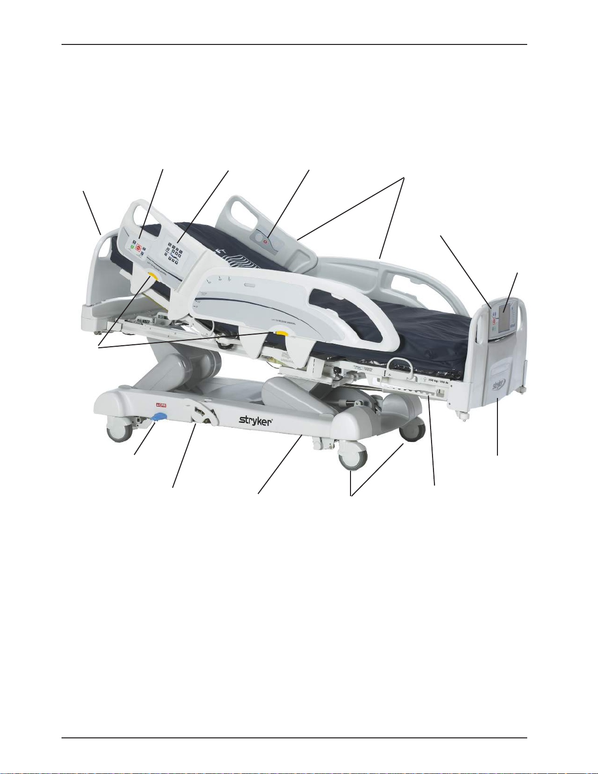
PRODUCT ILLUSTRATION
Introduction
Headboard
Siderail
Release
Levers
Brake Control
Panel
Nurse Control
Panel
Nurse Call
Siderails
Footboard
Control Panel
InTouch®
Screen
CPR Emergency
Release Pedal
Manual
Backup
Return To Table of Contents
10 2131-509- 002 RE V B www.stryker.com
®
Drive Wheel
Zoom
(Model 2141 only)
(Under base -
not shown)
Casters
Foley Bag
Hooks
Footboard
Page 11

SPECIFICATIONS
Safe Working Load
Introduction
Note: Safe Working Load indicates the
sum of the patient, mattress and accessory
weight.
Bed Weight 750 lbs 340.2 kg
Overall Bed Length 90” 228,6 cm
Overall Bed
Width
Base Underbed Clearance 5” 12,7 cm
Litter Patient Surface
Fowler Length 36.5” 92,7 cm
Bed Lift
System
Scale System Capacity 550 lbs 249 kg
Siderails Up 42” 106,7 c m
Siderails Down 40” 102,9 cm
• Width
• Length
• Length (with Optional Bed
Extender)
Seat Section
• Depth
Foot Section
• Length
• Angle
Fowler Section
• Length
• Width
• Angle
Gatch Section
• Length
• Width
• Angle
Cardiac Chair
• Standard Cardiac Chair Position
• Enhanced Cardiac Chair Position
Height (high) to top of litter 33” 83,8 cm
Height (low) to top of litter 16” 40,6 cm
Trendelenburg/Reverse Trendelenburg 12°
Bed Lift Time 35 seconds maximum from lowest to highest position
Accuracy:
• For weight from 100 lb to 550 lb
• For weight from 100 lb to 550 lb
• For weight under 100 lb
• For weight under 100 lb
550 lbs 249 kg
35”
84”
90”
18.5” 47 cm
29”
0° to 50°
36”
34” to 35”
0° to 70°
18”
34” to 35”
0° to 15°
Head: 65°, Seat: 17°, Foot: 30°, Trend: 3°
Head: 70°, Seat: 19°, Foot: 47°, Trend: 3°
+/- 2% when in Trendelenburg or Reverse Trendelenburg
+/- 2% when Flat
+/- 2 lb when in Trendelenburg or Reverse Trendelenburg
+/- 2 lb when Flat
88,9 cm
213,4 cm
228,6 cm
73,7 cm
0° to 50°
91,4 c m
86,4 cm - 88,9 cm
0° to 70°
45,7 cm
86,4 cm - 88,9 cm
0° to 15°
CPR System Speed to level bed from any position
• Fowler
• Foot and Seat
Drive System Speed (Optional Zoom® Drive)
• Forward
• Backwards
www.stryker.com 2131-509- 002 RE V B 11
15 seconds
60 seconds
3.6 mph
2.5 mph
5.8 km/h
4.0 km/h
Return To Table of Contents
Page 12

SPECIFICATIONS (CONTINUED)
Introduction
Mattress
Maximum
Current
Consumption
Environmental
Conditions
Electrical
Requirements
Battery
Recommended Mattress Size
•With Bed Extender DM64196
(PositionPRO) (35” x 6” x 4”)
•With Bed Extender DM64197
(XPRT™) (35” x 6” x 5.5”)
Recommended Air Mattress Size
•With Bed Extender DM64196
(PositionPRO) (35” x 6” x 4”)
•With Bed Extender DM64197
(XPRT™) (35” x 6” x 5.5”)
Without Optional Auxiliary Outlet
(120VAC O nly )
With Optional Auxiliary Outlet(s)
(120VAC O nly )
Storage
• Ambient Temperature
• Relative Humidity
• Atmospheric Pressure
Operating
• Ambient Temperature
• Relative Humidity
• Atmospheric Pressure
• Scale Accuracy
All electrical requirements meet CSA
C22.2 No. 601.1, UL 60601-1 and IEC
60601-1.60601-2-38 specifications.
12 V, 17.6 Ahr, Sealed Lead-Acid Battery (Part Number QDF9188)
3.0 V 220mAh Lithium Battery, Size 20mm - Varta Int. CR2032
Coin Cell PC Battery Holder, Size 20mm - MDP Int. BA2032
35” x 84” x 6” 88,9 cm x 213,4 cm x 15,2 cm
35” x 90” x 4” 88,9 cm x 228,6 cm x 10,1 cm
35” x 90” x 5.5” 88,9 cm x 228,6 cm x 13,9 cm
35” x 84” x 6” - 8.5”
35” x 90” x 4” 88,9 cm x 228,6 cm x 10,1 cm
35” x 90” x 5.5” 88,9 cm x 228,6 cm x 13,9 cm
4.8 Amps
9.8 Amps
-40°F to 158°F
10 to 100%
500 to 1060 hPa
50°F to 104°F
30 to 75%
700 to 1060 hPa
18 °C to 25 °C
100V~, 50-60Hz, 7.5A - Two 250V, 10A Fuses
120 ± 10% Vac, 50/60Hz - Two 250V, 10A Fuses
120V~, 50-60Hz, 4.0A (9.8A with 120V Optional Auxiliary
Outlet) - Two 250V, 10A Fuses
200V~, 50-60Hz, 3.2A -Two 250V, 10A Fuses
220V~, 50-60Hz, 2.9A -Two 250V, 10A Fuses
240V~, 50-60Hz, 2.7A -Two 250V, 10A Fuses
88,9 cm x 213,4 cm x
15,2 cm - 21,6 cm
-40°C to 70°C
10°C to 40°C
64 °F to 77 °F
Stryker reserves the right to change specifications without notice.
Specifications listed are approximate and may vary slightly from unit to unit or by power supply fluctuations.
Return To Table of Contents
12 2131-509- 002 REV B www.stryker.com
Page 13

Summary of Safety Precautions
Before operating the bed, it is important to read and understand all information in this manual. Carefully read and
strictly follow the safety guidelines listed below.
Note
To ensure safe operations of the bed, methods and procedures must be established for educating and training hospital
staff on the intrinsic risks associated with the usage of electric beds.
WARNING
• To prevent permanent damage to this unit, the unit must reach room temperature prior to conducting any setup
and/or unit operations.
• The Weigh system is intended to assist in the monitoring of the patient’s weight variation. Under no circumstances
should its reading be used as sole reference for medical treatment.
• Preventative maintenance should be performed at least once a year to ensure all bed features are functioning
properly.
• This bed is not intended for pediatric use, i.e., for any patient measuring 35 inches (88,9 cm) or less.
• This bed is equipped with a hospital grade plug for protection against shock hazard. It must be plugged directly into
a properly grounded receptacle. Grounding reliability can be achieved only when a hospital grade receptacle is used.
• Shock Hazard - Improper handling of the power cord may result in damage to the power cord and potential shock
hazards. If damage has occurred to the power cord, immediately remove the bed from service and contact the
appropriate maintenance personnel. Failure to do so could result in serious injury or death.
• Serious injury can result if caution is not used when operating the bed. Operate the bed only when all people and
equipment are clear of the electrical and mechanical systems.
• Always apply the brakes when a patient is on the bed or entering/exiting the bed. Serious injury could result if the bed
moves while a patient is getting on or off the bed. Once the brake pedal is engaged, push on the bed to ensure the
brakes are securely applied. Do the same test when using the electrical brake.
• To help reduce the number and severity of a potential fall when the patient is unattended, keep the siderails in the
fully raised position and the sleep surface horizontal in its lowest position, unless his/her medical condition dictates
otherwise. When raising the siderails, be sure that you hear the “click” that signals the locked condition. Pull firmly
on the siderail to ensure it is locked into position.
• When the sleep surface sections are articulated, ensure that all the patient’s limbs are within the raised siderails to
avoid patient injury.
• When a patient’s condition requires greater safety measures for his/her security, use the lockout controls in the
footboard control panel to inhibit the siderail functions or remove any optional pendant control and install protective
pads on the siderails.
• Siderails, with or without their padded covers, are not intended to serve as restraint devices to keep a patient from
exiting the bed. Siderails are designed to keep a patient from inadvertently rolling off the bed. It is the responsibility of
the attending medical personnel to determine the degree of restraint necessary to ensure a patient will remain safely
in bed. Failure to use the siderails properly could result in serious patient injury.
• To reduce the risk of injury, ensure the sleep surface is horizontal and in the lowest position with the siderails fully
raised and locked when moving the bed with a patient in it.
• To avoid injury to the patient and/or user, do not attempt to move the bed laterally with the steer mode engaged. The
steer wheel cannot swivel.
• The CPR emergency pedal is for emergency use only. When activating the CPR pedal, all people and equipment must
be removed from the area below and around the head, thigh and foot sections of the bed or serious personal injury
and/or equipment damage could occur.
• To stop the fowler from moving down, the CPR pedal can be released at anytime during activation.
• The manual backup brake is for emergency use only. It should not be used for any other situation than an emergency
or it might get overused when the time comes to use it for an emergency.
• Possible fire hazard exists when this bed is used with oxygen administering equipment other than nasal, mask type
or half bed-length tent type. Unplug the bed power cord from the wall when oxygen administering equipment is used.
• When using a half bed-length tent type, ensure that the siderails are outside the oxygen tent and that the tent does
not extend below the mattress support level. Do not route the power cord between the mattress and the bed frame.
• Do not attach the power cord to any moving parts of the bed frame.
• The power cord could be pinched and may cause electrical shock if a bed extender is used.
• The Bed Exit system is not designed to be used with patients weighing less than 50 lbs (23 kg).
Return To Table of Contents
www.stryker.com 2131-509- 002 RE V B 13
Page 14

Summary of Safety Precautions
WARNING (CONTINUED)
• The Bed Exit system is intended only to aid in the detection of a patient exiting the bed. It is not intended to replace
patient monitoring protocol. The Bed Exit system signals when a patient is about to exit the bed. The addition or
removal of equipment with the Bed Exit system armed must be done using the “Adding or Removing Equipment
with the System Armed” procedure, otherwise the sensitivity of the system may be affected and the readings of the
patient’s movements in the bed may be erroneous.
• Do not steam clean, hose off or ultrasonically clean the bed. Do not immerse any part of the bed. The internal
electrical parts may be damaged by exposure to water. Hand wash regularly all surfaces of the bed with warm water
and a mild detergent. Wipe cleaned surfaces dry to avoid build-up of cleaning substances. Inspect the mattress
after each use. Discontinue use if any cracks or rips, which may allow fluid to enter the mattress, are found in the
mattress cover. Failure to properly clean the mattress, or dispose of it if defective, may increase the risk of exposure
to pathogenic substances and may bring about diseases to the patient and user.
• Always unplug the bed power cord from the wall socket when servicing or cleaning the bed. When working under the
bed with the bed in the high position, always apply the brakes and place blocks under the Bed Lift levers to prevent
injury in case the Bed Down switch is accidentally pressed.
• Please ensure patient is not in the bed prior to starting bed calibration. In calibration mode, the software does
not control the interferences between the mechanical parts of the bed. Mechanical damage could occur without
supervision. Only qualified personnel should perform the calibration.
• Battery posts, terminals and related accessories contain lead and lead compounds - chemicals known to the state
of California to cause cancer and birth defects or other reproductive harm. Wash hands after handling.
• Do not modify the InTouch® bed. Modifying the unit can cause unpredictable operation resulting in injury to the
patient or user. Modifying the unit will also void this warranty.
CAUTION
• When using a mattress thicker than 6 inches (15,24 cm) or a mattress overlay, extra caution and/or patient supervision
may be required to reduce the likelihood of occurrence of a patient fall.
• Preventative maintenance should be performed at least once a year to ensure all bed features are functioning
properly. Ensure that any bed malfunction is promptly reported to your service personnel for immediate attention.
• When large fluid spills occur in the area of the circuit boards, cables and motors, immediately unplug the bed power
cord from the wall socket, remove the patient from the bed and clean up the fluid. Have maintenance completely
check the bed. Fluids can have an adverse effect on operational capabilities of any electrical product. DO NOT
put the bed back into service until it is completely dried and has been thoroughly tested for safe operation. Ensure,
among other things, that the plastic components being used as covers for the siderail mechanism arms and the foot
end casing are removed and that the parts they cover are thoroughly dried.
• To avoid damage to the siderail mechanisms, do not move the bed using the raised siderails. Move the bed using the
handles integrated to the boards.
• Because individual beds may have different options, footboards should not be moved from one bed to another.
Mixing footboards could result in unpredictable bed operation.
• The mattress thickness should not exceed 6 inches (15,24 cm).
• When servicing, use only identical replacement parts provided by Stryker.
• SOME CLEANING PRODUCTS ARE CORROSIVE IN NATURE AND MAY CAUSE DAMAGE TO THE PRODUCT IF
USED IMPROPERLY. If the products described above are used to clean Stryker patient care equipment, measures
must be taken to ensure the beds are wiped with a damp cloth soaked in clean water and thoroughly dried following
cleaning. Failure to properly rinse and dry the beds will leave a corrosive residue on the surface of the bed, possibly
causing premature corrosion of critical components. Failure to follow the above directions when using these types
of cleaners may void this product’s warranty.
Note
• Throughout this Operations Manual, the words “right” and “left” refer to the right and left sides of a patient lying on
his/her back on the bed.
• The addition of accessories affects the motion of the bed.
• The iBed option is only used as an informational feature and is not supposed to replace normal patient monitoring
protocol.
Return To Table of Contents
14 2131-509-002 REV B ww w.stryker.com
Page 15

Summary of Safety Precautions
OPTIONAL ZOOM® DRIVE SYSTEM (MODEL 2141)
In addition to the previous warnings and cautions, all of the following warnings and cautions apply to units equipped
with the Zoom®.
WARNING
• The 2141 InTouch® Bed is intended for use by trained hospital personnel only. Failure to properly train personnel
could result in injury.
• USE CAUTION while maneuvering the unit with the drive wheel activated. Always ensure there are no obstacles
near the unit while the drive wheel is activated. Injury to the patient, user or bystanders or damage to the frame or
surrounding equipment could occur if the unit collides with an obstacle.
• Use caution when transporting the unit down halls, through doors, in and out of elevators, etc. Damage to the
siderails or other parts of the unit could occur if the unit comes in contact with walls or door frames.
• Put the drive wheel in the neutral position and release the brake before pushing the unit manually. For 2141 models;
push the Brake Off button to disengage drive wheel (Zoom®) before pushing the unit manually. Do not attempt
to push the unit manually with the drive wheel engaged. The unit will be difficult to push and injury could result.
• If unanticipated motion occurs, unplug the power cord from the wall socket, push the battery power on/off switch
to the “OFF” (0) position (the LED will not be illuminated), actuate the drive wheel pedal to the neutral position
and call maintenance.
• The power save mode is activated after one hour on battery power with no motion release switch activation.
Functions including Bed Exit, Scale and Motion will cease to operate when the unit enters the power save mode.
Injury to the patient could occur if proper patient monitoring protocol is not observed.
• Always unplug the power cord and push the battery power on/off switch to the “OFF” (0) position before service
or cleaning. When working under the frame, always support the litter frame to prevent injury in case the Bed Down
switch is accidently activated.
Return To Table of Contents
www.stryker.com 2131-509- 002 RE V B 15
Page 16
Static Discharge Precautions
The electronic circuits in the InTouch® Critical Care Bed are completely protected from static electricity damage only
while the bed is assembled. It is extremely important that all service personnel always use adequate static protection
when servicing the electronic systems of the InTouch® Critical Care Bed. You should be using static protection
whenever you are touching wires.
Static Protection Equipment
The necessary equipment for proper static protection is:
• 1 static wrist; 3M part number 2214 or equivalent,
• 1 grounding plug; 3M part number 61038 or equivalent,
• 1 test lead with a banana plug on one end and an alligator clip on the other; Smith part number N132B699 or
equivalent.
CAUTION
All electronic service parts will be shipped in static shielding bags. Do not open the bags until you have completed steps
2 and 3 of the following procedure. Do not place unprotected circuit boards on the floor. All circuit boards to be returned
to Stryker Medical should be shipped in the static shielding bags the new boards were shipped in.
Static Protection Procedure
1. Unplug the power cord from the power source.
2. Insert the grounding plug into a properly grounded hospital grade wall receptacle. Plug the banana plug of the
test lead into the receptacle on the grounding plug. Connect the alligator clip on the other end of the test lead to
a ground point on the bed.
3. Place the static control wrist strap on your wrist. Connect the alligator clip at the other end of the wrist strap cord
to a ground point on the bed.
BED
GROUNDING DIAGRAM
Return To Table of Contents
16 2131-50 9- 002 RE V B www.stryker.com
Page 17

Setup Procedures
To prevent permanent damage to this unit, the unit must reach room temperature prior to conducting any setup
and/or unit operations.
It is important to ensure that the bed is working properly before it is put into service. The following list will help
ensure that each part of the bed is checked.
• Install the foot and head boards on the bed. Insert the footboard carefully so that the footboard and the casing
connectors fit in smoothly.
CAUTION
Because individual beds may have different options, footboards should not be moved from one bed to another. Mixing
footboards could result in unpredictable bed operation.
• Plug the power cord to the bed connector at the head end of the bed and into a properly grounded hospital grade
wall outlet.
• Turn the battery power switch to the “ON” (1) position (located below the litter surface at patient right side).
• Set the time and date through the touch screen (refer to the InTouch® Operations Manual for procedures).
WARNING
This bed is equipped with a hospital grade plug for protection against shock hazard. It must be plugged directly into a
properly grounded receptacle. Grounding reliability can be achieved only when a hospital grade receptacle is used.
• To test the manual backup brake (located on the patient’s right side only), flip the manual backup brake pedal
outward and depress down fully on the foot end side of the pedal. The word BRAKE in red will be visible in the
clear window located on the base next to the pedal and the Brake symbol will be flashing on the footboard control
panel. The brakes should now be applied.
• To test the electric brake; engage the brake by pressing the brake button on the siderail or footboard control panel.
Try moving the bed to ensure the brakes are applied. Press the Neutral or Brake button on the siderail control panel
or on the footboard to disengage the brake.
• For Model 2141 Beds only: On the patient’s right side, flip the manual backup brake pedal outward and depress
down fully on the head side of the pedal. The letter D in GREEN should be visible in the clear window located on
the base next to the pedal. The Zoom® Drive wheel should now be engaged. Depress down fully on the center
of the pedal until the letter N in BLUE is visible in the clear window. The Zoom® Drive wheel should now be
disengaged.
• Ensure that the siderails raise, lock in the fully raised position and lower smoothly.
• Run through each control on the footboard.
• Verify the scale system and the Bed Exit system for proper operation.
• Run through each control on both inner and outer control panels of the head siderails. If the bed is equipped with
the optional Siderail Communication Pendant, plug the provided cable to the 37-pin connector located at the head
end of the bed and into the proper wall outlet.
• Raise the bed completely and activate the Trendelenburg function. Ensure the head end lowers to the full down
position (refer to the InTouch® Operations Manual for procedures). Level the bed using the Bed Lift system
controls.
• Raise the bed completely and activate the reverse Trendelenburg function. Ensure the foot end lowers to the full
down position (refer to the InTouch® Operations Manual for procedures). Level the bed using the Bed Lift system
controls.
• Verify functionality of the CPR emergency release: raise the fowler up then depress down on the CPR pedal
located on either side of the bed at the head end of the base. The fowler will lower towards a flat position until
the pedal is released.
• Ensure the Knee Gatch (if raised) also starts flattening when the Fowler is completely down. Following the
complete lowering of the Fowler, wait approximately 30 seconds (the time for the Fowler control motor to reset)
and verify that the motor has indeed reset by raising the Fowler fully up using the “Fowler Up” control.
• Verify the following optional equipment for proper operation: 120V Auxiliary Outlet, Head End Nurse Controls,
Pendant, Roller Bumpers, Zoom® Handles, etc.
• To prevent permanent damage to the bed, ensure the unit reaches room temperature prior to use.
Return To Table of Contents
www.stryker.com 2131-509- 002 RE V B 17
Page 18

Setup Procedures
OPTIONAL XPRT™ THERAPY MATTRESS
If your bed is equipped with the XPRT™ Therapy Mattress option, perform the following setup procedures to install
the Mattress. For graphic representation of the setup procedures, refer to the XPRT™ Therapy Mattress Operations
Manual.
CAUTION
When using a mattress thicker than 6 inches (15,24 cm) or a mattress overlay, extra caution and/or patient supervision
may be required to reduce the likelihood of occurrence of a patient fall.
1. Place mattress over bed litter with printed logo at head end of the bed.
2. Fold back foot end section of mattress.
3. Place foot box on foot end of bed litter.
4. Connect the two (2) color coded connectors on the foot box to the corresponding color coded connectors on the
mattress. Connect black connection on foot box to cable adapter 2950-001-180 and then to the bed frame.
5. Turn the locking collars clockwise to secure the connections.
6. Connect the other end of the black connector to the bed (left side of litter at foot end behind the accessory outlet).
7. Connect the air line from the mattress to the corresponding fitting on the foot box.
8. Fasten the two (2) retaining clips to the two (2) D-Rings on the foot box.
9. Lower the foot section of mattress over the foot box. Attach the mattress to the bed frame using the mattress
tie-downs.
10. Apply linens utilizing the “D” rings for the flat sheet.
11. To secure linens, to mattress, thread four corners through D-Rings attached to mattress.
12. To ensure proper therapy, do not pull linens taut. The linens should remain loose and wrinkly on the surface of
the mattress.
13. Plug the mattress power cord into a properly grounded, hospital grade receptacle.
Note
The InTouch® bed will detect when the mattress has been connected as well as what type of mattress it is. This will
be shown on the InTouch® screen.
WARNING
• Do not route the power cord between the mattress and the bed frame.
• Do not attach the power cord to any moving parts of the bed frame.
• The power cord could be pinched and may cause electrical shock if a bed extender is used.
OPTIONAL POSITIONPRO™ REPOSITIONING MATTRESS OPTION
If your bed is equipped with the PositionPRO™ Patient Repositioning Mattress option, perform the following setup
procedures to install the mattress. For graphic representation of the setup procedures, refer to the PositionPRO™
Mattress Operations Manual.
CAUTION
When using a mattress thicker than 6 inches (15,24 cm) or a mattress overlay, extra caution and/or patient supervision
may be required to reduce the likelihood of occurrence of a patient fall.
1. Place the mattress onto the bed.
2. Flip the foot section towards the head end.
3. Place the control box (upside down) into the opening in the foot section.
4. Connect outer transparent tubes to manifold, matching the color coding.
Return To Table of Contents
18 2131-50 9- 002 RE V B www.stryker.com
Page 19

Setup Procedures
OPTIONAL POSITIONPRO™ REPOSITIONING MATTRESS (CONTINUED)
5. Connect tilt sensor cables.
a. Align the white dots.
b. Twist clockwise to fasten.
6. Connect pendant cable.
7. Connect power cord (4’) and turn the switch to on.
Note: The switch is hidden under the power cord.
8. Fasten straps over the power cord.
9. Install the power cord in the two (2) retaining clips.
10. Fasten the three (3) retaining straps.
11. Carefully rotate the foot end control box and the mattress into the flat position.
CAUTION
Gently lower the foot end section to not damage the control box.
12. Fasten the retaining straps to secure the mattress to the bed frame (four (4) straps total).
13. Connect the power cord to the 110V outlet on the bed.
Applying the linens
1. Apply the linens using the “D” rings for the flat sheet.
2. To effectively use the “Turn Assist”, do not pull linens taut. Linens should remain loose and wrinkly on surface of
the mattress.
WARNING
Ensure that you have always access to the CPR straps.
Note
If any problems are found during bed setup, contact our Technical Service department at USA: 1-800-327-0770 (option
2).
OPTIONAL ZOOM® DRIVE SYSTEM (MODEL 2141)
If your bed is equipped with the Zoom® drive, run through the preceding setup procedures and continue with the
procedures listed below.
• With the battery power switch in the “ON” (1) position and the drive wheel in the neutral position (not touching the
floor), ensure the “Engage Drive Wheel” LED on the head end control panel is illuminated.
• Run through the operation of the drive wheel (refer to InTouch® Operations Manual for procedures) to ensure it
is operating properly.
• On both sides of the bed, flip the manual backup brake pedal outward and depress down fully on the head side of
the pedal. The letter D in GREEN should be visible in the clear window located on the base next to the pedal. The
Zoom® drive (2141 Model only) should now be engaged. Depress down fully on the center of the pedal until the
letter N in BLUE is visible in the clear window. The Zoom® drive should now be disengaged.
Return To Table of Contents
www.stryker.com 2131-509- 002 RE V B 19
Page 20

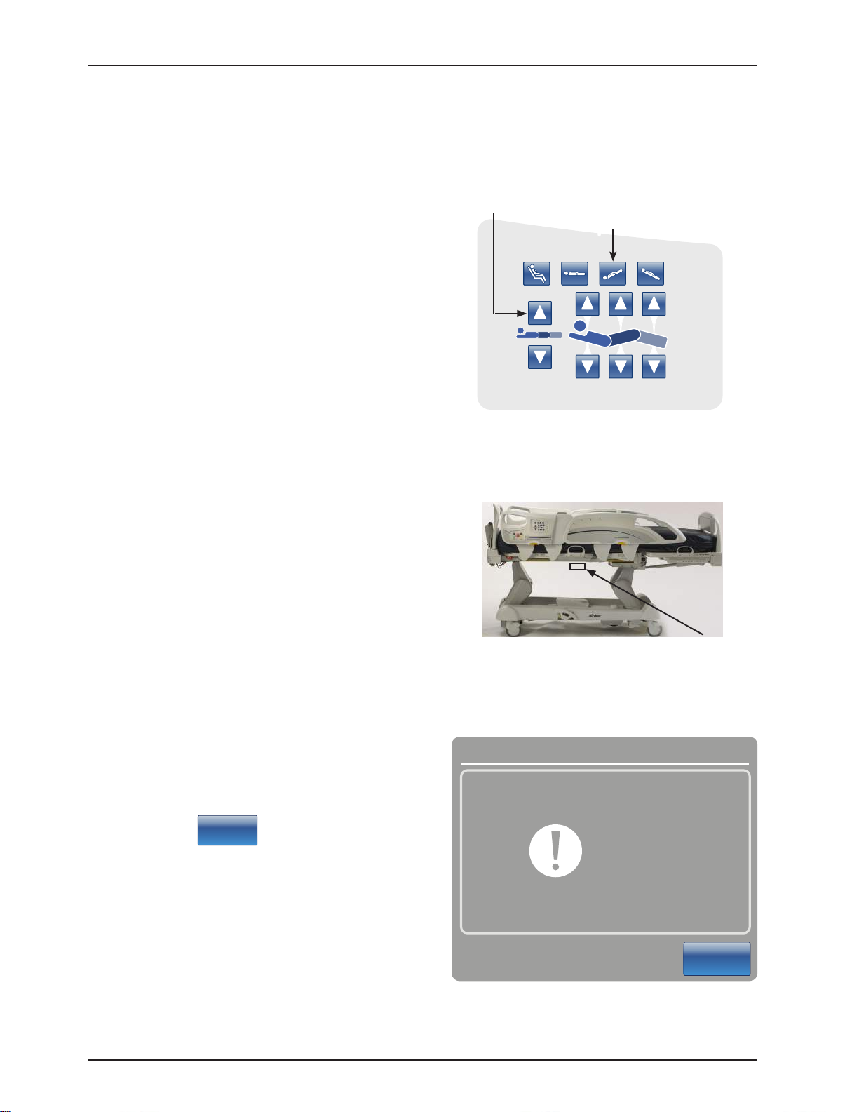
Maintenance Menu Guide
The Maintenance Menu is accessed through the Touch Screen and contains additional features of the product. This
menu provides an interface to the user and/or service personnel in order to provide the ability to control and access
maintenance features.
ACCESSING CONFIGURATION SCREEN
WARNING
Please ensure patient is not in the bed prior to starting bed calibration. In calibration mode, the software does
not control the interferences between the mechanical parts of the bed. Mechanical damage could occur without
supervision. Only qualied personnel should perform the calibration.
Note
Verify that the bed is on a level surface which does not have any slopes or inclines prior to entering into the
calibration mode.
1. Unseat and reseat the footboard and wait until the main control screen is displayed.
2. Push and hold the Main Menu button located in the upper right corner of the footboard control panel
(see Figure 1 below). Continue pressing on the Main Menu button while executing steps 3-5.
3. Push and hold the Brake button for 8-10 seconds and then release.
4. Push the HOB 30o+ button once and release.
5. Push the Drive button once and release.
6. Release the Main Menu button and you will be taken into the Conguration Screen shown in Figure 2.
HOB
Brake
Main Menu
Drive
Figure 1: Footboard Control Panel
Figure 2: Conguration Screen
Return To Table of Contents
20 2131-509-002 REV B www.stryker.com
Page 21

Maintenance Menu Guide
CONFIGURATION SCREEN
The following items A, B, and C are configuration buttons
available and displayed on the Configuration screen
(Figure 3).
A. Bed Calibration
B. Full Diagnostic (see page 32)
C. Touch Screen Calibration (see page 33)
The following items D and E are configuration options
available but are not displayed on the Configuration
screen To access these configuration options, follow the
procedures identified on page listed below.
D. Bed Options Configuration (see page 34)
E. Serial Number Configuration (see page 35)
Figure 3: Configuration Screen Menu Items
A. Bed Calibration
Note: During calibration, if the backlight shuts off touch the screen to continue.
WARNING
Refer to Figure 4 for WARNING details.
1. To start the bed calibration, press the Bed Calibration button on the Configuration Screen (refer to Figure 3).
2. After pressing the Bed Calibration button, Figure 4 will be displayed. Press “NEXT” to continue with
calibration.
Figure 4: Bed Calibration - WARNING
Return To Table of Contents
www.stryker.com 2131-509- 002 RE V B 21
Page 22

Maintenance Menu Guide
CONFIGURATION SCREEN (CONTINUED)
A. Bed Calibration (Continued)
3. After pressing “NEXT” to continue calibration,
Figure 5 will appear.
Figure 5: Bed Calibration - Step #1 of 6
4. Place the Litter surface to a flat position
by pressing simultaneously the Foot Up,
Fowler Down and Gatch Down buttons as
shown in Figure 6.
5. Lower the bed to the lowest position. Press
the Bed Height Down (Head Lift Down) and
Reverse Trendelenburg (Foot Lift Down)
buttons simultaneously as shown in Figure 7.
Foot Up
QDF27-2237
Fowler Down
Gatch Down
Figure 6: HE Siderail Control Panel - (Right Side Shown)
Reverse Trendelenburg
(Foot Lift Down)
Bed Height
Down
(Head Lift
Down)
QDF27-2237
Figure 7: HE Siderail Control Panel - (Right Side Shown)
Return To Table of Contents
22 2131-50 9- 002 RE V B www.stryker.com
Page 23

Maintenance Menu Guide
CONFIGURATION SCREEN (CONTINUED)
A. Bed Calibration (Continued)
Bed Calibration
Do Not
Touch Bed
6. Press the
Next
button when done. The “Do
Not Touch Bed” screen will appear as shown in
Figure 8.
Cancel
Figure 8
7. When step 1 of the calibration procedure has completed, step 2 of the calibration procedure will begin and
Figure 9 will be displayed as shown below.
Figure 9: Bed Calibration - Step 2
Return To Table of Contents
www.stryker.com 2131-509- 002 RE V B 23
Page 24
Maintenance Menu Guide
CONFIGURATION SCREEN (CONTINUED)
A. Bed Calibration (Continued)
8. Raise the bed height to 20 inches measuring
from the top of the seat section to the floor.
Press the Bed Height Up (Head Lift Up) and
Trendelenburg (Foot Lift Up) buttons as
shown in Figure 10.
9. Standing on either side of the bed at the fowler
section, raise the foot siderail and then position
the digital level/inclinometer on the bottom of
the litter below the mattress retainer (refer to
Figure 11). Using the digital level/inclinometer,
verify the bed is level (0.0 +/- 0.2).
Bed Height Up
(Head Lift Up)
Trendelenburg
(Foot Lift Up)
Figure 10: Head Siderail Control Panel
(Right Side Shown)
QDF27-2237
Note: Cycle power on the digital level/
inclinometer prior to placing it on the
bottom of the litter frame and do not zero/
calibrate the digital level/inclinometer.
10. Press the
Next
button when done. The
“Do Not Touch Bed” screen will appear as
shown in Figure 12.
Placement
on Litter
Figure 11: Inclinometer placement
Bed Calibration
Do Not
Touch Bed
Cancel
Figure 12: Do Not Touch Bed Screen
Return To Table of Contents
24 2131-509- 002 RE V B w ww.stryker.com
Page 25
Maintenance Menu Guide
CONFIGURATION SCREEN (CONTINUED)
A. Bed Calibration (Continued)
11. When step 2 of the calibration procedure has completed, step 3 of the calibration procedure will begin and
Figure 13 as shown below will appear on the screen.
Figure 13: Bed Calibration - Step 3
12. Place the bed at +12 degrees Trendelenburg by pressing
the Trendelenburg (Foot Lift Up) button as shown in
Figure 14. Verify +12 degrees +/- 0.1 with the inclinometer
you previously placed on the litter frame in step 9.
Trendelenburg
(Foot Lift Up)
QDF27-2237
Figure 14: Head Siderail Control Panel
Return To Table of Contents
www.stryker.com 2131-509- 002 RE V B 25
Page 26

Maintenance Menu Guide
CONFIGURATION SCREEN (CONTINUED)
A. Bed Calibration (Continued)
Bed Calibration
13. Press the
Next
button when done.
Do Not
Touch Bed
14. The “Do Not Touch Bed” screen will appear as
shown in Figure 15.
Cancel
Figure 15: Do Not Touch Bed Screen
15. When step 3 of the calibration procedure has completed, step 4 of the calibration procedure will begin and
Figure 16 will be displayed as shown below.
Figure 16: Bed Calibration - Step 4
Return To Table of Contents
26 2131-50 9- 002 REV B www.stryker.com
Page 27
Maintenance Menu Guide
CONFIGURATION SCREEN (CONTINUED)
A. Bed Calibration (Continued)
16. Level the bed back out to zero degrees by pushing
the Reverse Trendelenburg button until the litter
is level while referencing the inclinometer. Note:
Confirm inclinometer reads zero degrees.
17. Place the bed at -12 degrees Reverse Trendelenburg
by pressing the Bed Height Up (Head Lift Up) button
as shown in Figure 17 below. Verify -12 degrees +/-
0.1 with the inclinometer you previously placed on the
bottom of the litter frame in step 9.
18. Press the
19. The “Do Not Touch Bed” screen will appear as
shown in Figure 18.
Next
button when done.
Bed Height Up
(Head Lift Up)
QDF27-2237
Figure 17: Head Siderail Control Panel -
(Right Side Shown)
Bed Calibration
Do Not
Touch Bed
Cancel
Figure 18: Do Not Touch Bed Screen
Return To Table of Contents
www.stryker.com 2131-509- 002 RE V B 27
Page 28
Maintenance Menu Guide
CONFIGURATION SCREEN (CONTINUED)
A. Bed Calibration (Continued)
20. When step 4 of the calibration procedure has completed, step 5 of the calibration procedure will begin and
Figure 19 will appear on the screen as shown below.
Figure 19: Bed Calibration - Step 5
21. Place the bed at the highest height by pressing
simultaneously the Trendelenburg (Foot Lift Up)
button and Bed Height Up (Head Lift Up) button as
shown in Figure 20.
Trendelenburg
(Foot Lift Up)
Bed Height Up
(Head Lift Up)
QDF27-2237
Figure 20: Head Siderail Control Panel -
(Right Side Shown)
Return To Table of Contents
28 2131-509- 002 REV B www.stryker.com
Page 29
Maintenance Menu Guide
CONFIGURATION SCREEN (CONTINUED)
A. Bed Calibration (Continued)
Gatch Up
22. Press the Fowler Up button until the Fowler reaches
the highest height, next press the Gatch Up button
until the Gatch reaches its highest height, lastly
press the Foot Up button until the foot section
reaches its highest height (refer to Figure 21
below). The foot section should be at a flat position.
23. Press the
Next
button when done.
24. The “Do Not Touch Bed” screen will appear as
shown in Figure 22.
Fowler Up
Figure 21: Head Siderail Control Panel -
(Right Side Shown)
Bed Calibration
Do Not
Touch Bed
Foot Up
QDF27-2237
Cancel
Figure 22: Do Not Touch Bed Screen
Return To Table of Contents
www.stryker.com 2131-509- 002 RE V B 29
Page 30
Maintenance Menu Guide
CONFIGURATION SCREEN (CONTINUED)
A. Bed Calibration (Continued)
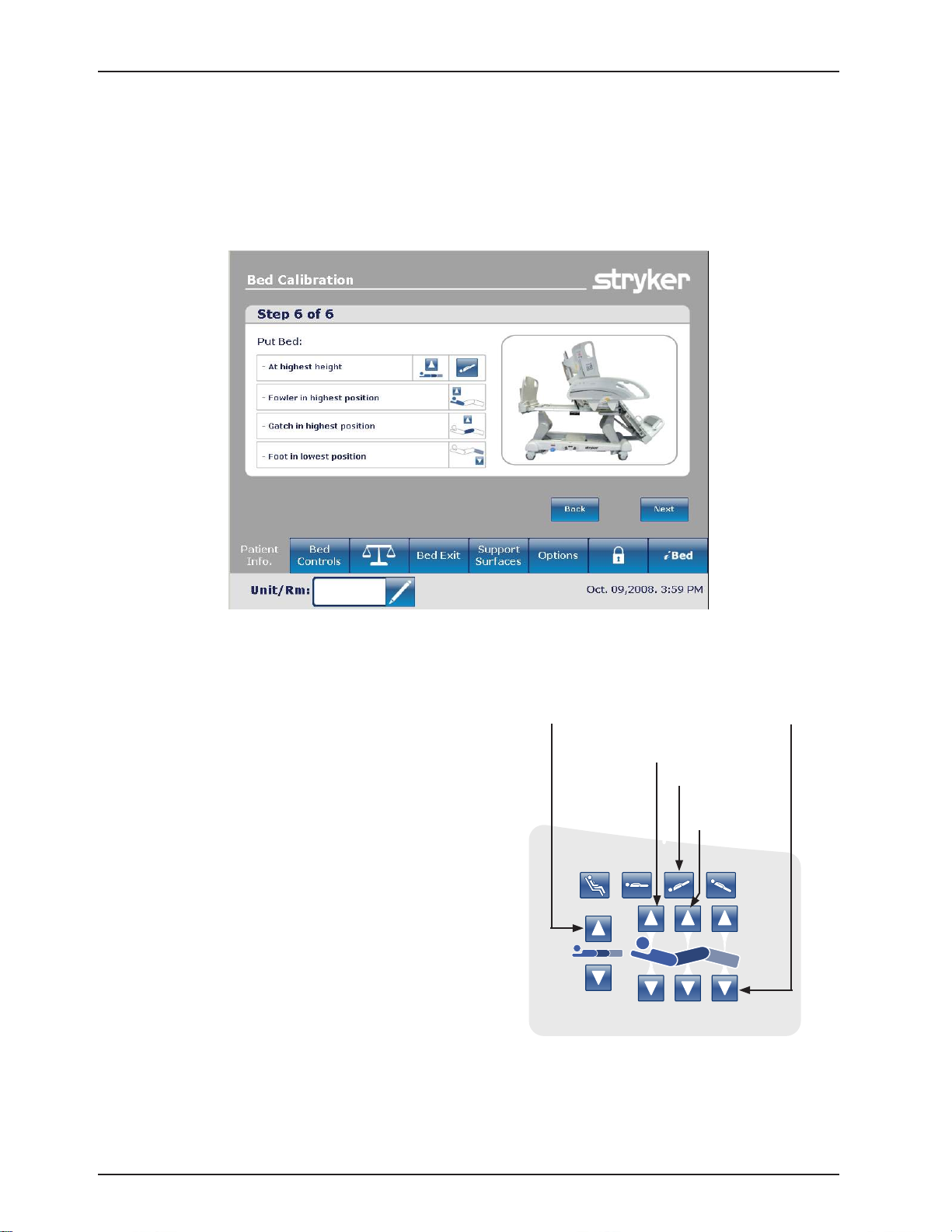
25. When step 5 of the calibration procedure has completed, step 6 of the calibration procedure will begin and
Figure 23 will be displayed as shown below.
Figure 23: Bed Calibration - Step 6
26. Place the bed at the highest height by pressing
simultaneously the Trendelenburg (Foot Lift Up)
button and Bed Height Up (Head Lift Up) button (see
Figure 24).
27. Place the Fowler and Gatch section of the bed at the
highest height by first pressing the Fowler Up button
then the Gatch Up button (See Figure 24).
28. Place the foot at the lowest position by pushing the
Foot Down button until limit is met (see Figure 24) .
CAUTION: The Gatch must be raised to the highest
height prior to running the Foot Down or damage
could occur.
Bed Height Up
(Head Lift Up)
Fowler Up
Trendelenburg
(Foot Lift Up)
Gatch Up
Figure 24: Calibration Complete
Foot Down
QDF27-2237
Return To Table of Contents
30 2131-509-002 REV B w ww.stryker.com
Page 31

Maintenance Menu Guide
CONFIGURATION SCREEN (CONTINUED)
A. Bed Calibration (Continued)
29. When the calibration procedure is completed, Figure 25 will be displayed as shown below.
30. Press the Close button to exit the Calibration Procedure Menu.
31. Level the litter flat using the CPR pedal. Verify all display readings are zero degrees while the bed is at
33” (84 cm) (highest height). Lower the bed to 16” (41 cm) (lowest height) and verify the display readings
maintain a constant reading of zero degrees with no fluctuations. When the bed reaches it lowest height
at 16”, verify the display readings are still at zero degrees.
Note: If readings are not all zero, you will need to recalibrate the bed by repeating steps 1-30.
Figure 25: Calibration Complete
Return To Table of Contents
www.stryker.com 2131-509- 002 RE V B 31
Page 32

Maintenance Menu Guide
CONFIGURATION SCREEN (CONTINUED)
B. Full Diagnostic
1. From the Configuration Screen, press the
Full Diagnostic button. Figure 26 will appear.
2. The following menu items may be selected
by pressing their button.
a. BOARDS (Figure 27a)
Provides information on the switch
boards and the touch screen’s
software version.
b. ERROR CODES (Figure 27b)
Provides information on errors which
the CPU board has identified.
c. IN PUT STAT ES (Figure 27c)
Provides information on the status of
all switches and jumpers on the bed.
d. MOTORS (Figure 27d)
Provides information on what a motor is doing when a function button is pushed.
Note: This requires assistance to press the buttons on the head siderails or at the head end control.
e. BUTTONS PRESSED (Figure 27e)
Provides information on when the CPU has detected a button being pressed.
Note: This requires assistance to press the buttons on the head siderails or at the head end control.
f. SIGNAL VALUES (Figure 27f)
Provides information on CPU voltages, load cell values, and angle sensor values.
Figure 26: Full Diagnostic Screen
Boards Connected
Nurse A.0 A.1
Nurse (SRH) A.1
Nurse (SRL) A.1
Nurse (SRR) A.1
Power board B.37
Room Interface A.1
TouchScreen D.3
Figure 27a: Board
Motors
Gatch - Reverse
Hilo Foot - Forward
Foot - Forward
Figure 27d: Motor
Close
Close
Figure 27c: Input StatesFigure 27b: Error Codes
Buttons Pressed
Nurse SRR - Trend
Footboard - Hob
Nurse Head - Leg up
Close
Figure 27e: Pressed Buttons Figure 27f: Signal Values
Return To Table of Contents
32 2131-509- 002 REV B www.stryker.com
Page 33

Maintenance Menu Guide
CONFIGURATION SCREEN (CONTINUED)
C. Touch Screen Calibration
Ensure patient is not present on the bed before performing the Touch Screen Calibration.
1. From the Configuration Screen, press the Touch Screen Calibration button, Figure 28 will appear.
NOTE: If the touch screen will not respond, you will need to push the HOB
300+, Brake and Drive buttons on the footboard at the same time (this will
enable you to get directly into the touch screen calibration).
CAUTION: When pushing the buttons above the fowler, brakes, or drive actuators may activate.
2. Carefully press and briefly hold a stylus or your finger on the center of the target (cross-hair) shown on the
screen. Repeat as the target moves around the screen. There will be four different locations to press: upper
center, lower center, center left and center right.
3. When the last target has been touched, the Figure 29 will be displayed to inform you the ‘New calibration
settings have been measured’.
4. Tap the screen to register saved data.
Figure 28: Touch Screen Calibration: Start Figure 29: Touch Screen Calibration: Completed
5. If you do not want to save the new data, wait for 30 seconds to cancel saved data and keep the current setting.
NOTE: The TOUCH SCREEN CALIBRATION SCREEN is a validation of the touch screen’s calibration. When the
user presses anywhere on the screen, the coordinates x and y are displayed on the lower part of the screen.
Return To Table of Contents
www.stryker.com 2131-509- 002 RE V B 33
Page 34

Maintenance Menu Guide
CONFIGURATION SCREEN (CONTINUED)
D. Bed Options Configuration
Access the configuration screen as shown on page 20 . Once in the configuration screen you will need to follow the
steps below to access the options screen or the serial number screen.
To access the Bed Options screen:
1. Press and hold the HOB 30 button and the BRAKE button at the same time for 25 seconds then release both
buttons. The Bed Options screen (Figure 30) will be displayed.
NOTE: When the European Community message window displays, push the Close button to close out
of the message. That is not applicable in this configuration.
Figure 30: Bed Options screen
2. Select all of the options shown on the Bed Options screen that apply to the bed configuration then press the
Continue button.
Note: In Figure 30, the options selected are Zoom, iBed and iAudio. All of the options selected will turn
green.
3. After pressing Continue in step 2, a confirmation screen
as shown in Figure 31 will be displayed verifying the
options you selected.
a. If the options on the confirmation screen do not
match the options on the bed, press the Back
button.
b. If the options on the confirmation screen match the
options on the bed, press the OK button.
4. After pressing the OK button, the options will be saved
and the screen will return to the configuration screen.
Press the Close button to close the configuration
screen.
5. Cycle the power to the bed by first turning the battery
disconnect switch to OFF (O) then unplug the power
cord from the wall outlet. Plug the power cord back
into the wall outlet and then turn the battery disconnect
switch back ON (|).
6. Test bed functionality prior to returning the bed into service.
Figure 31: Bed Options Confirmation Screen
Return To Table of Contents
34 2131-50 9- 002 REV B www.stryker.com
Page 35

Maintenance Menu Guide
CONFIGURATION SCREEN (CONTINUED)
E. Serial Number Configuration
To access the Serial Number screen:
1. Press and hold the HOB 30 button and the Vascular Position button at the same time for 25 seconds then release
both buttons. The Bed Configuration - Serial Number screen (Figure 32) will be displayed.
Pencil icon
Press to edit
Figure 32: Bed Configuration Serial Number Screen
2. Enter or confirm the serial number of the bed (Figure 32).
a. To enter the serial number:
i. Press the pencil button located to the right of the serial
number field. The Edit screen will be displayed.
ii. Enter the serial number of the bed in the serial number
field, then press the OK button. You will be returned to
the serial number main screen as shown in Figure 32.
iii. Press the Continue button and proceed to step 3.
b. To confirm the serial number:
i. Review the serial number displayed in the serial number
field.
ii. If serial number is correct, press the Back button and
proceed to step 6
iii. If the serial number is incorrect, press the pencil icon
button to open the Edit screen then enter the correct
serial number.
iv. Press the OK button and you will be returned to the
serial number main screen.
v. Press the Continue button and proceed to step 3.
3. After pressing the Continue button, the serial number will be
saved and the serial number Confirmation screen (Figure 33)
will be displayed. Press the OK button.
4. After pressing the OK button a Cycle Power screen (Figure 34)
will be displayed stating to cycle power on the bed.
5. To cycle power on the bed, turn the battery disconnect switch to
OFF (O) then unplug the power cord from the wall outlet. Plug
the power cord back into the wall outlet then turn the battery
disconnect switch back ON (|).
6. Test bed functionality prior to returning the bed into service.
Figure 33: Serial Number
Confirmation Screen
Figure 34: Cycle Power Screen
Return To Table of Contents
www.stryker.com 2131-509- 002 RE V B 35
Page 36

Preventative Maintenance
Beds require an effective maintenance program. We recommend checking these items annually. Use this sheet for
your records. Keep on file.
CHECKLIST
____ _ All fasteners secure (reference all assembly prints).
__ ___ Engage brake pedal and push on the bed to ensure all casters lock securely.
__ ___ “Brake Not Set” LED on the footboard and head end siderails when brakes are not engaged.
____ _ Locking steer caster engages and disengages properly (2131 Model only).
__ ___ Siderails move, latch and stow properly.
__ ___ CPR release working properly.
__ ___ I.V. pole working properly (if on bed).
__ ___ No cracks or splits in head or footboards.
__ ___ No rips or cracks in mattress cover.
__ ___ All functions on head end siderails working properly (including LED’s).
__ ___ All functions on footboard working properly (including LED’s).
__ ___ Scale and bed exit system working properly.
__ ___ Night light working properly.
__ ___ Power cord not frayed.
__ ___ No cables worn or pinched.
__ ___ All electrical connections tight.
__ ___ All grounds secure to the frame.
__ ___ Ground impedance not more than 100 milliohms.
____ _ Current leakage not more than 300 microamps.
__ ___ Engage drive wheel and ensure it is operating properly (Zoom® option - 2141 model only).
____ _ Motion release switches working properly (Zoom® option - 2141 model only).
__ ___ Confirm head end Zoom® handle functionality (2141 model only).
__ ___ Confirm battery powered functionality.
__ ___ Ensure ground chains are clean, intact, and have at least two links touching the floor.
__ ___ Check fowler angle for accuracy 00 - 700.
__ ___ Check gatch angle for accuracy 00 - 150.
__ ___ Check foot section angle for accuracy 00 - 500.
__ ___ Siderail switches working properly (iBED Awareness option).
_____ iBED Awareness Light Bar LED’s on footboard and siderails working properly (iBED Awareness option).
__ ___ Inspect footboard control labeling for signs of degradation.
__ ___ Ensure calibration of the touch screen is accurate.
__ ___ Ensure calibration of the bed is accurate.
Bed Serial Number:
Completed by: _______________________________________ Date: _________________
Return To Table of Contents
36 2131-509- 002 RE V B www.stryker.com
Page 37

Cleaning
Hand wash all surfaces of the bed with warm water and mild detergent. Dry thoroughly. Do not steam clean or hose off
the InTouch® Critical Care Bed. Do not immerse any part of the bed. Some of the internal parts of the bed are electric
and may be damaged by exposure to water.
Suggested cleaners for bed surfaces:
Quaternary Cleaners (active ingredients - ammonium chloride)
Phenolic Cleaners (active ingredient - o-phenylphenol)
Chlorinated Bleach Solution (5.25% - less than 1 part bleach to 100 parts water)
Avoid over saturation and ensure the product does not stay wet longer than the chemical manufacturer’s guidelines
for proper disinfecting.
CAUTION
SOME CLEANING PRODUCTS ARE CORROSIVE IN NATURE AND MAY CAUSE DAMAGE TO THE PRODUCT IF USED
IMPROPERLY. If the products described above are used to clean Stryker patient care equipment, measures must be
taken to ensure the beds are wiped with a damp cloth soaked in clean water and thoroughly dried following cleaning.
Failure to properly rinse and dry the beds will leave a corrosive residue on the surface of the bed, possibly causing
premature corrosion of critical components. Failure to follow the above directions when using these types of cleaners
may void this product’s warranty.
For mattress cleaning instructions, please see the tag on the mattress, or contact the mattress manufacturer.
Clean Velcro® after each use. Saturate Velcro® with disinfectant and allow disinfectant to evaporate. (Appropriate
disinfectant for nylon Velcro® should be determined by the hospital.)
Return To Table of Contents
www.stryker.com 2131-509- 002 RE V B 37
Page 38

Troubleshooting Guide
Note
See “Bed Circuit Boards” section for an outline of bed PCB’s and voltage test points.
Problem / Failure Recommended Action
No Power to Bed.
(On wall voltage 120VAC)
COUNTRY VOLTAGE (CV) TABLE
VO LTAGE FUSE
100V 10A
110V 10A
120V 10A
1. Verify the bed is plugged into a functional wall outlet.
A. Check your country voltage option at wall outlet.
I. If your country voltage option is present, go to step 2.
II. If 1your country voltage option is not present, contact
hospital maintenance staff and try another outlet.
2. Verify the Bed main power fuses are good, located in drawer where
power cord plugs into the bed.
A. Check for continuity of each 10A fuse.
I. If each fuse (see CV Table) is good, go to step 3.
II. If either fuse (see CV Table) does not have continuity,
replace the fuse.
200V 10A
220V 10A
230V 10A
240V 10A
3. Verify there is power at the transformer connection (J11) on the
CPU/Power board at the foot end.
A. Check for 24VAC at J11 between the blue and red wires.
I. If 24VAC is present, go to step 4.
II. If 24VAC is not present, check the 25 Amp fuse in the fuse
holder on the red wire from the transformer. If bad, replace
the fuse.
III. If 24VAC is not present, check the power cable quick
connection going to the transformer for (see CV Table)
VAC. If no voltage, follow the cable and repair or replace
the damaged component.
IV. If (see CV Table) VAC is present, replace the transformer
assembly.
4. A. Check for 30VAC at J11 between the yellow and orange wires
for the transformer.
I. If 30VAC is present, go to step 5.
II. If 30VAC is not present, check the power cable quick
connection going to the transformer for (see CV Table)
VAC. If no voltage, follow the cable and repair or replace
the damaged component.
III. If (see CV Table) VAC is present, replace the transformer
assembly.
5. A. Check fuse F1 on the CPU/Power board.
I. If fuse is good, replace CPU/Power board.
II. If fuse does not have continuity, replace the fuse (littelfuse
215008.P).
Return To Table of Contents
38 2131-509- 002 REV B w ww.stryker.com
Page 39

Problem / Failure Recommended Action
No Bed Up Motion.
No Bed Down Motion.
FOOT
HEAD
FOOT
Troubleshooting Guide
1. Put the bed into the Bed Calibration menu.
A. Using one of the head siderails, push the trend button.
I. If the foot lift motor runs up, recalibrate the bed (refer to
the Bed Calibration procedures located on page 21).
a. If recalibration does not work, replace the litter angle
sensor and recalibrate.
II. If the foot lift motor does not run up, check for 24VDC at
connector J6 while pressing the trend button. Black lead
to pin 1, red lead to pin 2.
a. If voltage is present, replace the motor.
b. If voltage is not present, replace the CPU/Power board.
1. Put the bed into the Bed Calibration menu.
A. Using one of the head siderails, push the bed up button.
I. If the head lift motor runs up, recalibrate the bed (refer to
the Bed Calibration procedures located on page 21).
a. If recalibration does not work, replace the litter angle
sensor and recalibrate.
II. If the head lift motor does not run up, check for 24VDC at
connector J4 while pressing the trend button. Black lead
to pin 1, red lead to pin 2.
a. If voltage is present, replace the motor.
b. If voltage is not present, replace the CPU/Power board.
1. Put the bed into the Bed Calibration menu.
A. Using one of the head siderails, push the reverse trend button.
I. If the foot lift motor runs down, recalibrate the bed (refer
to the Bed Calibration procedures located on page 21).
a. If recalibration does not work, replace the litter angle
sensor and recalibrate.
II. If the foot lift motor does not run down, check for 24VDC
at connector J6 while pressing the reverse trend button.
Red lead to pin 1, black lead to pin 2.
a. If voltage is present, replace the motor.
b. If voltage is not present, replace the CPU/Power board.
HEAD
www.stryker.com 2131-509- 002 RE V B 39
1. Put the bed into the Bed Calibration menu.
A. Using one of the head siderails, push the bed down button.
I. If the head lift motor runs down, recalibrate the bed (refer
to the Bed Calibration procedures located on page 21).
a. If recalibration does not work, replace the litter angle
sensor and recalibrate.
II. If the head lift motor does not run down, check for 24VDC
at connector J4 while pressing the trend button. Red lead
to pin 1, black lead to pin 2.
a. If voltage is present, replace the motor.
b. If voltage is not present, replace the CPU/Power board.
Return To Table of Contents
Page 40

Troubleshooting Guide
Problem / Failure Recommended Action
No Fowler Up Motion. 1. Put the bed into the Bed Calibration menu.
A. Using one of the head siderails, push the fowler up button.
I. If the fowler motor runs up, recalibrate the bed (refer to
the Bed Calibration procedures located on page 21).
a. If recalibration does not work, replace the fowler angle
sensor and recalibrate.
II. If the fowler motor does not run up, check for 24VDC at
connector J5 while pressing the fowler up button. Black
lead to pin 1, red lead to pin 2.
a. If voltage is present, replace the motor.
b. If voltage is not present, replace the CPU/Power board.
No Fowler Down Motion. 1. Put the bed into the Bed Calibration menu.
A. Using one of the head siderails, push the fowler down button.
I. If the fowler motor runs down, recalibrate the bed (refer to
the Bed Calibration procedures located on page 21).
a. If recalibration does not work, replace the fowler angle
sensor and recalibrate.
II. If the fowler motor does not run down, check for 24VDC at
connector J5 while pressing the fowler down button. Red
lead to pin 1, black lead to pin 2.
a. If voltage is present, replace the motor.
b. If voltage is not present, replace the CPU/Power board.
Return To Table of Contents
40 2131-509 -002 REV B www.stryker.com
Page 41

Troubleshooting Guide
Problem / Failure Recommended Action
No Gatch Up Motion. 1. Put the bed into the Bed Calibration menu.
A. Using one of the head siderails, push the gatch up button.
I. If the gatch motor runs up, recalibrate the bed (refer to the
Bed Calibration procedures located on page 21).
a. If recalibration does not work, replace the gatch angle
sensor and recalibrate.
II. If the gatch motor does not run up, check for 24VDC at
connector J3 while pressing the gatch up button. Red
lead to pin 1, black lead to pin 2.
a. If voltage is present, replace the motor.
b. If voltage is not present, replace the CPU/Power board.
No Gatch Down Motion. 1. Put the bed into the Bed Calibration menu.
A. Using one of the head siderails, push the gatch down button.
I. If the gatch motor runs down, recalibrate the bed (refer to
the Bed Calibration procedures located on page 21).
a. If recalibration does not work, replace the gatch angle
sensor and recalibrate.
II. If the gatch motor does not run down, check for 24VDC at
connector J3 while pressing the gatch down button. Black
lead to pin 1, red lead to pin 2.
a. If voltage is present, replace the motor.
b. If voltage is not present, replace the CPU/Power board.
Return To Table of Contents
www.stryker.com 2131-509- 002 RE V B 41
Page 42

Troubleshooting Guide
Problem / Failure Recommended Action
No Foot Up Motion. 1. Put the bed into the Bed Calibration menu.
A. Using one of the head siderails, push the foot up button.
I. If the foot motor runs up, recalibrate the bed (refer to the
Bed Calibration procedures located on page 21).
a. If recalibration does not work, replace the foot angle
sensor and recalibrate.
II. If the foot motor does not run up, check for 24VDC at
connector J1 while pressing the foot up button. Red lead
to pin 1, black lead to pin 2.
a. If voltage is present, replace the motor.
b. If voltage is not present, replace the CPU/Power board.
No Foot Down Motion. 1. Put the bed into the Bed Calibration menu.
A. Using one of the head siderails, push the foot down button.
I. If the foot motor runs down, recalibrate the bed (refer to
the Bed Calibration procedures located on page 21).
a. If recalibration does not work, replace the foot angle
sensor and recalibrate.
II. If the foot motor does not run down, check for 24VDC at
connector J1 while pressing the foot down button. Black
lead to pin 1, red lead to pin 2.
a. If voltage is present, replace the motor.
b. If voltage is not present, replace the CPU/Power board.
Return To Table of Contents
42 2131-50 9- 002 RE V B www.stryker.com
Page 43

Troubleshooting Guide
Problem / Failure Recommended Action
No Trendelenburg Motion. 1. Check the touch screen trend angle display for accuracy of the level
of the litter.
I. If not accurate, recalibrate the bed (refer to the Bed
Calibration procedures located on page 21).
a. If recalibration does not work, replace the trend angle
sensor and recalibrate.
b. If replacement of the trend angle sensor did not
resolve
the problem, replace the CPU/Power board.
No Reverse Trendelenburg Motion. 1. Check the touch screen trend angle display for accuracy for the
accuracy of the level of the litter.
I. If not accurate, recalibrate the bed (refer to the Bed
Calibration procedures located on page 21).
a. If recalibration does not work, replace the trend angle
sensor and recalibrate.
b. If replacement of the trend angle sensor did not
resolve
the problem, replace the CPU/Power board.
No Cardiac Chair Motion. 1. Check the touch screen fowler and foot section angle display for
accuracy for the accuracy of the angle of the fowler and foot section.
I. If not accurate, recalibrate the bed (refer to the Bed
Calibration procedures located on page 21).
a. If recalibration does not work, replace the fowler or
foot
section angle sensor depending on the one which was
not accurate, then recalibrate.
b. If replacement of the fowler or foot section angle
sensor did not resolve the problem, replace the CPU/
Power board.
HOB 30
0.
1. Check the touch screen fowler angle display for accuracy of the
angle of the fowler.
I. If not accurate, recalibrate the bed (refer to the Bed
Calibration procedures located on page 21).
a. If recalibration does not work, replace the fowler angle
sensor and recalibrate.
b. If replacement of the fowler angle sensor did not
resolve the problem, replace the CPU/Power board.
No Vascular Motion. 1. Check the touch screen fowler, gatch, foot, and trend/rev. trend
display for accuracy of the angle of all.
I. If not accurate, recalibrate the bed (refer to the Bed
Calibration procedures located on page 21).
a. If recalibration does not work, replace the angle
sensor of the section that is not accurate and then
recalibrate the bed (refer to the Bed Calibration
procedures located on page 21).
b. If replacement of the fowler angle sensor did not
resolve the problem, replace the CPU/Power board.
Return To Table of Contents
www.stryker.com 2131-509- 002 RE V B 43
Page 44

Troubleshooting Guide
Problem / Failure Recommended Action
No Electric Brake Motion. 1. Verify the Brake Not Set LED is flashing and the Brake Set LED is
O F F.
I. If the Brake Set LED is ON, check manual brake position.
a. If manual brake pedal is in the brake position, the bed
should not move and is okay; go to step 2.
b. If manual brake is not in the brake position, check the
switch on the patients left side in the middle below the
base hood.
2. If the brake motor does not run down when the brake button is
pushed, check for 24VDC at connector J7 while pressing the brake
button. Black lead to pin 1, red lead to pin 2.
Return To Table of Contents
44 2131-509-002 REV B w ww.stryker.com
Page 45

Troubleshooting Guide
12:00 AM
Oct. 25,2007
Unit/Rm:
SCALE TROUBLESHOOTING
When the Scale System is unable to correctly weigh the patient weight due to a problem with the electronics, Figure
40 will be displayed. It also appears when there is a problem with the Trendelenberg angle sensor; thus the value for
the weight and the angle cannot be displayed.
When the weight exceeds 550 lbs., Figure 41 will be displayed. If the weight is less than 2 lbs., the screen will display
“0 lb.”
Figure 40
Figure 41
When the Trendelenburg or Reverse Trendelenburg angle is above 120 or below -120, Figure 42 will be displayed.
The display in Figure 43 will appear as long as the correct weight has not been taken and also when the patient
moves too much for the weight to be taken properly.
Scale
Figure 42
Patient
Info
Delayed
Weight
Lbs/Kg
Store
Zero
Current Patient Weight
352 lbs
Weight
History
Figure 43
Change
Equipment
New Patient Since
01-31-2007 5:13 PM
Scale Last Zero
01-31-2007 5:13 PM
Change
Patient
Weight
Gain
Or
Loss
Return To Table of Contents
www.stryker.com 2131-509- 002 RE V B 45
Page 46

Maintenance Error Messages
ERROR HANDLING
• There are two different CAN networks; each of the networks is divided into two connectors.
• A safe error without command can be obtained when a bad connection is carried out on the Power Sensor Board
when the control panel is defective (there is no message sent on the network when a button is pressed) or when
the network is defective (short-circuit between the signals, open circuit or defective network circuit).
• A command error without safe is obtained when a bad connection is done on the Power Sensor board, when the
control panel is defective (a message is sent over the network but not the safe signal) or when the safe signal is
defective (short-circuit panel or open circuit or safe circuit on the Power Sensor board is broken).
• These errors can be present when a button is pressed, or at any time, and will thus cause the Call Maintenance
LED to light up.
• There is a LED on the Power Sensor Board (DS2 SAFE) which is active when there is at least one safe signal
which is active. There are also four LEDs on the Power Sensor board, which shows the activity of the network.
Every time a message is sent on the network, the LEDs will flash. If the network is defective, the LEDs will remain
on or remain off. If there is nothing connected to the network, the LEDs will remain on or off.
• A safe error can be obtained if a command button is pressed without having the Power Sensor Board receiving a
safe signal or if a safe signal is received by the Power Sensor board without having any command button pressed.
• The control panel for the weighing scale of the Power Sensor board can also send errors to the micro-controller
which will display them. An error of the weighing scale control panel will light on the Call Maintenance LED.
ERROR MESSAGES
Touch Screen Error Messages Name Definition
Atd Invalid Values Digital to analog converter is damaged (Replace the Control Board).
Brake pot bad range Verify if potentiometer is still in place.
Brake unable to elec ctl Verify wiring to Brake motor and limit switch for manual engage.
Brake pot Disconnected or short Verify wiring to potentiometer and replace potentiometer.
Ensure potentiometer is still in place.
Brake motor time out Verify wiring to brake motor.
Calibration Error Previous calibration step performed incorrectly, redo calibration procedure.
Cmd WO safe from nurse SRR Right siderail outside board has a network communication error (Check
network connections, dip-switch configuration of board or if a button is
stuck).
Cmd WO safe from nurse SRL Left siderail outside board has a network communication error (Check
network connections, dip-switch configuration of board or if a button is
stuck).
Cmd WO safe from nurse SRH Head end board has a network communication error (Check network
connections).
Cmd WO safe from pat pend R Optional pendant control has a network communication error (Check
network connections).
Cmd WO safe from pat pend L Optional pendant control has a network communication error (Check
network connections).
Cmd WO safe from pat pend H Optional pendant control has a network communication error (Check
network connections).
Cmd WO safe from TS Touch screen has a network communication error (Check network
connections).
Return To Table of Contents
46 2131-509 -002 REV B www.stryker.com
Page 47

Maintenance Error Messages
ERROR MESSAGES (CONTINUED)
Touch Screen Error Messages Name Definition
Cmd WO safe from room Communication board has a network communication error (Check network
connections).
Cmd WO safe from room Communication board has a network communication error (Check network
connections).
GPIO Failure Init Initialization of the PCA9555 (GPIO expansion chip) failed (Replace control
board).
GPIO Failure Read Reading from the PCA9555 (GPIO expansion chip) failed (Replace control
board).
GPIO Failure Write Writing to the PCA9555 (GPIO expansion chip) failed (Replace control
board).
Limit switch head side rail right Verify wiring to limit switch and replace limit switch.
Limit switch head side rail left Verify wiring to limit switch and replace limit switch.
Limit switch foot side rail right Verify wiring to limit switch and replace limit switch.
Limit switch foot side rail left Verify wiring to limit switch and replace limit switch.
Foot Right Load cell over range Foot Right load cell or cabling is damaged (Replace load cell).
Head Right cell over range Head Right load cell or cabling is damaged (Replace load cell).
Foot Left Load cell over range Foot Left load cell or cabling is damaged (Replace load cell).
Head Left Load cell over range Head Left load cell or cabling is damaged (Replace load cell).
Motor Brake Overheat Brake motor has ran too long (Leave motor stationary for 54 minutes).
Motor Brake Overload Brake motor is drawing too many AMPS (remove restriction or replace
motor).
Motor Foot Overheat Foot motor has ran too long (Leave motor stationary for 54 minutes).
Motor Foot Overload Foot motor is drawing too many AMPS (remove restriction or replace motor).
Motor Gatch Overheat Gatch motor has ran too long (Leave motor stationary for 54 minutes).
Motor Gatch Overload Gatch motor is drawing too many AMPS (remove restriction or replace
motor).
Motor Head Overheat Fowler motor has ran too long (Leave motor stationary for 54 minutes).
Motor Head Overload Fowler motor is drawing too many AMPS (remove restriction or replace
motor).
Motor HL Foot Overheat Foot lift motor has ran too long (Leave motor stationary for 54 minutes).
Motor HL Foot Overload Foot lift motor is drawing too many AMPS (remove restriction or replace
motor).
Motor HL Head Overheat Head lift motor has ran too long (Leave motor stationary for 54 minutes).
Motor HL Head Overload Head lift motor is drawing too many AMPS (remove restriction or replace
motor).
Motor Zoom® Overheat Zoom® motor has ran too long (Leave motor stationary for 54 minutes).
Motor Zoom® Overload Zoom® motor is drawing too many AMPS (remove restriction or replace
motor).
No Error Angle sensor failure or calibration issue.
One Motor Drive Short Short on drive motor detected.
Safe WO Cmd from A1 Network A1 has a wiring issue (Check cabling).
Safe WO Cmd from A2 Network A2 has a wiring issue (Check cabling).
Safe WO Cmd from B1 Network B1 has a wiring issue (Check cabling).
Return To Table of Contents
www.stryker.com 2131-509- 002 RE V B 47
Page 48

Maintenance Error Messages
ERROR MESSAGES (CONTINUED)
Touch Screen Error Messages Name Definition
Safe WO Cmd from B2 Network B2 has a wiring issue (Check cabling).
Scale ADC Error Scale chip not calibrated. DC Control Board needs to be replaced.
Scale Chip Failure Control board is bad (Replace Control Board).
Tilt base over range Verify if tilt sensor is still in place. Inspect for a damaged or improperly
assembled tilt sensor or recalibrate bed.
Tilt Error Base Angle sensor is damaged (Replace sensor).
Tilt Error Foot Angle sensor is damaged (Replace sensor).
Tilt Error Gatch Angle sensor is damaged (Replace sensor).
Tilt Error Head Angle sensor is damaged (Replace sensor).
Tilt Error HiLo Foot Angle sensor is damaged (Replace sensor).
Tilt Error Trend Angle sensor is damaged (Replace sensor).
Tilt foot over range Verify if tilt sensor is still in place. Inspect for a damaged or improperly
assembled tilt sensor or recalibrate bed.
Tilt gatch over range Verify if tilt sensor is still in place. Inspect for a damaged or improperly
assembled tilt sensor or recalibrate bed.
Tilt head over range Verify if tilt sensor is still in place. Inspect for a damaged or improperly
assembled tilt sensor or recalibrate bed.
Tilt hiLo foot over range Verify if tilt sensor is still in place. Inspect for a damaged or improperly
assembled tilt sensor or recalibrate bed.
Tilt trend over range Verify if tilt sensor is still in place. Inspect for a damaged or improperly
assembled tilt sensor or recalibrate bed.
Zoom® time out for switch Verify wiring to Zoom® motor.
Return To Table of Contents
48 2131-509 -0 02 REV B w ww.stryker.com
Page 49

Quick Reference Replacement Parts List
The parts and accessories listed on this page are all currently available for purchase. Some of the parts identified on
the assembly drawing parts in this manual may not be individually available for purchase. Please call Stryker Customer
Service USA: 1-800-327-0770 for availability and pricing.
Part Name Part Number
Electrical Components
Actuator, Brake QDF27-1227
Actuator, Foot QDF27-1216
Actuator, Fowler QDF27-1214
Actuator, Gatch QD F27-1215
Actuator, Lift, Foot End QDF27-1251
Actuator, Lift, Head End QDF27-125 2
Angle Sensor, Foot, Fowler, Base, Gatch, Lift 27- 2477
Batteries (Replace both at same time) QDF9188
Board, CPU/Power QDF75-0450
Board, Drive (2141
Zoom® Only) QDF27-1430
Board, Headwall QDF75 -0410
Board, Brake Control QDF27-1097
Board, Footboard, Function Section/LED’s QDF75-0010
Board, Siderail, Outside (Bed Motion) QDF27-1099
Board, Touch Screen, Foot QDF2125
Fuse, 8Amp Ceramic QDF2120
Fuse, 10Amp, Main Power QDF8078
Fuse, 25Amp Cartridge QDF2119
Load Cell QDF27-137 2
Motor, Drive (2141
Motor, Drive Actuator (2141
Zoom® Only) QDF27-1445
Zoom® Only) 27-1683
Position Sensor, Brake/Brake Off/Drive QDF27-2024
Power Cord QDF8066
Speaker, Right Siderail QDF27-2216
Speaker, Left Siderail QDF27-2175
Touch Screen, Footboard QDF27-2193
Transformer QDF27-2038
Return To Table of Contents
www.stryker.com 2131-509- 002 RE V B 49
Page 50

Quick Reference Replacement Parts List
Part Name Part Number
Other Components
Caster (2141 Model - all four casters) (2131 Model - both head end casters) RD27-1970
Caster, Steer (2131 Model Only - both foot end casters) RD27-1971
Headboard Assembly 27- 258 3 K
Footboard Assembly without iBed 27-2702K
Footboard Assembly with iBed without iAudio 27-2704K
Footboard Assembly with iBed and iAudio 27-2703K
Return To Table of Contents
50 2131-509- 002 RE V B www.stryker.com
Page 51

CPU/Power Board - QDF75-0450
Sanity
Error
Charge
5VDC
Return To Table of Contents
www.stryker.com 2131-509- 002 RE V B 51
Page 52

CPU/Power Board - QDF75-0450
FUSE SPECIFICATION
Location Description Amp
F1 30VAC from transformer for the battery charger and the
5VDC / 12VDC supply
F2 24 VDC from batteries for power supply 40 Amp - 142.6185.5402
F3 24 VAC from transformer for power supply 40 Amp - 142.6185.5402
Cable Location Voltage Positive Lead Negative Lead Description
J11 24 -31VAC Blue Red Stepped down voltage from
J11 30-39VAC Yellow Orange Stepped down voltage from transformer
J12 24-29DC Pin 1 - Red Pin 2 - Black Battery/Charger
J1 24-28VDC Pin 1 - Black Pin 2 - Brown Foot Actuator Up
J1 24-28VDC Pin 2 - Brown Pin 1 - Blue Foot Actuator Down
J3 24-28VDC Pin 1- White Pin 2 - Black Gatch Actuator Up
J3 24-28VDC Pin 2 - Black Pin 1 - White Gatch Actuator Down
J6 24-28VDC Pin 2 - White Pin 1 - Black Bed Lift-Foot Up
J6 24-28VDC Pin 1 - Black Pin 2 - White Bed Lift-Foot Down
J4 24-28VDC Pin 2 - White Pin 1 - Black Bed Lift-Head Up
J4 24-28VDC Pin 1 - Black Pin 2 - White Bed Lift-Head Down
J5 24-28VDC Pin 2 - White Pin 1 - Black Fowler Actuator Up
J5 24-28VDC Pin 1 - Balck Pin 2 - White Fowler Actuator Down
J7
24-28VDC
24-28VDC
24-28VDC
J8 Bed Unplugged
25VDC
25VDC
Pin 1 - Black
Pin 1 - Black
Pin 1 - Black
Pin 2 - White
Pin 1 - Black
Pin 2 - White
Pin 2 - White
Pin 2 - White
Pin 1 - Black
Pin 2 - White
10 Amp - 215008.P
transformer for power supply
for battery charger and power supply
Brake/Brake Off/Drive Actuator
• Brake
• Brake Off
• Drive
Zoom® Drive Actuator (Model 2141 Only)
Return To Table of Contents
52 2131-509- 002 REV B www.stryker.com
Page 53

Bed Electrical Diagram
For Reference Only: Part Number 27-1136 Rev-12
A
3
ZOOM
BRAKE
FOOT
HEAD
HI-LO
HEAD
HI-LO
GATCH
ACTUATOR
MOTOR
MOTOR
MOTOR
MOTOR
MOTOR
FOOT
MOTOR
1
M
MM
M
M M
M
2
1
J150*
2
1
J149*
2
1
2
1
J142*
2
1
2
1
J144*
2
1
J140*
2
ZOOM ACTUATOR M-
1
ZOOM ACTUATOR M+
BRAKE M-
2
1
BRAKE M+
2
1
J147*
6
2
1
41
2
1
J146*
6
2
1
41
2
1
6
HI-LO FOOT M-
HI-LO FOOT M+
FOOT MFOOT M+
HI-LO HEAD M-
HI-LO HEAD M+
GATCH MGATCH M+
FOOT MFOOT M+
2
2
J8
J7
J6
J5
J4
J3
ZOOM
ACTUATOR EXIT
BRAKE
MOTOR EXIT
FOOT HI-LO
MOTOR EXIT
HEAD
MOTOR EXIT
HEAD HI-LO
MOTOR EXIT
GATCH
MOTOR EXIT
1
1
2
2
1
1
J131*
5
2
2
1
1
J131*
5
2
2
1
1
2
2
1
1
J131*
5
2
2
1
1
DC POWER CIRCUIT AND CONTROL ASSEMBLY 75-0450
2
2
2
J1
1
1
FOOT
MOTOR EXIT
SIGNAL
WARNING
WARNING SIGNAL WARNING SIGNAL +
2
1
J13
2
1
EXIT WARNING SIGNAL
Return To Table of Contents
www.stryker.com 2131-509- 002 RE V B 53
Page 54

Bed Electrical Diagram
B
16
RAW 24VH
SW 24VHSSGND
12345678912345678
M
Advance Motor/Move Back Wheel
THERMOSTAT
THERMOSTAT
10K
M1- (2 fils)
M1+ (2 fils)
2
345
6
1
J3
J4
J5
J6
J10
4
4
3
3
16
16
18
18
13
13
J7
CSI1109
15
15
11
11
J8
J1
3
J11
J2
J9
1
SDA
SCL
GND
2
SW24V
5
5
10
2
Right Handle
G LED_A
R LED_C
Y LED_A
.NC
J1
123456789
RAW24V
18
TPOTC
TPOTH (5V)
TPOLT (0V)
J7A
SAFETY_SW
RAW24V
1
16
.NC
Zoom Control
SW24V
LED_return
13
16
J11A
2
3
RAW 24VH
board 75-0230
LED_yellow
SW 24VHSSGND
REF OUT
3
4
Zoom Interface
J3
GND
LED_green
2
5
J7
board 75-0240
75
Left handle
G LED_A
R LED_C
Y LED_A
J2
Safety Switch
THROTTLE_ OUT
11
15
.NC
.NC
9
1 1
2 2
3 3
4 4
5 5
J4
6 6
7 7
8 8
9 9
3
ZOOM ACTIF
ZOOM ACTIF GND
1
17
J11
1
2
Enable
17
17
+5V
V IN GND
V IN +
NC
NC
NC
NC
NC
14
Enable
15
LOAD CELL
3
4 5
J14
2
1
3
1
2
29
J132*
74
ZOOM Enable
DC POWER AND CONTROL CIRCUIT ASSEMBLY 75-0450
Battery 1
19
2
7
7
8
Battery 2
J130*
BATTERY BATTERY +
29
1
2
BATTERIES
J12
A
25A Slow blow
8
25A Slow blow
Return To Table of Contents
54 2131-50 9- 002 REV B www.stryker.com
Page 55

Bed Electrical Diagram
To
J17
Mattress
26
73
Network Plug
56
APPOSER UNE ÉTIQUETTE /
PLACE A LABEL
73
«MAX 3A» /
Ground
OPTIONAL
24
Ground
PLACE A LABEL
«MAX 3A» /
APPOSER UNE ÉTIQUETTE /
J205
FOOT FRAM
28
GATCH FRAME
41
J200
HEAD FRAME
MEDICAL FILTER
NOIR
BLACK
L120 V
N120 V
A
B
120V
J204
73
BLANC
30V
WHITE
J202
GATCH FRAME GROUND
67
FOOT FRAME GROUND
ORANGE
YELLOW
RED
BLUE
24V
QDF27-xxxx
J11
1 2 3 4
Alimentation
OPTION 120 V
DC POWER AND CONTROL CIRCUIT ASSEMBLY 75-0450
68
A
B
ENTRY MODULE
SCURTER POWER
20
63
62
18
2
B C
Neutral
Line
Ground
according to country
Interchangable plug
Return To Table of Contents
www.stryker.com 2131-509- 002 RE V B 55
Page 56

Bed Electrical Diagram
Foot Frame Ground
ORANGE
YELLOW
RED
FOOT FRAME
30V
BLUE
24V
1 2 3 4
C
J11
Power Supply
44
33
GATCH FRAME
41
J200
HEAD FRAME
MEDICAL FILTER
68
ENTRY MODULE
SHURTER POWER
20
BLACK - 0 V
LIVE
A
A
J204
NEUTRAL
B
B
BLUE - 0 V
WHITE - 100 V
Gatch Frame Ground
J202
67
63
62
18
QDF27-2049
YELLOW - 120 V
RED - 100 V
ORANGE - 140 V
OPTION 100 V
DC POWER AND CONTROL CIRCUIT ASSEMBLY 75-0450
2
B
Neutral
Line
Ground
according to country
Interchangable plug
Return To Table of Contents
56 2131-50 9- 002 RE V B www.stryker.com
Page 57

Bed Electrical Diagram
Foot Frame Ground
ORANGE
YELLOW
RED
FOOT FRAME
28
30V
BLUE
24V
1 2 3 4
C
J11
Power Supply
GATCH FRAME
41
HEAD FRAME
MEDICAL FILTER
68
ENTRY MODULE
SHURTER POWER
20
BLACK
L110V
J200
A
A
J204
N110V
B
B
WHITE
Gatch Frame Ground
J202
67
63
62
18
QDF27-xxxx
OPTION 110 V
DC POWER AND CONTROL CIRCUIT ASSEMBLY 75-0450
2
B
Neutral
Line
Ground
according to country
Interchangable plug
Return To Table of Contents
www.stryker.com 2131-509- 002 RE V B 57
Page 58

Bed Electrical Diagram
FOOT FRAME
Foot Frame Ground
ORANGE
YELLOW
RED
30V
BLUE
24V
1 2 3 4
J11
Power Supply
44
57
GATCH FRAME
41
HEAD FRAME
MEDICAL FILTER
68
ENTRY MODULE
SCHURTER POWER
20
J200
BLACK - 0 V
LIVE
A
A
J204
NEUTRAL
B
B
BLUE - 0 V
WHITE - 100 V
Gatch Frame Ground
J202
67
63
62
18
QDF27-2049
RED - 100 V
YELLOW - 120 V
ORANGE - 140 V
OPTION 200 V
DC POWER AND CONTROL CIRCUIT ASSEMBLY 75-0450
2
B C
Neutral
Line
Ground
according to country
Interchangable plug
Return To Table of Contents
58 2131-509- 002 RE V B w ww.stryker.com
Page 59

Bed Electrical Diagram
Foot Frame Ground
ORANGE
YELLOW
RED
FOOT FRAME
30V
BLUE
24V
1 2 3 4
C
J11
Power Supply
44
58
GATCH FRAME
41
HEAD FRAME
MEDICAL FILTER
68
ENTRY MODULE
SCHURTER POWER
20
J200
BLACK - 0 V
LIVE
A
A
J204
NEUTRAL
B
B
BLUE - 0 V
WHITE - 100 V
Gatch Frame ground
J202
67
63
62
18
QDF27-2049
RED - 100 V
YELLOW - 120 V
ORANGE - 140 V
OPTION 220 V
DC POWER AND CONTROL CIRCUIT ASSEMBLY 75-0450
2
B
Neutral
Line
Ground
according to country
Interchangable plug
Return To Table of Contents
www.stryker.com 2131-509- 002 RE V B 59
Page 60

FOOT FRAM
Bed Electrical Diagram
Mattress
Network Plug
APPOSER UNE ÉTIQUETTE /
PLACE A LABEL
«MAX 3A» /
56
26
J205
NOIR
Ground
73
FOOT FRAME GROUND
ORANGE
BLANC
230V
30V
YELLOW
RED
BLUE
24V
1 2 3 4
J11
Power Supply
28
GATCH FRAME
41
J200
HEAD FRAME
MEDICAL FILTER
68
ENTRY MODULE
SCURTER POWER
20
BLACK
L230 V
N230 V
A
B
A
B
J204
WHITE
J202
GATCH FRAME GROUND
67
63
62
18
QDF27-xxxx
OPTION 230 V
DC POWER AND CONTROL CIRCUIT ASSEMBLY 75-0450
2
B C
Neutral
Line
Ground
according to country
Interchangable plug
Return To Table of Contents
60 2131-509-002 REV B w ww.stryker.com
Page 61

Bed Electrical Diagram
Foot Frme Ground
ORANGE
YELLOW
RED
FOOT FRAME
30V
BLUE
24V
1 2 3 4
J11
Power Supply
44
64
41
HEAD FRAME
MEDICAL FILTER
68
SCHURTER POWER
20
BLUE - 0 V
BLACK- 0 V
WHITE - 100 V
J204
J202
LIVE
NEUTRAL
J200
A
B
A
B
ENTRY MODULE
YELLOW - 120 V
RED - 100 V
Gatch Frame Ground
67
63
62
18
QDF27-2049
ORANGE - 140 V
OPTION 240 V
DC POWER AND CONTROL CIRCUIT ASSEMBLY 75-0450
2
B C
Neutral
Line
Ground
according to country
Interchangable plug
Return To Table of Contents
www.stryker.com 2131-509- 002 RE V B 61
Page 62

Bed Electrical Diagram
35
+5VS
GNDA
+AIN4
-AIN4
HEAD LEFT
J150*
1
2
3
4
35
+5VS
GNDA
+AIN3
-AIN3
FOOT LEFT
41
1
2
3
4
Load Cell 3 Load Cell 4
41
35
+5VS
GNDA
+AIN2
-AIN2
RIGHT FOWLER
J152* J155*
1
2
3
4
Load Cell 2
J15 A J15 D J15 C
35
41
+5VS
GNDA
+AIN1
-AIN1
FOOT RIGHT
J153*
1
2
3
4
J15 B
Load Cell 1
41
J126
COM
.NO
"BED
EXTENDER"
"LIMIT
30
"LIMIT
GNDD
SIGNAL "BED EXTENDER"
COM
1
.NO
3
SWITCH"
1
COM
3
.NO
SWITCH"
GNDD
SIGNAL "IV POLE"
5
4
3
J25
2
1
22
IV POLE AND BED
EXTENDER SWITCH
ACTUATOR
BRAKE
25
30
CPR
Limit
30
1
3
PEDAL
SWITCH
switch
1
2
3
BRAKE
POSITION
1
3
Manual Engage
LIMIT SWITCH
40
ACTUATOR
ZOOM
COM
SIGNAL CPR
.NO
J127
COM
1
3
SIGNAL NEUTRAL
NO
J149
Analog
"BRAKE POSITION"
J116
SIGNAL MANUAL ENGAGE
J170
40
"LIMIT
Limit
SIGNAL
"LIMIT
.NC
3
LEFT FOOT SIDERAIL NC
COM
GNDD
2
.NO
1
LEFT FOOT SIDERAIL NO
SWITCH"
COM
1
3
switch
NO
.NC
3
RIGHT FOOT SIDERAIL NC
COM
GNDD
2
.NO
1
RIGHT FOOT SIDERAIL NO
SWITCH"
J150
GNDD
SIGNAL ZOOM
GNDD
J171
3
3
3
2
2
2
J27
1
1
1
41
9
3
2
3
1
4
3
2
1
LEFT FOOT
SIDERAIL SWITCH
J28
ZOOM ACTUATOR
LIMIT SWITCH
J10
DC POWER AND CONTROL CIRCUIT ASSEMBLY 75-0450
7 (GND)
6 (CPR Pedal)
5 (Manual)
4 (Neutral)
3
2 (Brake Pos)
1 (+5V)
J126
6
J172
3
2
1
9
41
J24
5
J26
FOOT RIGHT
SIDERAIL SWITCH
C D
2
Return To Table of Contents
62 2131-50 9- 002 REV B www.stryker.com
Page 63

38
21-1160
VOICE CONTROL
COMMAND BOARD
NETWORK
3
3
4
2
1
5
4
2
1
5
+12V
CAN LO-B
GNDD
CAN HI-B
SAFE B
4
2
1
4
2
1
1
1
RÉSEAU
J6
1
2
3
NETWORK
4
5
6
6
6
+24V
653
65342
65342
653
Bed Electrical Diagram
RS 232
OUTPUT
(OPTIONAL)
1
2
7
TX
CAN HI-B
CAN LO-B
+12V
GNDD
SAFE B1
+24V
37
37
RX
2
1
J1
Board
75-0410
Room Interface
J4 NETWORK
4
2
1
3
4
2
1
3
+12V
GNDD
CAN HI-B
CAN LO-B
4
2
1
3
4
2
1
3
4
2
1
2
1
3
1
2
3
4
5
SID BOARD
6
5
5
+24V
SAFE B
5
5
534
5
7
J3R1*
1
2
3
4
J3 NETWORK
5
6
6
6
6
6
6
6
27-1159
48
CAN HI-A
CAN LO-A
+12V
GNDD
SAFE A2
+24V
39
37
34
HEADBOARD
41
1
2
3
4
5
6
J19
HEADBOARD NETWORK
11
27-1097
BRAKE
BED STATUS
INDICATOR
BED STATUS
INDICATOR
VCC
1
2
USB1_N
3
GND
4
USB1_P
5
CHASSIS
BOARD
27-1099
HEAD CONTROL
+24VA
15
Brake_Led_Red
14
Brake_Led_Green
13
Brake_Led_Yellow
12
Brake_LED_Bright
11
Brake_
4SW_BRAKE
10
Brake
_SW_CPR
9
Brake
_SW_Trend
8
Brake
_SW_Steer
7
Brake
_SW_Neutral
6
Brake_SW_Common
5
Brake
_Bed_State
4
J1 RÉSEAU
Led_Brake_Maintenance
3
Led_Brake_BATLOW
2
+5V
1
GNDD
1
1
GNDD
2
2
3
3
+12V
4
66
1
2
3
43
65
66
72
1
2
3
4
11
54
1
1
BED EXIT
1
2
J9
J18
23456
BED CHARGING
BED UNPLUGGED
2
3
TOUCH
BRAKE NOT SET
4
MENU BOARD
BATTERY LOW
5
435
J12
75-0290
SCREEN
J6
7
8
9
_SW_Neutral
BTN BLIGHT
+24V
Brake
CALL MAINTENANCE
LOCKS ENABLED
8
9
6
7
J1
75-0010
4
FOOT PANEL
F
G
41
879
6
2
J19
3
2
J1
3
1
2
3
4
J16
5
6
11
13
10
12
GND
GND
+5V
11
10
13
12
VCC
55
141315
12
11
10
1
2
3
4
5
6
7
8
9
10
42
31
RIGHT SPEAKER
LEFT SPEAKER
CAN HI-B
1
CAN LO-B
2
+12V
3
GND
4
SAFE B1
5
+24V
6
27
73
CAN HI-B
1
CAN LO-B
2
+12V
3
GNDD
4
SAFE B2
5
+24V
6
FOOTBOARD NETWORK
J18
J17
MATRESS NETWORK
DC POWER AND CONTROL CIRCUIT ASSEMBLY 75-0450
2
D E
Return To Table of Contents
www.stryker.com 2131-509- 002 RE V B 63
Page 64

Bed Electrical Diagram
5
GND
J128*
45
11
123456789131415101112
J126*
SIGNAL 1
POWER SWITCH
41
GND
6
45
45
45
45
45
J112*
SIGNAL 1
POWER SWITCH
GND
J113*
SIGNAL 2
SIGNAL 1
POWER SWITCH
J118*
GND
SIGNAL 1
POWER SWITCH
J114*
GND
SIGNAL 1
POWER SWITCH
GND
J115*
SIGNAL 2
SIGNAL 1
POWER SWITCH
41
41
41
5
Brake
27-1097
J1
7
6
5
6
5
4
4
3
2
1
3
2
1
9
8
7
4
3
2
1
Base Angle Sensor
J30
Head Angle Sensor
J22
Foot Angle Sensor
J23
Gatch Angle Sensor
J22
Trend Angle Sensor
J22
Hi-Lo Foot Angle Sensor
J30
"LIMIT
"LIMIT
Nurse Call
SWITCH"
40
SWITCH"
Nurse Call
13
27-1429
3
NC
COM
2
NO
1
40
NO
1
COM
2
3
NC
27-1429
13
54
23
+5V
Led_Brake_BATLOW
1
12345
2
3
4
4
3
J5
2
1
1
2
J5
3
4
1
2
3
J4
123
4
_Bed_State
_SW_Neutral
_SW_Steer
_SW_Trend
Brake
Brake_SW_Common
Led_Brake_Maintenance
Brake
Brake
Brake
6467891314
27-1099
Siderail
Pendant
Right Fowler
Siderail
Pendant
Left Fowler
27-1099
45678913
4SW_BRAKE
_SW_CPR
Brake
Brake_LED_Bright
Brake_Led_Yellow
Brake_
101112
J3
J3
11
54
23
46
+5V
Led_Brake_BATLOW
11
123
60
1
4SW_BRAKE
_SW_CPR
_Bed_State
_SW_Neutral
_SW_Steer
_SW_Trend
Brake_LED_Bright
Brake_Led_Yellow
Brake
Brake_
Brake
Led_Brake_Maintenance
Brake_SW_Common
Brake
Brake
Brake
456
10
11
789
J1
Brake
27-1097
Patient
2
4 21 65 3
Control
Foot Right
Connector
4
6
5
3
61
49
Led_Red
_
Brake_Led_Green
+24VA
Brake
J102*
15
1
2
3
J6
4
5
6
1
2
3
J6
4
RÉSEAU RÉSEAU
5
141510
12
6
J105*
49
Led_Red
_
Brake_Led_Green
+24VA
Brake
13
12
14
15
41
1
2
3
4
5
6
41
1
2
3
4
5
6
41
1
2
3
4
5
6
CAN_H_A
CAN_L_A
+12V
"GND"
"SAFE A1"
+24V
CAN_H_A
CAN_L_A
+12V
"GND"
"SAFE A1"
+24V
CAN_H_A
CAN_L_A
+12V
"GND"
"SAFE A1"
+24V
J20C
NETWORK
RIGHT SIDERAIL
J20A
NETWORK
LEFT SIDERAIL
J20B
REMOVABLE
PENDANT
NETWORK
DIP SWITCH CONFIGURATION ON 27-1099
HEAD ON OFF ON
RIGHT ON ON ON
LEFT OFF ON ON
DC POWER AND CONTROL CIRCUIT ASSEMBLY 75-0450
2
J103*
+12V
"GND"
CAN_L_A
CAN_H_A
1
Patient
+24V
"SAFE A1"
4
2
6
5
3
59
E F
Control
27-1102
Return To Table of Contents
64 2131-50 9- 002 REV B www.stryker.com
Page 65

Bed Electrical Diagram
AUDIO_SHIELD
SPK_HIGH_JACK
70
70
SPK_LOW_COMMON
49
AUDIO_SHIELD
SPK_HIGH_JACK
SPK_LOW_COMMON
49
AUDIO_SHIELD
1
SPK_HIGH_JACK
2
SPK_LOW_COMMON
3
41
AUDIO_SHIELD
SPK_HIGH_JACK
SPK_LOW_COMMON
NC_NO
NCRSR_COM
NCRSR_NC
61
NC_NO
NCLSR_COM
NCLSR_NC
49
NC_NO
NCLSR_COM
NCLSR_NC
49
NC_NO
NCRSR_COM
NCRSR_NC
J102*
J105
K
1
2
J10
3
41
Siderail Speaker
J
1
2
J11
3
Pendant Speaker
Patient Control
(75-0410)
1
2
J14
3
J103
1
2
3
J105
1
2
3
J102
1
2
3
1
2
+12V
3
"GND"
4
5
+24V
6
+12V
1
"GND"
2
3
41
41
41
Nurse Call
Patient Right
J15
Nurse Call
Head Left
J16
Nurse Call
Head Right
J13
Nurse Call
Patient Left
J20D
PATIENT PENDANT
NETWORK (OPTIONAL)
J20
Night Light
Power Supply
Control
Siderail
Siderail
Control
CIRCUIT ASSEMBLY “ROOM CONTROL INTERFACE”
39
Left
Left
Audio
Right
Right
70
Pendant Foot Right
71
71
HEAD PENDANT
10
8
7
J106*
12
11
9
Patient
Control
Head Left
Connector
CABLE (OPTIONAL)
4 2 16 5 3
J103*
61
Right Foot
Left
Right
60
Rouge
12 VOLTS
Noir
NIGHT LIGHT
66
1
2
3
BED STATUS
INDICATOR
1
2
3
BED STATUS
INDICATOR
1
2
3
BED STATUS
INDICATOR
66
1
2
3
BED STATUS
INDICATOR
GNDD
GNDD
GNDD
GNDD
+12V
+12V
6
4
5
41
J172
9
32
J171
6
4
5
9
32
41
7
6
5
4
3
2
J21
1
7
6
5
4
3
2
1
J29
RIGHT siderail
BED STATUS INDICATOR
2
LEFT siderail
BED STATUS INDICATOR
DC POWER AND CONTROL CIRCUIT ASSEMBLY 75-0450
F G
Return To Table of Contents
www.stryker.com 2131-509- 002 RE V B 65
Page 66

Bed Electrical Diagram
OPTION 2 COM
READ LIGHT
ROOM LIGHT
SPEAKER HIGH
POT WIPER
RADIO COM
N_CALL INTERLOCK
AUDIO TRANSFERT AUDIO TRANSFERT +
INTERLOCK +
INTERLOCK SPARE
OPTION 3 COM
POT LOW COM
POT HI COM
NURSE ANSWER LIGHT
OPTION 1 NO/NC
OPTION 1 COM
NURSE CALL LIGHT
OPTION 2 NO/NC
OPTION 3 NO/NC
OPTION 3A NO/NC
OPTION 2A COM
OPTION 2A NO/NC
N_CALL +
N_CALL NO/NC
ROOM/READ LIGHT COM
NURSE CALL LIGHT
NURSE ANSWER LIGHT
PRIORITY NO/NC
PRIORITY COM
OPTION 3A COM
TV COM (TV -)
TV+
SPEAKER LOW COM
AUDIO SHIELD
RADIO NO/NC
51
1
2
3
4
5
6
7
8
9
10
11
12
13
14
15
16
17
18
PORT DB-37
J20
19
20
21
22
23
24
25
26
27
28
29
30
31
32
33
34
35
36
37
(75-0410)
50
CIRCUIT ASSEMBLY "ROOM CONTROL INTERFACE"
POT WIPER
8
7
6
5
4
3
2
1
12
11
10
9
8
7
6
5
4
3
2
1
POT HI_COMM
SPEAKER LOW
LSPS NC
LSPS COM
PS_NO
ROOM LIGHT
READ LIGHT
GROUND
5 OUT SWITCH
N/C
4 OUT SWITCH
3 OUT SWITCH
2 OUT SWITCH
1 OUT SWITCH
TV+
6 IN SWITCH
7 IN SWITCH
+5V
COMM
6
5
4
3
2
1
14
13
12
11
10
9
8
7
6
5
4
3
2
1
Pillow Speaker
Nurse Call and
J9
Speaker
Left Side Pillow Speaker
J2
39
G H
50
Return To Table of Contents
66 2131-509- 002 REV B w ww.stryker.com
Page 67

Bed Electrical Diagram
SIGNAL
1
4
2
1
4
2
SIGNAL
POWER SWITCH
53
SIGNAL
SIGNAL
POWER SWITCH
53
2
1
2
1
2
1
2
1
J
SIP N PUFF
J
(21-1160)
J
MICRO
J
VOICE CONTROL ELECTRONIC BOARD
SMART_TV_ON_OFF
DB_TV+
SMART_TV_CH_DOWN
DB_TV SMART_TV_CH_UP / CLOCK
SMART_TV_CC_SLEEP / DATA
SMART_TV_RADIO_MUTE
"SMART TV BOARD"
52
GND
GND
GND
1
2
3
4
5
6
7
8
9
10
11
12
13
14
15
16
17
18
19
20
21
22
23
24
J6
Smart TV
(75-0410)
CIRCUIT ASSEMBLY “ROOM INTERFACE BOARD”
39
H
Return To Table of Contents
www.stryker.com 2131-509- 002 RE V B 67
Page 68

Bed Electrical Diagram
Bed Electrical Diagram - 27-1136 Rev-12 (reference only)
Item Part No. Part Name Qty.
1 QDF5095 Sound Alarm 1
2 QDF75-0450 DC Power Control 1
3 QDF27-1185 Number 3 Harness 1
4 QDF27-2229 Footboard Brake Cable 1
5 QDF27-2181 Number 2 Harness 1
6 QDF27-2182 Base Structure Extension 1
7 QDF27-1381 Battery Switch Cable 2
8 QDF9188 12V, 17.9 Ah Battery 2
9 QDF27-1208 Limit Switch Siderail Cable 2
10 QDF27-1430 CSI 1109 Board 1
11 QDF27-1097 Brake / Neutral / Drive Board 3
12 QDF27-1382 Speaker 5
13 QDF27-1429 Nurse Call Board 2
14 QDF75-0230 CSI 1157 Board 1
15 QDF9136 Load Cell Handle 1
16 QDF9130 Right Handle 1
17 QDF9131 Left Handle 1
18 QDF8066 Power Cord 2
19 QDF2087 Rocker Switch 1
20 QDF8078 10A (100V, 120V) Fuse 2
21 QDF8068 6.3A (200V, 220V, 240V) Fuse 2
22 QDF27-1607 I.V. Pole and Bed Extender Cable 1
23 QDF27-1682 Nurse Call Board Cable 2
24 QDF8024 120V Auxiliary Outlet 1
25 QDF27-2024 Linear Position Sensor 1
26 QDF9025 Breaker 1
27 QDF27-2214 Footboard Control Board Cable 1
28 QDF27-2038 Toroidal Transformer 1
29 QDF27-1646 Battery Cable 2
30 QDF9004 Micro-Switch 2
31 QDF27-2232 Footboard Cable 1
32 QDF27-1834 Footboard LBS Cable 2
33 QDF27-1841 100V Adapter 1
34 QDF27-1159 SID CAN Board 1
35 QDF27-1372 Load Cell 4
36 QDF21-1151 Exterior Side Head COM CAN-Mod
Board 3
37 QDF21-2895 12” Network Cable 4
38 QDF21-1160 Voice Control CAN Board 1
39 QDF75-0410 Without GEN III/37 BRO CAB-CONN
Board 1
40 QDF27-1521 Siderail Limit Switch 2
41 QDF27-2213 Number 1 Harness Wire 1
42 QDF27-2230 Touch Screen Cable 2
43 QDF75-0290 Touch Screen 1
44 QDF27-2049 Multivoltage Transformer 1
45 QDF75-0140 Angle Sensor 6
46 QDF27-1156 Cable for Brake Board 2
47 QDF27-2025 12V 3 LED’s Night Light 1
48 QDF27-2432 Cable for Serial Interface Connector 1
49 QDF27-2212 Siderail “Y” Wire 2
Return To Table of Contents
68 2131-509-002 REV B w ww.stryker.com
Page 69

Bed Electrical Diagram
Bed Electrical Diagram - 27-1136 Rev-12 (reference only) (Continued)
Item Part No. Part Name Qty.
50 QDF21-4109 20 PINS Auxiliary Cable Port 1
51 QDF9186 Stryker Pendant Port 1
52 QDF2060 Smart TV Board 1
53 QDF21-2901 SIP-N-PUFF Cable 2
54 QDF27-1099 Fowler Side COM CAN-MOD Board 3
55 QDF75-0010 Touch Screen CAN-MENU Board 1
56 QDF9573 XPRT™ Mattress Outlet -
57 QDF27-1842 200 V Adaptor 1
58 QDF27-1843 220 V Adaptor 1
59 QDF27-1102 Patient Pendant Control 2
60 --- Patient Pendant Connector 1
61 QDF27-1525 Patient Pendant Cable 2
62 QDF9574 Schurter PEM TYPE KEC
#4303.0001 1
63 QDF9575 Schurter PEM Fuse Holder
#4303.2001 1
64 QDF27-1840 240 V Adaptor 1
65 QDF27-2253 LBS Cable 1
66 QDF27-1562 Local Bed Status Board 2
67 QDF9571 Medical Filter 1
68 QDF27-1524 Filter and Receptacle Connector 1
69 QDF27-1681 Interior Siderail Wire 2
70 QDF27-1526 Speaker 4
71 --- Patient Pendant Cable (Optional) 1
72 QDF27-2231 USB Cable 1
73 QDF27-1976 Auxiliary Outlet Cable + Mattress 1
74 QDF27-2542 Zoom® Interface Board Harness 1
75 QDF27-0240 Zoom® Interface Board 1
Return To Table of Contents
www.stryker.com 2131-509- 002 RE V B 69
Page 70

Service Information
BED LIFT ACTUATOR (HEAD) REMOVAL AND REPLACEMENT - (BASE)
Tools Required:
• Needle-Nose Pliers
• Diagonal Pliers
• Jack (if needed)
• 2 x 4 (20” recommended)
Step #8:
Locate Jack Stand between
floor and underside of Foot
Frame.
Floor
Procedure:
1. Plug bed into wall outlet.
2. Raise the head end siderails to the full up position and set the brakes using one of the brake control locations or
by using the manual brake pedal.
3. Remove head end base cover by pulling up and out.
4. Remove center base cover by pulling up and out.
5. Using diagonal pliers, cut the zip tie securing the actuator cable to the base frame.
6. Using Needle-nose pliers, remove the rue clips from the clevis pins securing the actuator.
CAUTION
Do not remove the clevis pins.
7. If the bed will lower down, run it all the way down so the litter is supported by the base litter stop.
8. If the bed will not lower all the way down; using a jack and a 2 x 4, take tension off of the actuator
clevis pins by placing the jack and 2 x 4 between the bottom of the right side of the litter and the floor
and jack up just enough to take the litter weight off of the base frame (reference picture below).
CAUTION
Make sure that prior to jacking, the 2 x 4 is perpendicular to the floor.
9. Using the bed up/down controls, tap the up or down button to remove
tension on the clevis pins and remove clevis pins.
10. Unplug the cable quick connect and remove the actuator.
11. Reverse the steps to install the new actuator.
12. Test all bed functionality prior to putting bed back in service.
Return To Table of Contents
70 2131-509-00 2 REV B www.stryker.com
Page 71

Service Information
BED LIFT ACTUATOR (FOOT) REMOVAL AND REPLACEMENT - (BASE)
Tools Required:
• Needle-Nose Pliers
• Diagonal Pliers
Procedure:
1. Plug bed into wall outlet.
2. Raise head end siderails to full up position and ensure brakes are activated.
3. Remove head end base cover by pulling up and out.
4. Remove center base cover by pulling up and out.
5. Using diagonal pliers, cut the zip tie securing the actuator cable to the base frame.
6. Using Needle-nose pliers, remove the rue clips from the clevis pins securing the actuator.
CAUTION
Do not remove the clevis pins.
7. Lower the bed all of the way down so the litter is supported by the base litter stops.
8. Using the bed up/down controls, tap the up or down button to remove tension on the clevis pins and remove clevis
pins.
9. Unplug the cable quick connect and remove the actuator.
10. Reverse the steps to install the new actuator.
11. Test all bed functionality prior to putting bed back in service.
Return To Table of Contents
www.stryker.com 2131-509- 002 RE V B 71
Page 72

Service Information
FOWLER ACTUATOR REMOVAL AND REPLACEMENT - (LITTER)
Tools Required:
• Diagonal Pliers
• Regular Screwdriver
• Phillips Screwdriver #2
• 3/8” Combination Wrench
Procedure:
1. Plug bed into wall outlet.
2. Raise bed to the full up position.
3. Raise the head end siderails to the full up position and set the brakes using one of the brake control locations or
by using the manual brake pedal.
4. Working from the right side of the bed, step on the CPR pedal to lower the fowler all the way down.
5. Raise the gatch to the full up position.
6. Remove the three center base hoods (head, center, foot), then remove the right base hood.
7. Using Needle-nose pliers, remove the two rue clips from the clevis pins holding the actuator.
8. Using diagonal pliers, cut the zip ties securing the CPR cable to the actuator and the litter frame. Also cut the zip
ties securing the actuator cable to the wire harness.
9. Unplug the actuator from the quick connect.
10. Holding the actuator with one hand remove the clevis pins from the actuator and carefully lower the actuator down.
11. Using a Phillips screwdriver and a 3/8” combination wrench, remove the CPR cable retaining screw from the right
CPR pedal.
12. Using a regular screwdriver, loosen the CPR cable retainer on the actuator just enough so it will move.
13. Slide the gray cable retainer lock towards the CPR cable retainer and unclip the CPR cable from the red actuator
release activator.
14. Remove actuator.
15. Reverse these steps to reinstall.
16. When re-adjusting the cable retainer lock set,
set it to 1.00 +/- 0.06 as shown (right). When
the actuator is back in place, use needle-nose
pliers to reattach the spring to the center of
the clevis pin.
17. Test all bed functionality prior to putting bed
back into service.
1.00 ±0.06
Return To Table of Contents
72 2131-509-00 2 REV B www.stryker.com
Page 73

Service Information
GATCH ACTUATOR REMOVAL AND REPLACEMENT - (LITTER)
Tools Required:
• Needle-Nose Pliers
Procedure:
1. Plug bed into wall outlet.
2. Set the brakes using one of the brake control locations or by using the manual brake pedal.
3. Remove the mattress and set aside.
4. Raise bed to the full up position.
5. If the actuator will run, lower the gatch down to take the tension off of the actuator mounting pins. If the actuator
will not run, support the gatch section to take tension off of the actuator mounting pins.
6. Unplug the actuator cable from the quick connect near the actuator.
7. Using Needle-nose pliers, remove the two rue clips from the clevis pins holding the actuator in place.
8. Holding the actuator with one hand, remove the clevis pins securing the actuator to the bed then remove the
ac tuato r.
9. Reverse these steps to reinstall.
Note: If new actuator shaft does not line up with mounting holes, mount the base of the actuator
then plug the actuator in and run it electrically in or out until lined up.
10. Test all bed functionality prior to putting bed back in service.
Return To Table of Contents
www.stryker.com 2131-509- 002 RE V B 73
Page 74

Service Information
FOOT ACTUATOR REMOVAL AND REPLACEMENT - (LITTER)
Tools Required:
• Needle-Nose pliers
Electrical Cover
• Diagonal Pliers
• Phillips Screwdriver #2
• Jack Stand
Head
Foot
A
B
Step #4:
Locate Jack Stand between floor
and underside of Foot Frame.
Floor
Procedure:
1. Plug bed into wall outlet.
2. Set the brakes by using one of the brake control locations or the manual brake pedal.
3. Remove the mattress and set aside.
4. Using a jack stand, support the foot section by lowering the bed height down enough to take the tension off the
actuator mounting pins (reference drawing above).
5. Using diagonal pliers, cut the zip ties securing the actuator cable to the bed.
6. Remove the mattress assembly or fold back to expose the foot section.
7. Using a Phillips screwdriver, remove the two screws (reference drawing above, item A and B) securing the
electrical cover from the foot section and remove the cover.
Note: Use caution as the cover is large and heavy.
8. Unplug the actuator from J1 and feed cable down to actuator.
9. Using needle-nose pliers, remove the two rue clips from the clevis pins holding the actuator in place.
10. Holding the actuator with one hand, remove the clevis pins securing the actuator to the bed then remove the
ac tuato r.
11. Reverse these steps to reinstall.
Note: If new motor shaft does not line up with mounting holes, mount the base of the actuator then plug the
actuator in and run it electrically in or out until lined up.
12. Test all bed functionality prior to putting bed back in service.
Return To Table of Contents
74 2131-509- 002 RE V B www.stryker.com
Page 75

Service Information
Zoom® DRIVE ACTUATOR REMOVAL AND REPLACEMENT (2141 MODEL ONLY) - (BASE)
Tools Required:
• Needle-Nose Pliers
• Pry Bar or 2 x 4
• Diagonal Pliers
Procedure:
1. Plug bed into wall outlet.
2. Position the bed height in the middle range.
3. Remove the center base cover then remove the Zoom® drive actuator cover and set aside.
4. Using Needle-nose pliers, remove the two rue clips from the clevis pins securing the actuator to the base frame.
5. Using diagonal pliers, cut the zip ties securing the actuator cable and then unplug the actuator from the quick
connect.
6. Using a pry bar or a 2 x 4, pry upward on the Zoom® drive actuator frame and push the actuator clevis pins out.
7. Remove actuator.
8. Reverse steps to install new actuator.
9. Test all bed functionality prior to putting bed back into service.
Return To Table of Contents
www.stryker.com 2131-509- 002 RE V B 75
Page 76

Service Information
CPU / POWER BOARD REMOVAL AND REPLACEMENT - (LITTER)
Tools Required:
• Phillips Screwdriver #2
• ESD System
• 3/8” Nutdriver
Procedure:
1. Plug bed into wall outlet.
2. Set the brakes using one of the brake control locations
or by using the manual brake pedal.
3. Raise the bed to the full upright position.
4. Remove the mattress assembly or fold back to expose
the foot section.
5. Using a Phillips screwdriver, remove the two screws
(reference drawing, item A and B) securing the
electrical cover and remove the cover.
Note: Use caution as the cover is large and heavy.
6. Unplug the bed from the wall outlet and turn battery
switch OFF. The bed should now have no power.
7. Using an ESD system, properly ground yourself.
8. Unplug all cable connections from the CPU/Power
board.
9. Using a 3/8” nutdriver and a Phillips screwdriver,
unscrew the four screws (C) securing the metal CPU/
Power board mounting plate to the electrical tray
(reference drawing above).
10. Remove CPU/Power board and discard.
11. Reverse steps 9-4 to install the new CPU/Power board
(QDF75-0450).
12. Plug bed back into wall outlet and turn the battery
switch back ON.
13. Configure bed options (refer to the Bed Options
Configuration procedure on page 34).
14. Configure the bed serial number (refer to the Serial
Number Configuration procedure on page 35).
15. Recalibrate the bed by referring to the Bed Calibration procedure on page 21.
16. Test all bed functionality prior to putting the bed back into service.
CPU/Power board
Electrical Cover
A
B
C
C
Return To Table of Contents
76 2131-509 -002 REV B ww w.stryker.com
Page 77

Service Information
LOAD CELL (HEAD END) REMOVAL AND REPLACEMENT - (LITTER)
Tools Required:
• Phillips Screwdriver #2
• Needle-Nose Pliers
• 3/8” Drive Ratchet
• 1/2” Socket
• 1/2” Combination Wrench
Screw
Wire Cover
Upper Frame
Rue Clip
Flat Washer
Clevis Pin
Figure 1
Screw
Screw
Head Frame Cover
Screw
Screw
Figure 2
Head Frame
Screw
Screw
Procedure: (procedure the same for left and right sides)
1. Plug bed into wall outlet.
2. Raise bed and fowler to full up position, gatch down and foot up.
3. Raise head end siderails.
4. Using a Phillips screwdriver, remove the two screws securing the wire cover to the head frame (Figure 1).
5. Using a Phillips screwdriver, remove the six screws from the head frame cover, lift up on the cover and lay it on
the litter (Figure 2)
6. Unscrew the load cell connection and feed the connection back towards the cell.
7. Using Needle-nose pliers, remove the rue clip and the flat washer.
8. Using one hand, grab the upper frame cross bar to remove tension on the litter then push the clevis pin out.
9. Using a ratchet with a 1/2” socket and a 1/2 combination wrench, remove the two bolts securing the load cell then
remove the load cell.
10. Reverse procedures to install the new load cell.
CAUTION: Ensure cables do not get pinched when securing the head end fame cover together.
11. Recalibrate the bed (refer to Bed Calibration procedures on page 21).
12. Test all bed functionality prior to putting bed back into service.
Return To Table of Contents
www.stryker.com 2131-509- 002 RE V B 77
Page 78

Service Information
LOAD CELL (FOOT END) REMOVAL AND REPLACEMENT - (LITTER)
Tools Required:
• Phillips Screwdriver #2
• Needle-Nose Pliers
• 1/2” Combination Wrench
• 3/8” Ratchet
• 1/2” Shallow Well Socket
• Diagonal Pliers
• Jack
• 2 x 4 (20” recommended)
Procedure: (procedure the same for left and right sides)
1. Plug bed into wall outlet.
2. Raise bed to around 24” (reference the footboard display) and gatch to full up position.
3. Remove the mattress assembly.
4. Using a 1/2” combination wrench, remove the four bolts securing the gatch section cover and remove by lifting up
on the foot end and then pushing backwards on the cover.
5. Raise the foot end siderails up.
6. Using needle-nose pliers, remove the rue clip and flat washer.
7. Remove the foot end base cover.
8. Using a Phillips screwdriver, remove the four screws securing the foley bag bracket.
9. Using a jack and 2 x 4, take the tension off of the load cells and remove the clevis pins from both foot end load
cells.
10. Unscrew load cell cable connector.
11. Using diagonal pliers, cut the two cable ties securing the main wire harness and the siderail cable located just
behind the load cell.
12. Using a ratchet and 1/2” socket, remove the two nuts and bolts securing the load cell to the litter frame.
13. Remove the load cell by pulling back and upward towards the middle of the bed while feeding the cable through
the litter frame.
14. Reverse procedures to install the new load cell.
CAUTION: When installing new load cell do not pinch the cable with the load cell.
15. Recalibrate the bed (refer to Bed Calibration procedures on page 21).
16. Test all bed functionality prior to putting bed back into service.
Return To Table of Contents
78 2131-5 09-002 REV B www.stryker.com
Page 79

Service Information
DISPLAY REMOVAL AND REPLACEMENT - (FOOTBOARD)
Tools Required:
• Phillips Screwdriver #2
• Stubby Phillips Screwdriver #2
• Small Regular Screwdriver
• Utility Knife
• ESD System
Rear Footboard Back Label
Screws
Display
A
Procedure:
1. Plug the bed into a wall outlet.
2. Raise the bed to the full up position and level.
3. Unplug the bed and turn the battery disconnect “OFF” (0).
4. Using a small regular screwdriver or a utility knife, remove the rear footboard label.
NOTE: You will need to replace this label: QDF27-1768.
5. Using a Phillips screwdriver, remove the six screws from the top of the control panel which the label was covering.
6. Raise the display up and using a stubby Phillips screwdriver, remove the three screws on the bottom.
7. Remove the display housing and unplug the two cables from the function control board and set the display
assembly on a bench to work on.
8. Using a Phillips screwdriver, remove the four screws securing the display to the display housing.
9. Unplug the ribbon cable going to the touch screen by pulling outward on the black locking tab and then pulling out
on the ribbon cable.
10. Unplug the two cables going to the display, making note of their location and orientation.
11. Carefully work your way around the support bracket display, pulling upward evenly; then remove the display.
12. Reverse the procedures to install the new display.
13. Recalibrate the touch screen (refer to Touch Screen Calibration procedures on page 30).
14. Test all bed functionality prior to putting the bed back into service.
Return To Table of Contents
www.stryker.com 2131-509- 002 RE V B 79
Page 80

Service Information
BRAKE CONTROL BOARD REMOVAL AND REPLACEMENT - (FOOTBOARD)
Tools Required:
• Phillips Screwdriver #2
• Stubby Phillips Screwdriver #2
• Small Regular Screwdriver
• Utility Knife
• ESD System
Rear Footboard Back Label
Screws
A
Brake Control Board
Procedure:
1. Plug the bed into a wall outlet.
2. Raise the bed to the full up position and level.
3. Unplug the bed and turn the battery disconnect “OFF” (0).
4. Using a small regular screwdriver or a utility knife, remove the rear footboard label.
NOTE: You will need to replace this label: QDF27-1768.
5. Using a Phillips screwdriver, remove the six screws from the top of the control panel which the label was covering.
6. Raise the display up and using a stubby Phillips screwdriver, remove the three screws on the bottom.
7. Remove the display housing and unplug the two cables from the function control board and set the display
assembly on a bench to work on.
8. Using a Phillips screwdriver, remove the six screws securing the brake control board.
9. Unplug the cable going to the brake control board.
10. Reverse the procedures to install the new brake control board.
11. Test all bed functionality prior to putting the bed back into service.
Return To Table of Contents
80 2131-509-002 REV B w ww.stryker.com
Page 81

Service Information
FUNCTION SELECTION/LED BOARD REMOVAL AND REPLACEMENT - (FOOTBOARD)
Tools Required:
• Phillips Screwdriver #2
• Stubby Phillips Screwdriver #2
• Small Regular Screwdriver
• Utility Knife
• ESD System
Rear Footboard Back Label
Screws
A
Function Selection/LED Board
Procedure:
1. Plug the bed into a wall outlet.
2. Raise the bed to the full up position and level.
3. Unplug the bed and turn the battery disconnect “OFF” (0).
4. Using a small regular screwdriver or a utility knife, remove the rear footboard label.
NOTE: You will need to replace this label: QDF27-1768.
5. Using a Phillips screwdriver, remove the six screws from the top of the control panel which the label was covering.
6. Raise the display up and using a stubby Phillips screwdriver, remove the three screws on the bottom.
7. Remove the display housing and unplug the two cables from the function control board and set the display
assembly on a bench to work on.
8. Using a Phillips screwdriver, remove the four screws securing the function selection/LED board.
9. Unplug the cable going to the function selection/LED board.
10. Reverse the procedures to install the new function selection/LED board.
11. Test all bed functionality prior to putting the bed back into service.
Return To Table of Contents
www.stryker.com 2131-509- 002 RE V B 81
Page 82

Service Information
TOUCH SCREEN REMOVAL AND REPLACEMENT - (FOOTBOARD)
Tools Required:
• Phillips Screwdriver #2
• Stubby Phillips Screwdriver #2
• Small Regular Screwdriver
• Utility Knife
• ESD System
Rear Footboard Back Label
Screws
A
Display
Touch Screen
Procedure:
1. Plug the bed into a wall outlet.
2. Raise the bed to the full up position and level.
3. Unplug the bed and turn the battery disconnect “OFF” (0).
4. Using a small regular screwdriver or a utility knife, remove the rear footboard label.
NOTE: You will need to replace this label: QDF27-1768.
5. Using a Phillips screwdriver, remove the six screws from the top of the control panel which the label was covering.
6. Raise the display up and using a stubby Phillips screwdriver, remove the three screws on the bottom.
7. Remove the display housing and unplug the two cables from the function control board and set the display
assembly on a bench to work on.
8. Using a Phillips screwdriver, remove the four screws securing the display to the display housing.
9. Unplug the ribbon cable going to the touch screen by pulling outward on the black locking tab and then pulling out
on the ribbon cable.
10. Unplug the three cables going to the display, making note of their location and orientation.
11. Carefully work your way around the support bracket display, pulling upward evenly; then remove the display.
12. Using a small regular screwdriver or utility knife, remove the foot control label.
NOTE: You will need to replace the following labels:
* Without iBed Awareness - QDF27-2188-ENG; * With iBed Awareness - QDF27-2188-ENG
13. From the back of the display housing push out on the touch screen and remove.
14. Reverse the procedures to install the new touch screen.
15. Recalibrate the touch screen (refer to Touch Screen Calibration procedures on page 30).
16. Test all bed functionality prior to putting the bed back into service.
Return To Table of Contents
82 2131-509- 002 REV B www.stryker.com
Page 83

Service Information
BATTERY REMOVAL AND REPLACEMENT - (FOOT BOARD)
Tools Required:
• Phillips Screwdriver #2
• Stubby Phillips Screwdriver #2
• Small Regular Screwdriver
• Utility Knife
• ESD System
Procedure:
1. Plug the bed into a wall outlet.
2. Raise the bed to the full up position and level.
3. Unplug the bed and turn the battery disconnect switch to the “OFF” (0) position.
4. Using a small regular screwdriver or a utility knife, remove the rear footboard label.
NOTE: You will need to replace this label: QDF27-1768.
5. Using a Phillips screwdriver remove the six screws from the top of
the control panel which the label was covering.
6. Raise the display up and using a stubby Phillips screwdriver, remove the three screws on the bottom.
7. Remove the display housing and unplug the two cables from the function control board and set the display
assembly on a bench to work on.
8. Remove the battery and replace with new battery (see figure below).
9. Reverse the above steps to reassemble.
10. Referencing the operation manual complete the Time / Date Setup procedure.
Battery
Return To Table of Contents
www.stryker.com 2131-509- 002 RE V B 83
Page 84

Service Information
BRAKE / NEUTRAL / DRIVE POTENTIOMETER REMOVAL AND REPLACEMENT - QDF27-2024
Tools Required:
• Diagonal Pliers
Procedure:
1. Plug bed into wall outlet.
2. Raise the bed lift and patient’s left siderails all the way up.
3. Remove the base center covers (foot, center, and head).
4. Remove the patient’s left base frame cover.
5. Cut the two wire ties securing the potentiometer to the potentiometer bracket; then cut the two wire ties securing
the potentiometer wires to the frame.
6. Remove the electrical tape holding the quick connection together.
7. Reverse the above procedures for installation of the new potentiometer.
NOTE: Make sure to install new wire ties in the same location.
8. Recalibrate the bed (refer to Bed Calibration procedures on page 21).
9. Test all bed functionality prior to putting the bed back into service.
Return To Table of Contents
84 2131-50 9- 002 REV B www.stryker.com
Page 85

Service Information
BATTERY REMOVAL AND REPLACEMENT - (LITTER)
Tools Required:
• Phillips Screwdriver #2
• 5/16” Nutdriver
• 5/16” Combination Wrench
Electrical Cover
Figure 1
Batteries
A
Figure 2
Procedure:
1. Plug bed into wall outlet.
2. Set the brakes using one of the brake control locations or by using the manual brake pedal.
3. Raise the bed to the full up position.
4. Remove the mattress assembly or fold back to expose the foot section.
5. Using a Phillips screwdriver, remove the two screws securing the electrical cover and remove the cover
(reference Figure 1 above, item A and B).
Note: Use caution as the cover is large and heavy.
6. Unplug the bed from the wall outlet and turn battery switch “OFF” (0). The bed should now have no power.
7. Unplug J12 connector from the CPU/Power board.
8. Lift up on both batteries and stand them upright (reference Figure 2 above).
9. Using a 5/16” nutdriver and a 5/16” combination wrench, unbolt the wires from the battery posts.
10. Reverse the steps to install new batteries.
Note: New battery information should be facing the right side when installing and upright when installed.
11. Test all bed functionality while plugged into wall outlet and when unplugged prior to putting back into service.
B
Return To Table of Contents
www.stryker.com 2131-509- 002 RE V B 85
Page 86

Service Information
FOWLER ANGLE SENSOR REMOVAL AND REPLACEMENT - (LITTER)
Tools Required:
• Stubby Phillips Screwdriver #2
• ESD System
Electrical Cover
Fowler Angle Sensor
Procedure:
1. Plug bed into wall outlet.
2. Set the brakes using one of the brake control locations or by using the manual brake pedal.
3. Raise the bed to the full up position and raise the patient left siderails (head end and foot end).
4. If fowler motor will run, raise fowler up to approximately 20 degrees. If the fowler motor will not run, put the bed
into the calibration mode step one as shown on page 21. Run the Fowler up to approximately 20 degrees.
5. Working form the left side of the bed, use a stubby Phillips screwdriver and remove the two screws securing the
fowler angle sensor to the bottom of the fowler frame.
6. Using an ESD system, properly ground yourself.
7. Unclip the three clips holding the board cover on.
8. Unplug the cable from the board.
9. Reverse the steps to install the new fowler angle sensor.
Note: Do not over-tighten the two screws.
10. Recalibrate the bed (refer to Bed Calibration procedures on page 21).
11. Test all bed functionality prior to putting the bed back into service.
Return To Table of Contents
86 2131-509- 002 RE V B w ww.stryker.com
Page 87

Service Information
GATCH ANGLE SENSOR REMOVAL AND REPLACEMENT - (LITTER)
Tools Required:
• Stubby Phillips Screwdriver #2
• ESD System
Gatch Angle
Sensor
Screws
Procedure:
1. Plug bed into wall outlet.
2. Set the brakes using one of the brake control locations or by using the manual brake pedal.
3. Raise the bed to the full up position.
4. If gatch motor will run, raise gatch up to approximately 20 degrees. If the gatch motor will not run, then put the
bed into the calibration mode step one as shown on page 21.
5. Working from the bottom left side of the litter, under the gatch section, use a stubby Phillips screwdriver and
remove the two screws securing the gatch angle sensor to the bottom of the gatch frame.
6. Using an ESD system, properly ground yourself.
7. Unclip the three clips holding the board cover on.
8. Unplug the cable from the board.
9. Reverse the steps to install new gatch angle sensor.
Note: Do not over tighten the two screws.
10. Recalibrate the bed (refer to Bed Calibration procedures on page 21).
11. Test all bed functionality prior to putting the bed back into service.
Return To Table of Contents
www.stryker.com 2131-509- 002 RE V B 87
Page 88

Service Information
FOOT ANGLE SENSOR REMOVAL AND REPLACEMENT - (LITTER)
Tools Required:
• Phillips Screwdriver #2
• ESD System
Figure 1
Electrical Cover
Figure 2
A
B
Foot Angle Sensor
Procedure:
1. Plug the bed into a wall outlet.
2. Raise the bed to the full up position and level the litter surface.
3. Remove or fold back the mattress, exposing the foot section.
4. Using a Phillips screwdriver, remove the two screws securing the electrical cover and then remove the cover (refer
to Figure 1 above, item A and B).
5. Using a Phillips screwdriver, remove the two screws securing the angle sensor to the foot frame (refer to Figure 2
above). Note: Use caution as the cover is large and heavy.
6. Using an ESD system, properly ground yourself.
7. Unclip the three clips holding the board cover on.
8. Unplug the cable from the board.
9. Reverse the steps to install the new foot angle sensor.
Note: Do not over-tighten the two screws.
10. Recalibrate the bed (refer to Bed Calibration procedures on page 35).
11. Test all bed functionality prior to putting the bed back into service.
Return To Table of Contents
88 2131-509- 002 REV B w ww.stryker.com
Page 89

Service Information
BASE ANGLE SENSOR REMOVAL AND REPLACEMENT - (BASE)
Tools Required:
• Stubby Phillips Screwdriver
• ESD System
RIGHT
Head
LEFT
Foot
Base Angle Sensor
Procedure:
1. Plug the bed into a wall outlet.
2. Set the brakes using one of the brake control locations or by using the manual brake pedal.
3. Raise the bed to the full up position and raise the patient right siderails (foot end and head end).
4. Remove the head end, enter, foot end, and right base cover.
5. Using a Phillips screwdriver, remove the two screws securing the base angle sensor to the base frame (reference
Figure above).
6. Using an ESD system, properly ground yourself.
7. Unclip the three clips holding the board cover on.
8. Unplug the cable from the board.
9. Reverse the steps to install new base angle sensor.
Note: Do not over-tighten the two screws.
10. Recalibrate the bed (refer to Bed Calibration procedures on page 21).
11. Test all bed functionality prior to putting the bed back into service.
Return To Table of Contents
www.stryker.com 2131-509- 002 RE V B 89
Page 90

Service Information
TREND ANGLE SENSOR REMOVAL AND REPLACEMENT - (LITTER)
Tools Required:
• Phillips Screwdriver #2
• ESD System
Litter Angle Sensor
Head
Foot
Procedure:
1. Plug the bed into a wall outlet.
2. Raise the bed to the full up position and raise the patient right siderail.
3. Working from the patient’s right side, use a Phillips screwdriver and remove the two screws securing the trend
angle sensor to the litter frame (refer to Figure above),
4. Using an ESD system, properly ground yourself.
5. Unclip the three clips holding the board cover on.
6. Unplug the cable from the board.
7. Reverse the steps to install new trend angle sensor.
Note: Do not over-tighten the two screws.
8. Recalibrate the bed (refer to Bed Calibration procedures on page 21).
9. Test all bed functionality prior to putting the bed back into service.
Return To Table of Contents
90 2131-509 -002 REV B www.stryker.com
Page 91

Service Information
HEADWALL COMMUNICATION BOARD REMOVAL AND REPLACEMENT - (LITTER)
Tools Required:
• Phillips Screwdriver #2
• ESD System
Headwall Board
Screw
Head
Foot
Screw
Procedure:
Screw
Screws
Screws
Screw
Screw
1. Plug the bed into a wall outlet.
2. Raise the bed to the full up position.
3. Remove the head board and any accessories located on the head end.
4. Using a Phillips screwdriver, remove the six screws securing the head frame cover (reference figure above).
5. Using a Phillips screwdriver, remove the three screws securing the headwall board to the head frame (reference
figure above).
6. Using an ESD system, unplug the seven cables (make note of their location; they are not all labeled). Compare
the old board and new board and mirror all of the dip-switch settings from the old board to the new board. Verify
if any jumpers need to be moved.
7. Reverse procedures to install new headwall communication board.
8. Test all bed functionality prior to putting the bed back into service.
Return To Table of Contents
www.stryker.com 2131-509- 002 RE V B 91
Page 92

Base Assembly, Hood
For Reference Only: Part Number L27-026 Rev-07
10
7
6
5
9
8
A
1
HEAD
FOOT
13
3
Return To Table of Contents
92 2131-50 9- 002 REV B www.stryker.com
Page 93

Base Assembly, Casters/Hood
12
15
DETAIL A
2
11
13
4
Base Assembly, Casters/Hood - Common Components - L27-026 Rev-07 (Reference only)
Item Part No. Part Name Qty.
1 27-0758W Base Assembly 1
2 27-1462W Support Stopper 2
3 27-1628W Foot Stopper Support 2
4 27-2123 Ground Chain 1
5 QDF27-1419 Base Transparent Plate 1
6 QP27-1008-05 Right Base Cover 1
7 QP27-1009-05 Left Base Cover 1
8 QP27-1087-10 Foot Base Cover 1
9 QP27-1093-10 Center Base Cover 1
10 QP27-1105-10 Head Base Cover 1
11 QP27-1461-10 Stopper in Base 4
12 VV23A1G24HL Tapping Screw #10 x ¾” 4
13 VV83A9G16 Tapping Screw # 10 x ½” 5
15 VVB4A1O24 Bolt 5/16-18 x ¾” Thread Rolling 4
Return To Table of Contents
www.stryker.com 2131-509- 002 RE V B 93
Page 94

Notes
Return To Table of Contents
94 2131-509- 002 REV B www.stryker.com
Page 95

Base Assembly, Brake
For Reference Only: Part Number L27-043 Rev-02
See Drawing 27-1660 for details
related to the electrical wiring.
Use 2 Tyraps to attache the case of
the potentiometer to the steel support.
36
38
10
39
27
36
31
32
36
36
DETAIL C
16
To assemble the casters,
direct the smile (chrome part)
37 GREASE
18
15
21
26
6
BRAKING
towards the line of the bed.
WHEEL
DIRECT
SEE DETAIL C
34
A
7
18
17
25
27
30
3
B
FOOT
9
22
34
7
5
11
23
27
16
18
2
40
28
HEAD
33
35
20
SEE DETAIL C
Return To Table of Contents
www.stryker.com 2131-509- 002 RE V B 95
Page 96

Tyrap positioning
Base Assembly, Brake
The angle sensor orientation
is very important. Wire should
exit towards the bottom.
DETAIL B
27
4
19
14
29
27
DETAIL A
36
18
13
1
35
12
16
18
8
24
View of Assembled Brake System
Return To Table of Contents
96 2131-509-002 REV B w ww.stryker.com
Page 97

Base Assembly with Brake
Base Assembly with Brake - Common Components - L27-043 Rev-02 (Reference only)
Item Part No. Part Name Qty.
1 27-1402Z Brake Clevis pin 1
2 27-0772Z Foot Brake Tube 2
3 27-0773Z Head Brake Tube 2
4 27-2477 Angle Sensor Assembly 1
5 QP27-1255-10 Brake Indicator 1
6 27-1336Z Casters Activation Roller Strike 4
7 27-1354 Brake Bearing 2
8 27-1391Z Brake Actuator Pivot 1
9 27-1405Z Right Brake Cross Member 1
10 27-1406Z Left Brake Cross Member 1
11 27-1411Z Brake Shift Control Stem 1
12 QPA27-1448 Brake Trigger 1
13 27-1449 Braking Bearing 3
14 27-1452Z Microswitch Bracket 1
15 VW10C202802 Washer 656 x 844 x 060 4
16 VG50A1224 Clevis Pin, 3/8” x 3/4” 6
17 QDF27-1227 Brake Actuator 1
18 QDF7878 Fastener Pin, 3/8” 10
19 QDF9159 Cherry Limit Switch 1
20 27-2519W Emergency Pedal 1
21 QPA27-1335 Brake Lever 4
22 QRE27-1844 Extension Spring 3/8” x 1-5/8” 1
23 VG50A1259 Clevis Pin, 3/8” x 3-3/8” 1
24 VG50B1236 Clevis Pin, 3/8” x 1-1/4” 1
25 VG50B1248 Clevis Pin, 3/8” x 2” 1
26 VV10A0G16-S Hexagon Cylinder Hd., #10-32 x 1/2” 4
27 VV83A9G16 Tapping Screw, #10 x 1/2” 9
28 VV10A1N24 Hexagon Cylinder Hd., 1/4-20 x 3/4” 4
29 VV83A9E12 Tapping Screw, #8 x 3/8” 2
30 27-1745Z Head Brake Microswitch Stop 2
31 27-1946Z Potentiometer Support 1
32 27-1948 Copper Sleeve Spacer 1
33 VE30A1N Nylon Locknut, 1/4-20 4
34 VV10A1N24-S Cylinder Hd. Hex Screw 1/4-20 x 3/4” 2
35 VW10C121601 Nylon Washer 5
36 QDF9518 Cable Tie 3
37 M0019 Grease 1
38 QDF27-2024 Position Sensor 1
39 VW10C081602 Nylon Washer 1
40 QB2938T1 Sleeve 4
Return To Table of Contents
www.stryker.com 2131-509- 002 RE V B 97
Page 98

Base Assembly, Caster Lock (2131 Model Only)
For Reference Only: Part Number OL270006 Rev-02
2
See Detail A
Drive
Wheel
Head
Foot
1
Brake
2
Neutral
Brake
1
ETAIL A
Return To Table of Contents
98 2131-509-002 REV B w ww.stryker.com
Page 99

Base Assembly, Caster Lock (2131 Model Only)
DETAIL A
To assemble casters, direct the
smile (chrome part) toward the left
side of the bed.
Base Assembly, Caster Lock Option (No Zoom®) - Common Components - OL270006 Rev-02 (Reference only)
Item Part No. Part Name Qty.
1 RD27-1970 5.5” Caster Brake/Neutral/Neutral 2
2 RD27-1971 5.5” Caster Brake/Neutral/Drive 2
www.stryker.com 2131-509- 002 RE V B 99
Return To Table of Contents
Page 100

Base Assembly, Caster Non-Lock (2141 Model Only)
For Reference Only: Part Number OL270005 Rev-02
1
See Detail A
Neutral
Head
Foot
1
Brake
1
Neutral
Brake
1
Return To Table of Contents
100 2131-509- 002 RE V B www.stryker.com
See Detail A
 Loading...