

Page 1
5
• Slipped Capital Femoral Epiphysis
Operative Technique
Hansson
™
Pin System
Pediatrics
Page 2

2
Contents
Introduction and Rationale 3
R
elative Indications & Contraindications 4
Features & Benefits 5
Operative Technique
Patient Positioning 6
Reduction 7
Optional Stabilization Guide Wire Insertion 8
Determining the Incision and Insertion Points 9
Skin Incision and Guide Wire Insertion 10
Drilling and Measurement 11
Instrument-to-Pin Assembly 12
Insertion of the Hansson Pin 13
and Activation of the Hook
Instrument Removal 14
Postoperative Regime 15
Pin Removal 16
Ordering Information
Implants 17
Instruments 18
References 19
Page 3
3
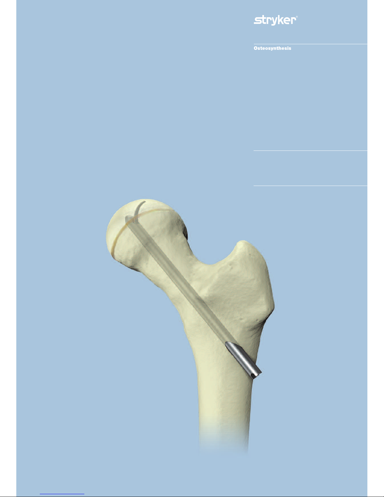
Introduction
The Hansson™ Pin system, designed
by Professor Lars Ingvar Hansson at
the University of Lund in Sweden,
w
as developed based on research
concerning the effects of implants on
the blood supply to the femoral head.
Specifically developed for the
treatment of slipped capital femoral
epiphysis, the Hansson Pin system has
been designed to minimise surgical
trauma to the patient and offer secure,
stable fixation with reduced risk of
healing complications for all grades
of fracture.
Twenty years of successful clinical
studies have been carried out to
enhance the Hansson™ Pin System
to its current form.
This work is summarized in 6 theses
and more than 70 published articles.
Rationale
The methodology involves a cylindrical
pin inserted in a drill hole which
attaches to the femoral head via a hook,
providing strong, stable fixation
through a simple and precise procedure.
The drill hole and pin run at right
angles to the growth zone and are,
depending on the degree of slipping,
r
e
lat
ively centrally located in the
femoral neck and head.
T
he pin is 10-20mm longer than the
dr
il
l hole t
o al
lo
w c
ontinued growth
in the length of the femoral neck.
S
lips of up to 60° can be stabilised
b
y ost
e
osynthesis.
Page 4
4
Relative Indications & Contraindications
Slipped Capital
Femoral Epiphysis
Adult Femoral Neck Fractures
The physician’s education, training and
professional judgement must be relied
upon to choose the most appropriate
d
e
v
ice and treatment.
Conditions presenting an increased
r
isk of implant failure include:
• Any active or suspected latent
infection or marked local
inflammation in or about the
aff
ected area.
•
C
ompromised vascularity that would
inhibit adequate blood supply to the
fracture or the operative site.
• Bone stock compromised by disease,
inf
e
c
tion or prior implantation that
can not p
r
o
v
ide a
dequate support
and/or fixation of the devices.
•
Material sensitivity, documented
o
r s
usp
ected.
•
O
b
esit
y. An obese patient can
produce loads on the implant that
can lead to failure of the fixation of
the d
e
v
ic
e or to failure of the device
itself.
• Patients having inadequate tissue
coverage over the operative site.
• Implant utilization that would
interfere with anatomical structures
or physiological performance.
•
A
n
y me
ntal or neuromuscular
disorder which would create an
unacceptable risk of fixation failure or
c
o
mplicat
io
ns in postoperative care.
•
O
the
r me
dical o
r surgical conditions
which would preclude the potential
benefit of surgery.
Detailed information is included in the
instructions for use being provided
with each implant.
See package insert for a complete list
o
f
potential adverse effects and
contraindications. The surgeon must
discuss all relevant risks, including the
se
r
vice life of the device and the need
for postoperative protection of the
implant with the child’s parents,
w
hen necessary.
Relative Contraindications
Contraindications
Indications
Due to a lack of any supportive
clinical experience, the Hansson Pin
is not recommended for use with
paediatric hip fractures.
Page 5
5
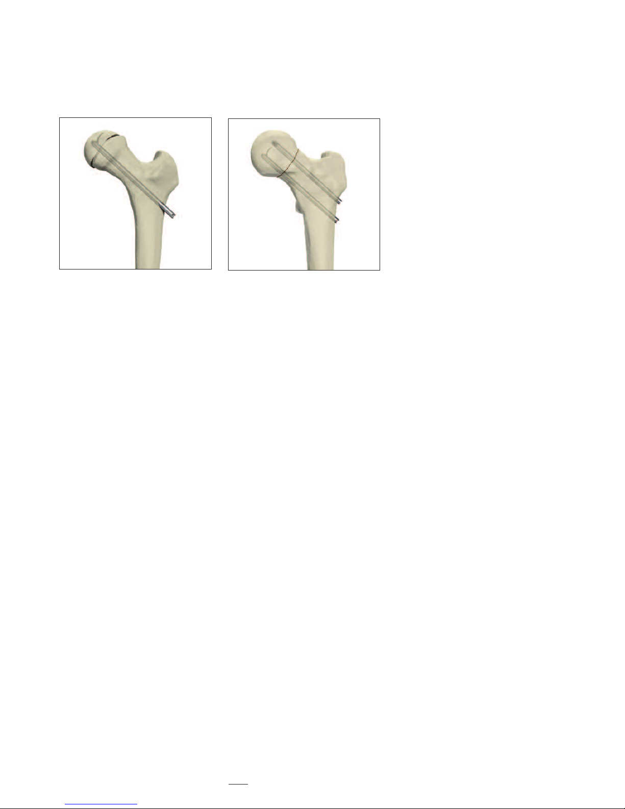
Features & Benefits
Preventing diastasis and further
displacement of the epiphysis
The risk of further intraoperative
d
isplacement of the femoral head is
reduced by drilling a channel for the
H
ansson Pin with the femoral head
fixed with kirschner wires. The smooth
outer pin allows the surgeon to gently
push the implant through the channel,
reducing the risk of diastasis between
the femoral neck and the head.
1
Lasting stable fixation
The hook resists loosening of the
fixation to the femoral head as the
longitudinal growth of the femoral
neck retracts the pin in the channel
thereby stabilizing the femoral head.
Loosening of the implant is potentially
reduced because of resorption and
growth of the femoral neck under
normal conditions.
1
Reducing the risk of unequal
bone length
The continued growth of the femoral
n
eck in cases with Slipped Capital
Femoral Epiphysis is an indication
o
f undisturbed intra- and postoperative
vascularization, as the nutrition for the
proliferating cells of the growth plate
is provided by the epiphysial vessels.
By preserving the blood supply,
the Hansson Pin System reduces
the risk of unequal bone length.
1
Easy extraction
The risk of the pin being trapped in
the bone is reduced as the pin surface
is smooth. The hook is easily
withdrawn back into the body of the
pin, which can then be removed.
1
Frontal view
Lateral view
Slipped Capital
Femoral Epiphysis
Page 6
6
Operative Technique
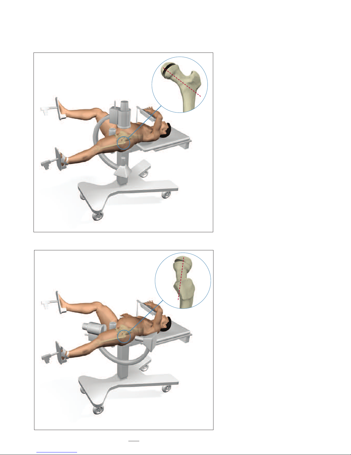
Step 1 - Patient Positioning
Correct positioning of the patient
on the fracture table is essential for
avoiding problems and complications
d
uring surgery (Fig. 1).
Place the patient in supine position
on the fracture table.
Healthy side: Position the leg on the
healthy side with the hip in flexion
and slight abduction so that the C-arm
can be adjusted intra-operatively for
both the anterior/posterior and the
lateral/medial views. This is necessary to
obtain a true lateral view of the femoral
neck and head (Fig. 2). The purpose of
this view is to avoid the penetration of
the end of the pin through the surface
of the femoral head.
Furthermore, again for avoiding pin
penetration, the surface of the femoral
head must be seen continuously when
moving the C–arm from the horizontal
position to the vertical position.
Slipped side: Position the hip in full
extension with neutral position
between abduction and adduction.
Fig. 1 – Position Patient; C-Arm in A/P View
Fig
.
2 – Position Patient; C-Arm in L/M View
Page 7

7
Operative Technique
Step 2 - Reduction
Apply the surgical boot to the foot.
Mild traction is applied for the sole
purpose of maintaining the leg in the
horizontal plane. Additional support
under the thigh may be necessary.
Rotate the foot internally by 30- 60°
and fix in position. This is so that the
femoral neck is parallel to the radiation
beam in the lateral view (Fig. 3).
Stable (Chronic) Slips
Eighty to ninety percent of slips are
stable (or chronic).
Stable slips are always pinned in situ.
Any attempt to perform a closed
reduction on a chronic slip may lead
to avascular necrosis.
Gradual bone remodelling has taken
place as a response to the insidious
slipping of the femur away from
the femoral head. (Fig. 4) This is
the body's natural attempt to adapt
the geometry of the proximal femur
in order to maintain a functional hip
joint. The remodelling is therefore
ossified and reduction is not possible.
The stable slip is pinned with the
intention of preventing further
slippage, as well as preventing the
possibility of acute-on-chronic
traumatic changes, which could be
devastating for the vascularization
of the femoral head.
The surgical treatment of a stable slip
can the
r
e
fore be planned in advance
but must be considered urgent.
Fig. 3 – Internal Rotation of the Hip
Fig. 4 – Bone Remodelling
30- 60°
Unstable (Acute) Slips
Unstable slips (where the event is
recent, the child cannot weight-bear
and the threat of avascular necrosis
of the femoral head is an immediate
danger) must be pinned without delay
from the moment of the patient's
arrival in the clinic.
This is an emergency situation.
Some chronic remodelling may be
noted on X-ray and again, this ossified
modification of the hip joint cannot be
reduced in surgery.
The acute or unstable portion of the
slip is treated with closed reduction
by internal rotation and then pinned.
The chronic portion is left as it is.
Page 8

8
Step 3 – Stabilization Guide
Wire Insertion
When treating unstable (acute)
s
lips
a Guide Wire may be used.
Using biplanar floroscopy, it is inserted
percutaneously in the trochanteric
region into the femoral neck and
h
ead for intraoperative stabilization.
(Fig. 5).
Fig
.
5
Operative Technique
Page 9

9
Step 4 – Determining the Incision
P
oint and Implant Position
S
lipping of the femoral head occurs
in a true posterior direction.
The Hansson Pin must be positioned
in the central part of the femoral head.
To achieve this, the pin must be
inserted anterior-laterally in the
greater trochanter and then directed
posteriorly (Fig. 6).
A prerequisite for being able to
correctly position the Hansson Pin
is to insert a Ø2.4mm Guide Wire
prior to drilling.
Guide Wire Insertion Point –
Anterior/ Posterior View:
Position a Guide Wire on the skin
of the anterior aspect of the thigh.
Verify by anterior/posterior
fluoroscopy that the Guide Wire
is in the correct position in the central
part of the femoral neck and head
(Fig. 7). Mark the position of the
Guide Wire on the anterior surface
of the thigh.
Lateral/ Medial View:
Now position the Guide Wire over the
skin on the lateral aspect of the thigh.
Verify by lateral/medial fluoroscopy that
the Guide Wire has been positioned to
e
nte
r p
ost
eriorly towards the central
part of the femoral head (Fig. 8)
M
ark the position of the Guide Wire
o
n the lat
e
r
al asp
ect of the thigh.
The intersection of these two lines at
the ant
e
r
io
r
-lat
e
ral aspect of the thigh
at the level of the lesser trochanter
r
e
p
resents the optimal point for
p
e
r
cu
tane
ous inse
r
tion of the Guide
Wire (Fig. 9).
Fig. 6 – Final Implant Position to Achieve
Fig. 8 – L/M X-Ray of Guide Wire over skin
Fig. 7 – A/P X-Ray of Guide Wire over skin
Fig. 9 – Incision and Guide Wire Insertion Point
Operative Technique
Page 10

10
Step 5 – Skin Incision and Guide
Wire Insertion
Make a 20mm incision at the site
where the two lines on the thigh
intersect. The insertion point on the
a
nterior-lateral face of the proximal
femur is identified at the level of the
l
esser trochanter (Fig. 10).
If harder cortical bone is anticipated
(such as with a child being treated
with chemotherapy), the surgeon may
prefer to pre-drill the cortex with the
optional drill.
I
nsert the Guide Wire over the Guide
Wire Bush and Drill Sleeve. Using a
p
ower drill, begin insertion from the
ant
erio-lateral cortex, crossing the
e
piphysis and targeting the center of
the femoral head. According to the
severity of the slip, the guide wire will
be in an oblique position in the
femoral neck.
Use frequent biplanar fluoroscopic
control to verify the alignment of
the Guide Wire in both the anterior/
posterior and lateral/medial plane.
This is to ensure that the centre of the
femoral head will be reached.
If the direction of the Guide Wire
appears to deviate from the centre
o
f
the femoral head, stop the
procedure, remove the Guide Wire,
and recommence until correct
positioning of the Guide Wire is
obtained (Fig. 11). Advance to within
5mm of the subchondral bone to
anticipate the necessary space for the
hook to be extruded.
R
emove the Guide Wire Bush.
Fig. 10 – Skin Incision
Operative Technique
Fig. 11 – Guide Wire Insertion
Final I
mplant P
osit
io
n t
o
A
chieve
Page 11

11
Step 6 – Drilling and
Measurement
Insert the Cannulated Drill over
the Drill Sleeve and the Guide Wire.
The Drill Sleeve is pressed against the
lateral cortex of the femur and the drill
i
s advanced towards the centre of the
femoral head (Fig. 12).
Use frequent fluoroscopy while
drilling to avoid medial migration
and penetration of the Guide Wire
through the joint surface of the
femoral head.
If medial migration is detected, remove
the Cannulated Drill and clean the
bone debris from the cannulation.
R
einsert the Cannulated Drill over
the G
uide Wire and Drill Sleeve and
advance to within 5mm of subchondral
bone.
Leave the Drill Sleeve in place.
Read the measurement shown on the
drill at the level of the lateral aspect of
the Drill Sleeve (See zoom of Fig. 12).
Choose a Hansson Pin which is about
15 to 20mm more than the
measurement shown. This is to allow
the femoral neck to continue its growth
along the pin and to ease pin removal
once the physis has closed and growth
has c
ompleted.
According to the amount of
subcutaneous tissue which covers
the G
r
eat
e
r Trochanter, a longer pin
protruding from the patient's lateral
cortex may not be tolerated.
Therefore the amount of pin which
may protrude is limited. In this case, a
smaller pin is used and a future
operation to replace the pin with a
longer one may be necessary.
Operative Technique
Fig. 12 – Drill and Measure
Direct reading of
the length
Page 12

12
Operative Technique
Step 7 – Instrument-to-Pin
Assembly
V
erify that the inner pin is completely
withdrawn in the window of the outer
b
ody and in correct position (Fig. 13).
Pass the Inner Introducer through the
Outer Introducer and screw it into
the Hansson Pin (Fig. 14). There are
unequal tabs on the Outer Introducer
which correspond with slots in the pin;
the tabs and slots should securely mate
when the Introducer Assembly is
screwed onto the Hansson Pin.
The handles of the Inner and Outer
Introducers need not be aligned.
F
ig.13
Fig. 14
Hansson Pin
Outer Introducer
Inner Introducer
Page 13

13
Step 8 – Insertion of the Hansson
Pin and Activation of the Hook
I
nsert the Hansson Pin with the
Introducer Assembly into the femoral
c
hannel which has been pre-drilled.
Ensure that the pin is fully inserted.
Use fluoroscopy to verify the position
of the Hansson Pin. (Fig 15).
There is an etched line on the handle
of the Outer Introducer which
indicates the Inner Pin’s point of exit.
Verify that this guide line is in alignment
with the femoral shaft. (Fig. 16).
Thus the hook will be extruded in
the superior direction as demonstrated
in figure 17.
Insert the tip of the Introducer Handle
through the hole in the Inner Introducer.
Maintain both the Outer and Inner
Introducers in position.
Turn the Introducer Handle clockwise
whilst gently pushing medially on the
introducer assembly. Continue turning
the Introducer Handle to completely
deploy the hook using biplanar
fluoroscopy. A mechanical stop is
provided by the Inner Introducer
(Fig. 17).
Operative Technique
F
ig. 15 – Insert Hansson Pin into channel
Fig. 16 – Verify hook position
Fig
.
17 – Activate hook
Page 14

14
Operative Technique
Step 9 – Instrument Removal
Maintain the Outer Introducer in
position. Unscrew and then remove
the Introducer Handle followed by
t
he Inner Introducer and the Outer
Introducer (Fig.18). Close the wound.
Fig.18
Page 15

15
Postoperative Regime
Stable Slip:
T
he patient is allowed to start walking
using crutches and partial weight
bearing on the operated side the first
day after surgery.
Usually the patient can be discharged
f
rom the ward one to two days after
surgery when he or she is capable of
walking with crutches.
Full weight bearing is possible after
one week.
Unstable Slip:
T
he patient is allowed to start walking
using crutches and partial weight
bearing on the operated side the first
day after surgery.
Full weight bearing on the operated leg
i
s not allowed until after six weeks.
Postoperative Activities Stable and Unstable:
Surgeons should instruct parents
regarding appropriate and restricted
activities during the treatment in order
to prevent placing excessive stress
on the implants which may lead
to fixation or implant failure and
accompanying clinical problems.
Surgeons should also instruct parents
to report any unusual changes of the
operative site to his/her physician.
The physician should closely monitor
the patient if a change at the site has
b
een detected.
Bilateral Slips:
Periodic X-Ray images should be taken
o
f both hips to facilitate early detection
of contralateral slips.
Follow Up Examination –
Stable and Unstable:
A six-week post-op follow up medical
and radiological examination is
recommended.
When assessing the follow-up X-ray,
the surgeon must look for:
• Reliable anchorage of the hook in the
femoral head.
• Protrusion of the end of the pin
through the lateral cortex of the
thigh.
The most accurate angle to view the
protrusion of the pin is the lateral
position, due to the insertion angle.
If the X-rays are satisfactory, then
walking is permitted.
R
e
p
eat X-r
a
ys are necessary every 6
months until the physes have closed.
Page 16

16
Operative Technique
Pin Removal
S
tep 1
The arrowed end of the Inner Extractor
is engaged with the inner pin’s thread
and rotated clockwise until it stops
(Fig. 18).
Step 2
The Outer Extractor is slid over the
Inner Extractor until it is in contact
with the outer pin (Fig. 19).
Note: If the Outer Extractor is not in
contact with the outer body of
the H
ansson Pin, rotate the
Outer Extractor
only until it
engages the flat sides of the
Inner Extractor and push
the handle gently until it touches
the tip of the outer body.
It is important not to exert any
rotation on the Outer Extractor
when the instrument is keyed
by the flat sides of the Inner
Extractor.
Step 3
Maintain the Outer Extractor in place.
I
nse
r
t the thr
eaded tip of the Extractor
Handle into the Outer Extractor and
turn it clockwise to engage the
thread
e
d part of the Inner Extractor
Do not rotate the Outer Extractor.
See step (1) in figure 20.
Continue to turn the Extractor Handle
until a mechanical stop is felt.
This completely withdraws the hook
into the outer pin.
Check under image intensification
that the hook is fully retracted prior
to pulling back the implant.
Once the hook is fully retracted,
remove the implant along with the
e
xtraction instruments.
See step (2) in figure 20.
I
n case the hook is removed on its
own, leaving behind the outer pin, the
outer pin is removed by assembling the
Inner and Outer Introducers and
removing the outer pin from the bone.
F
ig. 18 – Engage Inner Extractor with Inner Pin
Fig. 19 – Key Outer Extractor over Inner Extractor
Fig. 20 – Insert and turn Extractor Handle
(1)
(2)
Page 17

17
Ordering Information — Implants
Stainless Steel Pin Titanium
REF Length REF
mm
394070S 70mm 694070S
394075S 75mm 694075S
394080S 80mm 694080S
394085S 85mm 694085S
394090S 90mm 694090S
394095S 95mm 694095S
394100S 100mm 694100S
394105S 105mm 694105S
394110S 110mm 694110S
394115S 115mm 694115S
394120S 120mm 694120S
394125S 125mm 694125S
394130S 130mm 694130S
394135 * 135mm 694135*
394140 * 140mm 694140*
HANSSON PINS
Sp
ecial Order
N
ot
e:
St
e
r
ile Onl
y /
* Sp
e
cial Or
d
e
r N
o
n-St
erile
Page 18

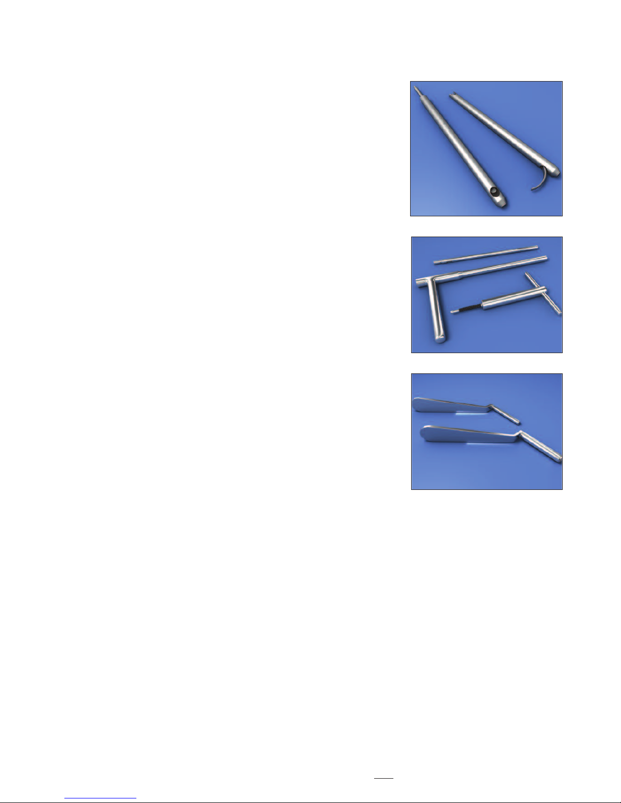
18
Ordering Information — Instruments
REF Description
704501 Short Cannulated Drill Ø 6.7mm x 246mm with Jacobs fitting
704510 Protective Measuring Sleeve
704511 Guide-wire Bush
704515 Outer Introducer
704516 Inner Introducer
704517 Introducer Handle
704527 Extractor Handle
704528 Outer Extractor
704529 Inner Extractor
704505S Threaded Guide-wire Ø 2.4mm x 300mm (Single Use - Sterile Packed)
901704
St
erilisation Tray for Instruments (Lid and Insert)
O
p
t
io
nal Instrument
702448 Drill Bit Ø 1.4mm x 150mm (single use).
Page 19

19
References
References:
1. Hansson L.I. (1982): Osteosynthesis
w
ith the Hook-Pin in Slipped Capital
Femoral Epiphysis. Acta Orthop. Scand.
53: 87-96
2. Slipped Capital Femoral Epiphysis
Journal of Pediatric Orthopaedics.
26(3):286-290, May/June 2006.
Lehmann, Charles L. BS *; Arons,
Raymond R. PhD +; Loder, Randall T.
MD ++; Vitale, Michael G. MD, MPH +[S]
3. Bone Growth After Fixing Slipped
Femoral Epiphysis: Brief Report
J Bone Joint Surg (Br) 1988 ;70-B : 846-6.
Hägglund, Gunnar ; Bylander, Birger ;
Hansson, Lars Ingvar ; Selvik, Göran.
4. Radiographic Assessment of
Coxarthrosis Following Slipped Capital
F
emoral Epipysis, A 32-year follow-up
study of 51 hips.
Acta Radiologica 34 (1993) Fasc. 2
Hansson, G.; Jerre, R.; Sanders, S.M.;
Wallin, J.
5. The Contralateral Hip in Patients
Primarily Treated for Unilateral Slipped
Upper Femoral Epiphysis, a long-term
follow-up of 61 hips
J Bone Joint Surgery (Br) 1994; 76B:563-7.
Jerre, Ragnar; Billing, Lars; Hansson,
Göran; Wallin, Jan
6. L
o
ng-term Results After Nailing in situ
of Slipped Upper Femoral Epiphysis
A 30-year follow-up of 59 hips.
T
he J
our
nal of Bone and Joint Surgery
(Br) 1998;80-B:70-7
Hansson, G; Billing, B.; Högstedt, B.;
J
e
r
re, R.; Wallin, J.
7. Prophylactic Pinning of the
C
ontralateral Hip in Slipped Capital
Femoral Epiphysis
Evaluation of Long-Term Outcome
for the Contralateral Hip with Use
of Decision Analysis
J
ournal of Bone and Joint Surgery, Inc.
2002
W. Randall Schultz, MD, MS, James N.
Weinstein, DO, MS, Stuart L. Weinstein,
MD and Brian G. Smith, MD
8. The Epidemiology of Slipped Capital
Femoral Epiphysis: An Update
Paper No: 050 Presented at the American
Academy of Orthopaedic Surgeons
2005 Annual Meeting, Washington, DC –
February 23, 2005
Michael G Vitale, MD; Charles Lehmann
BS; Randall T Loder, MD
9. Osteosynthesis with the Hook-Pin in
Slipped Capital Femoral Epiphysis,
Hansson, L.I. (1982):
Acta Orthop. Scand. 53: 87-96
10. Vitality of the Slipped Capital
Femoral Epiphysis. Preoperative
evaluation by tetracycline labeling.
Hagglund, G., Hansson, L.I. and
Ordeberg G. (1985).
T
hesis:
1. Physiolysis of the Hip. Epidemiology,
n
atural history and long time results
after closed treatment.
Gunnar Ordeberg, 1986.
2. Physiolysis of the Hip. Epidemiology,
etiology and therapy.
Gunnar Hägglund, 1986.
Page 20

Stryker Trauma AG
Bohnackerweg 1
CH-2545 S
e
lza
c
h
Switzerland
www
.osteosynthesis.stryker.com
T
he inf
ormation presented in this brochure is intended to demonstrate a Stryker product. Always refer to the package
inse
r
t,
p
roduct label and/or user instructions before using any Stryker product. Surgeons must always rely on their own
clinical judgment when deciding which products and techniques to use with their patients. Products may not be available
in all markets. Product availability is subject to the regulatory or medical practices that govern individual markets. Please
contact your Stryker representative if you have questions about the availability of Stryker products in your area.
Stryker Corporation or its subsidiary owns the registered trademark: Stryker.
S
wemac Orthopaedics AB owns the following trademark: Hansson Pin.
Literature Number:
982303
LOT A2806
US P
at
ents pending
Copyright © 2006 Stryker
Printed in Switzerland
 Loading...