

Page 1

STRYKER GLIDE™
Lateral Patient Transfer System
Model 3061
Operations/Maintenance Manual
For Parts or Technical Assistance:
USA: 1-800-327-0770 (option 2)
Canada: 1-888-233-6888
2008/05 3061-009-001 REV A www.stryker.com
Page 2

Page 3

Table of Contents
Introduction...............................................................................4
Intended Use ..........................................................................4
Product Description .....................................................................4
Product Illustration ......................................................................4
Specifications .........................................................................5
Warning / Caution / Note Definition ..........................................................6
Symbols .................................................................................7
Requirements By Symbol For Patient Transfer and Mattress Inflations .................................7
Summary of Safety Precautions................................................................8
Operation Guide ..........................................................................10
Selecting Appropriate Mattress Size ........................................................10
Positioning Mattress Underneath The Patient ................................................. 10
Connecting The Air Supply ...............................................................11
Transfer Of Patient From Stretcher To Bed ...................................................12
Preventative Maintenance ...................................................................13
Maintenance Checklist ..................................................................13
Cleaning................................................................................14
Routine Care: Mattress .................................................................14
Routine Care: Protective Sheet ...........................................................14
Routine Care: Blower Unit ...............................................................15
Disinfection ..........................................................................15
Blood Contamination ................................................................... 15
Troubleshooting Guide......................................................................16
Service Information ........................................................................ 17
Hose Replacement.....................................................................17
Power Cord Replacement ............................................................... 17
ON/OFF Switch Replacement ............................................................. 17
Upper Housing Replacement..............................................................18
Blower Assembly Replacement ............................................................18
Quick Reference Replacement Parts List . . . . . . . . . . . . . . . . . . . . . . . . . . . . . . . . . . . . . . . . . . . . . . . . . . . . . . . . 19
3060-000-028 Replacement Part List (Regular) ................................................19
3060-000-032 Replacement Part List (Large)..................................................19
3060-000-046 Replacement Part List (Bariatric)................................................19
Blower Unit Assembly, Standard - 3060-400-110 ...................................................20
Blower Base with Feet - 3060-001-125 ..........................................................22
Hose Assembly, Standard - 3060-001-127........................................................23
Hose Assembly, Optional 25’- 3060-045-002 .....................................................24
Mattress Assemblies .......................................................................25
Tote Assembly - 3060-001-041 ...............................................................26
Warranty................................................................................27
Limited Warranty ......................................................................27
To Obtain Parts and Service ..............................................................27
Return Authorization....................................................................27
Damaged Merchandise..................................................................27
EMC Information ..........................................................................28
www.stryker.com 3061-0 09 -001 RE V A 3
Page 4
Introduction
INTENDED USE
This manual is designed to assist you with the safe operation and maintenance of the GLIDE™. Carefully read this manual
thoroughly before using the equipment or beginning maintenance on it. To ensure safe operation of this equipment, it is
recommended that methods and procedures be established for educating and training staff on the safe operation of this
GLIDE™.
PRODUCT DESCRIPTION
The GLIDE™ includes one model for use in the United States and Canada. The GLIDE™ transfers a patient on a soft
nylon mattress designed with hundreds of tiny perforations on the underside. The air supply attaches to the mattress
and pumps air out through the tiny perforations on the underside of the mattress The continuous air flow helps to reduce
friction between the sleep surface and the GLIDE™ Matt allowing the operator to transfer the patient with ease.
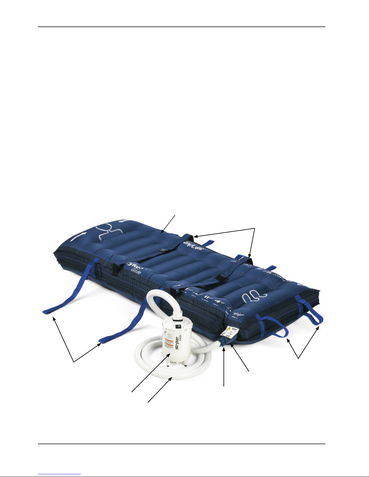
PRODUCT ILLUSTRATION
Extended Pull
Handles
Blower Assembly
Hose Assembly
Stryker GLIDE™ Matt
Patient Centering Straps
Extended Pull
Handles
Hose
Connection
Air Hose
Retention
Strap
Return To Table of Contents
4 3061- 00 9-0 01 REV A w ww.stryker.com
Page 5
Introduction
SPECIFICATIONS
Mattress
3061-110-028
Regular (width x length)• 28” x 78” 71,1 cm x 198,1 cm
Weight (including protective cover)• 3.5 lbs. 1.6 kg
Patient Capacity Limit•
Weight Limit• 500 lbs. 226.8 kg
Width Limit• 28” 71 cm
Nylon, Polyurethane under coated, water resistant, anti-static, non-latex•
3061-110-032
Large (width x length)• 32” x 78” 81,3 cm x 198,1 cm
Weight (including protective cover)• 5 lbs. 2.3 kg
Patient Capacity Limit•
Weight Limit• 700 lbs. 317.5 kg
Width Limit• 32” 81,3 cm
Nylon, Polyurethane under coated, water resistant, anti-static, non-latex•
3061-110-046
Bariatric (width x length)• 46” x 80” 116,8 cm x 198,1 cm
Weight (including protective cover)• 6.5 lbs. 2.9 kg
Patient Capacity Limit•
Weight Limit• 1000 lbs. 453.6 kg
Width Limit• 46” 116,8 cm
Nylon, Polyurethane under coated, water resistant, anti-static, non-latex•
Protective Sheet
3061-120-028 34” x 79” 86,4 cm x 200,1 cm
3061-120-032 36” x 79” 91,4 cm x 200,1 cm
3061-120-046 54” x 82” 137,2 cm x 208,3 cm
Air Supply / Power Requirements
Domestic
3060-001-210 (US / CAN)
Duty Cycle 30 seconds ON / 1 minute OFF for 5 cycles followed by a 30 minute rest period.
Product Compliance
Electrical
Weight 8.5 lbs. 3.9 kg
IEC/EN 60601-1
UL 60601-1
CAN/CSA-C22.2 No 601.1-M90
IEC/EN 60601-1-2:2001
120 VAC, 50/60 Hz, 12Amps
Power Cord - ST 2-16 Type w/NEMA 115P
Polarized Plug
Return To Table of Contents
www.stryker.com 3061-0 09 -001 RE V A 5
Page 6
Introduction
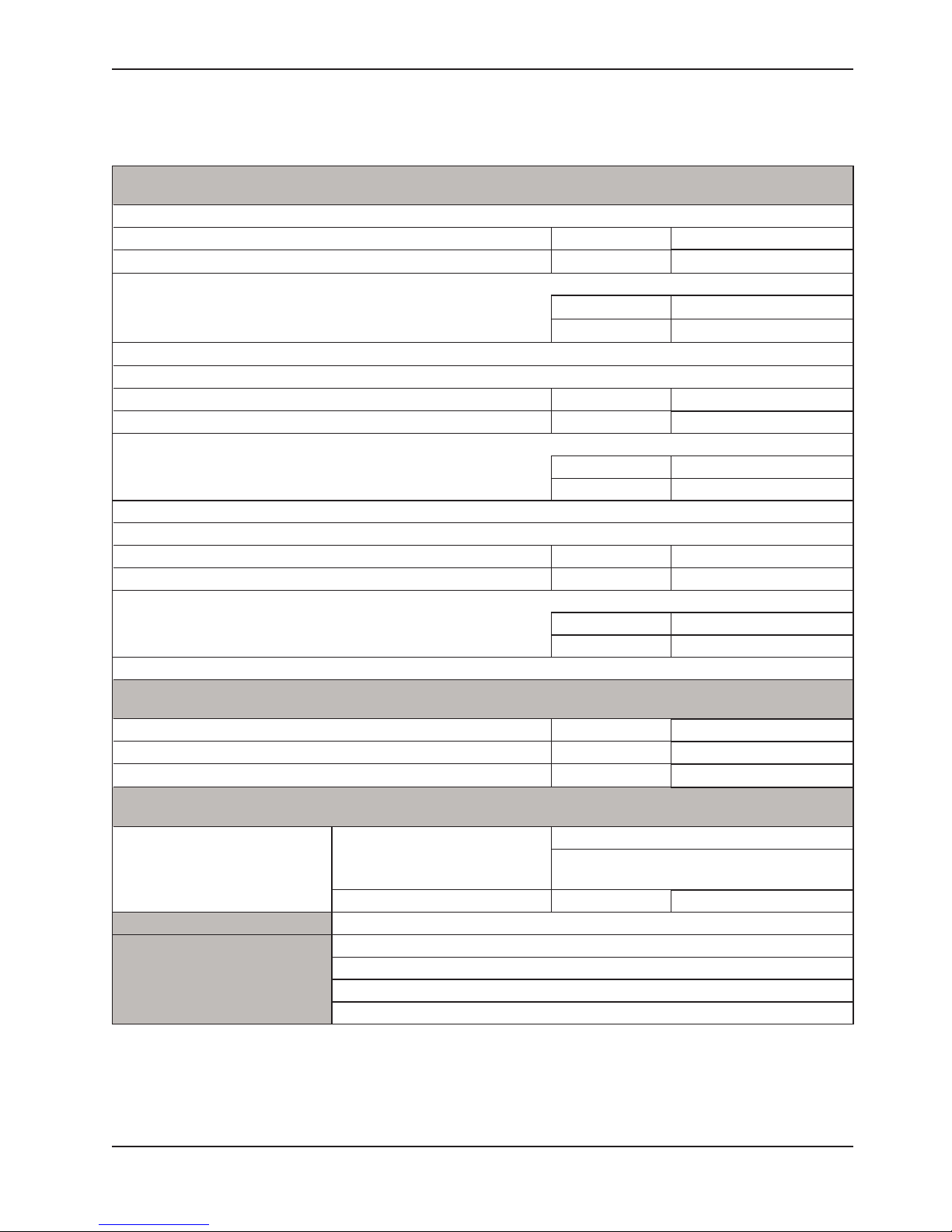
SPECIFICATIONS (CONTINUED)
Environmental Conditions Operation Storage and Transportation
30 0C
Ambient Temperature
Relative Humidity
(Non-Condensing)
Atmospheric Pressure
Stryker reserves the right to change specifications without notice.
Specifications listed are approximate and may vary slightly from unit to unit or by power supply fluctuations.
10 0C
(50 0F)
30%
700 hPa
(86 0F)
-25 0C
(-13 0F)
75%
10%
1060 hPa
500 hPa
60 0C
(140 0F)
95%
1060 hPa
WARNING / CAUTION / NOTE DEFINITION
The words WARNING, CAUTION, and NOTE carry special meanings and should be carefully reviewed.
WARNING
Alerts the reader about a situation, which if not avoided, could result in death or serious injury. It may also describe
potential serous adverse reactions and safety hazards.
CAUTION
Alerts the reader of a potentially hazardous situation, which if not avoided, may result in minor or moderate injury to the
user or patient or damage to the equipment or other property. This includes special care necessary for the safe and
effective use of the device and the care necessary to avoid damage to a device that may occur as a result of use or
misuse.
Note
This provides special information to make maintenance easier or important instructions clearer.
Return To Table of Contents
6 3061- 00 9-0 01 REV A w ww.stryker.com
Page 7
Symbols
~
Warning / Caution - Consult accompanying documentation
Maximum Safe Working Load
Maximum Patient Width
Alternating Current
Class II Equipment: Equipment in which protection against electric shock does not rely on basic insulation
only, but in which additional safety precautions such as double insulation or reinforced insulation are
provided, there being no provision for protective earthing or reliance upon installation conditions.
Type B Equipment: equipment providing a particular degree of protection against electric shock,
particularly regarding allowable leakage current and reliability of the protective earth connection.
O
I
IPX0
Indicates Power Off position on black power rocker switch
Indicates Power On position on black power rocker switch
No protection against harmful ingress of water.
Medical Equipment Classified by Underwriters Laboratories Inc. with respect to Electric Shock, Fire,
Mechanical and Other Specified Hazards Only in Accordance with UL 60601-1, First Edition (2003) and
CAN/CSA C22.2 No. 601.1-M90 with updates 1 and 2.
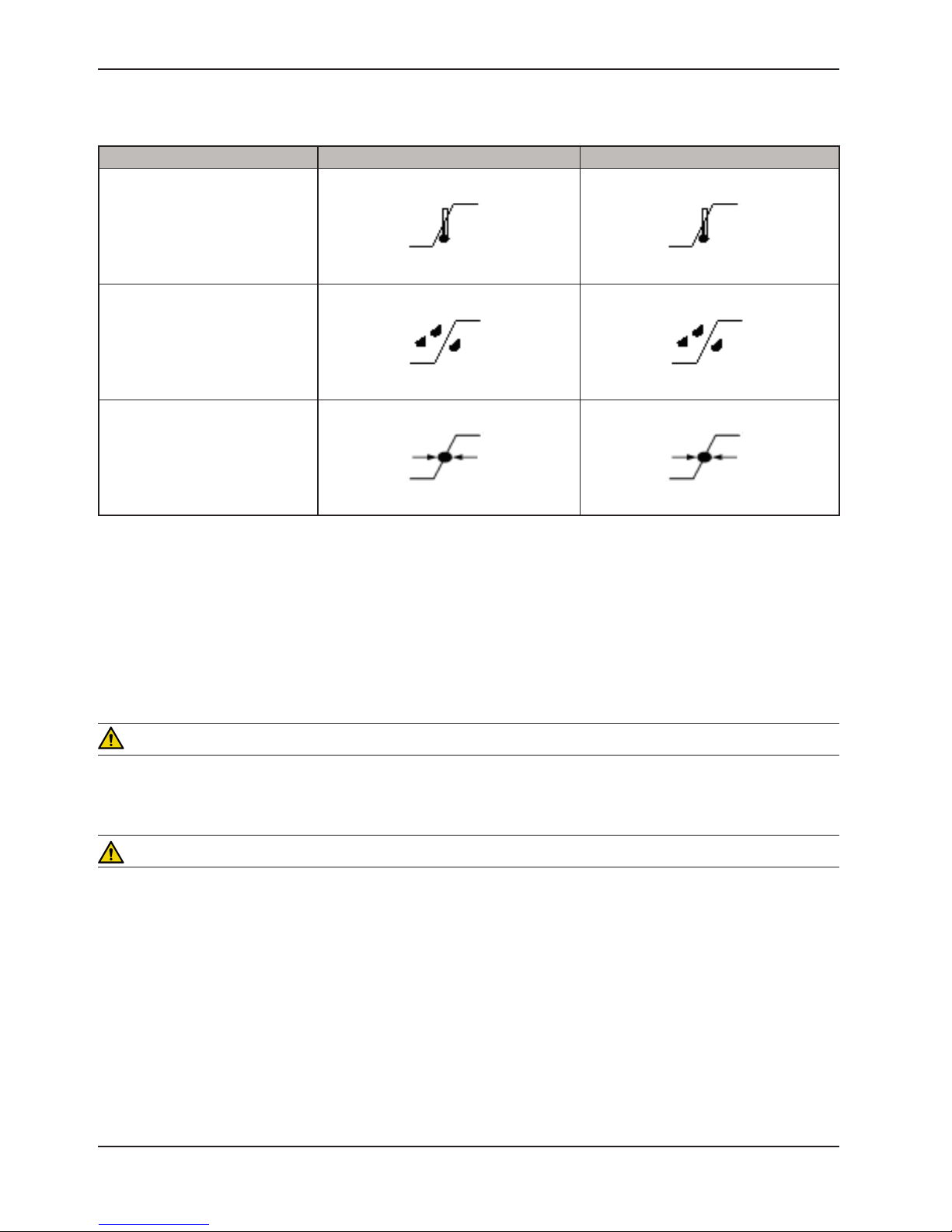
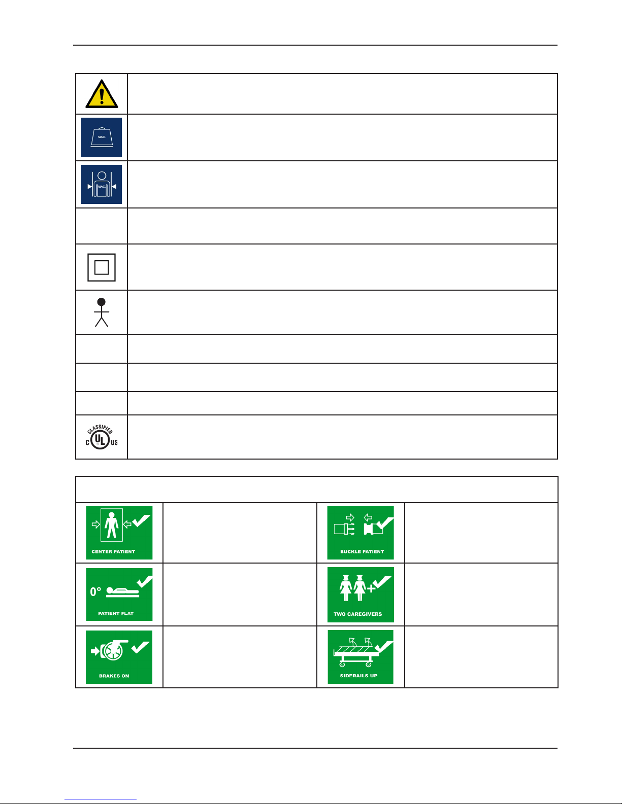
REQUIREMENTS BY SYMBOL FOR PATIENT TRANSFER AND MATTRESS INFLATIONS
Patient must be centered on mattress
prior to starting inflation process.
Patient Support Platform must be
at a position of zero Trendelenburg
prior to starting inflation process.
Patient Support Platform brakes
must be set to “ON” prior to starting
inflation process.
Patient must be secured on the
mattress prior to starting inflation
process.
A minimum of two caregivers
is required when transferring a
patient.
Patient Support Platform siderails
must be in the “UP” position prior
to starting inflation process or
transferring a patient.
www.stryker.com 3061-0 09 -001 RE V A 7
Return To Table of Contents
Page 8

Summary of Safety Precautions
WARNINGS
Never leave patient unattended while the GLIDE™ mattress is inflated and air supply is on.•
The GLIDE™ equipment is not suitable for use in the presence of a flammable anesthetic mixture with air, oxygen •
or nitrous oxide.
Mattress must be oriented so that white symbols are pointing upwards.•
The GLIDE™ is not to be used as an air mattress for patient stays with the blower on.•
Do not place and operate the GLIDE™ blower unit in close proximity to uncontainable fluids or biomass.•
Medical electrical equipment requires special precautions regarding EMC and needs to be installed and put into •
service according to the EMC information provided on page 28 to prevent equipment malfunction. Portable and
mobile RF communication equipment can affect Medical Electrical Equipment.
The GLIDE™ is not to be used in the presence of flammable anesthetics.•
The GLIDE™ is not to be used in oxygen rich environments or hyperbaric chambers•
The GLIDE™ is not to be used in the presence of open sources of ignition such as cigarettes, etc…•
Patient straps are used to center patient on the product during inflation and deflation. They are not intended to be •
safety restraint straps that keep the patient on the stretcher or bed.
The GLIDE™ blower and mattress are not to be used as a patient warmer.•
The GLIDE™ blower is not to be used with other manufacturers air transfer mattresses.•
The GLIDE™ air transfer mattress is not to be used with other manufacturing blowers. •
Patient is to be centered before and during inflation.•
Patient support surface (i.e. stretcher, bed, operating table, etc…) must be at 0˚ trendelenburg or level to prevent the •
patient moving under their own weight. The patient support surface should be level with one another.
When using the GLIDE™ side rails must be raised to act as guards to stop the patients movement during a •
transfer.
When using the GLIDE™ for transfers between products that have a transfer gap greater than three inches, the •
transfer bridge must be used. The transfer bridge is not meant to support a patient load. The transfer bridge is
meant to ease transfer of a patient from one patient support surface (i.e. stretcher, bed, etc.) to another. Always
insure that the patient support surfaces and their respective transfer gaps are adequate to support the patient.
The GLIDE™ is to be used with a minimum of two care givers. Care givers need to be positioned so that they can •
control positioning of patient.
The GLIDE™ must be centered under patient without any bunching present. Bunching will cause patient to be •
pushed / lifted off center.
The GLIDE™ can only be used on transfers between fixed patient support surfaces. Mobile surfaces need the •
brakes applied to make them a fixed surface.
Stow accessories such as the Stryker pop-up push handles before beginning a transfer using the GLIDE™.•
Return To Table of Contents
8 3061- 00 9-0 01 REV A w ww.stryker.com
Page 9

Summary of Safety Precautions
CAUTIONS
Do not operate air supply motor near equipment that is sensitive to electromagnetic interference.•
There is a weight limit on the mattress, the bed, gurney or other surface that the mattress is being used on. Adhere •
to all weight limits as stated in accompanying documentation.
Insert hose into matt and secure with Velcro strap.•
Inspect mattress for seam failures.•
Do not leave the GLIDE™ mattress under patients susceptible to decubitus ulcers.•
Do not leave patients laying on the buckles of the centering straps. •
To avoid malfunction, this product should not be used adjacent to or stacked with other equipment. If stacked use is •
necessary, this product should be observed to verify normal operation in the configuration in which it will be used.
The mattress size is specified in two ways; by the weight of the patient and by the physical size of the patient. •
Selection of an inappropriately sized matt may reduce the overall transfer performance of the Glide or may cause
harm to the patient or the caregiver.
Note
Maximum leakage current shall not exceed 100 micro amps on air supply enclosure and 100 micro amps on air •
mattress.
No automatic pressure relief exists on device. •
www.stryker.com 3061-0 09 -001 RE V A 9
Return To Table of Contents
Page 10

Operation Guide
Operating the GLIDE™ is a three step process; positioning the mattress under patient, connecting air supply, then
transferring patient from stretcher to bed. See detailed instructions below.
SELECTING APPROPRIATE MATTRESS SIZE
The mattress size is specified in two ways; by the weight of the patient and by the physical size of the patient. Selection
of an inappropriately sized mattress may reduce the overall transfer performance of the Glide or may cause harm to the
patient or the caregiver.
The selection of the appropriate size matt is characterized as follows:
28” mattress is appropriate for patients up to a weight of 500 lbs. and a maximum width of 28”.•
32” mattress is appropriate for patients up to a weight of 700 lbs. and a maximum width of 32”.•
46” • mattress is appropriate for patients up to a weight of 1000 lbs. and a maximum width of 46”.
Selection of the appropriate size mattress is determined by comparing the width of the patient to the width of the deflated
mattress. The width of the patient shall not exceed the width of the deflated mattress at any point along its length.
POSITIONING MATTRESS UNDERNEATH THE PATIENT
Note
The GLIDE™ is to be used with a minimum of two caregivers. Caregivers need to be positioned so that they •
can control positioning of the patient.
If soiling is possible, place protector sheet on top of mattress, dull side down, before it is positioned underneath •
the patient.
1. Roll the mattress lengthwise towards center from one side such that the side with the perforations will be against
the bed, not the patient.
2. Place the mattress under the patient using a “log-rolling” technique.
Note: Ensure the patient’s head is located at the same end as the “HEAD” label on the mattress topside.
a. Roll the patient onto their side toward the attendant, (the bed sheet can be used to help with the log roll).
b. Place the rolled edge of the mattress against the patient.
c. Roll the patient back towards the opposite side enough to unroll the mattress as you would when changing a
bed sheet.
d. Center the patient on the mattress.
3. Attach the two patient centering straps in gentle contact with the patient. Straps need not be tight.
Note: Do not pull on the patient centering straps to transfer the patient.
Return To Table of Contents
10 3061-0 09 -001 RE V A www.stryker.com
Page 11

Operation Guide
CONNECTING THE AIR SUPPLY
Ensure the ON/OFF (I / O) switch is positioned to “OFF” (O) as shown in 1.
Figure 1.1.
Note: Not confirming ON/OFF switch is positioned to “OFF” may result in
harm to the patient and/or operator of the device.
Plug the power cord of the air supply into the electrical outlet on 2.
the wall.
Attach one end of the flexible hose with the rubber grommet to 3.
the air supply as shown in Figure 1.2.
Insert the other end of the flexible hose into the mattress sleeve 4.
under the label flap as shown in Figure 1.2.
Note: Ensure that the hose cuff is fully inserted into the
mattress sleeve as shown in Figure 1.3.
OFF
Figure 1.1
Wrap the Velcro strap around the mattress sleeve as shown in 5.
Figure 1.4.
Note: The Velcro strap must be fastened around the flexible
hose, not the hose cuff.
Hose Cuff
Mattress Sleeve
Hose Cuff is
fully inserted.
Figure 1.3 Figure 1.4
Mattress
Sleeve
Figure 1.2
Velcro Strap
Using the air hose retention straps, secure the air hose to the mattress. 6.
Note: The air supply unit can remain in the roller bag if needed.
www.stryker.com 3061-0 09 -001 RE V A 11
Return To Table of Contents
Page 12

Operation Guide
TRANSFER OF PATIENT FROM STRETCHER TO BED
Position the stretcher alongside the patient’s bed as close as possible.1.
Securely engage the brakes on the Mobile Patient Support Platform.2.
Raise the stretcher siderail located opposite the patient transfer. 3.
Adju4. st the bed or stretcher height so that they are as close to the same level as possible.
Note: If the space between the patient’s bed and stretcher is greater than 3”, use the transfer bridge to fill
the gap.
Before turning air supply unit on, verify the following: 5.
a. Siderails, accessories or sharp object are not obstructing the path of the mattress.
b. The air hose should be free to travel with the mattress.
c. All patient support systems such as I.V. lines or oxygen hoses are free to travel with the patient.
d. An attendant is positioned in the direction of the patient transfer.
Turn “ON” the air supply by pressing the switch to the “I” position (Figure 2).6.
Wait approximately 10-15 seconds for the mattress to fully inflate.7.
Once mattress is fully inflated, grasp extended pull handles of mattress while 8.
keeping your back in the neutral ergonomic upright posture.
With one firm continuous pull, move the patient towards the attendant to the 9.
desired surface ending with the patient centered on the new surface.
Turn “OFF” air supply by pressing the switch to the “O” position (Figure 2).10.
Unplug power cord from wall and air supply.11.
Figure 2
ON
OFF
WARNING
Never leave patient unattended when mattress is inflated and air supply is on.
12 3061-009 - 001 R EV A www.stryker.com
Page 13

Preventative Maintenance
MAINTENANCE CHECKLIST
_____ All fasteners secure (reference all assembly drawings).
_____ Hose assembly is not damaged or leaking.
_____ Power switch is working properly.
_____ Power cord is not frayed and is attached to blower assembly.
_____ Plastic on the blower assembly is not damaged.
_____ Mattress holds air and all straps are intact.
_____ Current leakage not to exceed 100 micro amps.
Unit Serial Number:
Completed by: _______________________________________ Date: _________________
Return To Table of Contents
www.stryker.com 3061-0 09 -001 RE V A 13
Page 14

Cleaning
CAUTION
Do not use harsh cleaners or solvents on mattress fabric.•
Follow all manufacturer directions for dilution of concentrated cleaning agents.•
Machine laundering or drying of mattress fabric is not recommended.•
Do not wash the mattress fabric in hot water.•
Do not iron the mattress fabric. •
Do not use Iodophor type disinfectants on the mattress fabric.•
The materials used to manufacture the mattress fabric and the performance of the fabric may be adversely •
affected by permitting any cleaning agent to remain in contact with the fabric for a prolonged duration or a failure to
adequately rinse the agent from the fabric.
Do not immerse blower unit in any water or cleaning solutions. • Hand wash the blower unit exterior surface only.
Ensure water or cleaning solutions do not come in contact with any inner components of the blower unit. Dry
thoroughly before putting the blower unit back into service.
Do not PRESSURE WASH, HOSE OFF or ULTRASONICALLY CLEAN the Blower Unit.•
Failure to follow said CAUTIONS may result in damage to the mattress, protective sheet or blower unit. •
ROUTINE CARE: Mattress
Wipe fabric clean with lukewarm water and a mild cleaning agent. •
Suggested cleaning agent:
10% bleach and water or;•
Any properly diluted EPA approved phenolic or quaternary cleaning solution.•
The cleaning solution should be sprayed on or applied with paper towels or disposable cleaning cloths using hospital •
protocol for bed mattresses.
The mattress and sheet should be wiped down with the suggested cleaning agent in between patient use.•
Hard to Clean Areas: Soft sponge with liquid cleaner as specified on manufacturer’s product label. •
To control or prevent odors on long term incontinent applications, clean mattress daily. The use of a scented •
cleaner/disinfectant is recommended.
Rinse thoroughly and allow drying before returning to service.•
ROUTINE CARE: Protective Sheet
Wipe fabric clean with lukewarm water and a mild cleaning agent. •
Suggested cleaning agent:
10% bleach and water or;•
Any properly diluted EPA approved phenolic or quaternary cleaning solution.•
The cleaning solution should be sprayed on or applied with paper towels or disposable cleaning cloths using hospital •
protocol for bed mattresses.
The mattress and sheet should be wiped down with the suggested cleaning agent in between patient use.•
Hard to Clean Areas: Soft sponge with liquid cleaner as specified on manufacturer’s product label. •
To control or prevent odors on long term incontinent applications, clean mattress daily. The use of a scented •
cleaner/disinfectant is recommended.
Rinse thoroughly and allow drying before returning to service.•
For heavily soiled Protective Sheets, machine laundering can be performed. Recommended cleaners include neutral •
detergent or 10% bleach and water solution. Water temperature should not exceed 150 degrees Fahrenheit.
The Protective Sheet should be air dried if possible. Machine drying can be performed as long as the maximum air •
or drum temperature does not exceed 120 degrees Fahrenheit.
Return To Table of Contents
14 3061- 00 9-0 01 REV A w ww.stryker.com
Page 15

Cleaning
ROUTINE CARE: Blower Unit
CAUTION
Do not immerse blower unit in any water or cleaning solutions. Hand wash the blower unit exterior surface only. Ensure
water or cleaning solutions do not come in contact with any inner components of the blower unit. Dry thoroughly before
putting the blower unit back into service.
Hand wash all surfaces of the blower unit with lukewarm water and a mild cleaning agent. •
Suggested cleaning agent:
10% bleach and water or;•
Any properly diluted EPA approved phenolic or quaternary cleaning solution. •
When a mild cleaning agent is not adequate, follow the instructions provided by the cleaning product manufacturer •
for ammonia, bleach, isopropyl alcohol, and ammonium chloride based cleaning solutions. Dampen a soft cloth with
the diluted cleaner and wipe all surfaces of the blower unit.
Dry thoroughly by wiping all surfaces with a dry cloth to remove any moisture.•
DISINFECTION
Most phenolic or quaternary type disinfectants can be used on the mattress fabric. User must dilute disinfectants •
and germicides in accordance with manufacturer’s instructions.
Iodophor type disinfectants (Betadine, for example) will stain the mattress fabric.•
BLOOD CONTAMINATION
The mattress fabric can be disinfected with a 1:10 dilution of household bleach (5.25% sodium hypochlorite) as •
recommended by the CDC (US Department of Health and Human Services, February 1989). Weaker dilutions, e.g.
1:100 may be used but may not be in accordance with CDC recommendations.
Note: Always wash hands thoroughly after cleaning the mattress, protective sheet or blower unit.
Return To Table of Contents
www.stryker.com 3061-0 09 -001 RE V A 15
Page 16

Problem / Failure Recommended Action
No Power to the Blower. Verify the switch is in the ON (I) position.1.
Troubleshooting Guide
Check the power outlet by trying another outlet.2.
Check the power cord for 120VAC. 3.
NOTE: The power cord plugs into the OFF (0) side of the switch.
a. Access the power cord connections by referencing page 17, “Power Cord
Replacement”, using a voltmeter between the power cord wires there
should be 120VAC with the power cord plugged into the wall.
i. If you do not have 120VAC, replace the power cord assembly.
ii. If you do have 120VAC, go to step b.
b. Check for continuity between the outlet end of the power cord and the
switch end of the power cord for both wires.
i. If you do not have continuity on one of the wires, replace the power
cord assembly.
ii. If you do have continuity, go to step 4.
Check the power switch for continuity. 4.
NOTE: The blower plugs into the ON (I) side of the switch.
a. Unplug the blower unit from the switch, using a voltmeter on one side
of the switch going between the ON and the OFF check for continuity
by moving the switch from ON to OFF.
i. If this was done on both sides and one or both sides with no
continuity, replace the power switch.
ii. If you do have continuity, replace the blower assembly.
Mattress will not inflate properly. Check the air hose assembly and the mattress assembly 1.
for any visual or audio air leaks and repair.
Check for blockage in the air hose assembly and repair.2.
Check for a strong volume of air from the blower assembly. 3.
a. Turn the blower on with the air hose assembly removed.
i. If the air volume diminished, check the air inlet on the lower housing
for restrictions and repair.
ii. If the there was no restriction in the lower housing, replace the
blower assembly.
Return To Table of Contents
16 3061-0 09 - 001 REV A www.stryker.com
Page 17

Service Information
HOSE REPLACEMENT
No Tools Required
Procedure:
Grab base of hose and turn counter-clockwise then remove.1.
Take the new hose and properly key the base of the hose to the upper housing of blower unit assembly then turn 2.
clockwise.
POWER CORD REPLACEMENT
Tools Required:
T-20 Torx Driver•
Phillips Head Screwdriver•
Procedure: Note - Reference Blower Unit Assembly page 20 when performing these procedures.
Unplug unit from the wall if it is plugged in.1.
Remove Hose Assembly.2.
Using a T-20 Torx driver, remove the two T-20 Torx screws that fasten the strain relief retainer to the upper housing.3.
Using a Phillips head screwdriver, remove the six Phillips head screws that fasten the upper housing to the main 4.
housing then remove the upper housing.
Disconnect the black and white wire connectors from the switch assembly.5.
Remove the power cord by pulling the black and white wires back up through the upper housing.6.
Install the new power cord.7.
Repeat the above steps in reverse order to reassemble. 8.
Note: Power cord connections are on the OFF (O) side of the switch.
Note: Do not overtighten the screws.
ON/OFF SWITCH REPLACEMENT
Tools Required:
Phillips Head Screwdriver•
Procedure:
Unplug unit from the wall if it is plugged in.1.
Remove Hose Assembly.2.
Using a Phillips head screwdriver, remove the six Phillips head screws that fasten the upper housing to the main 3.
housing then remove the upper housing.
Disconnect the power cord and the blower assembly connections from the switch assembly.4.
Remove the switch by pressing from the bottom and pull through the top of the upper housing.5.
Install the new switch assembly.6.
Repeat the above steps in reverse order to reassemble. 7.
Note: Power cord connections are on the OFF (O) side of the switch. Blower assembly connections are on
the ON (1) side of the switch.
Note: Do not overtighten the screws.
Return To Table of Contents
www.stryker.com 3061-0 09 -001 RE V A 17
Page 18

Service Information
UPPER HOUSING REPLACEMENT
Tools Required:
T-20 Torx Driver•
Phillips Head Screwdriver•
Wire Cutters•
Procedure:
Unplug unit from the wall if it is plugged in.1.
Remove Hose Assembly.2.
Using a Phillips head screwdriver, remove the six Phillips head screws that fasten the upper housing to the main 3.
housing and separate.4.
Remove the power cord (reference the Power Cord Replacement procedures on 5. page 17).
Remove the ON/OFF switch (reference the ON/OFF Switch Replacement procedures on 6. page 17).
Using wire cutters, cut the plastic cable tie that connects the blower assembly wire harness to the upper housing.7.
Remove the old upper housing assembly and install the new upper housing assembly.8.
Repeat the above steps in reverse order to reassemble. 9.
NOTE: Do not overtighten the screws.
BLOWER ASSEMBLY REPLACEMENT
Tools Required:
Phillips Head Screwdriver•
Diagonal Pliers•
Procedure:
Unplug unit from the wall if it is plugged in.1.
Remove Hose Assembly.2.
Using a Phillips head screwdriver, remove the six Phillips head screws that fasten the upper housing to the main 3.
housing then remove the upper housing.
Using wire cutters, cut the plastic cable that connects the blower assembly wire harness to the upper housing.4.
Disconnect the two blower assembly connectors from the switch assembly.5.
Using a Phillips head screwdriver, remove the six Phillips head screws that fasten the blower assembly to the bottom 6.
of the main housing.
Remove the blower assembly by grasping the blower assembly wire harness and lifting straight up and out of the 7.
main housing assembly.
Install the new blower assembly.8.
Install new wire tie.9.
Repeat the above steps in reverse order to reassemble. 10.
NOTE: Do not overtighten the screws.
Return To Table of Contents
18 3061-0 09 - 001 REV A www.stryker.com
Page 19

Quick Reference Replacement Parts List
Note
The parts and accessories listed on this page are all currently available for purchase. Please call Stryker Customer
Service (800)-327-0770 (Option 2).
3060-000-028 REPLACEMENT PART LIST (REGULAR)
Part Name Part Number
Air Mattress Assembly (includes Protective Sheet) 3061-500-028
Protective Sheet 3061-120-028
Transfer Bridge 3060-001-146
Blower Unit 3060-400-110
Power Cord 3060-001-802
Air Hose - 8’ 3060-001-127
Tote Assembly for GLIDE™ 3060-001-041
Hook Assembly 3060-001-130
3060-000-032 REPLACEMENT PART LIST (LARGE)
Part Name Part Number
Air Mattress Assembly (includes Protective Sheet) 3061-500-032
Protective Sheet 3061-120-032
Transfer Bridge 3060-001-146
Blower Unit 3060-400-110
Power Cord 3060-001-802
Air Hose - 8’ 3060-001-127
Tote Assembly for GLIDE™ 3060-001-041
Hook Assembly 3060-001-130
3060-000-046 REPLACEMENT PART LIST (BARIATRIC)
Part Name Part Number
Air Mattress Assembly (includes Protective Sheet) 3061-500-046
Protective Sheet 3061-120-046
Transfer Bridge 3060-001-146
Blower Unit 3060-400-110
Power Cord 3060-001-802
Air Hose - 8’ 3060-001-127
Tote Assembly for GLIDE™ 3060-001-041
Hook Assembly 3060-001-130
www.stryker.com 3061-0 09 -001 RE V A 19
Return To Table of Contents
Page 20

Blower Unit Assembly, Standard - 3060-400-110
Assembly Part Number: 3060-001-210 (reference only)
Return To Table of Contents
20 3061-0 09 -001 RE V A www.stryker.com
Page 21

Blower Unit Assembly, Standard - 3060-400-110
Blower Unit Assembly Components - 3060-001-210 (reference only)
Item Part No. Part Name Qty.
A 0023-119-000 Screw 2
B 0023-120-000 Phillips Head Truss Screw 12
C 0023-121-000 Phillips Head Truss Screw 3
D 3060-001-112 Housing 1
E 3060-001-113 Housing, Upper 1
F 3060-001-116 Gasket, Blower Bottom 1
G 3060-001-118 Gasket, Blower Top 1
H 3060-001-119 Gasket Blower Housing 1
J 3060-001-123 Gasket, Top Cover 1
L 3060-001-144 Gasket 1
M 3060-001-161 Switch 1
P 3060-001-802 Power Cord Assembly 1
R 3060-001-804 Blower Assembly 1
S 3060-001-125 Blower Base with Feet 1
T 3060-009-139 Spec Label 1
U 3060-009-153 Caution Label 1
W 3060-009-158 Instruction Label 1
X 3060-009-159 Serial Number Label 2
Z 3060-009-161 Stryker Glide™ Blower Label 1
AB 3060-001-169 Strain Relief Retainer 1
Return To Table of Contents
www.stryker.com 3061-0 09 -001 RE V A 21
Page 22

Blower Base with Feet - 3060-001-125
Item Part No. Part Name Qty.
A 0023-190-000 Phillips Head Truss Screw 4
B 3060-001-124 Blower Base 1
C 3060-008-003 Blower Base Bumper 4
Return To Table of Contents
22 3061-0 09 -001 RE V A www.stryker.com
Page 23

Hose Assembly, Standard - 3060-001-127
Item Part No. Part Name Qty.
A 3060-001-128 Hose, Standard 1
B 3060-001-129 Hose End Assembly 1
C 3060-001-137 Hose/Mattress Coupling 1
G 3060-001-131 Hose Coupling, Matt 1
H 3060-001-132 Hose Retainer Bracket 1
J 3060-001-133 Hose Gasket 1
www.stryker.com 3061-0 09 -001 RE V A 23
NOTE: PARTS NOT SOLD SEPARATELY.
Return To Table of Contents
Page 24

Hose Assembly, Optional 25’- 3060-045-002
NOTE: PARTS NOT SOLD SEPARATELY.
Item Part No. Part Name Qty.
A 3060-045-003 Hose, 25’ 1
B 3060-001-129 Hose End Assembly 1
C 3060-001-137 Hose/Mattress Coupling 1
G 3060-001-131 Hose Coupling, Matt 1
H 3060-001-132 Hose Retainer Bracket 1
J 3060-001-133 Hose Gasket 1
Return To Table of Contents
24 3061- 009 -001 RE V A www.stryker.com
Page 25

Mattress Assemblies
28” Regular - 3061-110-028 (reference only) 32” Large - 3061-110-032 (reference only)
78.0”
78.0”
28”
46” Bariatric - 3061-110-046
(reference only)
32”
78.0”
Return To Table of Contents
www.stryker.com 3061-0 09 -001 RE V A 25
46”
Page 26

Tote Assembly - 3060-001-041
Return To Table of Contents
26 3061-0 09 - 001 REV A www.stryker.com
Page 27

Warranty
LIMITED WARRANTY
Stryker Medical Division, a division of Stryker Corporation, warrants to the original purchaser the GLIDE™ to be free
from defects in material and workmanship for a period of one (1) year after date of delivery. Stryker’s obligation under
this warranty is expressly limited to supplying replacement parts and labor for, or replacing, at its option, any product
which is, in the sole discretion of Stryker, found to be defective. If requested by Stryker, products or parts for which a
warranty claim is made shall be returned prepaid to the factory. Any improper use or any alteration or repair by others
in such manner as in Stryker’s judgment affects the product materially and adversely shall void this warranty. Any
repair of Stryker products using parts not provided or authorized by Stryker shall void this warranty. No employee or
representative of Stryker is authorized to change this warranty in any way.
Stryker Medical’s GLIDE™ product is designed for an expected service life as listed below under normal use, conditions,
and with appropriate periodic maintenance as described in the maintenance manual for each device.
Blower Assembly: Five (5) years•
Matt Assembly: Two (2) years•
Tote Assembly: Five (5) years•
This statement constitutes Stryker’s entire warranty with respect to the aforesaid equipment. Stryker makes no
other warranty or representation, either expressed or implied, except as set forth herein. There is no warranty
of merchantability and there are no warranties of fitness for any particular purpose. In no event shall Stryker be
liable here under for incidental or consequential damages arising from or in any manner related to sales or use of
any such equipment.
TO OBTAIN PARTS AND SERVICE
Stryker products are supported by a nationwide network of dedicated Stryker Field Service Representatives. These
representatives are factory trained, available locally, and carry a substantial spare parts inventory to minimize repair
time. Simply call your local representative, or call Stryker Customer Service USA at 1-800-327−0770, Canada
1-888-233-6888.
RETURN AUTHORIZATION
Merchandise cannot be returned without approval from the Stryker Customer Service Department. An authorization
number will be provided which must be printed on the returned merchandise. Stryker reserves the right to charge
shipping and restocking fees on returned items. Special, modified, or discontinued items not subject to return.
DAMAGED MERCHANDISE
ICC Regulations require that claims for damaged merchandise must be made with the carrier within fifteen (15) days of
receipt of merchandise. Do not accept damaged shipments unless such damage is noted on the delivery receipt at
the time of receipt. Upon prompt notification, Stryker will file a freight claim with the appropriate carrier for damages
incurred. Claim will be limited in amount to the actual replacement cost. In the event that this information is not
received by Stryker within the fifteen (15) day period following the delivery of the merchandise, or the damage was not
noted on the delivery receipt at the time of receipt, the customer will be responsible for payment of the original invoice
in full. Claims for any short shipment must be made within thirty (30) days of invoice.
Return To Table of Contents
www.stryker.com 3061-0 09 -001 RE V A 27
Page 28

EMC Information
GLIDE™
Guidance and Manufacturer’s declaration - Electromagnetic Immunity
The GLIDE™ is suitable for use in the electromagnetic environment specified below. The customer or the
user of the GLIDE™ should assure that it is used in such an environment.
Immunity Test IEC 60601 Test Level Compliance Level
Electrostatic Discharge (ESD)
IEC 61000-4-2
Electrostatic fast
Transient/burst
IEC61000-4-4
Surge
IEC 61000-4-5
Voltage dips, voltage variations
and short interruptions on
power supply input lines
IEC 61000-4-11
Power frequency (50/60 Hz)
magnetic field
IEC 61000-4-8
Note: UT is the a.c. mains voltage prior to applications of the test level.
+6 kV contact
+8 kV air
+2 kV for power
supply lines
+1 kV for input/
output lines
+8 kV differential mode
+2 kV common mode
<5%Ut (95% dipUt) for 0,5
cycle
40%Ut (60% dop in Ut) for
5 cycles
70%Ut (30% dip in Ut) for
25 cycles.
<5% Ut (>95% dip in Ut)
for 5 sec.
3 A/m 3 A/m Power frequency magnetic
+6 kV contact
+8 kV air
+2 kV for power
supply lines
+1 kV for input/
output lines
+8 kV differential mode
+2 kV common mode
<5%Ut (95% dipUt) for
0,5 cycle
40%Ut (60% dop in Ut)
for 5 cycles
70%Ut (30% dip in Ut)
for 25 cycles.
<5% Ut (>95% dip in Ut)
for 5 sec.
Electromagnetic
Environment Guidance
Floors should be wood,
concrete, or ceramic tile. If
floors are covered with synthetic
material, the relative humidity
should be at least 30%.
Main power quality should be
that of a typical commercial or
hospital environment.
Main power quality is that of
a typical commercial and/or
hospital environment.
Main power quality should be
that of a typical commercial
and/or hospital environment.
If the user of the GLIDE™
requires continued operation
during power main interruptions,
it is recommended that the
device be powered from an
uninterrupted power supply or
a battery.
fields should be at levels
characteristic of a typical
location in a typical commercial
and/or hospital environment.
Return To Table of Contents
28 3061-0 09 - 001 REV A www.stryker.com
Page 29

EMC Information
GLIDE™ (CONTINUED)
Recommended separation distances between portable and mobile
RF communications equipment and the GLIDE™.
The GLIDE™ is intended for use in an electromagnetic environment in which radiated RF disturbances are
controlled. The customer or the user of the GLIDE™ can help prevent electromagnetic interferences by
maintaining a minimum distance between portable and mobile RF communications equipment (transmitters)
and the GLIDE™ as recommended below, according to the maximum output power of the communications
equipment.
Rated maximum output
power of transmitter
W
150 kHz to 80 MHz
0,01 1,12 0,12 0,23
0,1 0,38 0,38 0,73
1 1,2 1,2 2,3
Separation distance according to frequency of transmitter
m
d=1,2
80 MHz to 800 MHz
d=1,2
8000 MHz to 2,5 GHz
d=2,3
10 3,8 3,8 7,3
100 12 12 23
For transmitters rated at a maximum output power not listed above, the recommended separation distance d in meters
(m) can be estimated using the equation applicable to the frequency of the transmitter, where P is the maximum output
power rating of the transmitter in watts (W) according to the transmitter manufacturer.
NOTE 1
At 80 MHz and 800 MHz, the separation distance for the higher frequency range applies.
NOTE 2
These guidelines may not apply in all situations. Electromagnetic propagation is affected by absorption and reflection
from structures, objects and people.
Return To Table of Contents
www.stryker.com 3061-0 09 -001 RE V A 29
Page 30

EMC Information
GLIDE™ (CONTINUED)
The GLIDE™ is suited for use in the electromagnetic environment specified below. The customer or the
user of the GLIDE™ should assure that it is used in such an environment.
Immunity Test IEC 60601 Test Level Compliance Level Electromagnetic Environment - Guidance
Portable and mobile RF communications
equipment should be used no closer to any
part of the GLIDE™, including cables, than the
recommended separation distance calculated
from the equation appropriate for the frequency
of the transmitter.
Recommended Separation Distance
Conducted
RF
IEC 6100-4-6
Radiated RF
IEC 61000-4-3
3 Vrms
150 kHz to 80 MHz
3 V/m
80 MHz to 2,5 GHz
d=1,2
3 Vrms
3 V/m
d=1,2
80 MHz to 800 MHz
d=2,3
NOTE 1
At 80 MHz and 800 MHz, the higher frequency range applies.
NOTE 2
These guidelines may not apply in all situations. Electromagnetic propagation is affected by absorption and reflection
from structures, objects and people.
a
Field strengths from fixed transmitters, such as base stations for radio (cellular/cordless) telephones and land mobile
radios, amateur radio, AM and FM radio broadcast, and TV broadcast cannot be predicted theoretically with accuracy.
To assess the electromagnetic environment due to fixed RF transmitters, an electromagnetic site survey should be
considered. If the measured field strength in the location in which the GLIDE™ is used exceeds the applicable RF
compliance level above, the GLIDE™ should be observed to verify normal operation. If abnormal performance is
observed, additional measures may be necessary, such as reorienting or relocating the GLIDE™.
b
Over the frequency range 150 kHz to 80 MHz, field strengths are less than 3 V/m.
Return To Table of Contents
30 3061- 009-0 01 REV A www.stryker.com
Page 31

EMC Information
GLIDE™ (CONTINUED)
Guidance and Manufacturer’s declaration - Electromagnetic Emissions
The GLIDE™ is intended for use in an electromagnetic environment specified below. The customer or the
user of the GLIDE™ should assure that it is used in such an environment.
Emissions Test Compliance Electromagnetic Environment
The GLIDE™ uses RF energy only for its internal function.
RF Emissions
CISPR 11
RF Emissions
CISPR 11
Group 1
Class A
Therefore, its RF emissions are very low and are not
likely to cause any interference in nearby electronic
equipment.
The GLIDE™ is suitable for use in all establishments other
than domestic and those directly connected to the public
low voltage power supply network that supplies buildings
used for domestic purposes.
Harmonic Emissions
IEC 61000-3-2
Voltage Fluctuations
Flicker Emissions
IEC 6100-3-3
Class A
Complies
Return To Table of Contents
www.stryker.com 3061-0 09 -001 RE V A 31
Page 32

Page 33

UNITED STATES
UNITED STATES
Stryker Medical
Stryker Medical
3800 E. Centre Ave.,
3800 E. Centre Ave.,
Portage, Michigan USA
Portage, Michigan USA
49002
49002
CANADA
CANADA
Stryker Canada
Stryker Canada
45 Innovation Drive
45 Innovation Drive
Hamilton, Ontario Canada
Hamilton, Ontario Canada
L9H 7L8
L9H 7L8
EC REP
EC REP
European Representative
European Representative
Stryker France
Stryker France
ZAC Satolas Green Pusignan
ZAC Satolas Green Pusignan
Av. De Satolas Green
Av. De Satolas Green
69881 MEYZIEU Cedex
69881 MEYZIEU Cedex
France
France
2006/XX XXXX-XXX-XXX REV X www.stryker.com
2008/05 3061-009-001 REV A www.stryker.com
 Loading...