

Page 1

MAINTENANCE MANUAL
ELECTRIC MED/SURG BED
Model FL28C
TECHNICAL ASSISTANCE AND PARTS
Canada: 1 888 233-6888
United States: 1 800 327 0770
Outside Canada and the United States: Contact your local representative
Manufactured by Stryker
72-1079E MM FL28C REV A February 2009
F15-44-B Printed in Canada
Page 2

Page 3

TABLE OF CONTENTS
1. INTRODUCTION................................................................................................................... 5
1.1 Specifications ................................................................................................................. 5
1.2 Technical Support........................................................................................................... 6
1.3 Warning, Caution, Note Definition................................................................................... 6
1.4 Static Discharge Precautions.......................................................................................... 6
1.5 Warranty......................................................................................................................... 7
Limited Warranty .......................................................................................................... 7
To Obtain Service and/or Parts .................................................................................... 7
Return Authorization..................................................................................................... 8
Damaged Merchandise ................................................................................................ 8
1.6 Symbols.......................................................................................................................... 8
2. PREVENTATIVE MAINTENANCE ........................................................................................ 9
2.1 Bed Cleaning and Mattress Care.................................................................................... 9
2.2 Lubrication Requirements............................................................................................. 10
Actuator Screw Lubrication......................................................................................... 10
2.3 Preventative Maintenance Program.............................................................................. 12
Annual Checklist......................................................................................................... 12
Recommended Spare Parts ....................................................................................... 13
3. TROUBLESHOOTING ........................................................................................................ 15
3.1 Troubleshooting Guide.................................................................................................. 15
4. MAINTENANCE PROCEDURES ........................................................................................ 18
4.1 Siderail Maintenance Procedures ................................................................................. 18
Head Siderail Assembly Replacement........................................................................ 18
Head Rail Replacement.............................................................................................. 19
Head Siderail Mechanism Replacement..................................................................... 19
Foot Siderail Assembly Replacement......................................................................... 19
Foot Rail Replacement............................................................................................... 20
Foot Siderail Mechanism Replacement ...................................................................... 20
Siderail Outer Panel Membrane Replacement............................................................ 21
Speakerphone/Siderail Inner Panel Membrane Replacement..................................... 22
4.2 Foot Board Maintenance Procedures............................................................................ 24
Foot End Control Membrane Replacement................................................................. 24
Scale System LCD Display Replacement (Optional) .................................................. 25
4.3 Mattress Support Maintenance Procedures .................................................................. 26
Foot Section Replacement ......................................................................................... 26
Thigh Section Replacement........................................................................................ 27
Seat Section Replacement......................................................................................... 27
Head Section Replacement........................................................................................ 28
Fowler Actuator Replacement .................................................................................... 30
Knee Gatch Actuator Replacement ............................................................................ 32
Hi-Lo Actuator Replacement....................................................................................... 33
Motor Control Board Replacement ............................................................................. 35
Nurse Call (Optional) and GEN lll (optional) Control Board Replacement................... 36
Page 4

Nurse Call (Optional) Control Board Replacement......................................................36
Power Connector Replacement ..................................................................................37
Power Connector Fuse Replacement..........................................................................37
Scale Control Board/Bed Exit Buzzer (Optional) Replacement....................................38
Toroidal Transformer Replacement (100/200/220/240V International Series Beds -) ..39
Load Cell Replacement (Optional) ..............................................................................40
Scale Calibration (Optional) ........................................................................................41
Verifying the Scale Accuracy ....................................................................................41
Scale Calibration ......................................................................................................42
Auto Contour Micro Switch Replacement (Optional) ...................................................44
CPR Micro Switch Replacement (Optional).................................................................46
Micro Switch Attached to the Head Section Lever ....................................................46
Micro Switch Attached to the Frame.........................................................................47
CPR Activation Cable Replacement (Optional) ...........................................................47
CPR Pneumatic Cylinder (Optional)............................................................................47
4.4 Base Maintenance Procedures......................................................................................49
Brake/Steer Pedal Replacement.................................................................................49
Steer Wheel Caster Replacement...............................................................................50
Steer Wheel Assembly Replacement..........................................................................50
Steer Wheel Swing Arm Assembly Replacement........................................................51
Bed Caster Replacement............................................................................................52
Brake Rod Replacement.............................................................................................53
Appendix A: Circuit Diagrams...................................................................................................54
Appendix B: Maintenance Menu: Signification of Error Codes ..................................................58
Page 5

Introduction Chapter 1
1. INTRODUCTION
This manual is designed to assist in the servicing of the Stryker's FL28C Med/Surg Beds. Read
it thoroughly before beginning any service on the bed. Qualified maintenance personnel should
be able to refer to this manual at all time when servicing the bed.
This Maintenance Manual is an integral part of the bed and should be included if the bed is sold
or transferred.
1.1 SPECIFICATIONS *
Safe Working Load** 500 lb (227 kg)
Scale System (Optional)
- Capacity
- Accuracy
- Operating Angular Range
Overall Length/Width
- Siderails Up
- Siderails Down
Weight w/Boards 472 lb (214.1 kg)
Patient Sleep Surface 35 x 80" (89 x 203 cm) adjustable to 82" (208 cm) and
Recommended Mattress Size
Mattress Maximum Thickness
Min/Max Bed Height 14 1/2 to 29" (36.8 to 73.7 cm)
Fowler Angle 0 to 61°
Knee Gatch Angle
- with Auto Contour (optional)
- without Auto Contour
Trendelenburg/Reverse Trendelenburg +14 to -14°
Environmental Conditions
- Transport and Storage
- Ambient Temperature
- Relative Humidity
- Atmospheric Pressure
- Operating ***
- Ambient Temperature
- Relative Humidity
- Atmospheric Pressure
Electrical Requirements**** - all electrical
requirements meet CSA C22.2 No. 601.1,
UL 60601-1 and IEC 60601-1, 60601-2-38
specifications.
* Stryker pays special attention to product improvement and reserves the right to change specifications
without notice.
** The Safe Working Load specified is the sum of the mattress and accessory weight (100 lb/45.4 kg) and the
patient's weight.
*** Operating environment recommended to ensure the scale system (optional) precision.
**** The device has a 10% duty cycle.
Patients weighing up to 500 lb (227 kg)
± 2 % for weight from 100 to 500 lb (45.3 to 227 kg)
± 2 lb for weight under 100 lb (45.3 kg)
-12° to +12°
94 5/8 x 40" (240.34 cm x 101.6 cm)
94 5/8 x 39" (240.34 cm x 99.06 cm)
84" (213 cm)
35 x 80" (89 x 203 cm); 35 x 82" (89 x 208 cm); 35 x
84" (89 x 213 cm)
6" (15.24 cm)
0 to 24°
0 to 32°
-40 to 70°C (-40 to 158°F)
10 to 100%
500 to 1060 hPa
18.3 to 26.7°C (65 to 80°F)
20 to 80% without condensation
700 to 1060 hPa
100V∼, 50-60Hz, 7.5A - Two 250V, 10A Fuses
120V∼, 50-60Hz, 4.0A (9.8A w/120V Optional Auxiliary
Outlet) - Two 250V, 10A Fuses
200V∼, 50-60Hz, 3.2A -Two 250V, 6.3A Fuses
220V∼, 50-60Hz, 2.9A -Two 250V, 6.3A Fuses
240V∼, 50-60Hz, 2.7A -Two 250V, 6.3A Fuses
5
Page 6

Maintenance Manual
A
A
1.2 TECHNICAL SUPPORT
For questions regarding this product, contact the following Technical Service department or your
local representative:
Stryker Canada Stryker Medical
1 888 233-6888 1 800 327-0770
45, Innovation Drive 3800, East Centre Avenue
Hamilton, Ontario, L9H 7L8 Portage, MI 49002
Canada USA
1.3 WARNING, CAUTION, NOTE DEFINITION
The words WARNING, CAUTION and NOTE carry special meanings and should be carefully
reviewed.
WWAARRNNIINNGG
The personal safety of the patient or user may be involved. Disregarding this information could
result in injury to the patient or user.
C
C
UUTTIIOON
N
These instructions point out special procedures or precautions that must be followed to avoid
damaging the equipment.
E
NNOOTTE
Notes provide special information to make maintenance easier or important instruction clearer.
1.4 STATIC DISCHARGE PRECAUTIONS
The electronic circuits of the bed are protected from static electricity damage only while the bed
is assembled. It is extremely important that all service personnel always use adequate static
protection when servicing the electronic components of the bed.
Static Protection Equipment
The necessary equipment for a proper static protection is:
• 1 static wrist strap
• 1 grounding plug
• 1 test lead with a banana plug on one end and an alligator clip on the other.
Static Protection Procedure
1. Unplug the bed power cord from the
BED
wall outlet.
2. Insert the grounding plug into a
properly grounded hospital grade wall
receptacle. Plug the banana plug of
GROUNDING DIAGRAM
the test lead into the receptacle on
the grounding plug. Connect the
alligator clip on the other end of the test lead to a ground point on the bed.
3. Place the static control wrist strap on your wrist. Connect the clip at the other end of the
wrist strap cord to a ground point on the bed.
6
Page 7
Introduction Chapter 1
A
1.5 WARRANTY
LIMITED WA RRANTY
All Stryker products are guaranteed against material or manufacturing defects, improper
operation of mechanisms, and premature wear of bed components under normal use
conditions.
For questions regarding warranty, please contact the Technical Service department (see section
1.2) or your local representative.
TO OBTAIN SERVICE AND/OR PARTS
• To Require Service
For an on-site diagnosis of a malfunction by one of our Field Service Representative, contact
the Technical Service department (see section 1.2) or your local representative.
• To Order Parts
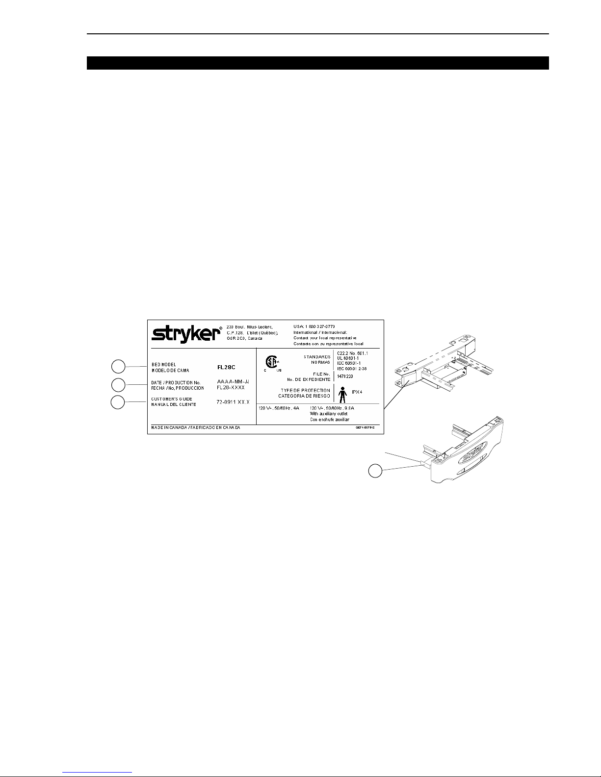
Contact the Technical Service department (see section 1.2) or your local representative and
provide the following information that can be found on the serial number plate and the
manufacturer's nameplate affixed respectively to the right side of the frame at the foot end of the
bed, and on the right side of the head end casing:
HEAD END
B
C
D
MANUFACTURER NAMEPLATE
SERIAL NUMBER PLATE
FOOT END
Figure 1.5
• From the serial plate, write down the serial number (A).
• From the manufacturer's nameplate, write down the bed model (B), the production number
(C), ex. FL28-XXXX, and the Customer's Guide number (D).
• Consult the parts lists and the drawings contained in the Customer Guide third section,
“Parts Lists”, to identify the defective part. Write down the information.
• Write down a description of the problem encountered while using the equipment.
E
NNOOTTE
It is very important that you refer to the parts lists and drawings of the Parts Lists manual
specific to the bed needing repair.
The Technical Service representative can help you identify the parts to be replaced. However, if
an error occurs when ordering, the user remains responsible for the parts ordered.
Stryker will take back wrong parts ordered but will not assume shipping charges, and restocking
fees will be charged to the user unless a Field Service Representative has been requested for
an on-site diagnosis of the malfunction.
7
Page 8
Maintenance Manual
A
RETURN AUTHORIZATION
Merchandise cannot be returned without approval from the Technical Service department. An
authorization number will be provided, which must be clearly printed on the returned
merchandise. Stryker reserves the right to charge shipping and restocking fees on returned
items.
DAMAGED ME R CHANDISE
Claims for damaged merchandise must be made with the carrier within fifteen (15) days of
receipt of merchandise. DO NOT ACCEPT DAMAGED SHIPMENTS UNLESS SUCH DAMAGE
IS NOTED ON THE DELIVERY RECEIPT AT THE TIME OF RECEIPT. Upon prompt
notification, Stryker will file a freight claim with the appropriate carrier for damages incurred.
Claims will be limited in amount to the actual replacement cost. In the event that this information
is not received by Stryker within the fifteen (15) day period following the delivery of the
merchandise, or the damage was not noted on the delivery notice at the time of receipt, the
customer will be responsible for payment of the original invoice in full.
Claims for any short shipment must be made within five (5) days of invoice.
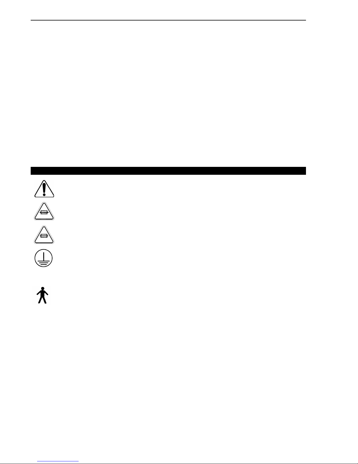
1.6 SYMBOLS
Warning, refer to accompanying documents
Fuse rating for 100V∼ and 120V∼ electric systems
10A 250V
Fuse rating for 200V∼, 220V∼ and 240V∼ electric
6.3A 250V
systems
Protective Earth (ground)
∼
lternating Current
Type B Equipment
IPX4 Protection from liquid splash
8
Page 9

Pr eventative Maintenance Chapter 2
A
A
2. PREVENTATIVE MAINTENANCE
2.1 BED CLEANING AND MATTRESS CARE
WWAARRNNIINNGG
When large fluid spills occur in the area of the circuit boards, cables and motors, immediately
unplug the bed power cord from the wall outlet, remove the patient from the bed and clean up
the fluid. Have maintenance completely check the bed. Fluids can have an adverse effect on
operational capabilities of any electrical product. DO NOT put the bed back into service until it is
completely dried and has been thoroughly tested for safe operation. Ensure, among other
things, that the plastic components being used as covers for the siderail mechanism arms and
the foot end casing are removed and that the parts they cover are thoroughly dried.
C
C
UUTTIIOON
N
Do not use harsh cleaners, solvents or detergents. Equipment damage could occur. Do not
steam clean, hose off or ultrasonically clean the bed. Do not immerse any part of the bed. The
bed electrical parts may be damaged by exposure to water.
Germicidal disinfectant, used as directed, and/or Chlorine Bleach products are not considered
mild detergents. These products are corrosive in nature and may cause damage to your bed if
used improperly. If these types of products are used, ensure the beds are wiped with clean
water and thoroughly dried following cleaning. Failure to properly rinse and dry the beds will
leave a corrosive residue on the surface of the bed, possibly causing premature corrosion of
critical components. Failure to follow the above directions when using these types of cleaners
may void this product warranty.
CLEANING BEDS
Hand wash all surfaces of the bed with a soft cloth moistened with a solution of lukewarm water
and a mild detergent.
Wipe the bed clean and dry thoroughly to avoid build up of cleaning solution.
MATTRESS CARE
WWAARRNNIINNGG
Inspect the mattress after each use. Discontinue use if any cracks or rips, which may allow fluid
to enter the mattress, are found in the mattress cover. Failure to properly clean the mattress, or
dispose of it if defective, may increase the risk of exposure to pathogenic substances and
bring about diseases to the
patient and user.
may
• Inspection
Implement local policies to address regular care, maintenance, and cleaning of mattresses and
covers. The cover cleaning procedure can be found below and on the bed label.
Inspect the mattress cover inner and outer surfaces and the zip fasteners regularly for signs of
damage. If the mattress cover is heavily stained or soiled, or is torn, remove the mattress from
service.
• Cleaning
Stains: Wash with lukewarm water using a mild detergent. Rinse with water and let dry. For
tough stains, use bleach diluted with ten parts of water.
9
Page 10
Maintenance Manual
A
A
A
2.2 LUBRICATION REQUIREMENTS
The only components of the bed needing periodic verification and lubrication are the four
actuator screws and the clevis pin holding the head actuator to the head section lever. They
should be checked every year and lubricated every two years.
C
C
UUTTIIOON
N
The bed uses oil-impregnated shoulder spacers at hinge points. Do not lubricate these shoulder
spacers. When shoulder spacers are found worn, replace them.
ACTUATOR SCREW LUBRICATION
Required Tools:
No. 2 Phillips Screwdriver 1/4" Ratchet (w/6" extension) and 5/16" socket
OG2 Grease Brush Bung ee Cord
Procedure:
B
Clevis Pin
1. Raise the bed fully up and apply the brakes.
2. Remove if applicable the head section plastic cover (optional).
3. Fully raise the head section.
4. Remove the head board.
5. Unplug the bed power cord from the wall outlet.
6. Apply grease all over the clevis pin.
7. Fully raise and lower the head section several times to spread the grease.
10
B
Figure 2.2
Page 11

Pr eventative Maintenance Chapter 2
Head and Thigh Actuators
8. Raise the bed fully up and apply the brakes.
9. Remove if applicable the head and foot section plastic covers (optional).
10. Fully raise the head section and flatten the thigh section. Lower the four siderails.
11. Unplug the bed power cord from the wall outlet.
12. Lift and fold back the foot section toward the head end of the bed. Secure the foot section to
the bed using a bungee cord.
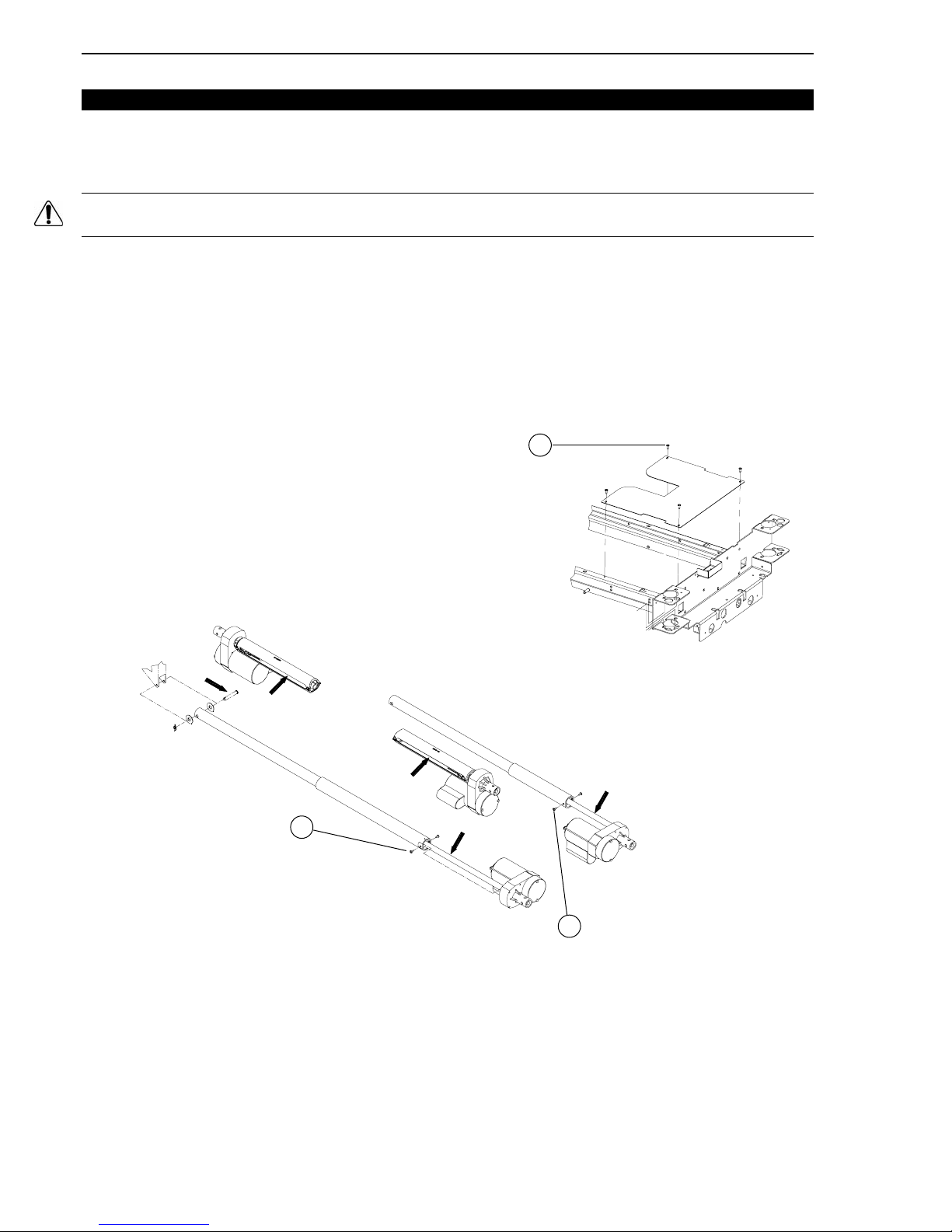
13. Using a no. 2 Phillips screwdriver, remove the four screws (A) holding the cover plate to the
frame and remove the plate. Remove the optional night light if present.
14. Using a 1/4" ratchet (w/6" extension) and a 5/16" socket, remove the two screws (B) holding
the dust tube of each actuator. Push the tube back to uncover the screw threads.
15. Using a brush, apply grease on the screw threads. Make sure the grease reaches the
bottom of the threads.
16. Replace the dust tubes.
17. Replace the cover plate.
18. Lower the foot section.
19. Plug in the bed power cord and, using the electric controls, raise and lower several times the
Fowler and Knee Gatch to spread the grease evenly.
Hi-Lo Actuators
1. Lower the bed completely and apply the brakes. Flatten the mattress support.
2. Lower the four siderails.
3. Remove if applicable the head and foot section plastic covers (optional), to reach the Hi-Lo
actuators. Otherwise, fully raise the head section, and lift and fold back the foot section
toward the head end of the bed. Secure the foot section to the bed using a bungee cord.
4. Unplug the bed power cord from the wall outlet
5. Using a brush, apply grease on the threads through the dust tube side openings of both HiLo actuators. Make sure the grease reaches the bottom of the threads.
6. Lower the foot section.
7. Plug in the bed power cord and, using the electric controls, raise and lower the bed several
times to spread the grease evenly.
11
Page 12

Maintenance Manual
A
A
2.3 PREVENTATIVE MAINTENANCE PROGRAM
W
W
RRNNIINNG
G
When servicing use only identical replacement parts provided by Stryker.
ANNUAL CHECKLIST
⎯ All fasteners secure.
⎯ Inspect for excessive wear the oil-impregnated bronze shoulder spacers found at the bed
hinge points. Do not lubricate these spacers. Replace as needed.
⎯ Check the grease present on the components detailed in section 2.2, lubricate if needed
(see section 2.2). Lubricate them at least every two years.
⎯ On both sides of the bed, depress fully down the side of the pedal identified with a red
sticker and ensure that the brakes are applied and the bed is immobilized. Toggle the pedal
to neutral and ensure the brakes are released.
⎯ On both sides of the bed, depress fully down the side of the pedal identified with a green
sticker and ensure that the steer wheel is engaged. Toggle the pedal to neutral and ensure
that the steer wheel disengages.
⎯ Siderails move, latch and stow properly.
⎯ All controls of the foot end panel working properly, including LED's.
⎯ Calibrate the scale (optional). Refer to the scale calibration procedure on page 41.
⎯ All siderail controls working properly.
⎯ Ensure that the nurse call (optional) alarm sounds in the nurse station.
⎯ Verify the CPR emergency release (optional) using both CPR release handles: raise the
Fowler fully up and, using the CPR handle, lower the Fowler gradually to flat position by
pulling, holding and releasing the handle several times. Ensure the Knee Gatch (if raised)
also starts flattening when the Fowler is completely down. Following the complete lowering
of the Fowler, wait approximately 30 seconds - the time for the Fowler actuator to reset - and
verify that the actuator has indeed reset itself by raising the Fowler fully up.
⎯ Verify the Fowler, Knee Gatch and Hi-lo movements to ensure that the motion interrupt
switch integrated to the four electric actuators is operating properly.
⎯ Auxiliary outlet (option available only with 120V beds) working properly.
⎯ Night light (optional) working properly.
⎯ No cracks in the boards, siderails, wheel covers, steer wheel hood (optional) and plastic
covers (optional) of the head and foot sections.
⎯ Head end bumpers tightly secured to frame and working properly.
⎯ No rips or cracks in mattress cover. Replace if so.
⎯ Power cord intact.
⎯ No cables pinched or worn.
⎯ All electrical connections tight.
⎯ All grounds secure to the frame.
⎯ All casters roll properly. Check caster for cuts, wear, etc.
⎯ Measure current leakage and grounding continuity of the bed and the auxiliary outlet
(optional). Check with our Technical Service (see section 1.2) for the acceptable values.
12
Page 13

Pr eventative Maintenance Chapter 2
RECOMMENDED SPARE PARTS
The following is a list of recommended on hand spare parts for the FL28C bed.
Description Part Number Parts List
• Electric/Electronic Components
Motor Control Board QDF23-0315 OL280116/117
Scale Control Board (Optional) QDF28-0265 OL280005
S.A. Scale Display (Optional) QDF28-0266 OP280001/002
/003
Nurse Call Control Board (Optional) QDF20-0126 OL280024
Nurse Call (optional) / Gen lll (optional) Control Board QDF20-0121 OL280035
Micro Switch 1325P003 OL280031
Push Button Micro Switch QDF9159 OL280031
Power Connector 23-0267 OL280116/117
Fuse - Fast Acting 10A, 250V for 100/120V Electric Systems QDF8078 OL280116/015
Fuse - Slow Blow 6.3A, 250V for 200/220/240V Electric Systems QDF8068 OL280016/017
/018
Power Cord with Straight N A Molded Plug QDF8066 OL250053
Power Cord with 90° N A Molded Plug (Optional) QDF8066-90D OL250055
Foot Board/Control Board Cable QDF28-0259 OL28116/117
Speakerphone w/Connectors (Optional) QDF26-0111 OL280026
Night Light (Optional) QDF9539 OL250018
Load Cell w/Long Cable QDF14-1367 OL280005
Load Cell w/Short Cable QDF25-0218 OL280005
Auxiliary Power Outlet (Optional) QDF8024 OL250029
5A Circuit Breaker (for Optional Auxiliary Power Outlet) QDF9025 OL250029
Hi-Lo Actuator 28-0760 OL280116/117
Head Section Actuator 28-0761L OL280116/117
Thigh Section Actuator 28-0762 OL280116/117
Toroidal Transformer (International Series Bed) QDF14-1160 OL280117
Stand Off Pins: Motor Control Board
Stand Off Pins: Scale Control Board (Optional)
QP23-0258
QDF8011
OL280116/117
OL280005
Strain Relief Bushing QDF9541 OL280116/117
Female Screw Lock QDF2047
• Foot Board Components
Round Self-Sticking Screw Cover QDF28-0334 L28-015
• Siderail Components
"Lift To Release" Self-Sticking Sticker QDF28-0146 L28-012/002
Oblong Self-Sticking Screw Cover QDF28-0145 L28-012/002
• Mattress Support Components
Head Section Plastic Cover (optional) 28-0101 OL280032
Foot Section Plastic Cover (optional) 28-0103 OL280032
Steel Head Section (Optional) 28-0197L OL280007
Steel Foot Section (Optional) 28-0196L OL280007
13
Page 14

Maintenance Manual
Seat Section 28-0345L OL280032
Thigh section 28-0034L OL280032
CPR Mechanism Long Cable (Optional) QDF19-0815 OL280034
CPR Mechanism Short Cable (Optional) QDF19-0354 OL280034
CPR Mechanism Pneumatic Cylinder (Optional) QDF5090 OL280034
Foot End Mattress Retainer 17-0211L OL250022/023
• Hi-Lo Mechanism Components
Right "Stub-Acme" Nut QP13-0677-05 OL280116/117
Nut Support QPA25-0380 OL280116/117
• Base Components
Foot End Casing Plastic Cover QP28-0111 L28-005
Plastic Base Tube Cover QP25-0023 L28-020
6" Caster w/Locking Mechanism R25-0388-13 OL280003
5th Steer Wheel RL5 L28-006
Right Wheel Cover QP28-0299-13 L28-020
Left Wheel Cover QP28-0300-13 L28-0 20
Brake/Steer Pedal QP28-0130-13 L28-006
• Miscellaneous
OG2 Grease M0027
Touch-Up Paint - Opal PD018
Ty-rap Q DF9518
Nylon Cable Dia. 3/4" QDF9532
Coupling for Ty-rap QDF9533
14
Page 15

Troubleshooting Chapter 3
3. TROUBLESHOOTING
Please consult the following troubleshooting guide before calling the Technical Service department
(see section 1.2).
3.1 TROUBLESHOOTING GUID E
PROBLEM/FAILURE WHAT TO CHECK
No power to bed
• Is the power cord connected to the power
connector and plugged into the wall outlet?
• Is the bed power switch at the head end of
the bed turned on?
• Is the power cord severed? Replace if
needed.
• Are the two fuses inside the power
connector still operational (see page 37)?
• Verify power at wall outlet.
No bed up or down motion when:
• the siderail command is used
• the foot board command is used
No Fowler up or down motion when:
• the siderail command is used
• the foot board command is used
The Fowler does not fully raise
• Is the total lockout activated (LED (padlock)
on)? If so, deactivate it.
• Is the cable of the siderail control panel
properly connected to the bed receptacle
under the mattress support?
• Check points of the “No power to bed”
problem described above.
• Is the Fowler lockout activated (LED
(padlock) on)? If so, deactivate it.
• Is the total lockout activated (LED (padlock)
on)? If so, deactivate it.
• Is the cable of the siderail control panel
properly connected to the bed connector
under the mattress support?
• Check points of the “No power to bed”
problem described above.
This situation happens when the CPR handle
is used to partly lower the Fowler. The use of
the CPR mechanism for this purpose creates a
situation where the Fowler motor is out of sync
with the actual position of the Fowler. To
correct the situation:
• Completely lower the Fowler using the
CPR handle or the Fowler down control to
enable the Fowler motor to reset itself.
Refer to the "Emergency CPR Release"
section of the Operations Manual for more
information.
15
Page 16

Maintenance Manual
No Knee Gatch up or down motion when:
• the siderail command is used
• the foot board command is used
No Auto Contour motion (optional))
Improper operation of the CPR positioning
(optional): Knee Gatch does not lower and/or
the Fowler actuator does not reset.
The weight shown on the scale display
(optional) is incorrect.
Scale display (optional) reads OVERLOAD or
shows incorrect weight.
Angle shown on the scale display (optional) is
incorrect
• Is the Knee Gatch lockout activated (LED
(padlock) on)? If so, deactivate it.
• Is the total lockout activated (LED (padlock)
on)? If so, deactivate it.
• Is the cable of the siderail control panel
properly connected to the bed connector
under the mattress support?
• Check points of the “No power to bed”
problem described above.
• Is the Knee Gatch or total lockout activated
(LED (padlock) on)? If so, deactivate it.
• Check and replace if needed the two Auto
Contour limit switches (see page 44).
• Check and replace if needed (see pages
46 and 47) the two CPR limit switches.
• Zero the bed without the patient in it (see
the "Scale System Usage" section in the
Operations Manual).
• Calibrate the scale (see page 41).
• The weight present on the bed is superior
to the scale capacity, which is 500 lb (227
kg). If the patient weight is superior to 500
lb (227 kg), do not use the scale.
If not the case, zero the scale after having
removed the patient from the bed. This
situation often results from equipment
added to the bed without using the
add/remove equipment procedure (see the
Operations Manual). The weight of this
equipment is then added to the patient's
weight.
• One or more load cell cable not properly
connected or completely disconnected from
the scale control board (see figure 4.3E,
page 38 for the connecting positions of the
load cell cable).
• Calibrate the scale (see page 41).
16
Page 17

Troubleshooting Chapter 3
Scale display (optional) does not turn on when
the scale is activated.
Scale (optional) displays "No scale found".
All lockout LEDs (padlock icons) flash or the
word Error appears at the bottom of the LCD
display.
• Press ENTER key twice.
• Turn the main power switch off and turn it
on.
• Lift the foot board and gently replace it into
position taking care to completely push it
down so that the connectors match
correctly.
• Check points of the “No power to bed”
problem described above.
• Scale user interface cable not properly
connected or completely disconnected from
the scale control board (J6 connector, see
drawing L28-008 in the parts list manual).
• Press the ENTER key. If message
persists, contact our Technical Service
(see section 1.2).
If message disappears, data displayed is
correct and current procedure can be
resumed.
• The scale is unable to measure the
weight due to an electrical problem.
Please contact our Technical Service
(see section 1.2).
Bed Exit system (optional) does not operate
properly.
Bed Exit system (optional) does not work at all
or alarm goes off when Bed Exit is activated.
Nurse call (optional) or Bed Exit (optional)
signal does not reach the nurse desk.
• Verify that the load cell cables are properly
connected to the scale control board (see
figure 4.3E, page 38 for the illustration of
the load cell cable connecting positions).
• Check points of the “No power to bed”
problem described above.
• One or more load cell cable are not
properly connected or are completely
disconnected from the scale control board
(see figure 4.3E, page 38 for the load cell
cable connecting positions).
• Check points of the “No power to bed”
problem described above.
• Check the connecting cable.
• Check the wall outlet.
• Contact the Technical Service (see 1.2)
17
Page 18
Maintenance Manual
A
A
4. MAINTENANCE PROCEDURES
WWAARRNNIINNGG
Only field technicians from Stryker or service personnel trained by Stryker should perform the
procedures detailed in this maintenance manual, especially those related to the Scale (option)
and Bed Exit (option) systems. Failure to observe this restriction can result in serious damage to
material and/or severe injury to people.
To prevent injury when working under the bed with the bed in the high position, always place
blocks under the mattress support frame and apply the brakes.
Always unplug the bed power cord from the wall outlet when servicing or cleaning the bed.
NOTE
Throughout this maintenance manual, the words “right” and “left” refer to the right and left sides
of a patient lying face up on the bed.
4.1 SIDERAIL MAINTENANCE PROCEDURES
HEAD SIDERAIL ASSEMBLY REPLACEME NT
Required Tools:
1/2" Wrench 3/16" Allen Key Cutting Pliers
Procedure:
B
B
Figure 4.1
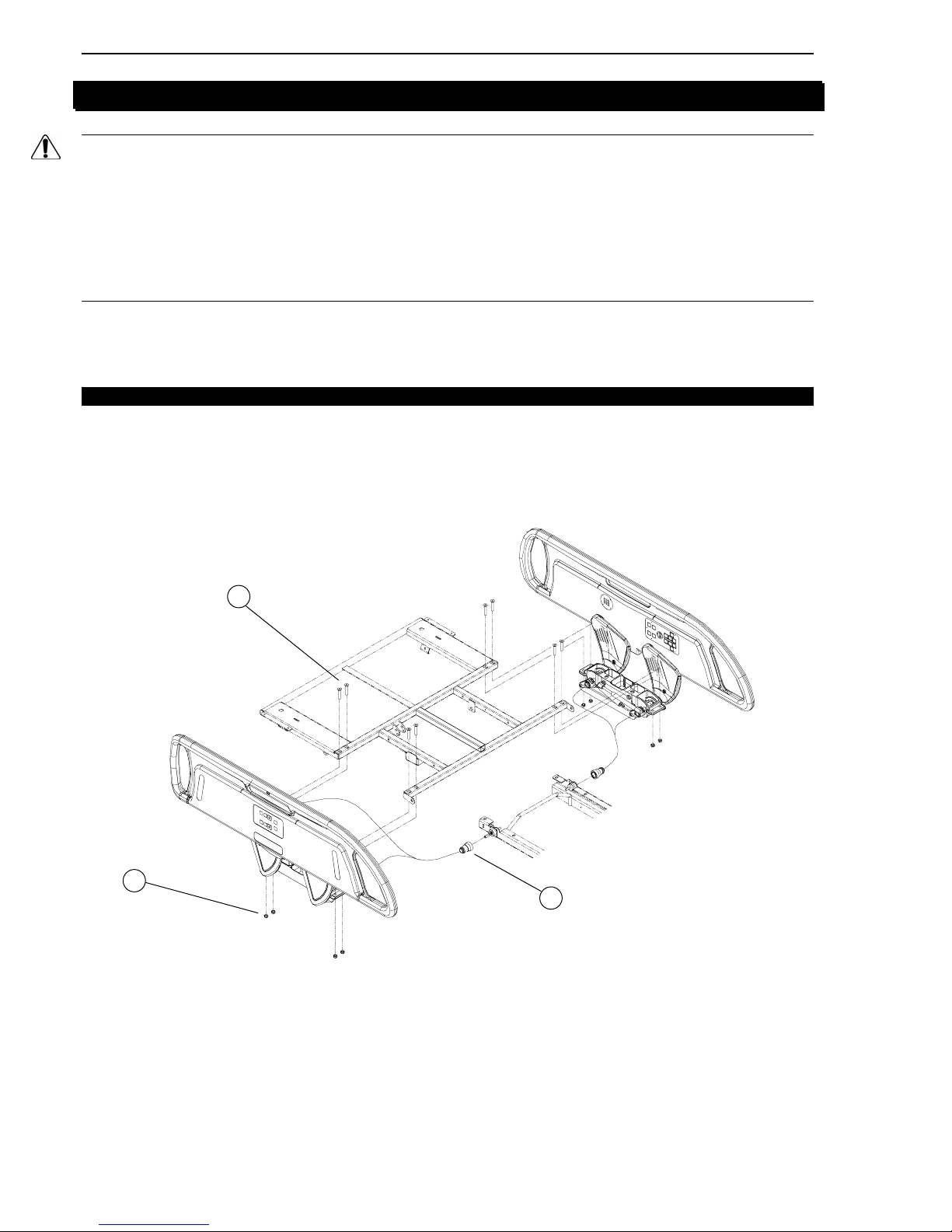
1. Run the bed fully up and apply the brakes.
2. Remove the head section plastic cover (optional). Fully raise the head section and raise the
siderail needing repair.
3. Unplug the power cord from the wall receptacle.
4. Loosen the lock ring (A) and unplug the siderail cable.
5. Using cutting pliers, remove the Ty-raps holding the siderail cable to the frame.
6. Using a 3/16" Allen key and a 1/2" wrench, remove the four locknuts/bolts (B) holding the
siderail assembly to the head section and remove the assembly. Support the assembly
when removing the last bolts.
18
Page 19

Mai ntenance Procedures Chapter 4
A A
7. Reverse the above steps to install the new siderail assembly.
8. Test the siderail movement and all controls of both control panels, including the nurse call
optional) and the communications package (optional), for proper operation before returning
the bed to service.
HEAD RAIL REPLACEMENT
Please contact the Technical Service (see section 1.2) for information regarding the
replacement of a head end rail.
HEAD SIDERAIL MECHANISM REPLACEMENT
Please contact the Technical Service (see section 1.2) for information regarding the
replacement of a head end siderail mechanism.
FOOT SIDERAIL ASSEMBLY REPLACEMENT
Required Tools:
1/2" Socket Wrench 1/2" Wrench Bungee Cord
Procedure:
K
G
F
D
B
C
B
E
Figure 4.1B
1. Run the bed fully up and apply the brakes. Raise the siderail needing repair.
2. Run the Knee Gatch fully up and unplug the power cord from the wall receptacle.
3. Remove if applicable the foot section plastic cover (optional). Lift and fold the foot section
back toward the head end of the bed. Secure its position using a bungee cord.
4. Using a 1/2" socket wrench and a 1/2" wrench, remove the four locknuts/bolts (A) holding
the siderail assembly to the support and remove the assembly. Support the siderail
assembly while removing the last bolts.
5. Reverse the above steps to install the new siderail assembly.
6. Test the siderail for proper operation before returning the bed to service.
K
19
Page 20

Maintenance Manual
FOOT RAIL REPLACEMENT
Required Tools:
Small Slotted Head Screwdriver No. 2 Phillips Screwdriver 5/32" Allen Key
Bungee Cord
Procedure:
E
NNOOTTE
Unless otherwise indicated, refer to figure 4.1B on page 19 for the illustration of this procedure
reference points.
1. Run the bed fully up and apply the brakes. Raise the siderail needing repair.
Unplug the bed power cord from the wall outlet.
2.
Using a small slotted head screwdriver, lift and remove the following self-sticking parts: the
3.
three screw-covers (B) and the "Lift to release siderail" label (C) to expose the screws
holding the siderail cover. Proceed gently when inserting the screwdriver under the labels to
avoid scratching the molded rail.
E
NNOOTTE
Do not reuse the self-sticking parts removed since their self-adhesive coating considerably
looses its efficiency once they are removed. Replace them with new parts.
4. Using a no. 2 Phillips screwdriver, remove the eight screws (D) holding the cover to the
siderail and remove the cover.
WAARRNNIINNGG
W
The eight screws (D) must be replaced with new identical screws because their Scotch-Grip
coating is less efficient once they have been tightened and removed thereafter.
5. Remove the yellow locking lever (E).
Using a no. 2 Phillips screwdriver, remove the screw (F) holding each siderail arm plastic
6.
cover and lift up the covers to remove them.
Using a 5/32" Allen key, remove the two Allen screws (G) holding each pommel to the
7.
siderail arms. Leave one loosened screw on each pommel until ready to remove both
pommels.
While supporting the rail, remove the two last screws, the pommels, the bungee cord and
8.
finally the rail.
E
NNOOTTE
Note the position of the pommel with the lock (left pommel when facing the rail) when the
siderail is fully raised. The rail will not lock in high position if this pommel is positioned
differently.
Reverse the above steps to install the new rail.
9.
Test the siderail for proper operation before returning the bed to service.
10.
FOOT SIDERAIL MECHANISM REPLACEMENT
Required Tools:
Small Slotted Head Screwdriver No. 2 Phillips Screwdriver 5/32" Allen Key
Bungee Cord 1/2" Socket Wrench 1/2" Wrench
Procedure:
1. Follow steps 1 to 8 of the foot end rail replacement procedure above.
2. Using a 1/2" socket wrench and a 1/2" wrench, remove the four locknuts/bolts (K, fig. 4.1B,
page 19) holding the mechanism assembly to the support and remove the assembly.
3. Reverse the above steps to install the new mechanism assembly.
4. Test the siderail for proper operation before returning the bed to service.
20
Page 21

Mai ntenance Procedures Chapter 4
A
SIDERAI L OUTER PANEL MEMBRANE REPLACEMENT
Required Tools:
Small Slotted Head Screwdriver No. 2 Phillips Screwdriver
Procedure:
G
I
H
F
D
C
B
C
D
E
H
Figure 4.1C
1. Run the bed fully up and apply the brakes. Raise the siderail needing repair.
2. Unplug the bed power cord from the wall outlet.
3. Using a small slotted head screwdriver, lift and remove the following self-sticking parts: the
outer membrane (A), the two screws covers (B) and the "Lift to release siderail" sticker (C)
to expose the screws holding the siderail cover. Proceed gently when inserting the
screwdriver under the stickers to avoid damaging the cover.
E
NNOOTTE
Do not reuse the self-sticking parts removed since their self-adhesive coating considerably
looses its efficiency once they are removed. Replace them with new parts.
4. Using a Phillips screwdriver, remove the eight screws (D) holding the cover to the siderail
and remove the cover.
WAARRNNIINNGG
W
The eight screws (D) must be replaced with new identical screws because their Scotch-Grip
coating is less efficient once they have been tightened and removed thereafter.
5. Disconnect the defective membrane and remove it.
6. Reverse the above steps to install the new membrane.
7. Test all controls of the control panel for proper operation before reassembling the siderail
and returning the bed to service.
21
Page 22

Maintenance Manual
SPEAKERPHONE/SIDE RA I L INNER PANEL MEMBRANE REPLACE ME NT
Required Tools:
Small Slotted Head Screwdriver No. 2 and 3 Phillips Screwdrivers Cutting Pliers
Bungee Cord 5/32" Allen Key
Procedure:
E
NNOOTTE
Unless otherwise indicated, refer to figure 4.1C on page 21 for the illustration of this procedure
reference points.
1. Follow steps 1 to 4 of the "Siderail Outer Panel Membrane Replacement" procedure
described on page 21.
2. Secure the siderail needing repair to the adjacent
siderail using a bungee cord (see opposite
illustration).
3. Using side cutters, clip the lower cable tie (E)
holding the bottom part of the grey cable (there
may be two cables) to the aluminum structure. The
loose given to the cable will be necessary for steps
to come.
E
NNOOTTE
Make sure the cable ties are inserted in the aluminum
structure before reinstalling the structure.
4. Using a no. 2 Phillips screwdriver, remove the
screw (F) holding each siderail arm cover and lift
up the covers to remove them.
5.
Using a 5/16" Allen key, remove the two Allen screws (G) holding each pommel to the
siderail arms. Leave one loosened screw on each pommel until ready to remove both
pommels.
6. While supporting the rail, remove the two last screws and the bungee cord.
7. Lift the siderail, pass it over the mechanism arms and lay it on the mattress support while
gently pulling on the cables.
8. Using a no. 3 Phillips screwdriver, remove the six screws (J) holding the aluminum structure
to the siderail.
E
NNOOTTE
Do not reuse these Scotch-Grip screws. Replace them with new screws (P/N VV37A1N24).
9. Grasp and lift the upper part of the aluminum structure until it may be secured temporarily to
one of the mechanism arms using a cable tie.
To replace the speakerphone, proceed with step 10 to 13 and end the procedure.
To replace the inner panel membrane, proceed with step 14 to 17 and end the procedure.
10. Remove the cables connected to the speakerphone. Note their position before removing
them.
11. Using a no. 2 Phillips screwdriver, remove the four screws (I) holding the speakerphone to
the siderail and remove it.
12. Reverse the preceding steps to install the new speakerphone.
E
NNOOTTE
Before reassembling the different parts of the siderail, we recommend that you check the
continuity at the speakerphone terminals to ensure the circuit operates properly.
13. Test the nurse call and all controls of the inner and outer control panels for proper operation
before reassembling the siderail and returning the bed to service.
22
Page 23

Maintenance Procedures Chapter 4
End of procedure
14. Disconnect the inner membrane connector.
15. Using a small slotted head screwdriver, lift and remove the inner membrane. Proceed gently
when inserting the screwdriver under the membrane to avoid scratching the plastic cover.
16. Connect and install the new membrane.
17. Test the siderail inner and outer controls for proper operation before reassembling the
siderail and returning the bed to service.
23
Page 24

Maintenance Manual
A
4.2 FOOT BOARD MAINTENANCE PROCEDURES
FOOT END CO NTROL PANEL MEMBRANE REPLACEMENT
Required Tools:
Small Slotted Head Screwdriver No. 2 Phillips Screwdriver
Procedure:
B
C
D
C
Figure 4.2
1. Run the bed fully up and apply the brakes.
2. Unplug the bed power cord from the wall outlet.
3. Using a small slotted head screwdriver, lift and remove the five self-sticking round screwcovers (A) located on the foot board cover as well as the self-sticking membrane (B) of the
foot board control panel to expose the screws holding the cover to the foot board.
E
NNOOTTE
Do not reuse the self-sticking parts removed since their self-adhesive coating considerably
looses its efficiency once they are removed. Replace them with new parts.
4. Properly ground yourself (see section 1.4).
5. Using a no. 2 Phillips screwdriver, remove the seven screws (C) holding the cover to the foot
board and remove the cover after having removed the cables connected to it. Note the cable
positions in order to replace them properly.
6. Remove the defective membrane.
7. Reverse the above steps to install the new membrane.
E
NNOOTTE
Be careful not to stick the cable to the back of the membrane.
8. Test all the functions of the foot end control panel before returning the bed to service.
24
Page 25

Maintenance Procedures Chapter 4
SCALE SYSTEM LCD DISPLAY REPLACEMENT (OPTIONAL)
Required Tools:
Small Slotted Head Screwdriver No. 2 Phillips Screwdriver
Procedure:
E
NNOOTTE
Unless otherwise indicated, refer to figure 4.2 on page 24 for the illustration of this procedure
reference points.
1. Run the bed fully up and apply the brakes.
2. Unplug the bed power cord from the wall outlet.
3. Using a small slotted head screwdriver, lift and remove the five self-sticking round screwcovers (B) located on the foot board cover as well as the self-sticking membrane (A) of the
foot board control panel to expose the screws holding the cover to the foot board.
E
NNOOTTE
Do not reuse the self-sticking parts removed since their adhesive coating considerably looses its
efficiency once they are removed. Replace them with new parts.
4. Properly ground yourself (see section 1.4).
5. Using a no. 2 Phillips screwdriver, remove the seven screws (C) holding the cover to the foot
board and remove the cover after having removed the cables connected to it. Note the cable
positions in order to replace them properly.
6. Using a small slotted head screwdriver, push aside the clips (D) and remove the LCD
display (E) after having disconnected its cable.
7. Reverse the above steps to install the new LCD display.
8. Test the LCD display for proper operation before replacing the foot board cover and
returning the bed to service.
25
Page 26

Maintenance Manual
A
4.3 MATTRESS SUPPORT MAINTENANCE PROCEDURES
FOOT SECTION REPLACEMENT
Required Tools:
1/2" Wrench No. 2 Phillips Screwdriver Bungee Cord
Procedure:
F
E
C
H
B
G
D
E
Figure 4.3A
1. Run the bed fully up and apply the brakes. Flatten all sections of the mattress support.
2. Unplug the bed power cord from the wall outlet.
3. Lower the siderails.
4. Remove if applicable the foot section plastic cover (optional). Lift and fold back the foot
section toward the head end of the bed and secure it to the bed using a bungee cord.
5. Remove the foot end mattress retainer (A) and install it on the new foot section. Replace the
foot section to horizontal position,
6. Using a 1/2" wrench, remove the two locknuts/washers/shoulder spacers/bolts (B) linking
the foot section to the thigh section and remove the defective section.
7. Reverse the above steps to install the new foot section.
26
Page 27

Maintenance Procedures Chapter 4
THIGH SECTION REPLACEMENT
Required Tools:
Long Nose Pliers 1/2" wrench No. 2 Phillips Screwdriver
Procedure:
E
NNOOTTE
Unless otherwise indicated, refer to figure 4.3A on page 26 for the illustration of this procedure
reference points.
1. Run the bed fully up and apply the brakes. Flatten all sections of the mattress support.
2. Unplug the bed power cord from the wall outlet.
3. Raise the siderails.
4. Using long nose pliers, remove the rue ring cotter/washers/clevis pin (E fig. 4.3B, page 30)
linking the thigh section lever arms to the thigh actuator tube.
5. Using a 1/2" wrench, remove the four locknuts/washers/shoulder spacers/bolts (B, C) linking
the thigh section to the foot and seat sections.
6. Remove the defective thigh section and lay it upside down on a workbench.
7. Using a no. 2 Phillips screwdriver, remove the two screws (D) holding the micro switch
activator to the thigh section. Install the activator on the new thigh section.
8. Reverse the above steps to install the new thigh section.
9. Test the Knee Gatch as well as the Auto Contour positioning (optional) before returning the
bed to service.
E
NNOOTTE
Should Auto Contour not perform properly, check the positioning of the switch activator on the
thigh section.
SEAT SECTION REPLACEMENT
Required Tools:
1/2" Long Socket Wrench Two 1/2" Wrench No. 2 Phillips Screwdriver
Procedure:
E
NNOOTTE
Unless otherwise indicated, refer to figure 4.3A on page 26 for the illustration of this procedure
reference points.
1. Raise the bed fully up and apply the brakes. Flatten the mattress support.
2. Unplug the power plug from the wall outlet.
3. Lower the siderails.
4. Using two 1/2" wrench, remove the locknut/shoulder spacers/bolt holding the mattress
support lever of the CPR mechanism (N, fig. 4.3H, page 46) to the seat section.
5. Using a 1/2" long socket wrench and a 1/2" wrench, remove the four locknuts/washers/bolts
(E) holding the seat section to the frame.
6. Using a 1/2" wrench, remove the four locknuts/washers/shoulder spacers/bolts (C, F) linking
the seat section to the thigh and head section and remove the defective seat section.
7. Using a no. 2 Phillips screwdriver, remove the three screws (G) holding the protective plate
to the seat section.
8. Reverse the preceding steps to install the new seat section.
27
Page 28

Maintenance Manual
HEAD SECTION REPLACE MENT
Required Tools:
1/2" Socket Wrench Two 1/2" Wrenches No. 2 Phillips Screwdriver
3/16" Allen Key 7/16" Wrench Strap
Procedure:
E
NNOOTTE
Unless otherwise indicated, refer to figure 4.3A on page 26 for the illustration of this procedure
reference points.
WWAARRNNIINNG
G
Under no circumstances should the CPR emergency release (optional) handles be activated
during this procedure or serious injury to people or damage to equipment could occur.
1. Fully raise the bed and apply the brakes.
2. Unplug the bed power cord from the wall outlet.
3. Raise the head siderails.
4. Remove if applicable the head section plastic cover (optional) or run fully up the head
section. Secure the head section to the bed using a strap to prevent the head section from
moving during the procedure.
5. Loosen the lock rings (A, fig. 4.1A, page 18) of both siderail cables and remove the siderail
cables. Using cutting pliers, cut the Ty-raps holding the siderail cables to the frame.
6. Using a 3/16" Allen key and a 1/2" wrench, remove the four locknuts/bolts (B, fig. 4.1A, page
18) holding each head siderail assembly to the head section and remove the siderails.
7. Using a no. 2 Phillips screwdriver, remove the screw holding each cable tie present on both
sides of the head section structure.
8. Using a 1/2" wrench, remove the nuts/shoulder spacers/bolts (H) holding the head section to
the stabilizer arms. Lay the stabilizer arms down.
If the bed is equipped with the CPR mechanism, proceed with step 9 to 16 and end the
procedure.
If not, proceed with step 17 to 21 and end the procedure.
9. Remove the two wires (C, fig, 4.3H, page 46) from the micro switch. Note their position
before removing them.
10. Using two 1/2" wrench, remove the locknut/shoulder spacers/bolt (L, fig. 4.3H, page 46)
holding each CPR handle to the head section. To remove the cable ends from the handle
slots, loosen the two locknuts holding each CPR cable to its handle using a 7/16" wrench.
E
NNOOTTE
Insert the cable ends inside the handle slots before assembling the handle to the new head
section. Then adjust the two locknuts of each cable in order to have a 1/8" play in the CPR
handle movement.
11. Using two 1/2" wrenches, remove the locknut/bolt (M, fig. 4.3H, page 46) holding the
pneumatic cylinder end fitting to the head section lever arms. Lay the CPR mechanism
down on the frame.
12. Remove the strap and lower the head section while holding it firmly.
13. Using a 1/2" wrench, remove the two locknuts/shoulder spacers/bolts (F) holding the head
section to the seat section.
14. Remove from the defective head section the micro-switch by pressing its two side clips
15. Reverse the above steps to install the new head section.
16. Test the head section and CPR mechanism for proper operation before returning the bed to
service.
End of procedure.
28
Page 29

Maintenance Procedures Chapter 4
A
B
Figure 4.3AA
17. Using two 1/2" wrenches, remove the locknut/bolt (A) holding the lever to the head section,
lay the lever down on the frame. Keep the spacer (B).
18. Remove the strap and lower the head section while holding it firmly.
19. Using a 1/2" wrench, remove the two locknuts/shoulder spacers/bolts (F, fig. 4.3A, page 26)
holding the head section to the seat section.
20. Reverse the above steps to install the new head section.
21. Test the head section for proper operation before returning the bed to service
29
Page 30

Maintenance Manual
A
FOWLER ACTUATOR REPLACEMENT
Required Tools:
Long Nose Pliers No. 2 and 3 Phillips Screwdrivers Pliers
Cutting Pliers 5/16" Socket Wrench
Bungee Cord Small Slotted Head Screwdriver
Procedure:
I
J
J
K
E
K
J
B
D
D
C
H
I
J
F
H
G
Figure 4.3B
1. Raise the bed fully up and apply the brakes.
2. Raise the Knee Gatch fully up.
3. Unplug the bed power cord from the wall outlet.
4. Raise the siderails.
5. Remove the head and foot boards.
6. If applicable, remove the foot and head section plastic covers (optional).
7. Lift and fold the foot section back toward the head end of the bed and secure it to the bed
using a bungee cord.
8. Using long nose pliers, remove the rue ring cotter/washers/clevis pin (A) linking the actuator
tube to the seat section lever arms.
30
Page 31

Maintenance Procedures Chapter 4
A
A
9. Using a no. 3 Phillips screwdriver, remove the six screws (A, fig. 4.3C, page 35) holding the
plastic cover to the foot end casing. Grasp both ends of the cover, move them apart to
disengage the inside clips from the round accessory brackets and remove the cover.
10. Using a no. 2 Phillips screwdriver, remove the four screws (B, fig. 4.3C, page 35) holding the
protective plate to the foot end casing.
11. Properly ground yourself (see section 1.4).
12. Using cutting pliers, clip the cable tie holding the head actuator cable to the other cables, if
applicable.
13. Remove the actuator cable (connector J8) from the control board.
14. Using pliers, squeeze the upper part of the strain relief bushing (B) and lift it up to remove it
from its location.
15. Remove the cable from the bushing and pass the cable connector through the rear casing
hole.
16. Using a 5/16" socket wrench, remove the two screws (C) holding the retaining plate to the
actuator support.
17. Remove the two pivot pins (D) holding the actuator to the support. To facilitate the removal
of the pins, insert a small slotted head screwdriver into the opening at the end of the
actuator and push out the pins.
18. Move the actuator toward the centre of the bed to remove it from its location.
19. Reverse the above steps to install the new actuator. Take note of the following caution
before hooking up the actuator tube to the head section lever arms.
C
C
UUTTIIOON
N
It is of utmost importance that the course of the new head actuator be adjusted before
hooking up its tube to the head section lever arms. An improper adjustment can damage the
head section structure.
17. To adjust the course of the replacement head actuator, proceed as follows:
A. Make sure that the actuator cable is connected to the control board and connect the
bed power cord.
B. Grab the new actuator tube and position its holes horizontally. While holding the tube
firmly to prevent it from rotating, press the Fowler up control for a few seconds and
then press the down control until the actuator stops. This will be the lower limit of the
actuator course.
C. Gently turn the tube in either direction to align the tube holes with those of the head
section lever arms. Then raise again the Fowler a few inches while holding firmly the
tube and lower it completely.
D. Check the alignment of the holes. If the tube holes are not aligned any more with those
of the lever arms, repeat steps B and C until they are. Once the holes aligned, install
the washers and the clevis pin. Slightly raise the head section manually to ease the
insertion of the clevis pin.
E. Before installing the rue ring cotter to finalize the head actuator replacement, raise and
lower completely the Fowler. Check that the actuator stops working as soon as the
head section reaches the frame.
31
Page 32

Maintenance Manual
A
A
KNEE GATCH ACTUATOR REPLACEMENT
Required Tools:
Long Nose Pliers No. 2 and 3 Phillips Screwdrivers Pliers
Cutting Pliers Bungee Cord 5/16" Socket Wrench
Small Slotted Head Screwdriver
Procedure:
E
NNOOTTE
Unless otherwise indicated, refer to figure 4.3B on page 30 for the illustration of this procedure
reference points.
1. Raise the bed fully up and apply the brakes. Flatten the mattress support.
2. Unplug the bed power cord from the wall outlet.
3. Raise the siderails.
4. If applicable, remove the foot and head section plastic covers (optional).
5. Lift and fold the foot section back toward the head end of the bed. Secure it to the bed using
a bungee cord.
6. Using long nose pliers, remove the rue ring cotter/washers/clevis pin (E) linking the actuator
tube to the thigh section lever arms.
7. Using a no. 3 Phillips screwdriver, remove the six screws (A, fig. 4.3C, page 35) holding the
plastic cover to the foot end casing. Grasp both ends of the cover, move them apart to
disengage the inside clips from the round accessory brackets and remove the cover.
8. Using a no. 2 Phillips screwdriver, remove the four screws (B, fig. 4.3C, page 35) holding the
protective plate to the foot end casing.
9. Properly ground yourself (see section 1.4).
10. Using cutting pliers, clip, if applicable, the cable tie holding the thigh actuator cable to the
other cables.
11. Remove the actuator cable (connector J9) from the control board.
12. Using pliers, squeeze the upper part of the strain-relief bushing (F) and lift it up to remove it
from its location.
13. Remove the cable from the bushing and pass the cable connector through the casing hole.
14. Using a 5/16" socket wrench, remove the two screws (G) holding the retaining plate to the
actuator support.
15. Remove the two pivot pins (H) holding the actuator to the support. To facilitate the removal
of the pins, insert a small slotted head screwdriver into the opening at the end of the
actuator and push out the pins.
16. Move the actuator toward the centre of the bed to remove it from its location.
17. Reverse the above steps to install the new actuator. Take note of the following caution
before hooking up the actuator tube to the thigh section lever arms.
C
C
UUTTIIOON
N
It is of utmost importance that the course of the new thigh actuator be adjusted before
hooking up its tube to the thigh section lever arms. An improper adjustment can damage the
thigh section structure.
17. To adjust the course of the replacement thigh actuator, proceed as follows:
A. Make sure that the actuator cable is connected to the control board and connect the
bed power cord.
32
Page 33

Maintenance Procedures Chapter 4
B. Grab the new actuator tube and position its holes horizontally. While holding the tube
firmly to prevent it from rotating, press the Knee Gatch up control for a few seconds
and then press the down control until the actuator stops. This will be the lower limit of
the actuator course.
C. Gently turn the tube in either direction to align the tube holes with those of the thigh
section lever arms. Then raise again the Knee Gatch a few inches while holding firmly
the tube and lower it completely.
D. Check the alignment of the holes. If the tube holes are not aligned any more with those
of the lever arms, repeat steps B and C until they are. Once the holes aligned, install
the washers and the clevis pin. Slightly raise the thigh section manually to ease the
insertion of the clevis pin.
E. Before installing the rue ring cotter to finalize the actuator replacement, raise and lower
completely the Knee Gatch. Check that the actuator stops working as soon as the thigh
section reaches the frame.
HI-LO ACTUATOR REPLACEMENT
E
NNOOTTE
In order to preserve the adjustment of the bed lowest position when replacing a Hi-lo actuator, a
special tool kit designed for that purpose must be used. The kit includes alignment jigs. To
obtain this kit, contact our Technical Service department (see section 1.2) and order part
number KR0154.
Required Tools:
Tool Kit KR0154 Cutting Pliers 5/16" Socket Wrench
Angle Indicator Small Slotted Head Screwdriver 1/2" Wrench
Procedure:
E
NNOOTTE
Unless otherwise indicated, refer to figure 4.3B on page 30 for the illustration of this procedure
reference points.
1. Position the mattress support sections depending on the location of the Hi-Lo actuator to
replace:
At the foot of the bed: Remove, if applicable, the plastic section (optional) of the foot
section. Fully raise the thigh section, and lift and fold back the foot section toward the head
end of the bed. Finally, using an angle indicator, raise the Fowler by approximately 30°.
At the head of the bed: Remove, if applicable, the plastic cover (optional) of the head
section and fully raise the Fowler.
2. Position the alignment jigs on
the floor right under the Hi-Lo
levers and lower the bed until
the levers come to rest on the
jigs (see opposite illustration).
Use a 3/8" socket wrench with
the 1/2" socket provided in the
kit to lower a defective Hi-Lo
actuator until the lever rests on
L
the jig.
3. Unplug the bed power cord from the wall outlet.
4. Disconnect the actuator cable and clip, using cutting pliers, the cable ties holding it to the
frame.
5. Using a 5/16" socket wrench, remove the two screws (i) holding the retaining plate to the
actuator support.
33
Page 34

Maintenance Manual
6. Remove the two pivot pins (J) holding the actuator to the support. To facilitate the removal
of the pins, insert a small slotted head screwdriver into the opening at the end of the
actuator and push out the pins.
7. Using a 1/2" wrench, remove the two bolts/washers/shoulder spacers (K) holding the
molded nut support to the Hi-Lo lever arms. Remove the molded nut support and keep it for
the replacement Hi-Lo actuator that will have its own molded nut.
E
NNOOTTE
Make sure that the support and the molded nut holes are aligned before screwing in the bolts. If
resistance is felt, stop immediately; the holes then are not aligned.
8. Remove the defective actuator.
9. Reverse the above steps to install the new actuator. Take note of the following caution
before hooking up the molded nut support to the Hi-Lo lever arms.
CCAAUUTTIIOON
N
The course of the new actuator must be adjusted prior to hooking it to the Hi-Lo lever. An
improper adjustment can damage the Hi-Lo mechanism.
10. To adjust the new actuator, proceed as follows:
A. Once the new actuator cable connected, plug the bed power cord and press the bed
down control until the actuator stops. This will be the lower limit of the actuator course.
B. Attach the molded nut support to the Hi-Lo lever arms (see note following step 7).
C. The alignment jigs still in position, raise and lower completely the bed to ensure that
the lower limit is properly adjusted.
34
Page 35

Maintenance Procedures Chapter 4
A
MOTOR CONT ROL BO A R D REP LACEMENT
Required Tools:
No. 2 and 3 Phillips Screwdrivers Long-Nose Pliers Cutting Pliers
3/8" Wrench
Procedure:
D
C
B
C
Figure 4.3C
1. Raise the bed fully up and apply the brakes.
2. Unplug the bed power cord from the wall outlet.
3. Remove the foot board.
4. Using a no. 3 Phillips screwdriver, remove the six screws (A) holding the plastic cover to the
foot end casing. Grasp both ends of the cover, move them apart to disengage the inside clips
from the round accessory brackets and remove the cover.
5. Using a no. 2 Phillips screwdriver, remove the four screws (B) holding the protective plate to
the foot end casing.Properly ground yourself (see section 1.4).
6. Properly ground yourself (see section 1.4)
7. Using cutting pliers, clip the cable ties holding together the cables.
E
NNOOTTE
Carefully note the position and the gathering of the cables before clipping the cable ties.
8. Remove all cables connected to the control board. Note their location so they will be
connected properly to the new board. Refer to drawing OL280001 or OL280010 for the
connecting position of the cables on the motor control board
9. Using a 3/8" wrench, remove the nut/screw (C) holding the ground cable to the frame.
35
Page 36

Maintenance Manual
A
10. Using long-nose pliers, pinch the upper part of the stand-off pins and lift the defective board
up and out.
11. Using a 3/8" wrench and a no. 2 Phillips screwdriver, remove the nut/screw (D) holding the
ground cables to the board.
12. Reverse the above steps to install the new control board.
13. Test all the bed functions before returning the bed to service.
NURSE CALL (OPTIONAL) AND GEN III (OPTIONAL) CONTROL BOARD REPLACEMENT
NURSE CA LL (OPTIONAL) CONTROL BOARD REPLACEMENT
Required tools:
No. 2 Phillips Screwdriver
Procedure:
B
B
Figure 4.3D
C
D
E
1. Raise the bed fully up and apply the brakes.
2. Unplug the bed power cord from the wall
outlet.
3. Remove the power cord from the power
connector and disengage it from the wire clip.
4. Properly ground yourself (see section 1.4).
5. Using a no. 2 Phillips screwdriver, remove
the six screws (A) holding the cover to the
head end casing. Keep the cable clips (B).
6. Once the screws removed, pivot the cover
and lay it flat on the bottom of the casing (see
opposite illustration).
36
Page 37

Maintenance Procedures Chapter 4
7. Remove all cables connected to the control board. Note their location so they will be
connected properly to the new board.
8. Pivot the cover to vertical position and, using a Phillips screwdriver, remove the four screws
(C) holding the control board (D) to the head casing cover and remove the board.
9. Reverse the above steps to install the new control board.
10. Test the nurse call (optional) and, if applicable, the GEN lll pendant control (optional) for
proper operation before returning the bed to service.
POWER CONNE CTO R R EP LACEMENT
Required Tools:
No. 1 and 2 Phillips Screwdrivers
Procedure:
E
NNOOTTE
Unless otherwise indicated, refer to figure 4.3D on page 36 for the illustration of this procedure
reference points.
1. Follow steps 1 to 6 of the nurse call/communications package control board replacement
procedure described above.
2. Remove all cables connected to the power connector. Note their location so they will be
connected correctly to the new power connector. Refer to drawing OL280001 or OL280010
for the connecting position of the cables on the power connector.
3. Pivot the cover to vertical position and remove, using a no. 1 Phillips screwdriver, the two
screws (E) holding the power connector to the cover.
4. Press the connector clips and remove it from its location.
5. Reverse the above steps to install the new power connector.
6. Test that the bed is powered before returning it to service.
POWER CONNE CTO R FUS E RE PLACEMENT
Required Tools:
Small Slotted Head Screwdriver
Procedure:
E
NNOOTTE
Unless otherwise indicated, refer to figure 4.3D on page 36 for the illustration of this procedure
reference points.
1. Remove the power cord from the power connector.
2. Using a small slotted screwdriver, open and slide down the power connector door (F).
3. Still using the small screwdriver, remove the fuse holder (G).
4. Remove the defective fuse and replace it by a new one.
E
NNOOTTE
Fuses used in the FL28E bed, powered by the 120V electrical system, are of the fast acting type
and their rating is 250V, 10A. For beds powered by other electrical system, see section 1.1
“Specifications” for fuse ratings.
5. Replace the fuse holder in its housing and close the door.
E
NNOOTTE
There is only one way to install the fuse holder. The characters 115V (100V and 120V electric
systems) or 230V (200V, 220V or 240V electric systems) must be apparent through the door
small window. If replaced the wrong way, the bed will not be powered.
6. Test the power switch for proper operation before returning the bed to service.
37
Page 38

Maintenance Manual
A
SCALE CONT ROL BOARD/BED EXIT BUZZ ER (OPTIONAL) REPLACE MEN T
Required Tools:
No. 2 Phillips Screwdriver 3/8"Socket Wrench Long-Nose Pliers
Procedure:
B
C
CÂBLE CELLULE
TÊTE DROIT
HEAD RIGHT
CELL CABLE
/
A
B
CÂBLE CELLULE
PIED DROIT
FOOT RIGHT
CELL CABLE
/
CÂBLE CELLULE
PIED GAUCHE
FOOT LEFT
CELL CABLE
CD
CÂBLE CELLULE
TÊTE GAUCHE
HEAD LEFT
CELL CABLE
/
/
Figure 4.3E
1. Raise the bed fully up and apply the brakes.
2. If applicable, remove the head section plastic cover (optional) and raise the head section fully
up.
3. Unplug the bed power cord from the wall outlet.
4. Using a no. 2 Phillips screwdriver, remove the two screws (A) holding the cover plate.
5. Properly ground yourself (see section 1.4).
To replace the Bed Exit Buzzer, proceed with steps 6 to 9.
To replace the scale control board, proceed with steps 10 to 14
6. Disconnect from the control board the buzzer cable.
7. Lift the buzzer (B) to remove it from the plate. Clean any glue residue left.
8. Reverse the above steps to install the new buzzer.
9. Test the Bed exit system to make sure the buzzer operates properly.
10. Remove all cables connected to the control board. Note their location so they will be
connected correctly to the new power connector. Refer to drawing L28-008 for the connecting
position of the cables on the scale control board.
11. Using a 3/8" socket wrench, remove the nut holding the ground cable to the scale board (B).
12. Using long-nose pliers, pinch the upper part of the stand-off pins and lift the defective board
up and out.
13. Reverse the above steps to install the new scale control board.
E
NNOOTTE
Be sure to reconnect the load cell cables on the scale control board in the appropriate order.
Refer to illustration 4.3E on the preceding page where are indicated the connecting position of
each load cell cable
14. Calibrate the scale before returning the bed to service. Refer to the scale calibration
procedure on page 41.
38
Page 39

Maintenance Procedures Chapter 4
A
TOROIDAL TRANSFORMER REP LACEMENT (100/200/2 20/ 240V INTERNATIONAL SERIES
BEDS)
Required Tools:
No. 2 Phillips Screwdriver 1/2" Wrench
Procedure:
Figure 4.3K
1. Raise the bed fully up and apply the brakes.
2. Raise the Fowler fully up.
3. Unplug the bed power cord from the wall socket.
4. Using a no. 2 Phillips screwdriver, remove the six screws (A, fig. 4.3D, page 36) holding the
cover to the head end casing. Keep the cable clips.
5. Properly ground yourself (see section 1.4).
6. Using a no. 2 Phillips screwdriver, remove the nut/washer/bolt (A) holding the transformer to
the casing. Disconnect the transformer cable and remove it.
N
E
OOTTE
N
Tighten the bolt lightly but enough.
7. Reverse the above steps to install the new transformer.
8. Calibrate the scale (see page 41).
9. Test all the bed electric controls for proper operation before returning the bed to service.
39
Page 40

Maintenance Manual
A
A
LOAD CELL RE PLACEMENT (OPTIONAL)
Required Tools:
Long-Nose Pliers Cutting Pliers Two Jack Stands
1/4" Allen key 1/2" Wrench
Procedure:
A
D
C
B
C
D
A
C
B
B
Figure 4.3F
1. Raise the bed fully up and apply the brakes.
2. Unplug the bed power cord from the wall outlet.
3. Depending on the location of the load cell to replace, proceed with the following operation:
Head end of the bed: Remove the head board. Remove if applicable the plastic cover
(optional) of the head section or raise fully up the head section.
Foot end of the bed: Remove the foot board. Remove if applicable the plastic cover
(optional) of the foot section or raise fully up the foot section.
4. Using long-nose pliers, remove the two rue ring cotters/washers/clevis pins (A) holding the
end of the defective load cell as well as the end of the one adjacent to it. It is important that
the end of both cells be freed and their cables loosen for the coming steps.
5. Using cutting pliers, clip the two first cable ties holding the defective cell cable to the frame
immediately after the cell. Do the same for the adjacent cell.
40
Page 41

Maintenance Procedures Chapter 4
6. Plug in the bed power cord.
7. Place two jack stands under the frame at the head or foot end of the bed, depending on the
location of the load cell to replace (see above illustration).
SUPPORT
POINT
SUPPORT
POINT
8. Lower the bed until the Allen screws holding the defective load cells to the frame are easily
accessible.
9. Unplug the bed power cord from the wall outlet.
10. Using a 1/4" Allen key and a 1/2" wrench, remove the two nuts/Allen screws (B) holding the
defective load cell to the frame.
11. Disengage the defective load cell cable from the cable ties holding it along its path to the
scale control board and remove it from the board. Remove the defective cell.
12. Inspect the elastomer sleeves (C) to ensure that the inner circular hole has not become
elliptic. Replace if it is the case.
13. Reverse the above steps to install the new load cell.
14. Calibrate the scale before returning the bed to service. Refer to the scale calibration
procedure below.
SCALE CA LIBRATION (OPTIONAL)
• Verifying th e Scale Accuracy
1. Empty the bed from all unnecessary material (accessories, linen, mattress, etc.) and zero the
scale by doing the following:
• Press to activate the scale. The screen will display:
WEIGHT ANGLE
XXX.X KG +/-XX.X°
• Press and hold ZERO. Display will read:
HOLD TO ZERO WT., followed by:
RELEASE TO ZERO (release ZERO), followed by:
DO NOT TOUCH BED (do not touch the bed)
Once done with the zeroing, the system will return to the Scale mode and will display zero
for the weight and the current angle value.
2. Place a calibrated weight on the center of the mattress support. The weight displayed should
be within the following range: ± 2% for a weight equal or over 100 lb (45.4 kg) or ± 2 lb (0.9
kg) if the weight is lower than 100 lb (45.4 kg).
3. If the weight displayed is incorrect, remove the weight from the bed and calibrate the scale.
41
Page 42

Maintenance Manual
• Scale Calib ration
WWAARRNNIINNGG
If the scale calibration procedure cannot be completed once it has been started, turn the main
switch off and turn it back on to restore the previous calibration data.
E
NNOOTTE
The scale calibration is done in three steps. Steps 2 and 3 come in automatically as soon as the
preceding step is over. Once the calibration process is over, the system returns to the main
maintenance menu.
In the maintenance context, the ZERO key enables the return to the previous level in the
hierarchy of the maintenance menus.
Note that the system will automatically shut off after one minute of idle time when you are at the
main maintenance menu level. Should this happen, the whole process to access the main
maintenance menu will have to be repeated.
Required Tools:
Angle Meter
Procedure:
1. Power off the bed using the main switch at the head end of the bed.
2. Power on the bed while pressing simultaneously both Up/Down keys of the scale interface
menu. This operation allows access to the main maintenance menu. Display will read:
X DEBOG MENU
CALIB. MENU T
E
NNOOTTE
You have exactly five seconds to reach the foot end of the bed and press the keys after having
powered the bed. The system will shut off after this delay, simply repeat the process should it
happen.
3. Choose CALIB. MENU using the Down key and press ENTER. Display will then read:
PUT BED AT 0°
PRESS ENTER
4. Put the angle meter on the seat section of the mattress support and position the bed to 0°.
Then press ENTER. Display will read:
DO NOT TOUCH BED
5. As indicated, do not touch the bed until the end of this step. This is the longest of the three
steps. Once over, the system will bring in the second step. Display will then read:
PUT BED AT +12°
PRESS ENTER
6. Incline the bed in the Trendelenburg position (head down, foot up) until the meter reads +12°.
Ensure that the same material that was on the bed in step 1 stays in the bed. Then press
ENTER. Display will then read:
DO NOT TOUCH BED
7. As indicated, do not touch the bed until the end of this step. Once over, the system will
automatically bring in the third and last step. Display will then read:
PUT BED AT -12°
PRESS ENTER
8. Incline the bed in the Reverse Trendelenburg position (head up, foot down) until the meter
reads -12°. Ensure that the same material that was on the bed in step 2 stays in the bed.
Then press ENTER. Display will then read:
DO NOT TOUCH BED
42
Page 43

Maintenance Procedures Chapter 4
9. As indicated, do not touch the bed until the end of this step. Once the last step is over, the
system will automatically bring in the main maintenance menu.
10. To get back to the normal scale display, press ZERO.
11. Before returning the bed to service, Test the scale accuracy by following the operations
described above under "Verifying Scale Accuracy".
E
NNOOTTE
It is possible to leave the calibration process any time before step 3 is completed by pressing the
ZERO key. The preceding calibration data will be restored.
If the bed is placed at the wrong angle in step two or three, the same message will reappear on
the display until the bed is placed at the angle requested on the display.
43
Page 44

Maintenance Manual
A
AUTO CONTOUR MICRO SWITCH REPLACEMENT (OPTIONAL)
Required Tools:
Bungee Cord No. 1 Phillips Screwdriver
Procedure:
E
D
B
Figure 4.3G
C
1. Raise the bed fully up and apply the brakes.
2. Raise the thigh section. Remove the plastic cover (optional) of the head section, and lift and
fold the foot section back toward the head end of the bed. Secure it to the bed using a bungee
cord.
• 1st Auto Contour Micro Switch
This switch tells the control board that the Knee Gatch has reached the preset angle for the Auto
Contour position.
3. Remove the cable wires from the switch. Note their location so they will be connected
correctly to the new switch.
4. Since the support has oblong holes to adjust its
position, we will position the thigh section bed in such
a way that the correct mounting adjustment will be
easy to obtain.
Using the Knee Gatch down control, slowly lower the
thigh section until only a light contact remains
between the activator (A) attached to the knee
section and the push-button switch (B). The
replacement procedure will start from this point (see
opposite illustration).
5. Unplug the bed power cord from the wall outlet.
6. Using a no. 1 Phillips screwdriver, remove the two screws (C) holding the support to the
frame.
E
NNOOTTE
44
Page 45

Maintenance Procedures Chapter 4
Mount the support at the same position than the one mentioned at step 4.
7. Pres the two switch clips to remove from the support.
8. Reverse the above steps to install the new micro switch.
9. Test the Auto Contour positioning for proper operation before returning the bed to service.
• 2nd Auto Contour Micro Switch
This switch tells the control board to start lowering the Knee Gatch when the Fowler is lowered
while the bed in the Auto Contour position.
1. Unplug the bed power cord from the wall outlet.
2. Using a no. 1 Phillips screwdriver, remove the two screws (D) holding the support to the
frame and remove the support.
3. Remove the cable wires from the switch. Note their location so they will be connected
correctly to the new switch.
4. Using a no.1 Phillips screwdriver, remove the two screws (E) holding the switch to the
support.
5. Reverse the above steps to install the new micro switch.
6. Test the Auto Contour positioning for proper operation before returning the bed to service.
45
Page 46

Maintenance Manual
A
CPR MICRO SW I TCH REPLACEMENT (OPTIONAL)
Required Tools:
No. 1 Phillips Screwdriver No. 2 Phillips Screwdriver
H
N
B
L
I
Figure 4.3H
M
L
A
B
A
B
G
C
K
J
E
F
D
Procedure:
1. Raise the bed fully up and apply the brakes.
2. Raise the head siderails.
3. Remove the plastic cover (optional) of the head section or raise the head section.
4. Unplug the bed power cord from the wall outlet.
• Micro Switch Attached to the Head Section Lever
This switch informs on the state of the Fowler actuator (engaged or disengaged) when the CPR
emergency release is activated.
5. Using a no. 1 Phillips screwdriver, remove the two screws (A) holding the micro switch to the
head section lever. Keep the mounting plate (B). Remove the defective micro switch.
6. Remove the cable wires from the micro switch. Note the location of the wires so they will be
connected correctly to the new micro switch.
7. Reverse the above steps to install the new micro switch.
8. Test the CPR positioning before returning the bed to service.
46
Page 47

Maintenance Procedures Chapter 4
• Micro Switch Attached to the Head Section Structure.
This switch signals to the motor control board on the one hand that the resetting of the Fowler
actuator may begin because the Fowler is completely lowered, and on the other hand that the
lowering to flat of the Knee Gatch may also begin.
9. Remove the cable wires (C) from the micro switch. Note the location of the wires so they will be
connected correctly to the new micro switch.
10. Press the switch clips to remove it from the support.
11. Reverse the above steps to install the new micro switch.
12. Test the CPR positioning before returning the bed to service.
CPR ACTIVATION CABLE REPLACEMENT (OPTIONAL)
Required Tools:
7/16" Wrench
Procedure:
E
NNOOTTE
Unless otherwise indicated, refer to figure 4.3H on page 46 for the illustration of this procedure
reference points.
1. Raise the bed fully up and apply the brakes.
2. Remove the head section plastic cover (optional) or raise the head section completely.
3. Remove the head board.
4. Unplug the bed power cord from the wall outlet.
5. Using a 7/16" wrench, remove the nut/sleeve/bolt (D) holding both ends of the activation cable to
the fixed lever.
6. Using 7/16" wrench, remove the nut/washer (E) holding the cable jacket to the mobile lever.
Remove the cable from the lever and keep the spring (F). Try as much as possible not to move
the other cable from its position.
7. Unscrew completely the two lock nuts (G) holding the jacket of the other end of the cable to the
CPR handle. Remove the wire from the handle. Once the new cable is installed, the free play of
the CPR handle must not be more than 1/8".
8. Reverse the above steps to install the new cable.
9. Test the CPR positioning before returning the bed to service.
CPR PNEUMATIC CYLINDE R (OPTIONAL)
Required Tools:
Long Nose Pliers Two 1/2" Wrenches Strap
11/16" Wrench
Procedure:
E
NNOOTTE
Unless otherwise indicated, refer to figure 4.3H on page 46 for the illustration of this procedure
reference points.
1. Raise the bed fully up and apply the brakes.
2. Remove the head section plastic cover (optional).
3. Unplug the bed power cord from the wall outlet.
4. Using needle nose pliers, remove the Rue ring/washer/nylon washers (2)/clevis pin (A, fig.
4.3B, page 30) hooking up the head actuator tube to the seat section lever arms.
E
NNOOTTE
Apply grease on the clevis pin and the nylon washers before hooking up the actuator tube to the
head section.
5. Manually lift the head section completely and secure its position using a strap.
47
Page 48

Maintenance Manual
6. Using two 1/2" wrenches, remove the nut (H) from the bolt holding the lower end of the pneumatic
cylinder. Partially remove the bolt until the lower end of the cylinder is free. Keep the shoulder
spacer/sleeve (I). Disengage the lower end of the cylinder from the remaining sleeve.
7. Using an 11/16" wrench, loosen the lock nut (J) and unscrew the cylinder completely from the end
fitting (K). Note the location of the lock nut before loosening it so the new cylinder will be properly
screwed into the end fitting.
8. Reverse the above steps to install the new cylinder.
9. Test the CPR mechanism for proper operation before returning the bed to service.
48
Page 49

Maintenance Procedures Chapter 4
A
4.4 BASE MAINTENANCE PROCEDURES
BRAKE/STEER PEDAL REPLACEMENT
Required Tools:
1/2" Socket Wrench Soft Hammer
B
D
F
G
F
D
E
Figure 4.4A
Procedure:
1. Raise the bed fully up.
2. Unplug the bed power cord from the wall outlet.
3. Remove the optional steer wheel hood.
E
NNOOTTE
When reinstalling the steer wheel hood, make sure the colors (green and red) of the stickers
affixed on the hood and the brake/steer pedal match.
4. Position the brake/steer pedal to neutral.
5. Using a 1/2" socket wrench, remove the two bolts (A) holding the steer wheel support on the
side of the defective pedal and lay the support down. Keep the molded spacer (B).
6. Using a soft hammer, remove the pedal from the activation lever shaft.
7. Reverse the above steps to install the new pedal.
49
Page 50

Maintenance Manual
STEER WHEEL CASTER REPLACEMENT
Required Tools:
Two 1/2" Wrenches
Procedure:
E
NNOOTTE
Unless otherwise indicated, refer to figure 4.4A on page 49 for the illustration of this procedure
reference points.
1. Raise the bed fully up.
2. Unplug the bed power cord from the wall outlet.
3. Remove the optional steer wheel hood.
E
NNOOTTE
When reinstalling the steer wheel hood, make sure the colors (green and red) of the stickers
affixed on the hood and the brake/steer pedal match.
4. Position the brake/steer pedal to neutral.
5. Using two 1/2" wrenches, remove the nut/bolt (C) holding the caster to the swing arm.
6. Reverse the above steps to install the new caster.
STEER WHEEL ASSEMBLY REPLACEMENT
Required Tools:
1/2" Socket Wrench Soft Hammer
Procedure:
E
NNOOTTE
Unless otherwise indicated, refer to figure 4.4A on page 49 for the illustration of this procedure
reference points.
1. Raise the bed fully up.
2. Unplug the bed power cord from the wall outlet.
3. Remove the optional steer wheel hood.
E
NNOOTTE
When reinstalling the steer wheel hood, make sure the colors (green and red) of the stickers
affixed on the hood and the brake/steer pedal match.
4. Position the brake/steer pedal to neutral.
5. Using a 1/2" socket wrench, remove the two nuts/shoulder spacers/washers/bolts (C1, fig.
4.4B, page 52) holding the brake rods to the locking levers on both sides of the mechanism.
If the optional four-wheel brake system is present on the bed, also remove the fasteners
holding the two other brake rods to the locking levers.
6. Using a 1/2" socket wrench, remove the two bolts (A) holding each side of the steer wheel
mechanism to the base. Keep the molded spacers (B). Remove the assembly.
7. Using a soft hammer, remove the two brake/steer pedals from the activation lever shafts.
8. Keep the two locking levers (D, fig. 4.4B, page 52).
9. Reverse the above steps to install the new steer wheel assembly.
10. Test the steer wheel before returning the bed to service.
50
Page 51

Maintenance Procedures Chapter 4
STEER WHEEL SWING ARM ASSEMBLY REPLACEMENT
Required Tools:
1/2" Socket Wrench Two 1/2" wrenches 3/16" Allen Key
Procedure:
E
NNOOTTE
Unless otherwise indicated, refer to figure 4.4A on page 49 for the illustration of this procedure
reference points.
1. Raise the bed fully up.
2. Unplug the bed power cord from the wall outlet.
3. Remove the optional steer wheel hood.
E
NNOOTTE
When reinstalling the steer wheel hood, make sure the colors (green and red) of the stickers
affixed on the hood and the brake/steer pedal match.
4. Position the brake/steer pedal to neutral.
5. Using a 1/2" socket wrench, remove the nut/shoulder spacer/washer/bolt (C1, fig. 4.4B,
page 52) holding the brake rod to the locking lever on the right side of the steer wheel
mechanism. If the optional four-wheel brake system is present on the bed, also remove the
fasteners holding the other brake rod to the locking lever.
6. Using a 1/2" socket wrench, remove the two bolts (A) holding the right steer wheel support
to the base. Lay the support down and keep the molded spacer (B).
7. Using two 1/2" wrenches, remove the nut/shoulder spacers/bolt (D) holding the right torsion
lever (E) to the lower part of the right counter lever.
8. Using a 1/2" wrench and a 3/16" Allen key, remove the two nuts/Allen screws (F) holding the
torsion levers (E) to both ends of the torque shaft (G).
E
NNOOTTE
At reassembly, screw down the Allen screws before installing the nuts.
9. Disengage the swing arm assembly from the torsion levers and remove it.
10. Using two 1/2" wrenches, remove the nut/bolt (C) holding the caster to the swing arm and
replace the caster on the new swing arm assembly.
11. Reverse the above steps to install the new swing arm assembly.
12. Test the steer wheel before returning the bed to service.
51
Page 52

Maintenance Manual
A
A
BED CASTER REPLACEMENT
Required Tools:
Jack Stand Long Nose Pliers 1/2" Wrench
Procedure:
D
C1
C2
Figure 4.4B
1. Raise the bed fully up.
2. Position the brake/steer to neutral
3. Install a jack stand under the frame where the defective caster is.
4. Using a Phillips screwdriver, remove the screw holding the wheel cover and remove it.
5. Lower the bed until the caster is six inches off the ground.
6. Unplug the bed power cord from the wall outlet.
7. If the caster is part of the braking mechanism,
remove, using long-nose pliers, the rue ring
cotter/washer/locking axle (A) linking the caster
shaft to the locking lever.
E
NNOOTTE
The shaft of a caster that is part of the braking
mechanism must be properly oriented before
mounting it to the base. The opposite illustration
shows the side of the shaft that should be facing the
inside of the bed. It is the side showing the largest
hole below the cam in the neutral position.
8. Using a 1/2" wrench, remove the bolt/washers
(B) holding the caster to the base.
E
NNOOTTE
Before tightening the bolt (B), make sure the shaft is completely inserted into the mounting
socket.
9. Reverse the above steps to install the new caster.
B
52
Page 53

Maintenance Procedures Chapter 4
BRAKE ROD REPLACEMEN T
Required Tools:
1/2" Wrench
Procedure:
E
NNOOTTE
Unless otherwise indicated, refer to illustration 4.4B on page 52 for the illustration of this
procedure reference points
1. Raise the bed fully up.
2. Remove the steer wheel hood.
E
NNOOTTE
When reinstalling the steer wheel hood, make sure the colors (green and red) of the stickers
affixed on the hood and the brake/steer pedal match.
3. Using a 1/2" wrench, remove the nut/shoulder spacer/washer/bolt (C1, C2) holding each end
of the brake rod to the locking levers.
4. Remove the defective rod.
5. Reverse the above steps to install the new brake rod.
6. Test the brakes before returning the bed to service.
53
Page 54

Appendix A: Circuit Diagrams
54
Appendix A: Circuit Diagrams
A) Motor Control Board
Page 55

Appendix A: Circuit Diagrams
55
B) Power Supply
Page 56

Appendix A: Circuit Diagrams
56
C) Communication Interface (Optional)
Page 57

Appendix A: Circuit Diagrams
57
D) Scale (Optional)
Page 58

Appendix B: Maintenance Menu: Error Codes
Appendix B: Maintenance Menu: Signification of Error Codes
Scale Error Codes
16 = Angle sensor defective.
17 = Scale chip failure. The scale chip on the scale board is faulty.
For errors 16 and 17, try to unplug the bed and wait 5 seconds. Then plug the bed back. If the error
still persists, replace the scale board and recalibrate the bed scale.
18 = Value of the foot left load cell is out of range: load cell may be disconnected, faulty or scale
board is faulty.
19 = Value of the head right load cell is out of range: load cell may be disconnected, faulty or scale
board is faulty.
20 = Value of the foot right load cell is out of range: load cell may be disconnected, faulty or scale
board is faulty.
21 = Value of the head left load cell is out of range: load cell may be disconnected, faulty or scale
board is faulty.
For errors 18 to 21, first proceed to a visual inspection to detect any stuck or broken cable. If there
seems to be no visible problem, then try to invert two load cells on the scale connectors. This will
help to find if the load cell or the scale board is faulty. After inversion, if the error changes, the
problem is with the load cell. Replace the load cell. However, if the error stays on the same channel,
then the problem is with the scale board. Replace scale board. In both cases, the bed has to be
recalibrated
58
 Loading...