

Page 1

MedSurg Bed
Model FL23SE
(Electric)
Maintenance Manual
For Parts or Technical Assistance:
USA: 1-800-327-0770 (option 2)
Canada: 1-888-233-6888
2008/08 72-1048E MM FL23SE REV A www.stryker.com
Page 2

Page 3

Table of Contents
Introduction...............................................................................7
Intended Use ..........................................................................7
Product Illustration ......................................................................7
Specifications .........................................................................8
Warning / Caution / Note Definition ..........................................................9
Symbols ................................................................................10
Electrical Service Information ................................................................11
Connection Diagram ...................................................................11
Preventative Maintenance ................................................................... 13
Annual Checklist ......................................................................13
Cleaning................................................................................14
Bed Cleaning .........................................................................14
Mattress Care ........................................................................14
Troubleshooting Guide......................................................................15
Quick Reference Replacement Parts List . . . . . . . . . . . . . . . . . . . . . . . . . . . . . . . . . . . . . . . . . . . . . . . . . . . . . . . . 17
Operation Guide ..........................................................................19
Maintenance Procedures ................................................................19
Static Discharge Precautions .............................................................19
Service Information ........................................................................20
Siderail Replacement ...................................................................22
Half-Length Rail Replacement.............................................................22
Half-Length Siderail Assembly Replacement ..................................................24
Transfer Plate Replacement ..............................................................25
Full-Length Siderail Pivot Tube Replacement ..................................................27
Full-Length Rail Replacement ............................................................28
Full-Length Siderail Assembly Replacement ..................................................29
Full-Length Siderail Release Handle Replacement ..............................................30
Full-Length Siderail Locking Hook Replacement................................................31
Foot End Control Panel Replacement .......................................................32
Foot End Casing Connector Replacement (Optional) ............................................33
Foot Board Control Panel Replacement (Optional) ..............................................34
Foot Board Connector Replacement (Optional) ................................................35
Siderail Control Panel Membrane Replacement ................................................36
Mattress Support Replacement ............................................................37
Foot Section Replacement ...............................................................38
Thigh Section Replacement ..............................................................39
Seat Section Replacement ..............................................................40
Head Section Replacement...............................................................41
Fowler Actuator Replacement .............................................................43
Knee Gatch Motor Replacement ...........................................................45
Bed Lift Motor Replacement ..............................................................47
www.stryker.com 72-1048E MM FL2 3SE REV A 3
Page 4

Table of Contents
Service Information (Continued)
Toroidal Transformer Replacement (International Series Models) ...................................49
Motor Control Board Replacement .........................................................50
Power Connector and Fuse Replacement ....................................................51
Auto Contour Micro Switch Replacement (Optional) ............................................52
CPR Micro Switch Replacement (Optional) ...................................................54
CPR Activation Cable Replacement (Optional) .................................................56
CPR Pneumatic Cylinder Replacement (Optional) ..............................................57
Brake/Steer Pedal Replacement ..........................................................58
Fifth Wheel Caster Replacement (Optional) ..................................................59
Fifth Wheel Assembly Replacement (Optional) ................................................60
Fifth Wheel Swing Arm Assembly Replacement (Optional) ........................................61
Bed Caster Replacement ................................................................62
Brake Rod Replacement ................................................................64
Assembly Drawings
Base ...............................................................................65
Wheel Covers ........................................................................66
Brake Mechanism without Fifth Wheel.......................................................68
5” Casters without Fifth Wheel ............................................................70
6” Casters without Fifth Wheel ............................................................71
Brake Mechanism with Fifth Wheel .........................................................72
6” Casters with Fifth Wheel ..............................................................74
Fifth Wheel ..........................................................................75
Bed Lift Mechanism ....................................................................78
Frame ..............................................................................80
120V Electric System ...................................................................82
100V Electric System ...................................................................86
International Electric System..............................................................87
200V Electric System ...................................................................92
220V Electric System ...................................................................93
240V Electric System ...................................................................94
Auto Contour Positioning.................................................................96
Bed Lift Motors Screw Covers.............................................................98
Mattress Support ..................................................................... 10 0
Foot End Control Panel................................................................. 10 2
Control Panel on Frame for Full-Length .....................................................10 4
Foot End and Foot Board Control Panels ....................................................106
Foot End and Foot Board Control Panels - Full-Length Siderail ....................................108
Without CPR Emergency Release .........................................................110
CPR Emergency Release ............................................................... 112
Stickers French/English ................................................................116
4 72-1048E MM FL23SE REV A w ww.stryker.com
Page 5

Table of Contents
Assembly Drawings (Continued)
Stickers English/Spanish ...............................................................118
BNQ Certification ..................................................................... 12 0
120V Auxiliary Outlet .................................................................. 12 2
Night Light ..........................................................................12 4
Cable and Phone Plug 1/4” ............................................................. 12 5
Power Cord with 90° North American Grade Plug .............................................. 131
Power Cord with Straight Molded North American Hospital Grade Plug .............................. 13 1
Power Cords and Plugs ................................................................ 13 2
Full-Length Retractable Siderail........................................................... 13 3
Retractable Full-Length Siderail without Pendant .............................................. 13 7
PVC Protector for Full-Length Siderail ...................................................... 141
Retractable Half-Length Siderails with Fixed Control ............................................ 142
Retractable Siderails with Removable Controls ................................................ 14 8
PVC Protector - Half-Length Retractable Siderails ............................................. 15 3
Fixed Control Panel without Nurse Call ..................................................... 154
Fixed Control Panel with Nurse Call........................................................ 15 5
Control with Nurse Call Normally Open (N.O.) ................................................ 15 6
Control with Nurse Call Normally Closed (N.C.) ............................................... 157
Post Set............................................................................15 8
Melamine Boards without Control Panel..................................................... 15 9
MDF Laminated Boards without Control Panel ................................................160
MDF Laminated Boards with Control Panel .................................................. 161
Solid Wood Board without Control Panel ....................................................163
Solid Wood Boards with Control Panel......................................................165
Solid Core Boards with Flat Top and Control Panel.............................................167
Optional Bed Accessories ..................................................................169
Removable I.V. Pole - FDTSH ............................................................ 17 0
Bed Extender - FA64152 ................................................................ 17 1
Emergency Crank - FA64161............................................................. 17 4
Removable Two-Sided, Two Function Pendant Control - FA64160 .................................. 17 5
P&D Two-Function Pendant Control - FA64155 ................................................ 17 6
Half an Inch Diameter Stryker Removable I.V. Pole - FA64135 ..................................... 17 7
Half-Length Siderail Protective Pads - DM64232 .............................................. 17 8
Full-Length Siderail Protective Pads - DM64176 . . . . . . . . . . . . . . . . . . . . . . . . . . . . . . . . . . . . . . . . . . . . . . . 17 8
Half-Length Siderail Protective Pads - DM64233 .............................................. 17 9
Full-Length Siderail Protective Pads - DM64178 ............................................... 17 9
One Inch Diameter Removable I.V. Pole - FA61002-G ...........................................18 0
Oxygen Bottle Holder - FA64036-G ........................................................ 181
Upright Oxygen Bottle Holder - FA64117 ....................................................18 2
Overhead Trapeze - FA64145 ............................................................ 184
www.stryker.com 72-1048E MM FL2 3SE REV A 5
Page 6

Table of Contents
Optional Bed Accessories
Monitor Tray - FA64153................................................................. 18 6
One Inch Diameter Fixed I.V. Pole - FA64157 ................................................. 187
Recycling Passport .......................................................................188
Warranty...............................................................................190
Limited Warranty .....................................................................190
To Obtain Parts and Service ............................................................. 19 0
Service Contract Coverage .............................................................. 190
Service Contract Programs .............................................................. 19 1
Return Authorization................................................................... 19 1
Damaged Merchandise.................................................................191
International Warranty Clause ............................................................19 1
6 72-1048E MM FL23SE REV A w ww.stryker.com
Page 7
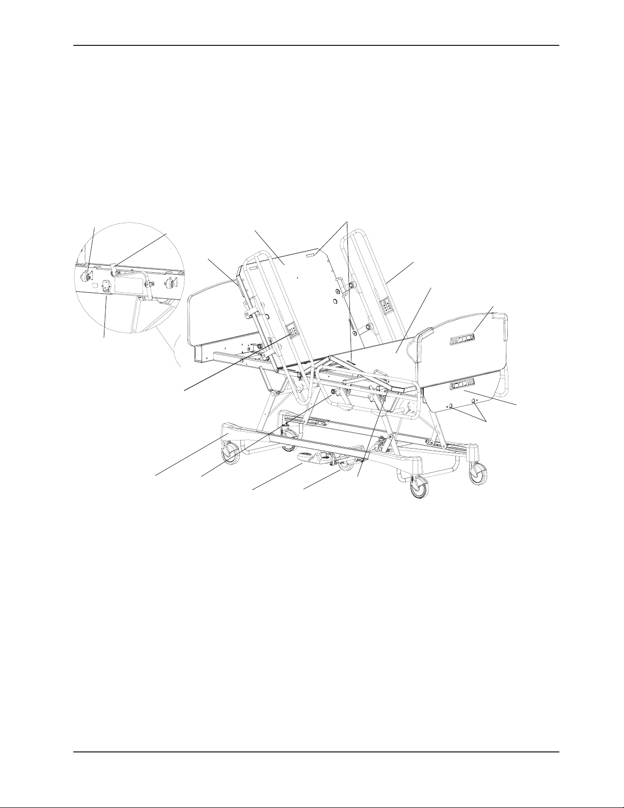
Introduction
RESTRAINT STRAP
LOCATIONS
HALF
-
LENGTH
SIDERAIL
FOOT SECTION
FOOTBOARD CONTROL
PANEL
(
OPTIONAL
)
EMERGENCY CRANK
OPENINGS
FOOT END
CONTROL PANEL
DRAINAGE BAG
HOOK
BRAKE
/
STEER
PEDAL
5
TH WHEEL
(
OPTIONAL
)
WHEEL COVER
(
OPTIONAL
)
SIDERAIL RELEASE
LEVER
MAIN SW ITCH
(
POWER
CONNECTOR
)
STORED
EMERGENCY
CRANK
(
OPTIONAL
)
BUMPER
HEAD SECTION
CPR RELEASE
HANDLE
OPTIONAL
FIXED SIDERAIL
CONTROL PANEL
(
OPTIONAL
)
INTENDED USE
This manual is designed to assist you with the maintenance of Stryker Model FL23SE Electrical MedSurg Bed. Carefully
read this manual thoroughly before using the equipment or beginning maintenance on it. To ensure safe operation of this
equipment, it is recommended that methods and procedures be established for educating and training staff on the safe
operation of this bed.
PRODUCT ILLUSTRATION
Return To Table of Contents
www.stryker.com 72-1048E MM FL2 3SE REV A 7
Page 8

SPECIFICATIONS
Safe Working Load
Introduction
Note: Safe Working Load indicates the sum
of the patient, mattress, and accessory
weight.
Overall
Length/Width
Weight with Head/Foot Boards 390 lbs 177 kg
Patient Sleep Surface 35” x 78” 88,9 x 198,1 cm
Recommended
Mattress Size
Maximum
Thickness
Minimum/
Maximum
Bed Height
Fowler Angle 0° to 62°
Knee Gatch
Angle
Trendelenburg/Reverse Trendelenburg +17° to -17°
Environmental
Conditions
Electrical
Requirement
Half-Length Siderails Raised
Full-Length Siderails Raised
Length/Width 35” x 78” or 80” 88,9 x 198,1 cm
BNQ
Standard
Non-BNQ Standard 5” 12,7 cm
With diameter 12,7 cm (5”) casters
With diameter 15,2 cm (6”) casters
With Auto Contour 0° to 25°
Without Auto Contour 0° to 32°
Transport and Storage
Operating
Complies with the following standards:
CSA C22.2 No. 601.1, UL 60601-1,
IEC 60601-1, 60601-2-38 and BNQ
6641-120 : 2003.
Bed with diameter
12.7 cm (5”) casters
Bed with diameter
15.2 cm (6”) casters
Ambient Temperature•
Relative Humidity•
Atmospheric Pressure•
Ambient Temperature•
Relative Humidity•
Atmospheric Pressure•
90,4” x 41,3”
90,4” x 39,9”
6” 15,2 cm
5” 12,7 cm
11,75” to 29” 29,8 to 737 cm
12,75” to 30” 32,4 to 76,2 cm
-40° to 158°F
10 to 100%
500 to 1060 hPa
50° to 104°F
5 to 95% without condensation
700 to 1060 hPa
100V~, 50-60Hz, 7.5A - Two 250V, 10A Fast Acting Fuses
120V~, 50-60Hz, 4A (9.8A with 120V Optional Auxiliary
200V~, 50-60Hz, 3.2A - Two 250V, 6.3A Slow Blow Fuses
220V~, 50-60Hz, 2.9A - Two 250V, 6.3A Slow Blow Fuses
240V~, 50-60Hz, 2.7A - Two 250V, 6.3A Slow Blow Fuses
500 lbs 227 kg
229,6 x 104,9 cm
229,6 x 101,3 cm
or 203,2 cm
-40° to 70°C
10° to 40°C
Outlet) - Two 250V, 10A Fast Acting Fuses
Stryker reserves the right to change specifications without notice.
Specifications listed are approximate and may vary slightly from unit to unit or by power supply fluctuations.
*This device has a 10% duty cycle.
Note
The Safe Working Load for the BNQ beds is of 390 lbs (177 kg).
Return To Table of Contents
8 72-1048E MM FL23SE REV A w ww.stryker.com
Page 9

Introduction
WARNING / CAUTION / NOTE DEFINITION
The words WARNING, CAUTION, and NOTE carry special meanings and should be carefully reviewed.
WARNING
Alerts the reader about a situation, which if not avoided, could result in death or serious injury. It may also describe
potential serious adverse reactions and safety hazards.
CAUTION
Alerts the reader of a potentially hazardous situation, which if not avoided, may result in minor or moderate injury to the
user or patient or damage to the equipment or other property. This includes special care necessary for the safe and
effective use of the device and the care necessary to avoid damage to a device that may occur as a result of use or
misuse.
Note
This provides special information to make maintenance easier or important instructions clearer.
Return To Table of Contents
www.stryker.com 72-1048E MM FL2 3SE REV A 9
Page 10
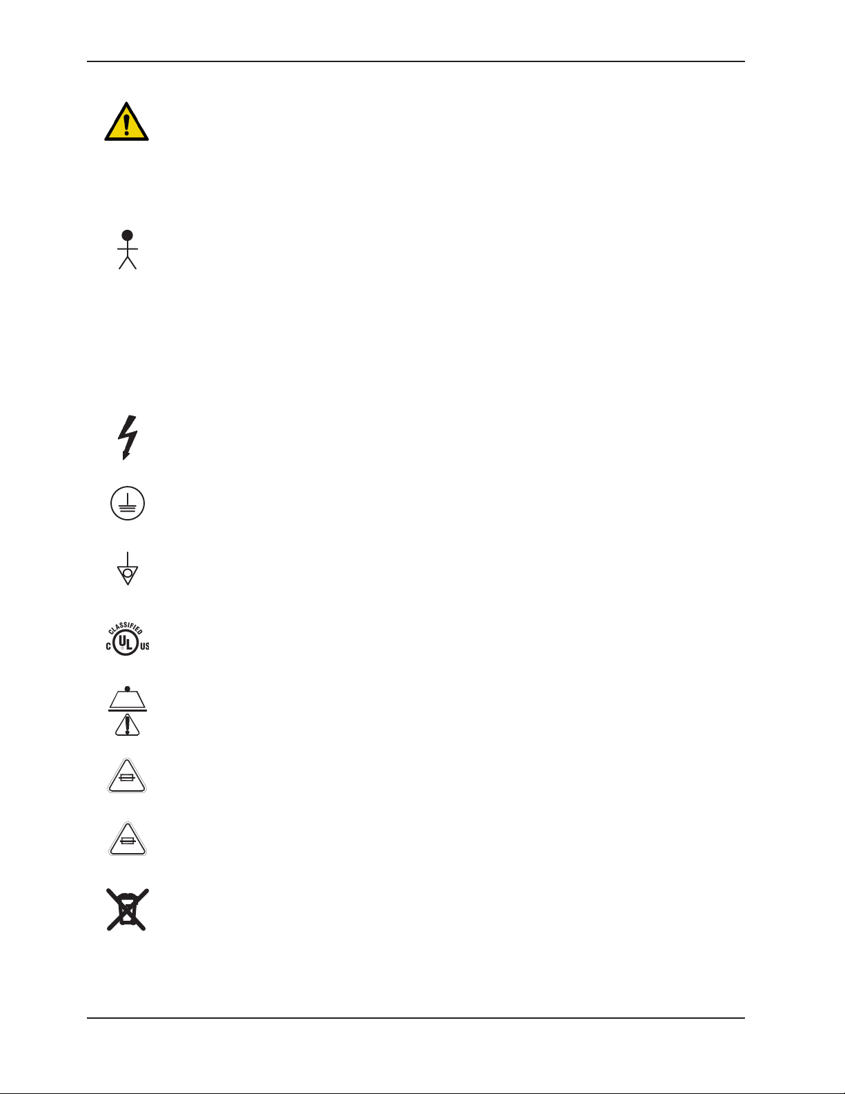
Symbols
~
10A 250V
6.3A 250V
Warning, Refer to Accompanying Documentation
Alternating Current
Type B Equipment: Equipment providing a particular degree of protection against electric shock,
particularly regarding allowable leakage current and reliability of the protective earth connection.
Class 1 Equipment: Equipment in which protection against electric shock does not rely on basic insulation
only, but which includes an additional safety precaution in that means are provided for the connection of
the equipment to the protective earth conductor in the fixed wiring of the installation in such a way that
accessible metal parts cannot become live in the event of a failure of the basic insulation.
IPX4
Protection from liquid splash
Dangerous Voltage Symbol
Protective Earth Terminal
Potential Equalization Symbol
Medical Equipment Classified by Underwriters Laboratories Inc. with respect to Electric Shock, Fire,
Mechanical and Other Specified Hazards Only in Accordance with UL 60601-1, First Edition (2003) and
CAN/CSA C22.2 No. 601.1-M90 with updates 1 and 2.
Safe Working Load Symbol
Fuse rating for bed with 100V~ and 120V~ electric systems.
Fuse rating for bed with 200V~, 220V~ and 240V~ electric systems.
In accordance with European Directive 2002/96/EC on Waste Electrical and Electronic Equipment
(WEEE), this symbol indicates that the product must not be disposed of as unsorted municipal waste,
but should be collected separately. Refer to your local distributor for return and/or collection systems
available in your country.
Return To Table of Contents
10 72-1048E MM FL2 3SE REV A www.stryker.com
Page 11
www.stryker.com 72-1048E MM FL2 3SE REV A 11
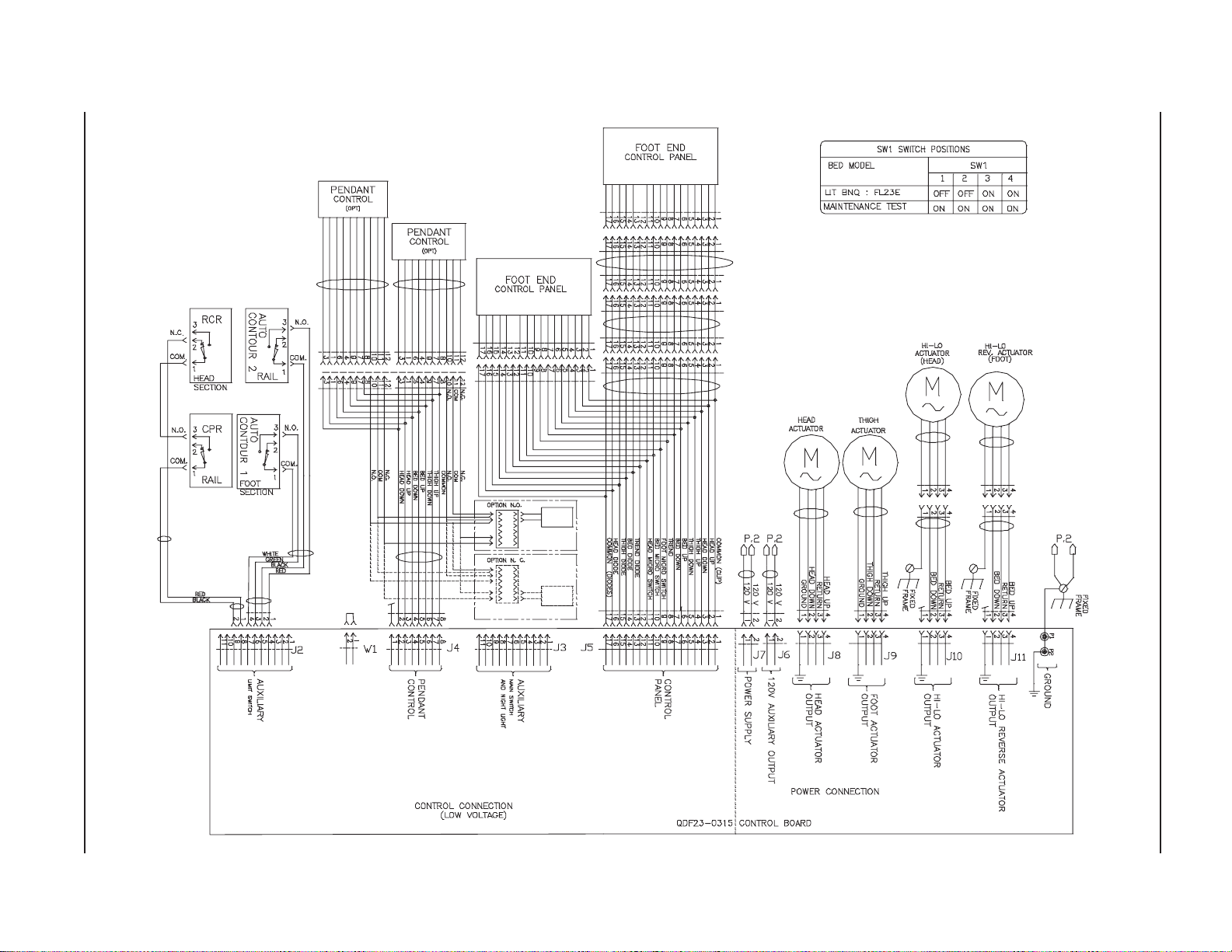
CONNECTION DIAGRAM
Electrical Service Information
Return To Table of Contents
Page 12
12 72-1048 E MM FL 23SE REV A www.stryker.com
Return To Table of Contents
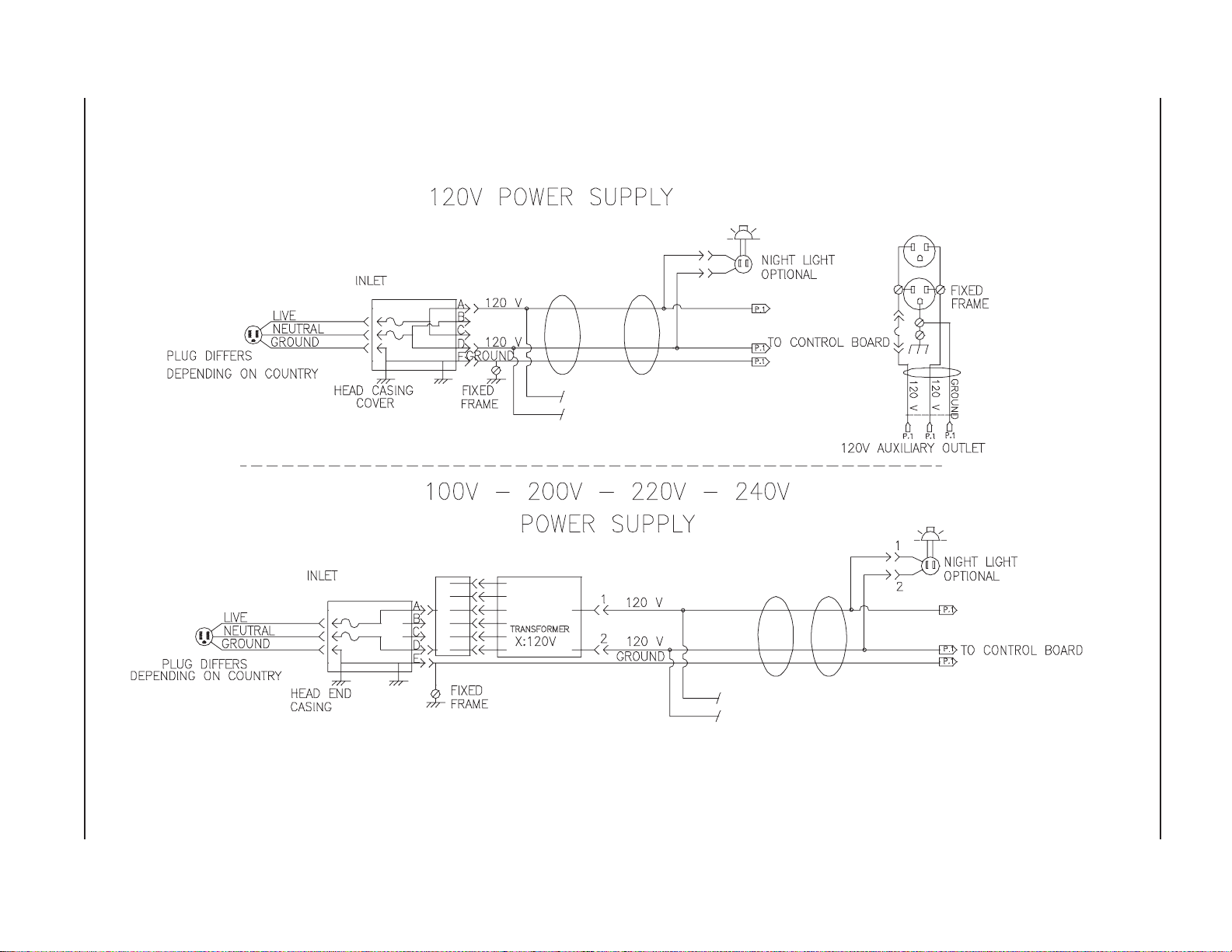
CONNECTION DIAGRAM (CONTINUED)
Electrical Service Information
Page 13

Preventative Maintenance
WARNING
Use only replacement parts provided by Stryker.
ANNUAL CHECKLIST
______
______
______
______
______
______
______
______
______
______
______
______
______
______
______
______
______
______
______
All fasteners secure.
Inspect for excessive wear the oil-impregnated bronze shoulder spacers found at the bed hinge points.
Replace as needed. Do not lubricate these spacers.
On both sides of the bed, depress fully down the side of the pedal identified with a red sticker and ensure
that the brakes are applied and the bed immobilized. Toggle the pedal to neutral and ensure the brakes
are released.
On both sides of the bed, depress fully down the side of the pedal identified with a green sticker and ensure
that the steer mode (fifth wheel (optional) or bed wheel) is engaged. Toggle the pedal to neutral and ensure
that the steer mode disengages.
Siderails move smoothly and latch properly in high position.
Ensure that each control of the inner and outer head siderail control panels (optional) and those of the
removable pendant control (optional) are working properly.
All controls of the foot end panel and those of the foot board panel (optional) working properly, including
Trendelenburg and lockout LED’s.
Fowler and Knee Gatch (if raised) flatten and the Fowler control motor resets itself automatically when the
two CPR handles (optional) are pulled until Fowler is flattened. Wait about 30 seconds, the time for the
Fowler motor to reset itself, and then raise the Fowler to ensure that the resetting of the motor has indeed
occurred.
Verify the Fowler, Knee Gatch and Hi-Lo movements to ensure that the motion interrupt switch integrated
to the four electric actuators is operating properly.
Auxiliary outlet (option available only with 120V beds) working properly.
Night light (optional) working properly.
Head end bumpers tightly secured to frame and working properly.
No rips or cracks in mattress cover.
Power cord is not frayed. Replace if the protective sleeve is cut or torn.
No cables worn or pinched.
All electrical connections tight.
All grounds secured to the frame.
All casters roll properly. Check caster for cuts, wear, etc.
Measure current leakage and grounding continuity of the bed and the optional auxiliary outlet. Check with
our Technical Service department for the acceptable values.
Bed Serial Number:
Completed by: _______________________________________ Date: _________________
Return To Table of Contents
www.stryker.com 72-1048E MM FL2 3SE REV A 13
Page 14

Cleaning
BED CLEANING
CAUTION
Do not use harsh cleaners, solvents or detergents. Equipment damage could occur. • Do not steam clean, hose off
or ultrasonically clean the bed. Do not immerse any part of the bed. The bed electrical parts may be damaged
by exposure to water.
Germicidal disinfectant, used as directed, and/or Chlorine Bleach products are not considered as mild detergents. •
These products are corrosive in nature and may cause damage to your bed if used improperly. If these types of
products are used, ensure the beds are wiped with clean water and thoroughly dried following cleaning. Failure to
properly rinse and dry the beds will leave a corrosive residue on the surface of the bed, possibly causing premature
corrosion of critical components. Failure to follow the above directions when using these types of cleaners may void
the product’s warranty.
Procedure:
Hand wash all surfaces of the bed with a soft cloth moistened with a solution of lukewarm water and a mild detergent.
Wipe the bed clean and dry thoroughly to avoid build up of cleaning solution.
MATTRESS CARE
WARNING
Inspect the mattress after each use. Discontinue use if any cracks or rips, which may allow fluid to enter the mattress,
are found in the mattress cover. Failure to properly clean the mattress, or dispose of it if defective, may increase the risk
of exposure to pathogenic substances and may bring about diseases to the patient and user.
Inspection
Implement local policies to address regular care, maintenance, and cleaning of mattresses and covers. The cover •
cleaning procedure can be found below and on the bed label.
Inspect mattress cover surface, interior and exterior, as well as zip fasteners and cover inner surface if mattresses •
have zip fasteners, regularly for signs of damage. If the mattress cover is heavily stained or soiled, or is torn, remove
the mattress from service.
Cleaning
Stains: Wash with lukewarm water using a mild detergent. Rinse with water and let dry. For tough stains, use bleach
diluted with ten parts of water.
Return To Table of Contents
14 72-1048E MM FL23 SE REV A www.stryker.com
Page 15

Troubleshooting Guide
Problem/Failure Recommended Action
No power to bed Is the bed power switch at the head end of the bed •
turned on?
Is the power cord connected to the power connector •
and plugged into the wall outlet?
Is the power cord severed? Replace if so. •
Are the two fuses inside the power connector still •
operational (see pg. 51)?
Verify power at the wall outlet.•
No bed up or down motion when:
The removable pendant control (optional) is used. •
The foot board command is used.•
No Fowler up or down motion when:
The siderail (optional) or removable pendant control •
(optional) is used.
The foot board command is used.•
The Fowler does not fully raise. This situation arises when the CPR emergency release
No Knee Gatch up or down motion when:
The siderail (optional) or removable pendant control •
(optional) is used.
The foot board command is used.•
Is the Hi-Lo lockout activated (LED off)? If so, deactivate •
it (LED on).
Is the cable of the removable pendant control (optional) •
properly connected to the bed connector under the
mattress support?
Check points of the “No power to bed” problem •
described above.
Is the Fowler lockout activated (LED off)? If so, deactivate •
it (LED on).
Is the cable of the siderail control panel (optional) or •
of the removable pendant control (optional) properly
connected to the bed connector under the mattress
support?
Check points of the “No power to bed” problem •
described above.
(optional) is used to partially lower the Fowler. The use
of the CPR for this purpose creates a situation where the
Fowler motor is out of sync with the actual position of the
Fowler. To correct the situation:
Lower the Fowler • completely using a CPR handle or
the Fowler electric control to enable the Fowler motor
to reset itself and thus synchronize its course with the
actual position (flatten) of the Fowler.
Is the Knee Gatch lockout activated (LED off)? If so, •
deactivate it (LED on).
Is the cable of the siderail control panel (optional) or •
of the removable pendant control (optional) properly
connected to the bed connector under the mattress
support?
Check points of the “No power to bed” problem •
described above.
Return To Table of Contents
www.stryker.com 72-1048E MM FL2 3SE REV A 15
Page 16

Troubleshooting Guide
Problem/Failure Recommended Action
The positioning mechanisms of the Fowler, and/or
the Knee Gatch, and/or the bed height operate with
difficulty.
No Auto Contour (optional) motion. Is the Knee Gatch lockout activated (LED off)? If so, •
Improper operation of the CPR emergency release
(optional): Knee Gatch does not lower and/or the Fowler
actuator does not reset.
Check the four actuator screws to verify their lubrication •
condition and apply grease if needed (see pg. 20).
deactivate it (LED on).
Check and replace if needed the two Auto Contour limit •
switches (see pg. 52).
Check and replace if needed the two CPR mechanism •
limit switches (see pg. 54).
Return To Table of Contents
16 72-1048E MM FL23SE REV A www.stryker.com
Page 17

Quick Reference Replacement Parts List
Note
The parts and accessories listed on this page are all currently available for purchase. Some of the parts identified on
the assembly drawing parts in this manual may not be individually available for purchase. Please call Stryker Customer
Service USA: 1-800-327-0770 (Option 2) or Canada: 1-888-233-6888 for availability and pricing.
Part Name Part Number
Electric/Electronic Components
Motor Control Board QDF23-0315
Micro Switch 1325P003 / QDF9159
Fuse - Fast Acting 10A, 250V (100/120V) QDF8078
Fuse - Slow Blow 6.3A, 250V (200/220/240V) QDF8068
Power Cord with Straight North American Molded Plug QDF8066
Night Light (Optional) QDF9539
5A Circuit Breaker for Auxiliary Outlet (optional) QDF9025
Hi-Lo Actuator 23-0702
Head Section Actuator 23-0335
Thigh Section Actuator 23-0336
Toroidal Transformer - International Series Beds QDF14-1160
Stand-Off Pins: Motors Control Board QP23-0735
Strain-Relief Bushing QDF9541
Support for the Foot End Control Panel Membrane QP17-0127-07
Foot End Control Panel Membrane QDF17-0693 / QDF17-0180
Siderail Components
Protective Cap QDFP1514
Transfer Plate - Half-Length Siderail 23-0777G / 23-0778G
23-0817G / 23-0818G
Left Inner Membrane without Nurse Call
Right Inner Membrane without Nurse Call
Right Inner Membrane with Nurse Call
Left Inner Membrane with Nurse Call
Left Outer Membrane QDF23-0405
Right Outer Membrane QDF23-0406
PVC Protector for Painted Head Half-Length Siderails 23-0476
QDF23-0392 / QDF23-0393
QDF23-0396 / QDF23-0397
PVC Protector for Painted Foot Half-Length Siderails 23-0478
PVC Protector for Painted Full-Length Siderails 23-0641
Return To Table of Contents
www.stryker.com 72-1048E MM FL2 3SE REV A 17
Page 18

Quick Reference Replacement Parts List
Part Name Part Number
Mattress Support Components
Lateral Mattress Retainer QP14034-07
I.V. Pole Holder QP17-0121
Caster
6” with Lock Mechanism RD25038807
6” without Lock Mechanism RD25049307
6” with Steer Mechanism RD25049607
5” with Lock Mechanism RD25049407
5” without Lock Mechanism RD25039107
5” with Steer Mechanism RD25049507
Fifth Wheel Mechanism 5” Caster (Optional) RL5
Base Components
Rue Ring Cotter Diameter 3/8” QDF7878
Green Sticker - Fifth Wheel QE71-0496
Red Sticker - Brake QE71-0511
Wheel Cover - Right (Optional) QP28-0299-07
Wheel Cover - Left (Optional) QP28-0300-07
Brake/Steer Pedal QP23-0627
Velcro Fastener 25-0550
Miscellaneous
Grey Spray Paint DDCAP-GSP
Shoulder Spacer QDF17-0020
Nylon Cable Tie QDF9518
Return To Table of Contents
18 72-1048E MM FL23SE REV A www.stryker.com
Page 19
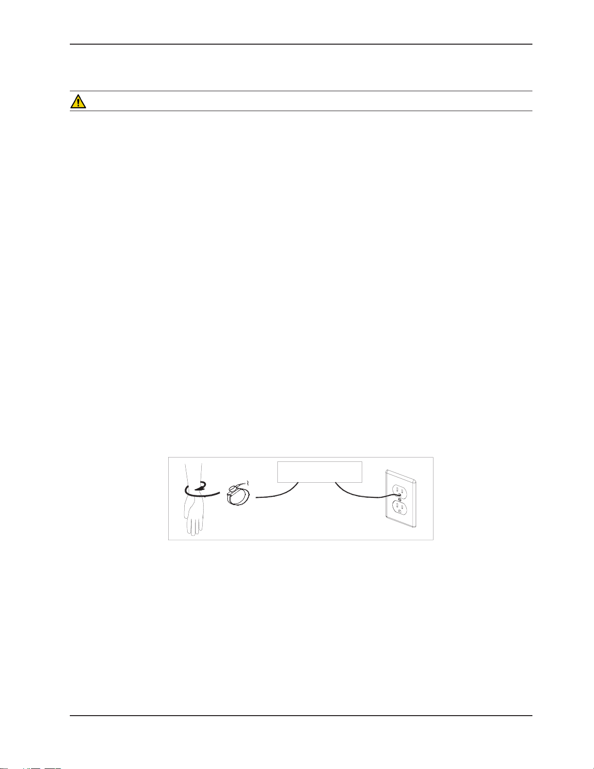
GROUNDING DIAGRAM
BED
Operation Guide
MAINTENANCE PROCEDURES
WARNING
Always unplug the bed power cord when cleaning or servicing the bed.•
To prevent injury when working under the bed with the bed in the high position, always place blocks under the Hi-Lo •
levers and apply the brakes. Always unplug the bed power cord from the wall outlet when servicing or cleaning the
bed.
STATIC DISCHARGE PRECAUTIONS
The electronic circuits of the bed are protected from static electricity damage only while the bed is assembled. It is
extremely important that all service personnel always use adequate static protection when servicing the electronic
components of the bed.
STATIC PROTECTION EQUIPMENT
The necessary equipment for a proper static protection is:
1 static wrist strap •
1 grounding plug •
1 test lead with a banana plug on one end and an alligator clip on the other.•
STATIC PROTECTION PROCEDURE
Unplug the bed power cord from the wall outlet. 1.
Insert the grounding plug into a properly grounded hospital grade wall receptacle. Plug the banana plug of the test 2.
lead into the receptacle on the grounding plug. Connect the alligator clip on the other end of the test lead to a
ground point on the bed.
Place the static control wrist strap on your wrist. Connect the clip at the other end of the wrist strap cord to a ground 3.
point on the bed.
Return To Table of Contents
www.stryker.com 72-1048E MM FL2 3SE REV A 19
Page 20
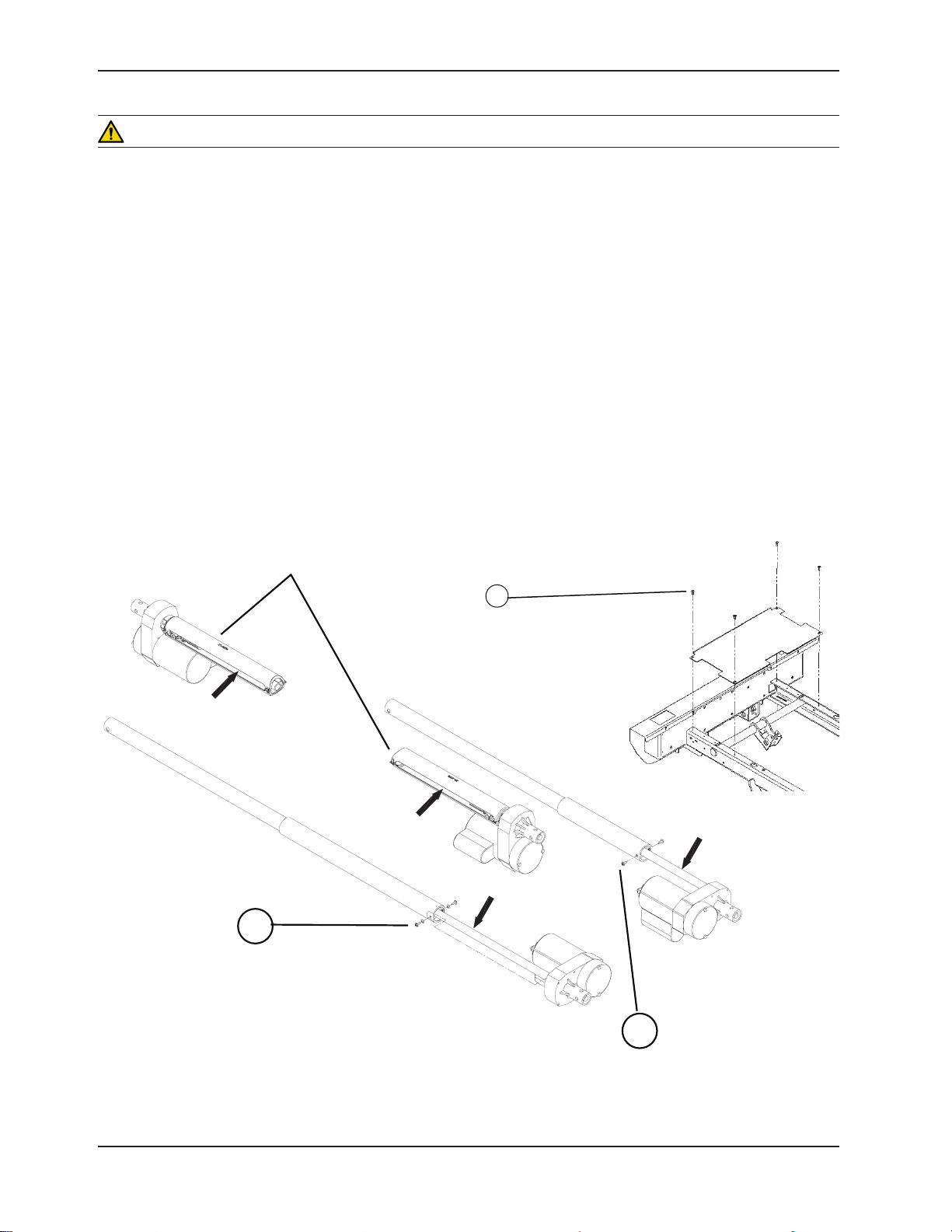
Service Information
C
B
Screw Covers Shown Are Optional
A
WARNING
Always unplug the bed power cord when cleaning or servicing the bed.•
To prevent injury when working under the bed with the bed in the high position, always place blocks under the Hi-Lo •
levers and apply the brakes. Always unplug the bed power cord from the wall outlet when servicing or cleaning the
bed.
ACTUATOR LUBRICATION
Note
In compliance with the service life requirement of the BNQ 6641-120/2003 standard, this unit was designed maintenance
free with regard to lubrication. However, if the bed is used improperly or cleaned without following the recommendations
set forth in the Maintenance Manual (presence of cleaning detergent on the actuator screws), a lubrication of the
actuator could be necessary.
Tools Required:
No. 2 Phillips Screwdriver •
1/4” Ratchet (with 6” extension) and 5/16” Socket •
Bungee Cords •
OG2 Grease•
Brush •
Screw Covers
Shown are Optional
Figure 2.2
Return To Table of Contents
20 72-1048E MM FL2 3SE REV A www.stryker.com
Page 21

Service Information
ACTUATOR LUBRICATION (CONTINUED)
Procedure:
Head and Thigh Actuators
Completely raise the bed and apply the brakes. 1.
Completely raise the head section and flatten the thigh section to expose maximum screw threads on both actuators. 2.
Lower the four siderails.
Unplug the power cord from the wall outlet. 3.
Lift and fold back the foot section toward the head end of the bed. Attach it to the bed using bungee cords. 4.
Using a no. 2 Phillips screwdriver, remove the four screws (A) holding the cover plate to the frame and remove the 5.
plate. Remove the optional night light if present.
a. Using a 1/4” ratchet (with 6” extension) and a 5/16” socket, remove the two screws (B) holding the dust tube 6.
of each knee gatch actuator. Push the tube to free it.
b. For the head actuator, remove the two screws, spring washer (C) holding the dust tube of the actuator. Push
the tube to free the threads.
Using a brush, apply grease on the screw threads. Make sure the grease reaches the bottom of the threads.7.
Replace the dust tubes. 8.
Using the electric controls, raise and lower several times the Fowler and Knee Gatch to spread the grease evenly. 9.
Replace the cover plate.10.
Hi-Lo Actuators
Lower the bed completely. 1.
Completely raise the head and foot sections, then lift and fold back the foot section toward the head end of the 2.
bed.
Unplug the power cord from the wall outlet. 3.
Using a brush, apply grease on the threads of the bed lift actuators screws. Optional dust tubes may be present, if 4.
so, simply apply grease through the dust tube side openings.
Using the electric controls, raise and lower the bed several times to spread the grease evenly.5.
Return To Table of Contents
www.stryker.com 72-1048E MM FL2 3SE REV A 21
Page 22

I
I
J
A
SIDERAIL REPLACEMENT
E
H
G
K
E
F
A
D
C
J
I
HALF-LENGTH RAIL REPLACEMENT
Tools Required:
3/8” Drive Ratchet•
Small Slotted Head Screwdriver •
Long Nose Pliers •
Retaining Ring Pliers •
Rubber Mallet•
7/16” Socket•
Service Information
Right Head Siderail Shown
Return To Table of Contents
22 72-1048E MM FL2 3SE REV A www.stryker.com
Figure 4.1 A
Page 23

Service Information
SIDERAIL REPLACEMENT (CONTINUED)
HALF-LENGTH SIDERAIL
Procedure:
Completely raise the bed and apply the brakes. 1.
Position all the mattress support sections to flat. 2.
Unplug the bed power cord from the wall outlet. 3.
Raise the siderail needing repair. 4.
Using a small slotted head screwdriver and long nose pliers, remove the two protective caps (A). Be careful while 5.
using the tools not to damage the siderail paint.
Note
Replace the caps using a rubber mallet. The removal of the caps may damage them; make sure you have some on
hand.
a. For a head siderail, using the retaining ring pliers, remove the retaining ring on one arm and using the 7/16” 6.
socket, remove the nut, spring washer and spacer holding the rail in place.
b. For a foot siderail, remove using the 7/16” socket the nut, the spring washer and the spacer holding
the siderail in place (B).
Note
Inspect the self-lubricating bearings for wear and replace them if need be.
Reverse the above steps to install the replacement rail. 7.
Verify the siderail movement for proper operation before returning the bed to service.8.
Return To Table of Contents
www.stryker.com 72-1048E MM FL2 3SE REV A 23
Page 24

Service Information
HALF-LENGTH SIDERAIL ASSEMBLY REPLACEMENT
Tools Required:
3/8” Drive Ratchet•
7/16” Socket •
7/16” Combination Wrench•
Diagonal Pliers •
Procedure:
Note
Unless otherwise indicated, refer to Figure 4.1 A on pg. 22 for the following replacement procedure.
Completely raise the bed and apply the brakes. 1.
Depending on the position of the siderail needing repair, place the mattress support sections as follows: 2.
Head Siderail: Completely raise the head section. •
Foot Siderail: Lower completely the head section. Completely raise the thigh section, then lift and fold back the •
foot section toward the head end of the bed.
Unplug the bed power cord from the wall outlet. 3.
Raise the siderail needing repair. 4.
Using diagonal pliers, cut, if applicable, the cable ties holding the siderails fixed control cable (optional). Loosen the 5.
lock ring (D) and unplug the cable.
Note
Note the position and the gathering of the cable before cutting the cable ties to make sure the replacement cable will
be connected correctly.
Using the 7/16” socket and 7/16” combination wrench, remove the two locknuts and bolts (E) holding the two half 6.
bushings (F), the stopper (G) and the siderail mechanism to each of the two siderail support (H). Remove the
half bushings and the mechanism from their location, hold the bushings tightly to prevent them from falling to the
ground.
Note
First, remove the two locknuts and bolts at one end of the assembly and, while holding the assembly, finish with the ones
at the opposite end.
Reverse the above steps to install the replacement siderail assembly. 7.
Verify the siderail for proper operation before returning the bed to service.8.
Return To Table of Contents
24 72-1048E M M FL23SE REV A www.stryker.com
Page 25

Service Information
TRANSFER PLATE REPLACEMENT
Tools Required:
3/8” Drive Ratchet•
7/16” Socket •
7/16” Combination Wrench •
Torque Wrench •
Procedure:
Note
Unless otherwise indicated, refer to Figure 4.1 A on pg. 22 for the following replacement procedure.
Completely raise the bed and apply the brakes. 1.
Depending on the siderail position, place the mattress support sections as follows: 2.
Head Siderail: Completely raise the head section. •
Foot Siderail: Lower completely the head section. Completely raise the thigh section, then lift and fold back the •
foot section toward the head end of the bed.
Unplug the bed power cord from the wall outlet. 3.
Lower the siderail needing repair. 4.
Using the 7/16” socket and 7/16” combination wrench, remove the two locknuts, bushings, washers and bolts (I) 5.
holding the transfer plate (J) to the siderail mechanism.
Note
At assembly, tighten the two locknuts to a 75 in/lb torque using the torque wrench.
Reverse the above steps to install the replacement transfer plate. 6.
Verify the siderail for proper operation before returning the bed to service.7.
Return To Table of Contents
www.stryker.com 72-1048E MM FL2 3SE REV A 25
Page 26
26 72-1048E MM FL23SE REV A www.stryker.com
A
D
F
J
C
F
C
E
F
A
B
D
F
G
H
I
Return To Table of Contents
Service Information
Figure 4.1 B
Page 27

Service Information
FULL-LENGTH SIDERAIL PIVOT TUBE REPLACEMENT
Tools Required:
1/2” Combination Wrench •
Rubber Mallet •
Procedure:
Note
Unless otherwise indicated, refer to Figure 4.1 B on pg. 26 for the following replacement procedure.
Completely raise the bed and apply the brakes. 1.
Unplug the bed power cord from the wall outlet. 2.
Lower the siderail needing repair. 3.
Using the 1/2” combination wrench, remove the two bolts and washers (A) holding the pivot tube ends to the siderail 4.
mechanism arms. Use a rubber mallet to free the tube ends from the arms.
Slide the tube out of its location.5.
Note
Apply grease on a 4” distance from both ends of the tube.
Reverse the above steps to install the replacement pivot tube. 6.
Verify the siderail movement before returning the bed to service.7.
Return To Table of Contents
www.stryker.com 72-1048E MM FL2 3SE REV A 27
Page 28

Service Information
FULL-LENGTH RAIL REPLACEMENT
Tools Required:
1/2” Combination Wrench •
Rubber Mallet •
Procedure:
Note
Unless otherwise indicated, refer to Figure 4.1 B on pg. 26 for the following replacement procedure.
Completely raise the bed and apply the brakes. 1.
Unplug the bed power cord from the wall outlet. 2.
Raise the siderail needing repair. 3.
Loosen, if applicable, the lock ring (B) and unplug the removable pendant control (optional) cable. Remove the 4.
pendant control from the siderail by sliding it out its supports.
Using the 1/2” combination wrench, remove the four bolts and washers (A, C) holding the rail to the siderail 5.
mechanism arms. Use a rubber mallet to free the tube ends from the arms.
Note
Hold the rail firmly when removing the last bolts.
Reverse the above steps to install the replacement rail. 6.
Verify the siderail movement before returning the bed to service.7.
Return To Table of Contents
28 72-1048E MM FL23SE REV A www.stryker.com
Page 29

Service Information
FULL-LENGTH SIDERAIL ASSEMBLY REPLACEMENT
Tools Required:
No. 2 Phillips Screwdriver•
Two 1/2” Combination Wrenches•
Procedure:
Note
Unless otherwise indicated, refer to Figure 4.1 B on pg. 26 for the following replacement procedure.
Completely raise the bed and raise the siderail needing repair. 1.
Unplug the bed power cord from the wall outlet.2.
Remove the head and foot boards. 3.
Using two 1/2” combination wrenches, remove the two locknuts and bolts (K, Figure 4.3 C, 4. pg. 43) holding the two
bumpers to their supports at the head end of the bed.
Using the no. 2 Phillips screwdriver, remove the seven screws (Q, Figure 4.3 C, 5. pg. 43) holding the cover to the head
end casing. Remove the cables connected to the power connector after having noted their location and remove the
cover.
Using the no. 2 Phillips screwdriver, remove the 10 screws (A, Figure 4.2 A, 6. pg. 32) holding the cover and the I.V.
pole holders to the foot casing. Lift and remove the cover while taking care to disconnect the control panel cable
(B, Figure 4.2 A, pg. 32) from the control board and, if applicable, the foot end casing connector cable (C, Figure
4.2 A, pg. 32) (optional).
Using the no. 2 Phillips screwdriver, remove the four screws (D) holding together the two parts of both siderail 7.
mechanism covers. Remove the covers.
Using the 1/2” combination wrench, remove the four nuts, washers and bolts (E) holding the siderail release handle 8.
to the seat section.
Using the 1/2” combination wrench, remove the two nuts, washers and bolts (F) holding each end of the full-length 9.
siderail to the head end and foot end casings.
Reverse the above steps to install the replacement siderail assembly. 10.
Verify the siderail for proper operation before returning the bed to service.11.
Return To Table of Contents
www.stryker.com 72-1048E MM FL2 3SE REV A 29
Page 30

Service Information
FULL-LENGTH SIDERAIL RELEASE HANDLE REPLACEMENT
Tools Required:
Needle Nose Pliers •
No. 1 Phillips Screwdriver •
Bungee Cord •
7/16” Combination Wrench •
Procedure:
Note
Unless otherwise indicated, refer to Figure 4.1 B on pg. 26 for the following replacement procedure.
Completely raise the bed and apply the brakes. 1.
Unplug the bed power cord from the wall outlet. 2.
Raise both siderails. 3.
Using needle nose pliers, remove the return spring (G). 4.
Attach the siderail needing repair to the other siderail using a bungee cord. 5.
Using the No. 1 Phillips screwdriver, remove the six screws (H) holding both parts of the release handle. Hold the 6.
lower part to prevent it from falling.
Using the 7/16” combination wrench, remove the upper part of the handle by turning the lock rod (I) towards the 7.
floor.
Note
Use the same procedure to insert the upper part of the new handle on the rod, but this time turn the lock rod up.
Reverse the above steps to install the replacement release handle. 8.
Verify the release handle for proper operation before returning the bed to service.9.
Return To Table of Contents
30 72-1048E MM FL23SE RE V A www.stryker.com
Page 31

Service Information
FULL-LENGTH SIDERAIL LOCKING HOOK REPLACEMENT
Tools Required:
No. 2 Phillips Screwdriver•
Bungee Cord•
Two 1/2” Combination Wrenches•
Procedure:
Note
Unless otherwise indicated, refer to Figure 4.1 B on pg. 26 for the following replacement procedure.
Completely raise the bed and raise the siderail needing repair.1.
Unplug the bed power cord from the wall outlet. 2.
If the hook is at the head end of the bed, follow steps 3 to 6, then go to step 8.
If the hook is at the foot end of the bed, go directly to step 7.
Head End
Remove the head board.3.
Raise the defective siderail.4.
Using the two 1/2” combination wrenches, remove the two locknuts and bolts (K, Figure 4.3 C, 5. pg. 43) holding the
bumpers to their support.
Using the No. 2 Phillips screwdriver, remove the seven screws (Q, Figure 4.3 C, 6. pg. 43) holding the cover of the head
box. Remove cables connected to power connector taking note of their position then remove cover.
Foot End
Using the No. 2 Phillips screwdriver, remove the 10 screws (A, Figure 4.2 A, 7. pg. 32) holding the cover as well as
the two I.V. poles to the foot box. Raise and remove the cover taking care to disconnect the electronic board first,
the cable (B, Figure 4.2 A, pg. 32) of the control panel and, if applicable, the cable (C, Figure 4.2 A, pg. 32) of the
connector from the foot box (optional).
Using the No. 2 Phillips screwdriver, remove the four screws (D) holding the two parts of the plastic cover over the 8.
siderail mechanism. Remove cover.
Using the two 1/2” combination wrenches, remove locknut, shoulder spacer and bolt (J) holding the locking hook 9.
to the plate. Remove hook.
Reverse the preceding steps to install the new hook.10.
Verify siderail for proper operation before returning the bed to service.11.
Return To Table of Contents
www.stryker.com 72-1048E MM FL2 3SE REV A 31
Page 32

A
A
A
B
C
D
E
F
Service Information
FOOT END CONTROL PANEL REPLACEMENT
Tools Required:
No. 2 Phillips Screwdriver •
Note
The control panel is made of a membrane and its support. Both parts should be ordered for this replacement procedure.
Refer to the “Quick Reference Replacement Parts List” section on pg. 17.
Procedure:
Figure 4.2 A
Completely raise the bed and apply the brakes. 1.
Unplug the bed power cord from the wall outlet. 2.
Remove the foot board. 3.
Using the No. 2 Phillips screwdriver, remove the 10 screws (A) holding the cover and the I.V. pole holders to the foot 4.
casing.
Use the Static Discharge Precautions procedure (see 5. pg. 19).
Lift and remove the cover taking care to disconnect the electronic board, the cable (B) from the control panel and, 6.
if applicable, the foot casing connector cable ((optional), C). Lay the cover on a workbench.
Using the No. 2 Phillips screwdriver, remove the three screws, washers and spacers (D) holding the panel to the 7.
cover.
Reverse the above steps to install the new control panel. 8.
Verify all the controls of the foot end control panel before returning the bed to service.9.
Return To Table of Contents
32 72-1048E MM FL23SE REV A www.stryker.com
Page 33

Service Information
FOOT END CASING CONNECTOR REPLACEMENT (OPTIONAL)
Tools Required:
No. 2 Phillips Screwdriver •
3/8” Combination Wrench•
Procedure:
Note
Unless otherwise indicated, refer to Figure 4.2 A on pg. 32 for the following replacement procedure.
Completely raise the bed and apply the brakes. 1.
Unplug the bed power cord from the wall outlet. 2.
Remove the foot board. 3.
Using the No. 2 Phillips screwdriver, remove the 10 screws (A) holding the cover and the two I.V. pole holders to the 4.
foot casing.
Lift and remove the cover taking care to disconnect the electronic board, the control panel cable (B) and the foot 5.
casing connector cable (C). Lay the cover on a workbench.
Using the 3/8” combination wrench, remove the two locknuts, shoulder spacers and screws (E) holding the connector 6.
and the seal (F) to the cover. Remove the defective connector using the 3/8” combination wrench and No. 2 Phillips
screwdriver. Keep the seal for the replacement connector.
Reverse the above steps to install the new connector. 7.
Verify all the controls of the foot end control panel for proper operation before returning the bed to service.8.
Return To Table of Contents
www.stryker.com 72-1048E MM FL2 3SE REV A 33
Page 34

A
B
C
D
A
Service Information
FOOT BOARD CONTROL PANEL REPLACEMENT (OPTIONAL)
Tools Required:
No. 2 Phillips Screwdriver •
Double-Sided Tape •
Procedure:
Note
The control panel is made of a membrane and its support. Both parts should be ordered for this replacement procedure.
Refer to the “Quick Reference Replacement Parts List” section on pg. 17.
Figure 4.2 B
Completely raise the bed and apply the brakes. 1.
Unplug the bed power cord from the wall outlet. 2.
Remove the foot board and lay it on a workbench. 3.
Using the No. 2 Phillips screwdriver, remove the seven screws (A) holding the support cover to the inner face of the 4.
foot board and remove the cover.
Disconnect the foot board panel cable (B). 5.
Using the No. 2 Phillips screwdriver, remove the last screw (C) holding the control panel to the foot board. Remove 6.
the panel. A small part of the panel cable is stuck to the inner face of the panel with a small double-sided tape. Do
the same at reassembly.
Reverse the above steps to install the replacement foot board panel. 7.
Verify all the controls of the foot board panel for proper operation before returning the bed to service. 8.
Return To Table of Contents
34 72-1048E MM FL23SE REV A www.stryker.com
Page 35

Service Information
FOOT BOARD CONNECTOR REPLACEMENT (OPTIONAL)
Tools Required:
No. 2 Phillips Screwdriver •
9 mm Combination Wrench •
Procedure:
Note
This connector is present when the bed is equipped with a foot board control panel.
Unless otherwise indicated, refer to Figure 4.2 B on pg. 34 for the following replacement procedure.
Completely raise the bed and apply the brakes. 1.
Unplug the bed power cord from the wall outlet. 2.
Remove the foot board and lay it on a workbench. 3.
Using the No. 2 Phillips screwdriver, remove the seven screws (A) holding the support cover to the inner face of the 4.
foot board and remove the cover.
Disconnect the foot board connector cable (B). 5.
Using the 9 mm combination wrench and No. 2 Phillips screwdriver, remove the two locknuts, washers, sleeves and 6.
screws (D) holding the connector to its support. Remove the defective connector.
Reverse the above steps to install the replacement connector. 7.
Verify the foot board controls for proper operation before returning the bed to service.8.
Return To Table of Contents
www.stryker.com 72-1048E MM FL2 3SE REV A 35
Page 36

A
C
B
B
A
Service Information
SIDERAIL CONTROL PANEL MEMBRANE REPLACEMENT
Tools Required:
No. 2 Phillips Screwdriver•
Note
The replacement of a membrane implies that the one facing it on the inner or outer control panel also has to be replaced.
Service kits, including both membranes are available.
Figure 4.2 C
Procedure:
Completely raise the bed and apply the brakes. Bring the head section to horizontal position. 1.
Unplug the bed power cord from the wall outlet. 2.
Raise the head siderail needing repair. 3.
Properly ground yourself (see 4. pg. 19).
Detach the two membranes (A) from their mounting plates and let them hang down. 5.
Using a No. 2 Phillips screwdriver, remove the eight screws (B) holding together the two sections of the control 6.
panel housing.
Open the housing, disconnect the defective membrane cable (C) and remove the membrane. 7.
Reverse the above steps to install the new control panel membranes.8.
Note
Make sure to connect the membrane cables before fastening together the two sections of the control panel housing.
Stick the membranes to the support at the end of the replacement procedure.
Verify all the siderail functions for proper operation before returning the bed to service.9.
Return To Table of Contents
36 72-1048E M M FL23SE REV A www.stryker.com
Page 37

www.stryker.com 72-1048E MM FL2 3SE REV A 37
I
G
H
F
E
D
A
B
C
K
L
M
J
MATTRESS SUPPORT REPLACEMENT
Service Information
Return To Table of Contents
Figure 4.3 A
Page 38

Service Information
FOOT SECTION REPLACEMENT
Tools Required:
No. 2 Phillips Screwdriver •
1/2” Combination Wrench •
Bungee Cords •
Procedure:
Completely raise the bed and apply the brakes. Flatten all sections of the mattress support. 1.
Unplug the bed power cord from the wall outlet. 2.
Lower the siderails. 3.
Lift and fold back the foot section toward the head end of the bed. Secure the section to the bed using a bungee 4.
cord.
Using the No. 2 Phillips screwdriver, remove the two lateral mattress retainers (A). 5.
Remove the foot end mattress retainer (B). 6.
Remove the foot prop rod (C). 7.
Remove the bungee cord and replace the foot section to horizontal position. 8.
Using the 1/2” combination wrench, remove the two locknuts, washers, shoulder spacers and bolts (D) linking the 9.
foot section to the thigh section and remove the defective section.
Reverse the above steps to install the new foot section.10.
Return To Table of Contents
38 72-1048E MM FL23SE RE V A www.stryker.com
Page 39

Service Information
THIGH SECTION REPLACEMENT
Tools Required:
Needle Nose Pliers •
1/2” Combination Wrench •
Bungee Cords •
Procedure:
Note
Unless otherwise indicated, refer to Figure 4.3 A on pg. 37 for the following replacement procedure.
Completely raise the bed and apply the brakes. Flatten all sections of the mattress support. 1.
Unplug the bed power cord from the wall outlet. 2.
Lower the siderails. 3.
Lift and fold back the foot section toward the head end of the bed. Secure the section to the bed using a bungee 4.
cord.
Using needle nose pliers, remove the rue ring cotter, washers and clevis pin (D, Figure 4.3 C, 5. pg. 43) linking the thigh
section lever arms to the thigh actuator tube.
Note
Before linking back the thigh actuator tube to the thigh section lever arms, verify that the actuator course was preserved.
To do so, refer to the caution that follows step 16 of the “Knee Gatch Actuator Replacement Procedure” on pg. 45 and
proceed with step 17 of the procedure.
Remove the bungee cord and bring the foot section back to flat position. 6.
Using the 1/2” combination wrench, remove the four locknuts, washers, shoulder spacers and bolts (D, E) linking the 7.
thigh section to the foot and seat sections and remove the thigh section.
Reverse the above steps to install the replacement thigh section.8.
Return To Table of Contents
www.stryker.com 72-1048E MM FL2 3SE REV A 39
Page 40

Service Information
SEAT SECTION REPLACEMENT
Tools Required:
3/8” Drive Ratchet•
1/2” Socket - Deep Well •
Torque Wrench •
1/2” Combination Wrench •
No. 2 Phillips Screwdriver •
Procedure:
Note
Unless otherwise indicated, refer to Figure 4.3 A on pg. 37 for the following replacement procedure.
Completely raise the bed and apply the brakes. Flatten the mattress support. 1.
Unplug the power plug from the wall outlet. 2.
Lower the siderails. 3.
Using the 1/2” socket, remove the four thread rolling bolts (F) holding the seat section to the frame.4.
Note
At reassembly, screw the bolts in manually and then tighten applying a 135 lb/in torque.
Using the 1/2” combination wrench, remove the four locknuts, washers, shoulder spacers and bolts (E, G) linking 5.
the seat section to the thigh and head sections and remove the seat section.
Using the Phillips No. 2 screwdriver turn the seat section up side down and remove the three screws (H) holding the 6.
protective plate to the seat section. Keep the plate for the replacement seat section.
Remove the four rubber caps (K) covering the screws (L) holding the stops (M) to the defective section and replace 7.
the parts on the replacement section.
Reverse the above steps to install the replacement seat section.8.
Return To Table of Contents
40 72-1048E MM FL23 SE REV A www.stryker.com
Page 41

Service Information
A
B
HEAD SECTION REPLACEMENT
Tools Required:
No. 2 Phillips Screwdriver •
Strap•
Two 1/2” Combination Wrenches•
Two 7/16” Combination Wrenches •
Procedure:
Note
Unless otherwise indicated, refer to Figure 4.3 A on pg. 37 for the following replacement procedure.
Completely raise the bed and apply the brakes. 1.
If the bed is equipped with full-length siderails, lower them. If equipped with half-length siderails, raise the head 2.
siderails and lower the foot ones.
Remove the head board. 3.
Completely raise the head section and attach it securely to the bed using a strap. 4. It must not move during the
procedure.
Unplug the bed power cord from the wall outlet. 5.
Using the No. 2 Phillips screwdriver, remove the two lateral mattress retainers (I) and keep them for the replacement 6.
head section.
If the bed is not equipped with the CPR emergency release (optional), proceed with steps 7 to 14. Otherwise, proceed
with steps 15 to 24.
www.stryker.com 72-1048E MM FL2 3SE REV A 41
Figure 4.3 B
Return To Table of Contents
Page 42

Service Information
HEAD SECTION REPLACEMENT (CONTINUED)
Using two 1/2” combination wrenches, remove the locknut, spacer and bolt holding the upper part of the compression 7.
bar to the head section and lay it down.
Using two 1/2” combination wrenches, remove the locknut, shoulder spacers and bolt (B) linking the mattress 8.
support lever to the head section and remove the lever-compression bar assembly.
Remove the strap and manually lower the head section completely. 9.
If the bed is equipped with half-length siderails, lower the head siderails and use the No. 2 Phillips screwdriver 10.
to remove the four screws (K, Figure 4.1 A, pg. 22) holding the two siderail supports to the head section. Let the
support-siderail assembly rest on the frame.
Using the 1/2” combination wrench, remove the two locknuts, flat washers, shoulder spacers and bolts (G) linking 11.
the head section to the seat section. Remove the defective head section.
Using the no. 2 Phillips screwdriver, remove the two screws (J) holding the micro switch activator (optional) to the 12.
head section.
Note
This activator is present only if the bed is equipped with the optional Auto Contour positioning. Remember the position of
the micro switch activator before removing the screws. Properly positioned, the blade of the Auto Contour micro switch
is pushed in by the activator when the Fowler is in flat position.
Reverse the above steps to install the replacement head section. 13.
Verify the Auto Contour positioning (optional) for proper operation before returning the bed to service. 14.
End of the procedure for beds with Auto Contour.
Note
Unless otherwise indicated, refer to Figure 4.3 A on pg. 37 for the following replacement procedure.
Disconnect the two wires (A, Figure 4.3 F, 15. pg. 54) from the micro switch located on the head section lever. Note
their position before doing so.
Using two 7/16” combination wrenches, remove the locknut and bolt (O, Figure 4.3 F, 16. pg. 54) holding the cylinder
end fitting to the head section.
Using two 1/2” combination wrenches, remove the nut, shoulder spacers and bolt (P, Figure 4.3 F, 17. pg. 54) holding
the upper part of the section lever to the head section.
Using a 7/16” combination wrench, remove the two locknuts and bolts (Q, Figure 4.3 F, 18. pg. 54) holding each CPR
release handle to the head section.
Remove the strap and manually lower the head section completely. 19.
If the bed is equipped with half-length siderails, lower the head siderails and use the No. 2 Phillips screwdriver 20.
to remove the four screws (K, Figure 4.1 A, pg. 22) holding the two siderail supports to the head section. Let the
supports-siderails assembly rests on the frame.
Using the 1/2” combination wrench, remove the two locknuts, shoulder spacers, washers and bolts (G) holding the 21.
head section to the seat section. Remove the defective head section.
Using the No. 2 Phillips screwdriver, remove the two screws holding the activator (J) to the head section.22.
Note
Note the position of the activator before removing the screws. Properly positioned, the blade of the CPR and Auto
Contour (optional) micro switches are pushed in by the activator when the Fowler is in flat position.
Reverse the above steps to install the replacement head section. 23.
Verify the CPR emergency release and the Auto Contour positioning (optional) for proper operation before returning 24.
the bed to service.
End of the procedure for beds with CPR and Auto Contour.
Return To Table of Contents
42 72-1048E MM FL23SE REV A www.stryker.com
Page 43

A
D
B
C
E
F
G
H
I
H
I
J
N
O
P
FOWLER ACTUATOR REPLACEMENT
Q
Q
C
C
L
M
Tools Required:
Needle Nose Pliers•
No. 2 Phillips Screwdriver •
Diagonal Pliers •
5/16” Socket •
Small Regular Head Screwdriver •
Pliers•
Bungee Cord •
1/4” Drive Ratchet•
Procedure:
Service Information
Figure 4.3 C
www.stryker.com 72-1048E MM FL2 3SE REV A 43
Return To Table of Contents
Page 44

Service Information
FOWLER ACTUATOR REPLACEMENT (CONTINUED)
Completely raise the bed and apply the brakes. Completely raise the Knee Gatch section and flatten the Fowler 1.
section.
Unplug the bed power cord from the wall outlet. 2.
Raise the siderails. 3.
Manually lift and fold the foot section back toward the head end of the bed. Attach it securely to the bed using a 4.
bungee cord.
Using needle nose pliers, remove the rue ring cotter, washers and clevis pin (A) linking the head actuator tube to 5.
the section lever arms.
Remove the foot board. 6.
Using the No. 2 Phillips screwdriver, remove the 10 screws (A, Figure 4.2 A, 7. pg. 32) holding the cover and the two
I.V. pole holders to the foot casing.
Lift up and remove the cover, taking care first to disconnect, from the control board, the control panel cable 8.
(B, Figure 4.2 A, pg. 32) and, if applicable, the foot casing connector cable ((optional), C, Figure 4.2 A, pg. 32).
Properly ground yourself (see 9. pg. 19).
Using cutting pliers, cut the cable tie holding the head actuator cable to the other cables. 10.
Disconnect the actuator cable (connector J8) from the control board and remove the cable from the foot end 11.
casing.
Using the 5/16” socket, remove the two screws (B) holding the retaining plate to the actuator support.12.
Remove the two pivot pins (C) holding the actuator to the support. To facilitate the removal of the pins, insert a small 13.
slotted head screwdriver into the opening at the end of the actuator and push out the pins.
Move the actuator toward the centre of the bed to remove it from its location. 14.
Reverse the above steps to install the replacement actuator. Take note of the following caution before hooking 15.
up the actuator tube to the head section lever arms.
CAUTION
It is of utmost importance that the course of the replacement head actuator be adjusted before hooking up its tube to
the head section lever arms. An improper adjustment can damage the head section structure.
To adjust the course of the replacement head actuator, proceed as follows: 16.
Make sure that the actuator cable is connected to the control board, and then connect the bed power cord. A.
Grab the replacement actuator tube and position its holes horizontally. While firmly holding the tube with one B.
hand to prevent it from rotating, press the Fowler up control for a few seconds using the other hand, then press
the down control until the actuator stops. This will be the lower limit of the Fowler actuator course.
Gently turn the tube in either direction to align the tube holes with those of the head section lever arms. Then, C.
still holding firmly the tube, raise again the Fowler a few inches, and lower it completely.
Check the alignment of the holes. If the tube holes are not aligned any more with those of the lever arms, repeat D.
steps B and C until they are. Once the holes are aligned, install the washers and the clevis pin. Slightly raise
the head section manually to ease the insertion of the clevis pin.
Before installing the rue ring cotter to finalize the head actuator replacement, raise and lower completely the E.
Fowler. Check that the actuator stops working as soon as the head section reaches the frame.
Return To Table of Contents
44 72-1048E MM FL23SE RE V A www.stryker.com
Page 45

Service Information
KNEE GATCH MOTOR REPLACEMENT
Tools Required:
Bungee Cord •
Needle Nose Pliers •
No. 2 Phillips Screwdriver •
Pliers •
Diagonal Pliers •
Small Regular Head Screwdriver •
5/16” Socket •
1/4” Drive Ratchet•
Procedure:
Note
Unless otherwise indicated, refer to Figure 4.3 C on pg. 43 for the following replacement procedure.
Completely raise the bed and apply the brakes. Flatten the mattress support. 1.
Unplug the bed power cord from the wall outlet. 2.
Raise the siderails. 3.
Manually lift and fold the foot section back toward the head end of the bed. Attach it securely to the bed using a 4.
bungee cord.
Using needle nose pliers, remove the rue ring cotter, washers and clevis pin (D) linking the thigh actuator tube to 5.
the thigh section lever arms.
Using the No. 2 Phillips screwdriver, remove the 10 screws (A, Figure 4.2 A, 6. pg. 32) holding the cover and the two
I.V. pole holders to the foot casing.
Lift up and remove the cover, taking care to first disconnect the control panel cable (B, Figure 4.2 A, 7. pg. 32) and, if
applicable, the foot casing connector cable ((optional), C, Figure 4.2 A, pg. 32) from the control board.
Properly ground yourself (see 8. pg. 19).
Using diagonal pliers, cut the cable tie holding the thigh actuator cable to the other cables. 9.
Disconnect the motor cable (connector J9) from the control board. 10.
Using pliers, squeeze the upper part of the black strain-relief bushing (E) holding the actuator cable to the foot 11.
casing and raise the bushing to disengage it from its location.
Disengage the cable from the strain-relief bushing and remove the cable from the foot casing. 12.
Using the 5/16” socket, remove the two screws (F) holding the retaining plate to the actuator support. 13.
Remove the two pivot pins (G) holding the motor to the support. To facilitate the removal of the pins, insert a small 14.
regular head screwdriver into the opening at the end of the actuator and push out the pins.
Push on the defective actuator toward the centre of the bed to remove it from its location. 15.
Reverse the above steps to install the replacement actuator. Take note of the following caution before hooking up 16.
the actuator tube to the thigh section lever arms.
CAUTION
It is of utmost importance that the course of the replacement thigh actuator be adjusted before hooking up its tube to
the thigh section lever arms. An improper adjustment can damage the thigh section structure.
Return To Table of Contents
www.stryker.com 72-1048E MM FL2 3SE REV A 45
Page 46

Service Information
KNEE GATCH MOTOR REPLACEMENT (CONTINUED)
To adjust the travel of the replacement knee gatch motor, proceed as follows: 17.
Make sure that the motor cable is connected to the control board, then connect the bed power cord.A.
Grab the replacement motor tube and position its holes horizontally. While firmly holding the tube with one hand B.
to prevent it from rotating, press the Knee Gatch up control for a few seconds using the other hand, then press
the down control until the actuator stops. This will be the lower limit of the Knee Gatch actuator course
Gently turn the tube in either direction to align the tube holes with those of the thigh section lever arms. Then, C.
still holding firmly the tube, raise again the Knee Gatch a few inches, and lower it completely.
Check the alignment of the holes. If the tube holes are not aligned any more with those of the lever arms, repeat D.
steps B and C until they are. Once the holes are aligned, install the washers and the clevis pin. Slightly raise
the head section manually to ease the insertion of the clevis pin.
Before installing the rue ring cotter to finalize the head actuator replacement, raise and lower completely the E.
Knee Gatch. Check that the actuator stops working as soon as the thigh section reaches the frame.
Return To Table of Contents
46 72-1048E M M FL23SE REV A www.stryker.com
Page 47

Service Information
BED LIFT MOTOR REPLACEMENT
Tools Required:
1/4” Drive Ratchet•
KR0121 Tool Kit •
Diagonal Pliers •
5/16” Socket •
Small Regular Head Screwdriver •
No. 2 Phillips Screwdriver •
1/2” Combination Wrench•
Bungee Cord •
Procedure:
Note
In order to preserve the adjustment of the bed’s lowest position when replacing a bed lift motor, a special tool kit
designed for that purpose must be used. The kit includes alignment jigs. To obtain this kit, contact our Customer Support
department and order part number KR0121.
Unless otherwise indicated, refer to Figure 4.3 C on pg. 43 for the following replacement procedure.
Position the mattress support sections depending on the location of the bed lift motor to replace: 1.
At the A. foot of the bed: Completely raise the thigh section, then lift and fold back the foot section toward the
head end of the bed. Attach it securely to the bed using
a bungee cord. Finally completely raise the Fowler.
At the B. head of the bed: Completely raise the Fowler.
Position the alignment jigs on the floor, on a plane surface, 2.
right under the two transversal tubes supporting the link arms
of both bed lift levers. Lower the bed until the tubes come to
rest on the jigs (see opposite Figure). Use the 3/8” ratchet
wrench with the 1/2” socket provided in the kit to lower a
defective bed lift motor until the tube rests on the jig.
Unplug the bed power cord from the wall outlet. 3.
Raise the siderails. 4.
Disconnect the motor cable and cut, using diagonal pliers, 5.
the cable ties holding it to the frame.
Using the 5/16” socket, remove the two screws (H) holding 6.
the retaining plate to the actuator support.
Remove the two pivot pins (I) holding the motor to the support. To facilitate the removal of the pins, insert the small 7.
regular head screwdriver into the opening at the end of the actuator and push out the pins.
Using the 1/2” combination wrench, remove the two bolts and washers (J) holding the molded nut support to the 8.
Hi-Lo lever. Remove the molded nut support and keep it for the replacement actuator.
Note
Make sure that the support and the molded nut holes are aligned before screwing in the bolts. If resistance is felt, it
means that the holes are not aligned.
Remove the defective motor. 9.
Using the No. 2 Phillips screwdriver, remove the two screws holding together the two parts of the screw cover 10.
(optional) and keep it for the replacement actuator.
Reverse the above steps to install the replacement actuator. Take note of the following caution before hooking up 11.
the motor to the bed lift lever.
Return To Table of Contents
www.stryker.com 72-1048E MM FL2 3SE REV A 47
Page 48

Service Information
HI-LO ACTUATOR REPLACEMENT (CONTINUED)
CAUTION
The course of the replacement motor must be adjusted prior to hooking it to the bed lift lever. An improper adjustment
can damage the bed lift mechanism.
To adjust the replacement motor, proceed as follows:12.
Once the replacement motor cable is connected, plug the bed power cord and press the bed down control until A.
the motor stops. This will be the lower limit of the actuator course.
Link the motor to the bed lift lever. B.
The alignment jigs still in position, completely raise and lower the bed to ensure that the lower limit has been C.
preserved following the motor replacement.
Return To Table of Contents
48 72-1048E MM FL23SE RE V A www.stryker.com
Page 49

Service Information
TOROIDAL TRANSFORMER REPLACEMENT (INTERNATIONAL SERIES MODELS)
Tools Required:
No. 2 Phillips Screwdriver •
1/2” Combination Wrench•
Procedure:
Note
Unless otherwise indicated, refer to Figure 4.3 C on pg. 43 for the following replacement procedure.
Completely raise the bed and apply the brakes. 1.
Unplug the bed power cord from the wall outlet. 2.
Remove the head board. 3.
Using a No. 2 Phillips screwdriver, remove the seven screws (L) holding the cover to the head casing. 4.
Remove the cables connected to the power connector after having carefully noted their position and remove the 5.
cover.
Disconnect the transformer cables. 6.
Using the 1/2” combination wrench, remove the nut, washer and bolt (M) holding the transformer to the head 7.
casing.
Note
Do not over tighten the nut.
Reverse the above steps to install the replacement transformer. 8.
Test all the bed electric controls for proper operation before returning the bed to service.9.
Return To Table of Contents
www.stryker.com 72-1048E MM FL2 3SE REV A 49
Page 50

Service Information
MOTOR CONTROL BOARD REPLACEMENT
Tools Required:
No. 2 Phillips Screwdriver•
Needle Nose Pliers •
Diagonal Pliers •
3/8” Combination Wrench •
Procedure:
Note
Unless otherwise indicated, refer to Figure 4.3 C on pg. 43 for the following replacement procedure.
Completely raise the bed and apply the brakes. 1.
Unplug the bed power cord from the wall outlet. 2.
Remove the foot board. 3.
Using the No. 2 Phillips screwdriver, remove the 10 screws (A, Figure 4.2 A, 4. pg. 32) holding the cover and the I.V.
pole holders to the foot casing.
Lift up and remove the cover, taking care to first disconnect the control panel cable (B, Figure 4.2 A, 5. pg. 32) and, if
applicable, the foot casing connector cable ((optional), C, Figure 4.2 A, pg. 32) from the control board.
Properly ground yourself (see 6. pg. 19).
Using diagonal pliers, cut the cable ties holding together the cables.7.
Note
Carefully note the position and the grouping together of the cables before clipping the cable ties.
Remove all cables connected to the control board. Note their location so they will be connected properly to the 8.
replacement board. Refer to the connection diagram in the “Electrical Service Information” section for the connecting
position of the cables on the motor control board.
Using the 3/8” combination wrench, remove the nut (N) holding the ground cable to the frame and remove the 9.
cable.
Using needle nose pliers, pinch the upper part of the stand-off pins (O) and gradually lift the board up and out.10.
Note
Verify that the DIP switches of the replacement control board are set as the ones of the defective board. They should
be as follows:
DIP switches
no. 1: off;
no. 2: off;
no. 3: on;
no. 4: on.
Using the 3/8” combination wrench and No. 2 Phillips screwdriver, remove the nut and screw (P) holding the ground 11.
cable to the board.
Keep the jumper (W1) that is located on the electronic board before replacing the board.12.
Reverse the above steps to install the replacement control board. 13.
Test all the bed electric functions before returning the bed to service.14.
Return To Table of Contents
50 72-1048E M M FL23SE REV A www.stryker.com
Page 51

Service Information
B
D
C
A
POWER CONNECTOR AND FUSE REPLACEMENT
Tools Required:
No. 2 Phillips Screwdriver •
No. 1 Phillips Screwdriver •
Small Regular Head Screwdriver •
Procedure:
Figure 4.3 D
Note
Fuses used in this bed, powered by the 120V electrical system, are of the fast acting type and their rating is 250V, 10A.
For beds powered by other electrical system, see the “Specifications” section on pg. 8 for the fuse ratings.
For the replacement of a fuse, proceed with steps 8 to 10.
Completely raise the bed and apply the brakes. 1.
Unplug the bed power cord from the wall outlet. 2.
Remove the foot board.3.
Raise the head section,using the emeregency crank.4.
Using the No. 2 Phillips screwdriver, remove the seven screws (Q, Figure 4.3 C, 5. pg. 43) holding the cover to the
head casing. Remove all the cables (B) connected to the power connector (D). Note their location so they will be
connected correctly to the replacement power connector. Remove the cover and lay it on a work bench.
Using the No. 1 Phillips screwdriver, remove the two screws (A) holding the power connector to the frame. 6.
Using the small regular screwdriver, remove the fuse holder. 7.
Remove the fuses from the fuse holder and keep them for the replacement power connector, taking care to check 8.
that they are still in good condition, or replace them if you are only proceeding with the replacement of the fuses.
Reverse the above steps to install the replacement power connector. 9.
Turn the power switch on and check that the bed is powered before returning it to service.10.
www.stryker.com 72-1048E MM FL2 3SE REV A 51
Return To Table of Contents
Page 52

Service information
AUTO CONTOUR MICRO SWITCH REPLACEMENT (OPTIONAL)
Tools Required:
No. 2 Phillips Screwdriver •
No. 1 Phillips Screwdriver•
Figure 4.3 E
Procedure:
Completely raise the bed and apply the brakes. 1.
Deactivate the Auto Contour function by pressing the Knee Gatch lockout switch at the foot end of the bed. The 2.
lockout switch LED will go off.
Completely raise the Fowler. 3.
Unplug the bed power cord from the wall socket.4.
Head Section Micro Switch
Note
This switch signals to the motor control board that the Knee Gatch must be lowered. The signal is sent during the
lowering of the Fowler when the bed is in the Auto Contour position.
Return To Table of Contents
52 72-1048 E MM FL 23SE REV A www.stryker.com
Page 53

Service Information
AUTO CONTOUR MICRO SWITCH REPLACEMENT (OPTIONAL) (CONTINUED)
Remove the cable wires from the switch. Note their location so they will be connected correctly to the replacement 5.
switch.
Using the No. 2 Phillips screwdriver, remove the two screws (A) holding the support to the frame and remove the 6.
support.
Note
The mounting position of the support may be adjusted thanks to the oblong holes present on the frame. The proper
adjustment of the support is obtained when the switch blade is pushed in by the activator, located at the base of the
head section, when the Fowler is in flat position.
Using the No. 1 Phillips screwdriver, remove the two screws (B) holding the switch to the support and remove the 7.
defective switch.
Reverse the above steps to install the replacement micro switch. 8.
Test the Auto Contour positioning for proper operation before returning the bed to service.9.
Thigh Section Micro Switch
Note
This switch signals to the motor control board that the Knee Gatch has reached the maximum elevation angle in the
Auto Contour positioning context. As a consequence, the Knee Gatch stops raising.
Remove the cable wires from the switch. Note their location so they will be connected correctly to the replacement 1.
switch.
Using the No. 2 Phillips screwdriver, remove the two screws (C) holding the support to the frame and remove the 2.
support.
Note
The mounting position of the support may be adjusted thanks to the oblong holes present on the frame. The proper
adjustment of the support is obtained when the switch blade is pushed in by the thigh section outer lever arm, located
underneath the thigh section, when the thigh section is in flat position.
Using the No. 1 Phillips screwdriver, remove the two screws (D) holding the switch to the support. 3.
Reverse the above steps to install the replacement micro switch. 4.
Test the Auto Contour positioning for proper operation before returning the bed to service.5.
Return To Table of Contents
www.stryker.com 72-1048E MM FL2 3SE REV A 53
Page 54

I
J
G
M
L
B
O
A
N
C
K
P
Q
Q
Service Information
D
CPR MICRO SWITCH REPLACEMENT (OPTIONAL)
Tools Required:
Inclinometer•
No. 1 Phillips Screwdriver •
No. 2 Phillips Screwdriver•
Procedure:
Return To Table of Contents
54 72-1048E MM FL23SE REV A www.stryker.com
Figure 4.3 F
Page 55

Service Information
CPR MICRO SWITCH REPLACEMENT (OPTIONAL) (CONTINUED)
Micro Switch Attached to the Head Section Lever
Note
This switch informs on the state of the Fowler motor (engaged or disengaged) when the CPR emergency release is
activated.
Completely raise the bed and apply the brakes.1.
Raise the head siderails.2.
Raise the head section at an angle of 45°. 3.
Unplug the bed power cord from the wall outlet. 4.
Remove the wires (A) from the micro switch. Note the location of the wires so they will be connected correctly to 5.
the replacement micro switch.
Using the No. 1 Phillips screwdriver, remove the two screws (B) holding the micro switch to the fowler section lever. 6.
Keep the mounting plate (C). Remove the defective micro switch.
Reverse the above steps to install the replacement micro switch. 7.
Test the CPR emergency release before returning the bed to service.8.
Micro Switch Attached to the Frame
Note
This switch signals to the motor control board on one hand, that the resetting of the Fowler motor may begin because the
Fowler is completely lowered, and on the other hand, that the lowering to flat of the Knee Gatch may also begin.
Completely raise the Fowler. 1.
Unplug the bed power cord from the wall outlet. 2.
Remove the cable wires (D) from the micro switch. Note the location of the wires so they will be connected correctly 3.
to the replacement micro switch.
Using the regular screwdriver, remove the micro switch from its support.4.
Reverse the above steps to install the replacement micro switch. 5.
Test the CPR emergency release before returning the bed to service.6.
Return To Table of Contents
www.stryker.com 72-1048E MM FL2 3SE REV A 55
Page 56

Service Information
CPR ACTIVATION CABLE REPLACEMENT (OPTIONAL)
Tools Required:
7/16” Combination Wrench•
Procedure:
Note
Unless otherwise indicated, refer to Figure 4.3 F on pg. 54 for the following replacement procedure.
Completely raise the bed and apply the brakes. 1.
Completely raise the Fowler and remove the head board. 2.
Unplug the bed power cord from the wall outlet. 3.
Using the 7/16” combination wrench, remove the nut, sleeve and bolt (G) holding both ends of the activation cable 4.
to the fixed lever.
Using the 7/16” combination wrench, remove the nut and washer (H) holding the defective cable jacket to the mo-5.
bile lever. Remove the cable from the mobile lever and keep the spring (I). Try not to move the other cable from its
position.
Unscrew completely the two locknuts (J) holding the defective cable to the CPR handle end. Remove the cable. 6.
Reverse the above steps to install the replacement cable. 7.
Note
Make sure there is no loose space at the CPR handle once the replacement cable is installed.
Test the CPR emergency release before returning the bed to service.8.
Return To Table of Contents
56 72-1048E MM FL2 3SE REV A www.stryker.com
Page 57

Service Information
CPR PNEUMATIC CYLINDER REPLACEMENT (OPTIONAL)
Tools Required:
Two 1/2” Combination Wrenches •
11/16” Combination Wrench•
Procedure:
Note
Unless otherwise indicated, refer to Figure 4.3 F on pg. 54 for the following replacement procedure.
Completely raise the bed and apply the brakes. 1.
Completely raise the fowler section. 2.
Unplug the bed power cord from the wall outlet. 3.
Using two 1/2” combination wrenches, remove the nut (K) from the bolt holding the lower end of the pneumatic 4.
cylinder.
Partially remove the bolt until the lower end of the cylinder is free. Keep the shoulder spacer and sleeve (L). 5.
Disengage the lower end of the cylinder from the sleeve still in place.
Using the 11/16” combination wrench, loosen the locknut (M) and unscrew the cylinder completely from the end 6.
fitting (N). Note the location of the locknut before loosening it so the replacement cylinder will be properly screwed
into the end fitting.
Reverse the above steps to install the replacement cylinder. 7.
Test the CPR emergency release for proper operation before returning the bed to service.8.
Return To Table of Contents
www.stryker.com 72-1048E MM FL2 3SE REV A 57
Page 58

F
C
G
F
E
D
A
A
B
B
Service Information
BRAKE/STEER PEDAL REPLACEMENT
Tools Required:
3/8” Drive Ratchet•
1/2” Socket •
Rubber Mallet•
Figure 4.4 A
Procedure:
Completely raise the bed. 1.
Unplug the bed power cord from the wall outlet. 2.
Position the brake/steer pedal to neutral. 3.
Using the 1/2” socket, remove the two bolts (A) holding the fifth4.
(F, Figure 4.4 B, (without fifth wheel option) pg. 62) on the side of the defective pedal and lay the support down.
Keep the molded spacer (B).
Remove the pedal from the activation lever shaft. Use a rubber mallet if necessary.5.
Reverse the above steps to install the replacement pedal.6.
Return To Table of Contents
58 72-1048E M M FL23SE RE V A www.stryker.com
wheel support (optional) or the lever support
Page 59

Service Information
FIFTH WHEEL CASTER REPLACEMENT (OPTIONAL)
Tools Required:
Two 1/2” Combination Wrenches•
Procedure:
Note
Unless otherwise indicated, refer to Figure 4.4 A on pg. 58 for the following replacement procedure.
Completely raise the bed. 1.
Unplug the bed power cord from the wall outlet. 2.
Position the brake/steer pedal to neutral. 3.
Using two 1/2” combination wrenches, remove the nut and bolt (C) holding the caster to the swing arm. 4.
Reverse the above steps to install the replacement caster.5.
Return To Table of Contents
www.stryker.com 72-1048E MM FL2 3SE REV A 59
Page 60

Service Information
FIFTH WHEEL ASSEMBLY REPLACEMENT (OPTIONAL)
Tools Required:
1/2” Combination Wrench •
1/2” Socket •
Rubber Mallet •
3/8” Drive Ratchet•
Procedure:
Note
Unless otherwise indicated, refer to Figure 4.4 A on pg. 58 for the following replacement procedure.
Completely raise the bed. 1.
Unplug the bed power cord from the wall outlet. 2.
Position the brake/steer pedal to neutral. 3.
Using the 1/2” combination wrench, remove the two nuts, washers, shoulder spacers and bolts (E1, Figure 4.4 B, 4.
pg. 62) linking the end of the brake rod to the locking levers, on the side of the pedals. If the optional four-wheel
brake system is present on the bed, also remove the fasteners linking the end of the two other brake rods to the
same locking levers.
Using the 1/2” socket, remove the four bolts (A) holding both fifth wheel supports to the base. Keep the molded 5.
spacers (B). Remove the assembly.
Remove the two brake/steer pedals from the activation lever shafts. Use a rubber mallet if necessary. 6.
Remove and keep the two locking levers (G, Figure 4.4 B, 7. pg. 62).
Reverse the above steps to install the replacement fifth wheel assembly. 8.
Test the fifth wheel for proper operation before returning the bed to service.9.
Return To Table of Contents
60 72-1048E MM FL23SE RE V A www.stryker.com
Page 61

Service Information
FIFTH WHEEL SWING ARM ASSEMBLY REPLACEMENT (OPTIONAL)
Tools Required:
3/8” Drive Ratchet•
1/2” Socket •
Two 1/2” Combination Wrenches•
3/16” Allen Wrench•
Procedure:
Note
Unless otherwise indicated, refer to Figure 4.4 A on pg. 58 for the following replacement procedure.
Completely raise the bed. 1.
Unplug the bed power cord from the wall outlet. 2.
Position the brake/steer pedal to neutral. 3.
Using the 1/2” socket, remove the two bolts (A) holding the left or right fifth wheel support to the base. Lay the 4.
support down and keep the molded spacer (B).
Using two 1/2” combination wrenches, remove the nut, shoulder spacer and bolt (D) holding the torsion lever (E) to 5.
the lower part of the counter lever.
Using the 1/2” combination wrench and 3/16” Allen wrench, remove the two nuts and Allen screws (F) holding the 6.
torsion levers (E) to both ends of the torque shaft (G).
Note
At reassembly, screw down the Allen screws before installing the nuts.
Disengage the swing arm assembly from the torsion levers and remove it. 7.
Using two 1/2” combination wrenches, remove the nut and bolt (C) holding the caster to the swing arm and keep it 8.
for the replacement swing arm assembly.
Reverse the above steps to install the replacement swing arm assembly. 9.
Test the fifth wheel for proper operation before returning the bed to service.10.
Return To Table of Contents
www.stryker.com 72-1048E MM FL2 3SE REV A 61
Page 62

BED CASTER REPLACEMENT
F
A
A
G
B
C
C
D
D
E1
E2
E1
E2
B
Tools Required:
Jack Stand •
Needle Nose Pliers •
1/2” Combination Wrench •
Procedure:
Service Information
WITH OPTIONAL FIFTH WHEEL
WITHOUT OPTIONAL FIFTH WHEEL
Figure 4.4 B
Completely raise the bed. 1.
Position the brake/steer to neutral.2.
Install a jack stand under the frame near the defective caster. 3.
If present, remove the wheel cover (optional). 4.
Lower the bed until the caster is six inches off the ground. 5.
Unplug the bed power cord from the wall outlet. 6.
Remove, using needle nose pliers, the rue ring, washer and locking axle (A) linking the caster shaft to the locking 7.
lever (B) and the brake rod (C) if the caster is part of the braking system.
Return To Table of Contents
62 72-1048E MM FL23SE REV A www.stryker.com
Page 63

Service Information
BED CASTER REPLACEMENT (CONTINUED)
Note
The shaft of a caster that is part of the braking mechanism must be properly
oriented before mounting it to the base. The opposite illustration shows the
side of the shaft that should be facing the inside of the bed: it is the side
showing the largest opening below the cam in neutral position.
Using the 1/2” combination wrench, remove the bolt and washers (D) 8.
holding the caster to the base.
Note
Before completely tightening the bolt (D), make sure that the caster shaft is completely inserted into the mounting
socket.
Reverse the above steps to install the replacement caster. 9.
If the replacement caster is part of the brake mechanism, apply the brakes and check that the caster is locked 10.
before returning the bed to service.
Return To Table of Contents
www.stryker.com 72-1048E MM FL2 3SE REV A 63
Page 64

Service Information
BRAKE ROD REPLACEMENT
Tools Required:
1/2” Combination Wrench•
Procedure:
Note
Unless otherwise indicated, refer to Figure 4.4 B on pg. 62 for the following replacement procedure.
Completely raise the bed.1.
Using a 1/2” combination wrench, remove the nut, shoulder spacer, washer and bolt (E1, E2) holding each end of 2.
the linking rod.
Remove the defective linking rod.3.
Reverse the above steps to install the replacement linking rod.4.
Check the braking mechanism before returning the bed to service.5.
Return To Table of Contents
64 72-1048E MM FL23SE REV A www.stryker.com
Page 65

For Reference Only: L23-006
1
3
2
Rev. 01
Base
Base (For Reference Only: L23-006G, Rev. 01)
Item Part No. Part Name Qty.
1 25-0108G Base S.A. 1
2 28-0469 Ground Chain 1
3 VV83A9G16 Tapping Screw Pan Type B
Phillips #10 x 1/2” z.p. 1
Return To Table of Contents
www.stryker.com 72-1048E MM FL2 3SE REV A 65
Page 66

1
3
3
1
2
4
4
4
4
For Reference Only: OL230101
Rev. 02
Wheel Covers
Wheel Covers (For Reference Only: OL230101, Rev. 03)
Item Part No. Part Name Qty.
1 QP25-0299-07 Right Caster Cover 2
2 25-0550 Caster Hood Velcro 4
3 QP28-0300-07 Left Caster Cover 2
4 VV81A9E16 Tapping Screw Type B Flat
Head Phillips # 8 x 1/2 z.p. 4
Return To Table of Contents
66 72-1048E MM FL23SE RE V A www.stryker.com
Page 67

Notes
Return To Table of Contents
www.stryker.com 72-1048E MM FL2 3SE REV A 67
Page 68

For Reference Only: OL230042
1
2
11
3
4
5
12
6
13
14
16
15
7
17
18
8
9
14
14
17
15
6
1
16
15
17
12
8
9
11
7
13
6
17
15
14
FOOT
6
10
10
68 72-1048E MM FL23SE RE V A www.stryker.com
Return To Table of Contents
Rev. 03
Brake Mechanism without Fifth Wheel
Page 69

Brake Mechanism without Fifth Wheel
Brake Mechanism without Fifth Wheel (For Reference Only: OL230042G, Rev. 03)
Item Part No. Part Name Qty.
1 14662Z Lever Clamp 2
2 23-0327G Brake Lever S.A. 1
3 23-0333Z Steer Stop 1
4 25-0291G Linking Rod - Foot S.A. 1
5 25-0292G Linking Rod - Head S.A. 1
6 25-0340 5/16 X 3/16 Spacer 4
7 QDF7878 Rue Ring Cotter Diameter
3/8” z.p. 2
8 QE71-0496 Fifth Wheel Green Sticker 2
9 QE71-0511 Brake Sticker 2
10 QP23-0627-11 Pedal 2
11 QPA23-0233 Locking Axle 2
12 QPA25-0312 Molded Spacer 2
13 QPA25-0411 Brake Lever 2
14 VB35A1028FT Long Neck Carriage Bolt
5/16 - 18 X 7-8” Grade 5, z.p. 4
15 VE79A1O UNC Grade C ESNA
Nut 5/16 - 18 4
16 VVB4A1O32 Bolt 5/16” - 18 X 1”
Thread Rolling 4
17 VW10A10 Flat Washer 5/16” SAE z.p. 4
18 VW10C162404 Nylon Washer 1/2” Int. x
3/4” Ext. x 1/8” ep. 2
Return To Table of Contents
www.stryker.com 72-1048E MM FL2 3SE REV A 69
Page 70

For Reference Only: OL230044
2
4
3
5
2
1
HEAD
6
Rev. 04
5” Casters without Fifth Wheel
5” Casters without Fifth Wheel (For Reference Only: OL230044, Rev. 03)
Item Part No. Part Name Qty.
1 M0008 Thread Locker Medium Strength (Blue) .0500
2 RD25039107 5” Swivel Caster 2
3 RD25049407 5” Locking Caster 1
4 RD25049507 5” Steer Caster 1
5 VB15A1O16 Hexagonal Bolt 5/16-18 x 1/2”
Grade 5, z.p 4
6 VW10A1120 Flat Washer 5/16” SAE z.p. 4
Return To Table of Contents
70 72-1048E MM FL23SE REV A www.stryker.com
Page 71

For Reference Only: OL230048
4
3
2
6
5 1
3
HEAD
Rev. 04
6” Casters without Fifth Wheel
6” Casters without Fifth Wheel (For Reference Only: OL230048, Rev. 04)
Item Part No. Part Name Qty.
1 M0008 Thread Locker Medium Strength (Blue) .0500
2 RD25038807 6” Locking Caster 1
3 RD25049307 6” Swivel Caster 2
4 RD25049607 6” Steer Caster 1
5 VB15A1O16 Hexagonal Bolt 5/16-18 x 1/2”
Grade 5, z.p. 4
6 VW10A1120 Flat Washer 5/16” SAE z.p. 4
www.stryker.com 72-1048E MM FL2 3SE REV A 71
Return To Table of Contents
Page 72

6
1
2
3
7
4
9
10
5
12
11
11
3
9
10
11
8
4
3
9
3
5
7
12
6
11
10
HEAD
9
8
10
For Reference Only: OL230043
72 72-1048E MM FL23SE REV A www.stryker.com
Return To Table of Contents
Rev. 02
Brake Mechanism with Fifth Wheel
Page 73

Brake Mechanism with Fifth Wheel
Brake Mechanism with Fifth Wheel (For Reference Only: OL230043G, Rev. 02)
Item Part No. Part Name Qty.
1 25-0291G Linking Rod - Foot S.A. 1
2 25-0292G Linking Rod - Head S.A. 1
3 25-0340 5/16 X 3/16 Spacer 4
4 25-0451 Lever Spacer 2
5 QDF7878 Rue Ring Cotter Diameter
3/8” z.p. 2
6 QPA23-0233 Locking Axle 2
7 QPA25-0411 Brake Lever 2
8 QPA25-0427 Locking Lever 2
9 VB35A1O28FT Long Neck Carriage Bolt
5/16 - 18 X 7-8” Grade 5, z.p. 4
10 VE79A1O UNC Grade C ESNA Nut 5/16 - 18 4
11 VW10A10 Flat Washer 5/16” SAE z.p. 4
12 VW10C162404 Nylon Washer 1/2” Int. x
3/4” Ext. x 1/8” ep. 2
Return To Table of Contents
www.stryker.com 72-1048E MM FL2 3SE REV A 73
Page 74

For Reference Only: OL230050
2
3
5
4
2
3
HEAD
1
Rev. 03
6” Casters with Fifth Wheel
6” Casters with Fifth Wheel (For Reference Only: OL230050-05)
Item Part No. Part Name Qty.
1 M0008 Thread Locker Medium Strength (Blue) .0500
2 RD25038807 6” Locking Caster 2
3 RD25049307 6” Swivel Caster 2
4 VB15A1O16 Hexagonal Bolt 5/16-18 x 1/2”
Grade 5, z.p. 4
5 VW10A1120 Flat Washer 5/16” SAE z.p. 4
Return To Table of Contents
74 72-1048E MM FL2 3SE REV A www.stryker.com
Page 75

For Reference Only: OL230219
2
15
15
14
13
12
7
6
18
20
10
16
9
10
22
13
12
14
23
24
4
20
8
25
6
17
22
16
16
22
10
20
16
1
HEAD
www.stryker.com 72-1048E MM FL2 3SE REV A 75
Rev. 02
Fifth Wheel
Return To Table of Contents
Page 76

76 72-1048E MM FL23 SE REV A www.stryker.com
17
19
3
5
11
21
22
HEAD
Return To Table of Contents
Support Points of
Return Spring
Fifth Wheel
Page 77

Fifth Wheel
Fifth Wheel (For Reference Only: OL230219G, Rev. 01)
Item Part No. Part Name Qty.
1 17-0082G Torque Shaft 1
2 17-0104Z Fifth Wheel Support 1
3 17-0124G Fifth Wheel Spring 1
4 17-0714G Actuating Lever S.A. 1
5 25-0068 Fifth Wheel Bushing 1
6 25-0581 Nylon Bushing 1/2” ID 2
7 28-0132Z Right Fifth Wheel Support S.A. 1
8 28-0133Z Left Fifth Wheel Support S.A. 1
9 28-0149Z Torsion Lever 2
10 28-0150Z Counter Lever 4
11 28-0151G Clearance Arm 1
12 QE71-0496 Fifth Wheel Green Sticker 2
13 QE71-0511 Brake Sticker 2
14 QP23-0627 Pedal 2
15 QPA25-0312 Molded Spacer 2
16 QPA25-0340 5/16 x 3/16 Spacer 4
17 QRD25-0582 Left Torsion Spring 1
18 QRD25-0585 Right Torsion Spring 1
19 RL5 Fifth Wheel 1
20 VB15A1O32 Bolt 5/16-18 x 1” Grade 5, z.p. 4
21 VB15A1O50 Bolt 5/16-18 2 1/4” Grade 5 z.p. 1
22 VE30A1O Nylon Hexagonal Locknut 5/16-18
UNC z.p. 7
23 VV11A1O36 Flat Head Hexagonal Socket Cap
Screw 5/16-18 UNC x 1 1/4” z.p. 2
24 VV11A1P48 Flat Head Hexagonal Socket Cap
Screw 3/8-16 UNC x 2” z.p. 1
25 VVB4A1O32 Bolt 5/16” - 18 X 1” Thread Rolling 4
Return To Table of Contents
www.stryker.com 72-1048E MM FL2 3SE REV A 77
Page 78

For Reference Only: L23-001
8
9
6
1
5
7
2
3
4
10
5
5
8
4
4
7
1
1
6
6
7
1
9
10
78 72-1048E MM FL 23SE REV A www.stryker.com
Return To Table of Contents
Rev. 02
Bed Lift Mechanism
Page 79

Bed Lift Mechanism
Bed Lift Mechanism (For Reference Only: L23-001G, Rev. 03)
Item Part No. Part Name Qty.
1 14662Z Lever Clamp 4
2 23-0234G Bed Lift Lever S.A. 2
3 25-0281G Stabilizer 2
4 25-0521 Spacer 4
5 QDF17-0020 Shoulder Spacer Diameter
5/16” x 0.210” 4
6 QPN-1310P009 Nylon Glide 4
7 QPN-18121 Molded Frame Bushing 4
8 VB35A1O32 Carriage Bolt (Short Neck)
5/16-18-1” z.p. 8
9 VE30A1O Nylon Hexagonal Locknut
5/16-18 UNC z.p. 8
10 VVB4A1O24 Bolt 5/16” - 18 X 3/4”
Thread Rolling 4
Return To Table of Contents
www.stryker.com 72-1048E MM FL2 3SE REV A 79
Page 80

For Reference Only: L23-019
1
5
7
3
2
4
7
7
6
8
0.50”
0.50”
0.06”
0.06”
80 72-1048E MM FL23SE RE V A www.stryker.com
Return To Table of Contents
Rev. 00
Frame
Page 81

Frame
Frame (For Reference Only: L23-019G, Rév. 00)
Item Part No. Part Name Qty.
1 QP17-0121-07 I.V. Pole Holder 4
2 23-0764G Short Frame S.A. 1
3 23-0167G Foot Cover Plate 1
4 QP23-0257 Mattress Support Glide 2
5 VE20A1N Locknut 1/4-20 4
6 QDF132X “Perma-Stick” Anti-Cold Stopper 2
7 VV83A9G16 Tapping Screw Pan Phillips
Type B #10 x 1/2” z.p. 12
8 QE71-1069 Frame Protector Sticker 2
Return To Table of Contents
www.stryker.com 72-1048E MM FL2 3SE REV A 81
Page 82

34
16
8
21
7
16
32
32
8
34
13
35
36
27
36
35
13
23
39
41
39
23
39
23
39
23
41
34
8
34
5
6
9
9
7
9
7
9
A
9
DETAIL A
17
3
18
For Reference Only: OL230229
Rev. 01
120V Electric System
Return To Table of Contents
82 72-1048E MM FL23SE REV A www.stryker.com
Page 83

www.stryker.com 72-1048E MM FL2 3SE REV A 83
44
31
3
15
33
18
17
29
33
40
43
33
45
19
24
33
33
14
2
C
C
16
Note: Attach to the wire
120V Electric System
Return To Table of Contents
Power Cord
Page 84

84 72-1048E MM FL23SE REV A www.stryker.com
22
17
24
26
28
10
24
11
1
12
29
A
B
A'
B'
Return To Table of Contents
120V Electric System
If Night Light is Present
Page 85

120V Electric System
120V Electric System (For Reference Only: OL230229G, Rév. 01)
Item Part No. Part Name Qty.
1 QDF8047 PC Board Jumper 1
2 23-0746G Head Casing Cover 1
3 QDF9574 Power Connector S.A. 1
5 23-0335 Hubble Head Actuator 1
6 23-0336 Hubble Thigh Actuator 1
7 25-0250Z Actuator Pivot 8
8 25-0251Z Head/Thigh Actuator
Support Cover 4
9 M0019 OG2 Petro Canada Grease .0150
10 QDF17-0138 PC Board Ground Wire 1
11 QDF23-0574 FL23SE Siderail Control Cable S.A. 1
12 QDF23-0315 Control Board 1
13 QDF7878 Rue Ring Cotter Diameter
3/8” z.p. 2
14 QDF8042 Mate-N-Lock Female 2 x 1
# 1-480699-0 1
15 QDF8078 10A, 250V Long Fast Action Fuse 2
16 QDF9518 Nylon Ty-Rap Black (0.143 X 8”) 8
17 QDF9541 Strain Relief SR 6P3-4 2
18 QE71-0571 Sticker - 10A, 250V Fuses 1
19 QE71-0572 Sticker - Ground 1
21 QE71-1193 120V CSA Sticker 1
22 QP23-0735 Control Board Stand-Off Pin 8
23 VB15A1O40 Bolt 5/16-18 X 1 1/2” Grade 5 z.p. 4
24 VE30A0G Nylon Locknut #10-32 z.p. 3
26 VE80A0G “K-Lok” Locknut #10-32 z.p. 1
27 VG50B1250 Clevis Pin Diameter
3/8” x 2-1/4” z.p. 2
28 VV33A0G16 Machine Screw Pan Phillips
#10-32 x 1/2” z.p. 1
29 VV33A0G24 Machine Screw Phillips Pan Head
#10-32 x 3/4” z.p. 2
31 VV41A1A20 Phillips Countersunk Screw Type F
#4-40 x 5/8” zp 2
33 VV83A9G16 Tapping Screw Pan Phillips Type B
#10 x 1/2” z.p. 8
34 VV84A1H46 Flanged Hexagonal Head Tapping
Screw #12 X 1/2 Type B z.p. 8
35 VW10A12 Washer 3/8” SAE z.p. 2
36 VW10C173602 Nylon Washer 5
39 VW20A10 Spring Washer 5/16” Diameter 4
40 QPPF1518 Plug Double “D” Diameter 5/8” 1
41 23-0702 Hubble Hi-Lo Actuator 2
43 QPNC0606 Strain Relief Bushing 1
44 QDF9575 Fuse Holder 1
45 QDF9520 Cable Tie Diameter 3/8” 1
Return To Table of Contents
www.stryker.com 72-1048E MM FL2 3SE REV A 85
Page 86

For Reference Only: OL230231
1
3
2
5
4
Rev. 00
100V Electric System
100V Electric System (For Reference Only: OL230231, Rev. 00)
Item Part No. Part Name Qty.
1 QDF20-0081 100V Connector 1
2 QDF8078 10A, 250V Long Fast Action Fuse 2
3 QED9575 Fuse Holder 1
4 QE71-0571 Sticker - 10A, 250V Fuses 1
5 QE71-1194 100V CSA Sticker 1
Return To Table of Contents
86 72-1048E M M FL23SE RE V A www.stryker.com
Page 87

For Reference Only: OL230230
9
17
8
33
38
22
39
22
8
35
15
37
28
38
37
15
35
9
22
39
8
8
9
35
7
6
5
5
33
17
17
10
10
10
10
8 10
10
8
10
39
A
DETAIL A
2
32
Rev. 00
International Electric System
www.stryker.com 72-1048E MM FL2 3SE REV A 87
Return To Table of Contents
Page 88

88 72-1048E MM FL23SE RE V A www.stryker.com
24
30
34
19
34
3
32
18
23
4
36
11
34
14
16
40
42
26
2
C
C
34
43
34
17
Return To Table of Contents
Note: Attach to the wire
International Electric System
Power Cord
Page 89

A
B
21
24
27
30
13
1
12
24
29
18
B'
A'
14
www.stryker.com 72-1048E MM FL2 3SE REV A 89
International Electric System
Return To Table of Contents
If Night Light is Present
Page 90

International Electric System
International Electric System (For Reference Only: OL230230G, Rev. 00)
Item Part No. Part Name Qty.
1 QDF8047 PC Board Jumper 1
2 QDF9574 Power Connector S.A. 1
3 23-0754G International Head Casing Cover 1
4 23-0317G Transformer Support 1
5 23-0702 Hubble Hi-Lo Actuator 2
6 23-0335 Hubble Head Actuator 1
7 23-0336 Hubble Thigh Actuator 1
8 25-0250Z Actuator Pivot 8
9 25-0251Z Head/Thigh Actuator
Support Cover 4
10 M0019 Petro Canada OG2 Grease .0100
11 QDF14-1160 Medical Toroid Transformer 1
12 QDF17-0138 PC Board Ground Wire 1
13 QDF23-0315 Control Board 1
14 QDF23-0573 FL23SE Siderail Control Cable
- International Electric
System S.A. 1
15 QDF7878 Rue Ring Cotter
Diameter 3/8” z.p. 2
16 QDF8042 Mate-N-Lock Female 2 x 1 AMP
#1-480699-0 1
17 QDF9518 Nylon Ty-Rap Black
(0.143 X 8”) 8
18 QDF9541 Strain Relief SR 6P3-4 2
19 QE71-0572 Sticker - Ground 1
21 QP23-0735 Control Board Stand-Off Pin 8
22 VB15A1O40 Bolt 5/16-18 X 1 1/2” Grade 5 z.p. 4
23 VB35A1O50 Carriage Bolt 5/16-18 x
2 1/4” z.p. 1
24 VE30A0G Nylon Hexagonal Locknut
#10-32 z.p. 3
26 VE79A1O UNC Grade C ESNA Nut
5/16 - 18 1
27 VE80A0G “K-lok” Locknut #10-32 z.p. 1
28 VG50B1250 Clevis Pin Diameter
3/8” x 2-1/4” z.p. 2
29 VV33A0G16 Machine Screw Pan Phillips
#10-32 x 1/2” z.p. 1
30 VV33A0G24 Machine Screw Phillips
Pan Head #10-32 x 3/4” z.p. 2
32 VV41A1A20 Phillips Countersunk Screw
Type F #4-40 x 5/8” zp 2
34 VV83A9G16 Tapping Screw Pan Phillips
Type B #10 x 1/2” z.p. 12
35 VV84A1H46 Flanged Hexagonal Head
Tapping Screw #12 X 1/2
Type B z.p. 8
Return To Table of Contents
90 72 -1048E M M FL23SE REV A www.stryker.com
Page 91

International Electric System
International Electric System (For Reference Only: OL230230G, Rev. 10) (Continued)
Item Part No. Part Name Qty.
36 VW10A10 Flat Washer 5/16” SAE z.p 1
37 VW10A12 Washer 3/8” SAE z.p. 2
38 VW10C173602 Nylon Washer 5
39 VW20A10 Spring Washer 5/16” 4
40 QPPF1518 Plug Double “D” 5/8” Diameter 1
42 QPNC0606 Strain Relief Bushing 1
43 QDF9520 Cable Fastener Diameter 3/8” 1
Return To Table of Contents
www.stryker.com 72-1048E MM FL2 3SE REV A 91
Page 92

For Reference Only: OL230232
1
2
3
5
4
Rev. 00
200V Electric System
200V Electric System (For Reference Only: OL230232, Rev. 00)
Item Part No. Part Name Qty.
1 QDF20-0082 200V Connector 1
2 QDF8068 Fuse 6.3A (200, 220, 240V) 2
3 QDF9580 Fuse Holder 1
4 QE71-0573 Sticker - 6.3A Fuses 1
5 QE71-1195 200V CSA Sticker 1
Return To Table of Contents
92 72-1048E MM FL23SE REV A www.stryker.com
Page 93

For Reference Only: OL230233
3
2
1
5
4
Rev. 00
220V Electric System
220V Electric System (For Reference Only: OL230233, Rev. 00)
Item Part No. Part Name Qty.
1 QDF20-0083 220V Connector 1
2 QDF8068 6.3A Fuse (200, 220, 240V) 2
3 QDF9580 Fuse Holder 1
4 QE71-0573 Sticker - 6.3A Fuses 1
5 QE71-1196 220V CSA Sticker
Return To Table of Contents
www.stryker.com 72-1048E MM FL2 3SE REV A 93
Page 94

For Reference Only: OL230234
3
2
1
5
4
Rev. 00
240V Electric System
240V Electric System (For Reference Only: OL230234, Rev. 00)
Item Part No. Part Name Qty.
1 QDF20-0084 240V Connector 1
2 QDF8068 6.3A Fuse (200, 220, 240V) 2
3 QDF9580 Fuse Holder 1
4 QE71-0573 6.3A Fuses - Sticker 1
5 QE71-1197 240V CSA - Sticker 1
Return To Table of Contents
94 72-1048E MM FL23SE REV A www.stryker.com
Page 95

Notes
Return To Table of Contents
www.stryker.com 72-1048E MM FL2 3SE REV A 95
Page 96

For Reference Only: OL230037
7
7
3
6
6
2
5
4
J2 PINS 4, 5, 6 & 7
WHITE
(COM)
GREEN
(NO)
BLACK
(COM)
RED
(NO)
1
8
6
96 72-1048E MM FL23SE RE V A www.stryker.com
Return To Table of Contents
Rev. 03
Auto Contour Positioning
Page 97

Auto Contour Positioning
Auto Contour Positioning (For Reference Only: OL230037, Rev. 04)
Item Part No. Part Name Qty.
1 1325P003 Micro Switch 2
2 23-0164Z Micro Switch Support 1
3 23-0451Z Micro Switch Support 1
4 QDF13-0251 Auto Contour Positionning
Connection Cable 1
5 QDF9518 Nylon Ty-Rap Black (0.143 X 8”) 1
6 VV83A9G16 Tapping Screw Pan Phillips
Type B #10 x 1/2” z.p. 6
7 VV87A9A20 Tapping Screw Truss Phillips
Socket #4 x 5/8” Type B z.p 4
8 23-0452G Angle Sensor Arm 1
Return To Table of Contents
www.stryker.com 72-1048E MM FL2 3SE REV A 97
Page 98

For Reference Only: OL230091
1
1
2
2
Rev. 00
Bed Lift Motors Screw Covers
Bed Lift Motors Screw Covers (For Reference Only: OL230091, Rev. 01)
Return To Table of Contents
98 72-1048E MM FL23SE RE V A www.stryker.com
Item Part No. Part Name Qty.
1 QP23-0256 Screw Cover 4
2 VV83A9G12 Tapping Screw Pan Phillips
Type B #10 x 3/8” z.p. 4
Page 99

Notes
Return To Table of Contents
www.stryker.com 72-1048E MM FL2 3SE REV A 99
Page 100

For Reference Only: L23-016
1
A
DETAIL A
14
13
7
15
2
5
6
17
18
19
12
16
8
11
3
9
9
14
4
13
21
13
10
100 72-1048E MM FL2 3SE REV A www.stryker.com
Return To Table of Contents
Rev. 00
Mattress Support
 Loading...