

Page 1

EPIC II®
Product Name
Critical Care Bed
Model Number
Model 2031
Name of Manual
Operations Manual
For parts or technical assistance call:
USA: 1-800-327-0770
2010/0 9 2031-009-005 REV A www.stryker.com
Page 2

Page 3

Table of Contents
Product Labels ............................................................................4
Introduction .............................................................................11
Intended Use .........................................................................11
Specifications ........................................................................11
Mattress Specifications .................................................................11
Environmental Conditions................................................................12
Warning/Caution/Note Definition ........................................................... 12
Symbols ................................................................................13
Safety Tips and Guidelines ..................................................................14
Setup Procedures.........................................................................16
Base Operation Guide .....................................................................17
Brake Pedal Operation .................................................................. 17
Steer Pedal Operation .................................................................. 17
Litter Operation Guide .....................................................................18
Operating I.V. Poles ....................................................................18
CPR Emergency Release Usage...........................................................18
CPR Board Usage .....................................................................18
Foley Bag Hooks Usage .................................................................18
Siderail Operation Guide....................................................................19
Positioning Siderails....................................................................19
Siderail Control Panel Lights .............................................................19
Outside Standard Siderail ...............................................................20
Outside Siderail with Optional Nurse Call ....................................................21
Inside Siderail with Optional Nurse Call and Communications .....................................22
Foot Board Operation Guide .................................................................23
Foot Board Control Panel Guide ...........................................................23
LED Display Panel Guide ................................................................24
Function Lockout System Usage...........................................................24
Preventative Maintenance ...................................................................27
Nurse Call Battery .....................................................................27
Main Bed Power Circuit Breaker ...........................................................27
Checklist ............................................................................28
Cleaning................................................................................29
Warranty ...............................................................................30
Limited Warranty ......................................................................30
To Obtain Parts and Service .............................................................30
Return Authorization....................................................................30
Damaged Merchandise .................................................................30
International Warranty Clause.............................................................30
EMC Information..........................................................................31
www.stryker.com 2031- 00 9-0 05 REV A 3
Page 4
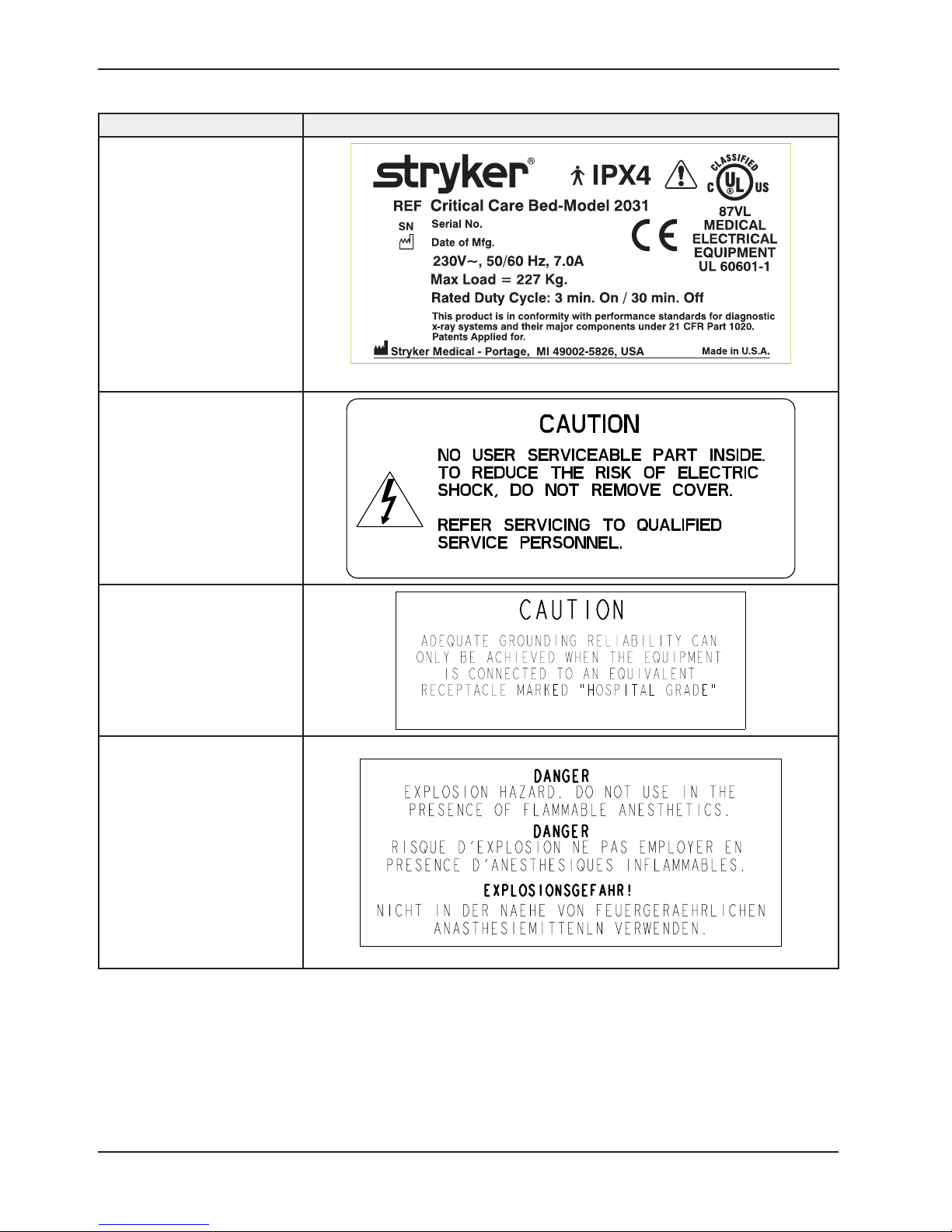
Product Labels
Label Part Number Label
2031-231-128
0988-002-708
1550-090-001
2011-001-104
Return To Table of Contents
4 2031-0 09 -005 REV A www.stryker.com
Page 5
Product Labels
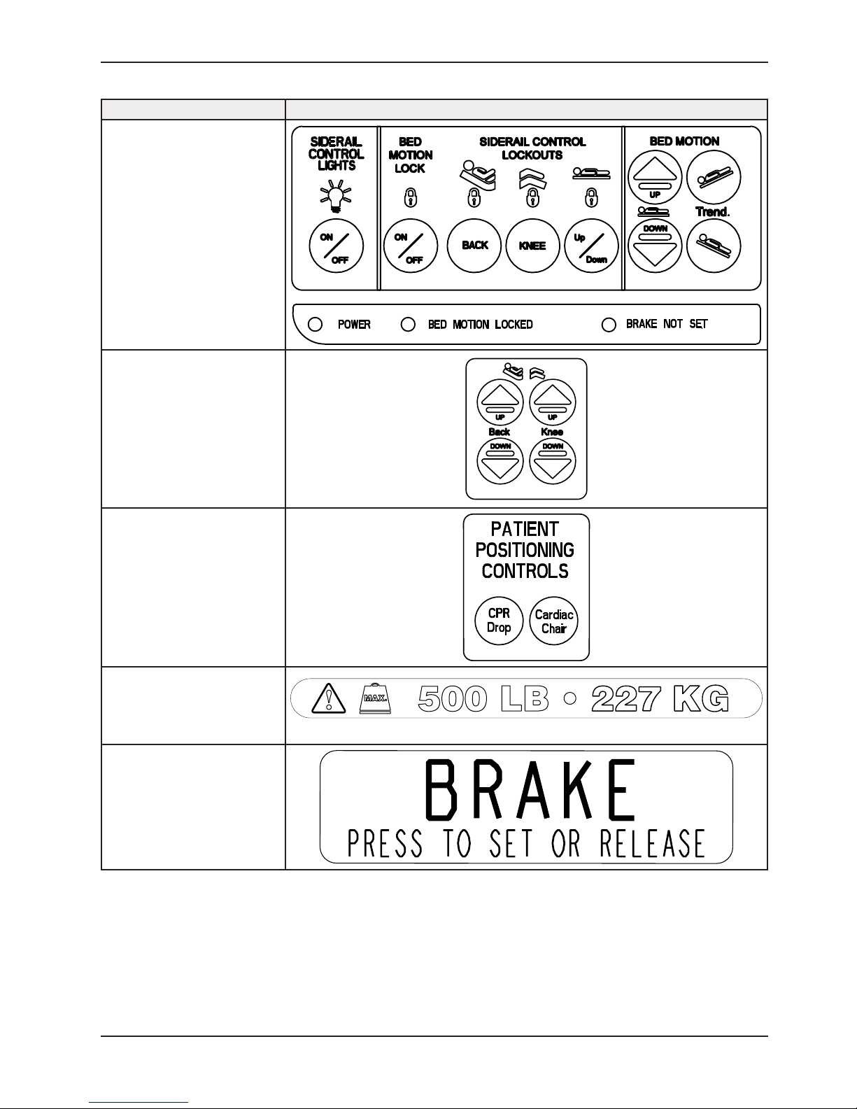
Label Part Number Label
2030-000-151
2035-000-153
2035-000-155
2040-090-100
3000-200-601
www.stryker.com 2031- 00 9-0 05 REV A 5
Return To Table of Contents
Page 6
Product Labels
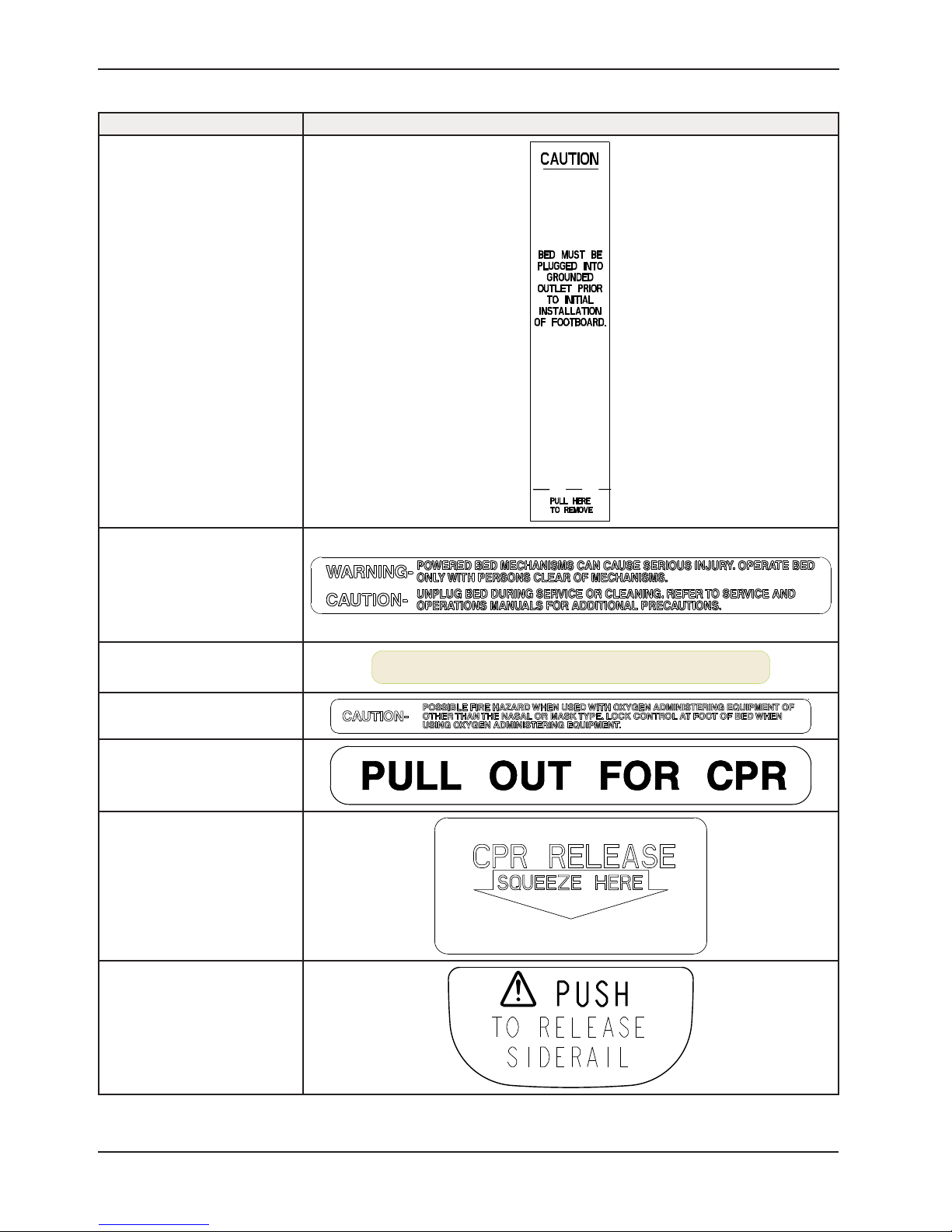
Label Part Number Label
3000-300-641
3000-400-556
3000-500-025
3000-500-029
3000-526-003
3001-300-603
3003-503-901
FOR HOSPITAL STAFF USE ONLY
Return To Table of Contents
6 2031-0 09 -005 REV A www.stryker.com
Page 7
Product Labels
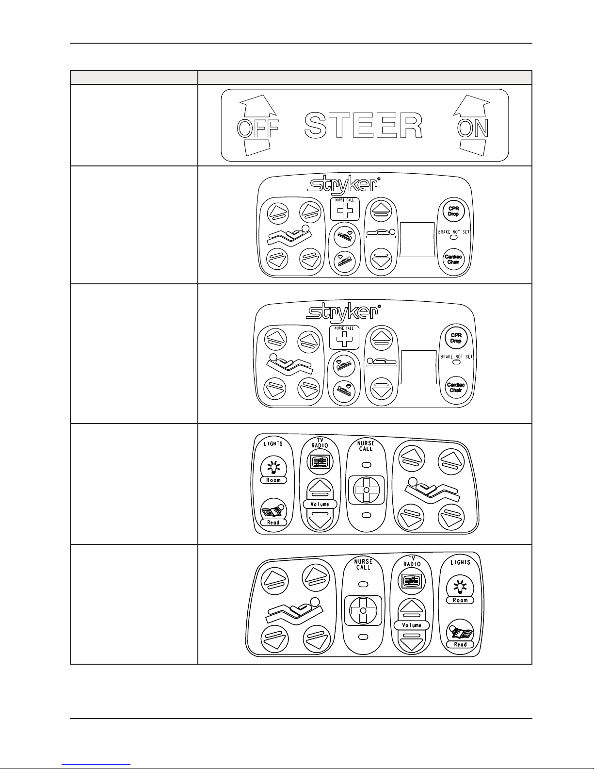
Label Part Number Label
5000-090-013
2030-000-301
2030-000-401
2035-000-102
2035-000-202
www.stryker.com 2031- 00 9-0 05 REV A 7
Return To Table of Contents
Page 8
Product Labels
Label Part Number Label
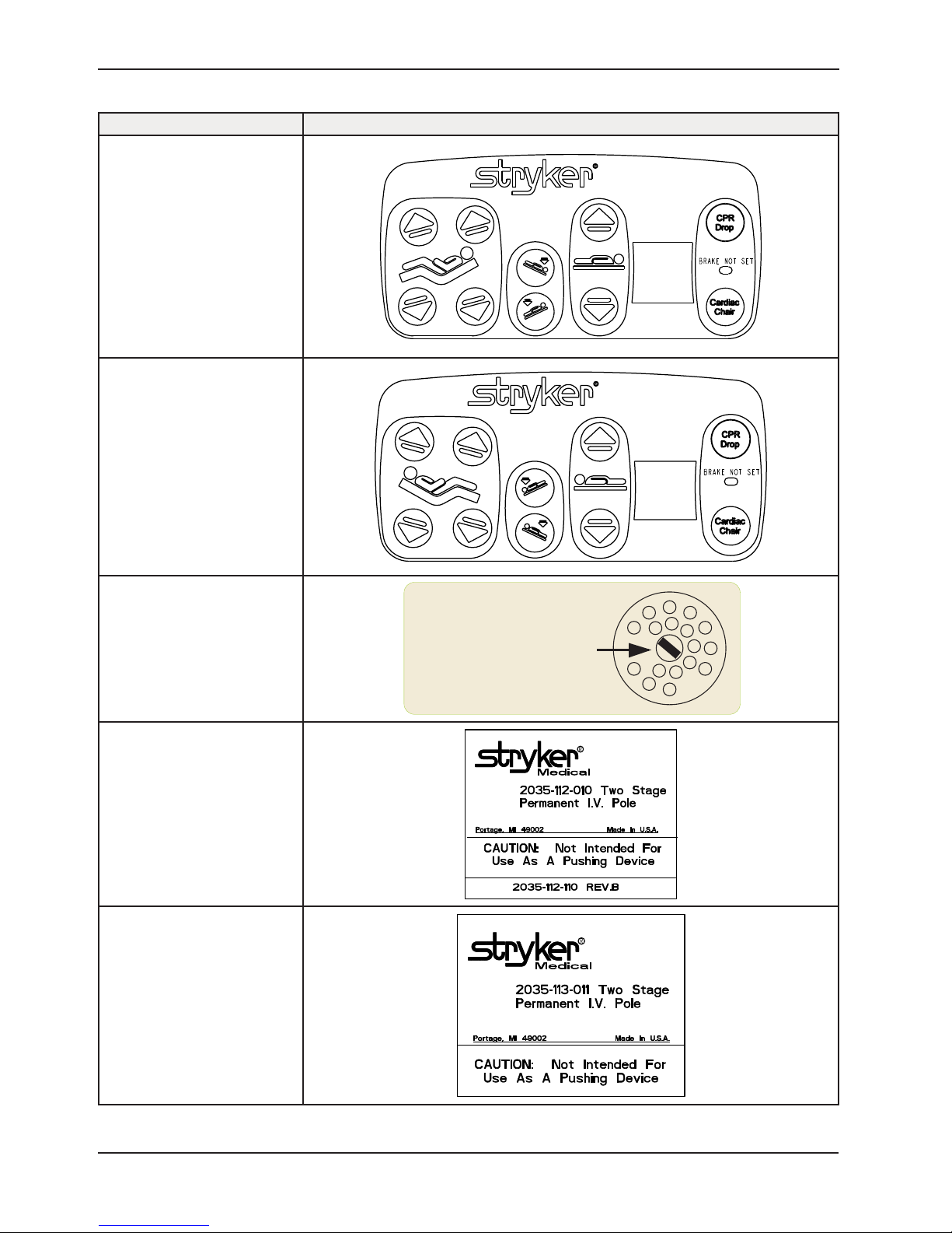
2030-000-300
2030-000-400
5000-090-028
20 3 5-112-110
20 3 5-113 -111
NOTE:
TO PREVENT A LOW BATTERY
CONDITION: WHEN BED IS NOT
PLUGGED IN, POSITION THE CORD
OUT SWITCH TO THE OFF POSITION.
Return To Table of Contents
8 2031-0 09 -005 REV A www.stryker.com
Page 9
Product Labels
Label Part Number Label
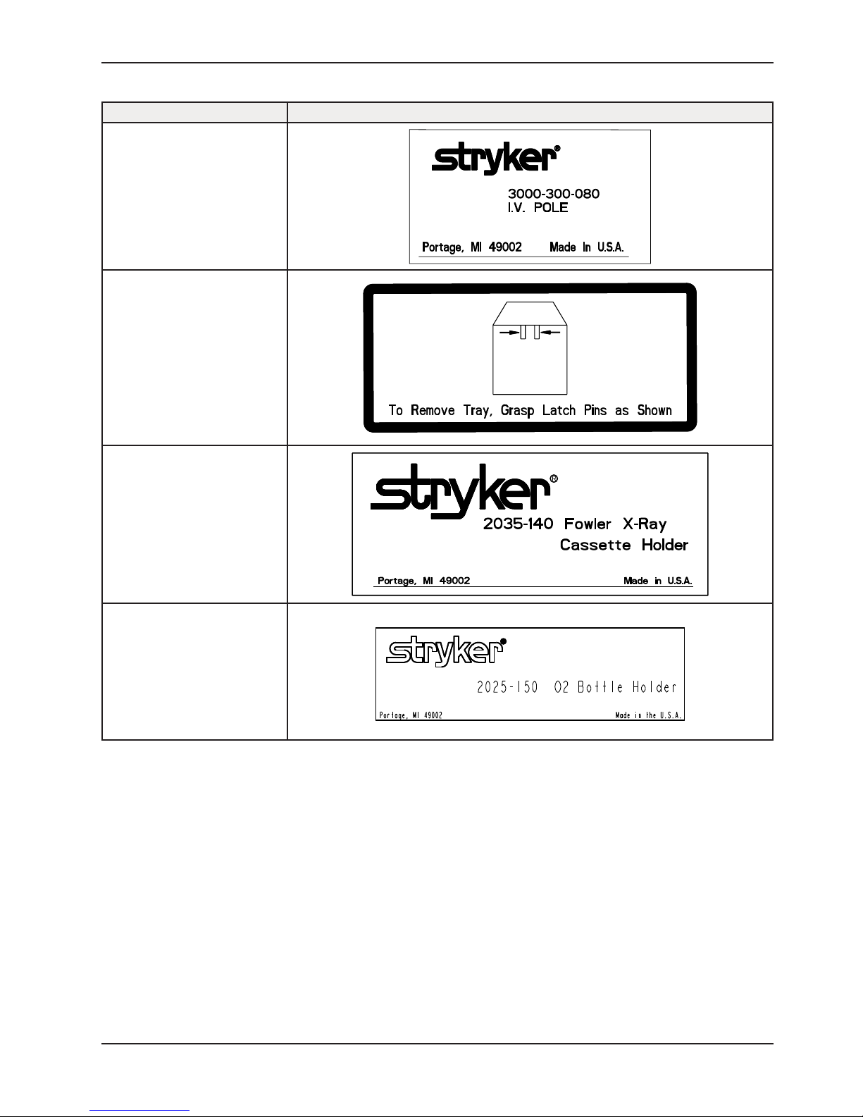
3000-300-089
1010-023-019
2035 -14 0- 0 2 5
2025-150-002
www.stryker.com 2031- 00 9-0 05 REV A 9
Return To Table of Contents
Page 10
Product Labels
Label Part Number Label
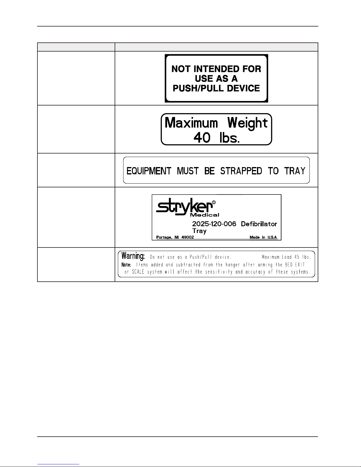
1010-050-019
1010-050-057
2025-120-005
2025-120-006
2030-140-002
Return To Table of Contents
10 2031- 00 9-0 05 REV A www.stryker.com
Page 11
Introduction
Intended Use
This manual is designed to assist you with the operation of the Model 2031 Epic II® Critical Care Bed. Read it thoroughly
before using the equipment.
Specifications
Safe Working Load
Note: Safe Working Load indicates the sum of the
patient, mattress, and accessory weight.
Bed Weight 594 lbs 269 kg
Overall Length/Width Length 91” 231 cm
Width 42.5” 108 cm
Minimum Bed Height 18” 46 cm
Maximum Bed Height (Standard)
Maximum Bed Height (Enhanced)
Fluoroscopy Access Epic II® 17” 43.1 cm
Knee Gatch Angle 0° to 30°
Back Angle 0° to 90°
Trendelenburg/Reverse Trendelenburg -12° to +12° ±2°
Electrical Requirements 230 VAC, 50/60 Hz, 7.0 A
Battery Voltage (1) 9V (Alkaline Battery) - Nurse Call Option
Noise Level < 65 dB
Duty Cycle 3 minutes ON / 30 minutes OFF
Mattress Specifications
Thickness 6” 15. 2 cm
Width >= 35” >= 88.9 cm
Length >= 84” >= 213.4
ILD 80 lbs 36.3 kg
500 lbs 227 kg
30” to 31”
32” to 33”
(Continuous with Intermittent Loading)
76.2 cm to 78.7 cm.
81.2 cm to 83.8 cm.
The above stated mattress specifications assist in ensuring the product conforms to HBSW and IEC
specifications.
Stryker reserves the right to change specifications without notice.
Specifications listed are approximate and may vary slightly from unit to unit or by power supply fluctuations.
www.stryker.com 2031- 00 9-0 05 REV A 11
Return To Table of Contents
Page 12
Introduction
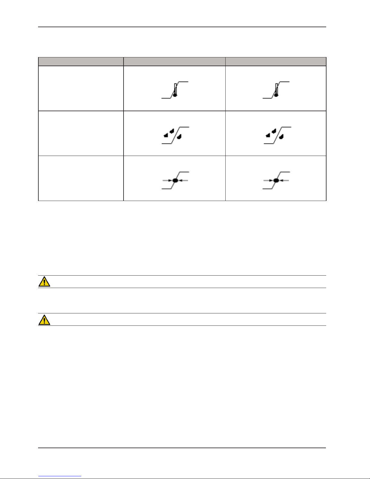
Environmental Conditions
Environmental Conditions Operation Storage and Transportation
40 0C
Ambient Temperature
10 0C
(50 0F)
Relative Humidity
(Non-Condensing)
Atmospheric Pressure
Stryker reserves the right to change specifications without notice.
Specifications listed are approximate and may vary slightly from unit to unit or by power supply fluctuations.
30%
700 hPa
(104 0F)
-30 0C
(-22 0F)
75%
10%
1060 hPa
500 hPa
60 0C
(140 0F)
95%
1060 hPa
Warning/Caution/Note Definition
The words Warning, Caution and Note carry special meanings and should be carefully reviewed.
WARNING
Alerts the reader about a situation, which if not avoided, could result in death or serious injury. It may also describe
potential serious adverse reactions and safety hazards.
CAUTION
Alerts the reader of a potentially hazardous situation, which if not avoided, may result in minor or moderate injury to
the user or patient or damage to the equipment or other property. This includes special care necessary for the safe
and effective use of the device and the care necessary to avoid damage to a device that may occur as a result of use
or misuse.
Note
This provides special information to make maintenance easier or important instructions clearer.
Return To Table of Contents
12 2031-009 -005 REV A www.stryker.com
Page 13
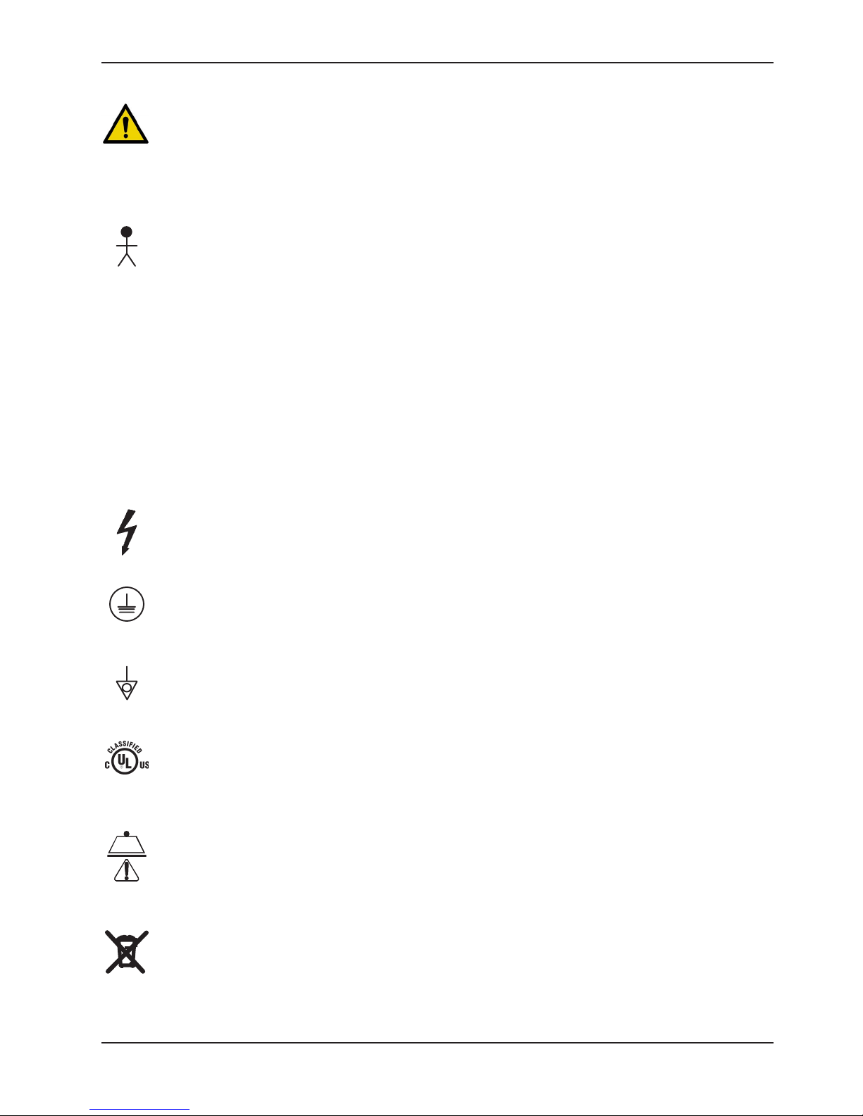
Symbols
Warning/Caution, consult accompanying documentation
~
IPX4
Alternating Current
Type B Equipment: equipment providing a particular degree of protection against electric shock,
particularly regarding allowable leakage current and reliability of the protective earth connection.
Class 1 Equipment: equipment in which protection against electric shock does not rely on BASIC
INSULATION only, but which includes an additional safety precaution in that means are provided for the
connection of the EQUIPMENT to the protective earth conductor in the fixed wiring of the installation in
such a way that ACCESSIBLE METAL PARTS cannot become live in the event of a failure of the BASIC
INSULATION.
Mode of Operation: Continuous
Protection from liquid splash
Dangerous Voltage Symbol
Protective Earth Terminal
Potential Equalization Symbol
Medical Equipment Classified by Underwriters Laboratories Inc. with Respect to Electric Shock, Fire,
Mechanical and Other Specified Hazards Only in Accordance with UL 60601−1, First Edition (2003) and
CAN/CSA C22.2 No. 601.1−M90 with updates 1 and 2 and IEC 60601-1 (1988) with Amendment 1 (1991)
and Amendment 2 (1995), and IEC 60601-2-38 First Edition (1996) with Amendment 1 (1999).
Safe Working Load Symbol
In accordance with European Directive 2002/96/EC on Waste Electrical and Electronic Equipment, this
symbol indicates that the product must not be disposed of as unsorted municipal waste, but should be
collected separately. Refer to your local distributor for return and/or collection systems available in your
country.
www.stryker.com 2031- 00 9-0 05 REV A 13
Return To Table of Contents
Page 14

Safety Tips and Guidelines
Safety Tips and Guidelines
Before operating the Epic II® Critical Care Beds, it is important to read and understand all information in this manual.
Carefully read and strictly follow the safety tips and guidelines listed in this manual.
To ensure safe operation of the bed, methods and procedures must be established for educating and training hospital
staff on the intrinsic risks associated with the usage of electric beds.
WARNING
• When the bed is unplugged, secure the power cord around the head end of the bed to prevent possible fraying of
the power cord due to crushing of the cable between moveable parts, which could result in the risk of electrical
shock.
• The Epic II® Critical Care Bed is equipped with a hospital grade plug for protection against shock hazard. It must
be plugged directly into a properly grounded three-prong receptacle. Grounding reliability can be achieved only
when a hospital grade receptacle is used.
• Serious injury can result if caution is not used when operating the bed. Operate bed only when all persons are
clear of the electrical and mechanical systems.
• To help reduce the number and severity of falls by patients, always leave the bed in the lowest position when the
patient is unattended.
• Always apply the caster brakes when a patient is getting on or off the bed. Always keep the caster brakes applied
when a patient is on the bed (except during transport). Serious injury could result if the bed moves while a patient
is getting in or out of bed. After the brake pedal is applied, push on the bed to ensure the brakes are locked. When
moving the bed, toggle the steer pedal to put the bed in the steer mode. This locks the swivel motion of the right
foot end caster and makes the bed easier to move.
• When raising the siderails, listen for the “click” that indicates the siderail has locked in the up position. Pull firmly
on the siderail to ensure it is locked into position. Siderails are not intended to be a patient restraint device. It is
the responsibility of attending medical personnel to determine the degree of restraint and the siderail positioning
necessary to ensure a patient will remain safely in bed.
• Ensure the brakes are completely released prior to attempting to move the bed. Attempting to move the bed with
the brakes actuated could result in injury to the user and/or patient.
• Assistance is required to lower the Back if the angle of the Back is greater than 80° when the CPR emergency
release is activated. Attempting to lower the Back in this position without assistance may result in injury to the
operator.
• Always unplug bed during service or cleaning. When working under the bed, always place blocks under the litter
frame to prevent injury in case the Bed Down switch is accidently activated.
• Battery posts, terminals and related accessories contain lead and lead compounds, chemicals known to the State
of California to cause cancer and birth defects or other reproductive harm. Wash hands after handling.
• The Epic II® Critical Care Bed is not intended for pediatric use or for patients under 50 pounds.
• Explosion Hazard - do not use bed in the presence of flammable anesthetics.
• To avoid entanglement, possibly resulting in frayed power cords and risk of electrical shock, wrap the bed power
cord around the head board of the bed during transport.
• Service only by qualified personnel. Refer to the maintenance manual. Verify the power cord is unplugged before
servicing.
• When using any mattress and/or mattress overlay that increases the overall height greater than 6" extra caution
and or operator supervision is required to help reduce the likelihood of a patient fall occurring.
• Trendelenburg is not easily achievable when mains voltage has been interrupted.
• When a Patient’s condition (such as disorientation due to medication or clinical condition) could lead to patient
entrapment, the mattress support platform should be left in the flat position while the patient is unattended (except
when required otherwise by medical staff for special or particular circumstances).
Return To Table of Contents
14 2031-009 - 005 REV A www.stryker.com
Page 15

Safety Tips and Guidelines
WARNING (CONTINUED)
To avoid possible injury and to assure proper operation when using model number 2750, 2920, 2950 or 2981 mattress:
• Confirm proper scale system operation following mattress installation. For best results, secure the therapy mattress
power cord to prevent damage to the cord or interference with the bed frame and the scale system.
• Do not zero bed scales or weigh patient with Percussion, Vibration, Rotation or Turn Assist active. Patient motion
and position resulting from the dynamic therapy mattress may adversely affect scale system performance.
• Do no initialize (“arm”) bed exit with Percussion, Vibration, Rotation or Turn Assist active. The patient motion and
position resulting from the dynamic therapy mattress may adversely affect bed exit system performance.
• When using an XPRT (2950), Position PRO (2920), Impression (2981) or Symmetric Aire (2750) mattress, extra
caution and/or operator supervision is required to help reduce the likelihood of a patient fall occurring.
CAUTION
• The lockout buttons on the foot board lock the Fowler, Gatch and Bed Up/Down functions and prevent motion of
the bed. It is the responsibility of attending medical personnel to determine whether these functions should be
locked and to use the buttons accordingly.
• Because individual beds may have different options, foot boards should not be moved from one bed to another.
Mixing foot boards could result in unpredictable bed operation.
• If large fluid spills occur in the area of the circuit boards or motors, immediately unplug the bed power cord from
the wall socket. Remove the patient from the bed and clean up the fluid. Have maintenance completely check the
bed. Fluids can short out controls and may cause the bed to operate erratically or make some functions completely
inoperable. Component failure caused by fluids could even cause the bed to operate unpredictably and could
cause injury to the patient. DO NOT put the bed back into service until it is completely dry and has been thoroughly
tested for safe operation.
• Preventative maintenance should be performed at a minimum of annually to ensure all features are functioning as
designed. Close attention should be given to safety features including, but not limited to:
• Safety side latching mechanisms Caster braking systems
• Leakage current 300 microamps max. No controls or cabling entangled in bed mechanisms
• Frayed electrical cords and components All controls return to off or neutral position when released
• The siderails are not intended to be used as a pushing device. Damage to the siderails could occur.
• The use of a mattress overlay may reduce the effectiveness of the siderail.
• When attaching equipment to the bed, ensure it will not impede normal bed operation or patient injury could occur.
For example: hooks on hanging equipment must not actuate control buttons, equipment must not hide the nurse
call button, etc.
• The weight of the IV bags should not exceed 40 pounds.
• Do not add or remove weight when the bed exit system is armed.
• The cleanliness and integrity of both ground chains must be maintained to minimize static build up and
discharge.
• IV Poles should not be used as a bed push/pull device.
• The safe working load of the defibrillator tray is 40 lbs.
• The safe working load of the oxygen bottle holder is 45 lbs.
• The safe working load of the pump rack holder is 45 lbs.
www.stryker.com 2031- 00 9-0 05 REV A 15
Return To Table of Contents
Page 16

Setup Procedures
Setup Procedures
It is important that the Epic II® Critical Care Bed is working properly before it is put into service. The following list will
help ensure that each part of the bed is checked.
• Plugthebedintoaproperlygrounded,hospitalgradewallreceptacle.
WARNING
The Epic II® Critical Care Bed is equipped with a hospital grade plug for protection against shock hazard. It must be
plugged directly into a properly grounded three-prong receptacle. Grounding reliability can be achieved only when a
hospital grade receptacle is used.
• Depress the pedal at either side of the bed fully to set the four wheel brakes and ensure all four casters lock.
Depress the pedal again to release the brakes.
• Toggle the steer pedal to put the bed in the steer mode and ensure the locking caster engages.
• Ensure the siderails raise and lower smoothly and lock in the up and intermediate positions.
• Run through each function on the foot board control panel and ensure that each is working properly (refer to the
Function Lockout System Usage section).
• Ensure all functions are working properly on the siderail controls.
• Raise the Back up to approximately 60°. Squeeze the CPR release handle and ensure the Back and Knee will drop
with minimal effort.
• If the bed is equipped with the Nurse Call option, verify it is functioning properly prior to patient use.
Return To Table of Contents
16 2031- 00 9-0 05 RE V A www.stryker.com
Page 17

Base Operation Guide
Brake Pedal Operation
WARNING
Always apply the caster brakes when a patient is getting on or off the bed. Push on the bed to ensure the brakes are
securely locked. Always engage the brakes unless the bed is being moved. Injury could result if the bed moves while
a patient is getting on or off the bed.
Ensure the brakes are completely released prior to attempting to move the bed. Attempting to move the bed with the
brakes actuated could result in injury to the user and/or patient.
To activate the brakes, push down once on one of the pedals located at the midpoint of the bed on both sides (identified
by the label at right). The pedal will remain in the lowered position, indicating the brakes are engaged. To disengage
the brakes, push down once and the pedal will return to the upper position.
NOTE
There are LED lights on the outside of the head end siderails
that will blink when the brakes are not engaged only if the bed is
plugged into a wall socket. The brakes will still operate properly
when the bed is not plugged in.
Steer Pedal Operation
The purpose of the steer caster is to help guide the bed along a straight line and to help with pivoting at corners when
the bed is moved.
To activate the steer caster, move the pedal located at the head end of the bed to your left as shown on the label.
NOTE
For proper “tracking” of the steer caster, push the bed
approximately 10 fe et to allow the wheels to face the direction
of travel before engaging the steer pedal. If this is not done,
proper “tracking” will not occur and the bed will be difficult
to steer.
WARNING
To avoid entanglement, possibly resulting in frayed power cords and risk of electrical shock, wrap the bed power cord
around the head board of the bed during transport.
www.stryker.com 2031- 00 9-0 05 REV A 17
Return To Table of Contents
Page 18

Litter Operation Guide
Operating I.V. Poles
To use the 2-Stage Permanently Attached I.V. pole:
Note
The 2-stage permanently attached I.V. pole is an option and may have been
installed at either the head, foot or both ends. The choice was made at the
time the unit was purchased.
1. Lift and pivot the pole from the storage position and push down until it
rests in the receptacle.
2. To raise the height of the pole, pull up on the telescoping portion (A) until
it locks into place at its fully raised position.
3. Rotate the I.V. hangers (B) to desired position and hang I.V. bags.
4. To lower the I.V. pole turn the latch (C) clockwise until section (A) lowers.
Caution
The weight of the I.V. bags should not exceed 40 pounds.
A
C
B
CPR Emergency Release Usage
If the Back and/or Knee is raised and quick access to the patient is needed, squeeze one of the two red emergency
release handles, located under the litter top at the head section on either side of the bed, and the Back and Knee will
lower to a flat position. The handle can be released at any time to stop the Back from lowering.
WARNING
Assistance is required to lower the Back if the angle of the Back is greater than 80° when the CPR emergency release
is activated. Attempting to lower the Back in this position without assistance may result in injury to the operator
CPR Board Usage
The CPR board is stored on the bed’s head board. To remove it, pull it away from the head board and lift it out of the
storage position. The head board can also be removed and used as an emergency CPR board.
Foley Bag Hooks Usage
The standard Foley bag hooks are found at two locations on both sides of the bed, under the frame rail below the seat
section and at the extreme foot end of the bed. The patient weight reading on the bed scale system will not be affected
when the Foley bag hooks are used.
Return To Table of Contents
18 2031- 00 9-0 05 RE V A www.stryker.com
Page 19

Siderail Operation Guide
Positioning Siderails
NOTE
The head end siderails can be locked at two positions (intermediate & full). The foot end siderails lock in the full up
position only.
• The siderails can slide to the side of the bed when not in use. To remove the rail from the tucked position, grasp
the top of the rail and pull outward.
• To engage the head end siderail, grasp the rail and swing it upward to full height. When the siderail is being raised,
it does not lock in the intermediate position. To lower the siderail, push in the yellow release handle and rotate the
siderail until it locks in the intermediate position. To lower the siderail fully, push in the yellow release handle again
and rotate the siderail until it is completely lowered.
NOTE
To activate the siderail bypass mechanism, the rail must be fully lowered. If the rail is not completely lowered, the
siderail will lock in the intermediate position when it is raised. There is no intermediate level and thus no bypass function
on the foot end siderails.
• To engage the foot end siderail, the same procedure is required as for the head end siderail, however, the siderail
swings toward the foot end of the bed.
WARNING
When raising the siderails, listen for the “click” that indicates the siderail has locked in the up position. Pull firmly
on the siderail to ensure it is locked into position. Siderails are not intended to be a patient restraint device. It is the
responsibility of attending medical personnel to determine the degree of restraint and the siderail positioning necessary
to ensure a patient will remain safely in bed.
CAUTION
• The siderails are not intended to be used as a pushing device. Damage to the siderails could occur.
• The use of a mattress overlay may reduce the effectiveness of the siderail.
Siderail Control Panel Lights
• The head end siderails are equipped with lights to illuminate the siderail control buttons and the nurse call switch.
The lights are activated at the foot board control panel.
• There are three settings for the intensity of the siderail control lights: low, medium and high. When all the siderail
lights are off, push the siderail control light button on the foot board once to turn on both the control lights and the
nurse call indicator light. Push the button again to change the siderail control lights from low to medium setting,
and again to change to the high setting. (The intensity of the nurse call indicator light does not change.)
• When all the siderail lights are on, pushing the button once will turn off only the siderail control lights and pushing
it again will turn off the nurse call indicator light (see control panel guide page 23).
CAUTION
The nurse call indicator light on the siderails helps ensure the patient understands where the button is for contacting
the nurse station. Turning this light off will compromise this ability, especially in a darkened room.
www.stryker.com 2031- 00 9-0 05 REV A 19
Return To Table of Contents
Page 20

Outside Standard Siderail
Siderail Operation Guide
21
3
1. Press to raise back section.
2. Press to raise knee section.
3. Press to lower back section.
4. Press to lower knee section.
5. Press to lower the head end of the bed (Trendelenburg).
6. Press to lower the foot end of the bed (Reverse Trendelenburg).
7. Press to raise the litter. If your bed is equipped with the enhanced height option, continue to hold the button an
additional 5 seconds after the first stop. The litter will raise an additional 2 inches.
8. Press to lower the litter.
9. Press to activate emergency CPR positioning.
10. Press to activate Cardiac Chair positioning.
4
5
6
7
8
9
LED Light
“Brake Not Set”
10
CAUTION
When attaching equipment to the bed, ensure it will not impede normal bed operation or patient injury could occur.
For example: hooks on hanging equipment must not actuate control buttons, equipment must not hide the nurse call
button, etc.
Return To Table of Contents
20 2031- 00 9-0 05 REV A www.stryker.com
Page 21

Siderail Operation Guide
Outside Siderail with Optional Nurse Call
21
3 4
1. Press to raise back section.
2. Press to raise knee section.
3. Press to lower back section.
4. Press to lower knee section.
5. Press to activate the nurse call.
6. Press to lower the head end of the bed (Trendelenburg).
7. Press to lower the foot end of the bed (Reverse Trendelenburg).
8. Press to raise the litter. If your bed is equipped with the enhanced height option, continue to hold the button an
additional 5 seconds after the first stop. The litter will raise an additional 2 inches.
9. Press to lower the litter.
10. Press to activate emergency CPR positioning.
11. Press to activate Cardiac Chair positioning.
5
6
7
8
9
10
LED Light
“Brake Not Set”
11
CAUTION
When attaching equipment to the bed, ensure it will not impede normal bed operation. For example: hooks on hanging
equipment must not actuate control buttons, equipment must not hide the nurse call button, etc.
www.stryker.com 2031- 00 9-0 05 REV A 21
Return To Table of Contents
Page 22

Siderail Operation Guide
Inside Siderail with Optional Nurse Call and Communications
1
3 4
1. Press to raise knee section.
2. Press to raise back section.
3. Press to lower knee section.
4. Press to lower back section.
5. Press to activate the nurse call.
6. Press to turn the TV/Radio on. Press again to turn off the TV/Radio.
7. Press to increase the TV or radio volume.
8. Press to decrease the TV or radio volume.
9. Press to turn on the room lights. Press again to turn off.
10. Press to turn on the reading light. Press again to turn off.
2
5 6
7
9
8
10
CAUTION
When attaching equipment to the bed, ensure it will not impede normal bed operation. For example: hooks on hanging
equipment must not actuate control buttons, equipment must not hide the nurse call button, etc.
Return To Table of Contents
22 2031- 00 9-0 05 REV A www.stryker.com
Page 23

Foot Board Operation Guide
Foot Board Control Panel Guide
1. Press repeatedly for low, medium and high settings for the siderail control lights. Continue to press this switch to
turn off the siderail control lights and the nurse call indicator light (see page 21).
2. Press to lock out all bed motion controls on the siderails. Press again to unlock.
3. Press to lock out Back motion control on the siderails. Press again to unlock.
4. Press to lock out Knee motion control on the siderails. Press again to unlock.
5. Press to lock out bed up/down motion controls on the siderails. Press again to unlock.
6. Press to raise the bed height. If your bed is equipped with the enhanced height option, continue to hold the button
an additional 5 seconds after the first stop. The litter will raise an additional 2 inches.
7. Press to lower bed.
8. Press to lower head end of bed (Trendelenburg).
9. Press to lower foot end of bed (Reverse Trendelenburg).
CAUTION
When attaching equipment to the bed, ensure it will not impede normal bed operation or patient injury could occur.
For example: hooks on hanging equipment must not actuate control buttons, equipment must not hide the nurse call
button, etc.
Because individual beds may have different options, foot boards should not be moved from one bed to another. Mixing
foot boards could result in unpredictable bed operation.
Return To Table of Contents
www.stryker.com 2031- 00 9-0 05 REV A 23
Page 24

Foot Board Operation Guide
Foot Board Control Panel Guide (Continued)
LED Display Panel Guide
The LED DIsplay Panel is located at the foot end of the bed, below the Control Panel.
• “POWER” - will light when the bed is plugged into the wall receptacle or the battery power switch is on. Will blink
if the 9V Nurse Call battery needs to be replaced.
• “BED MOTION LOCKED” - will light when the Bed Motion Lock has been activated.
Function Lockout System Usage
1. To lock out all bed motion switches on the bed, press the “ON/OFF” switch in the “Siderail Control Lockouts”
module. The padlock” symbol on the control panel will be lighted when that function is locked out.
2. To lock out the bed movement functions on the siderails and prevent the patient from changing the positioning of
the bed, press the “BACK” or “KNEE” switch in the “Siderail Control Lockouts” module. The “padlock” symbol on
the control panel will be lighted when that function is locked out.
3. To lock out the bed up/down motion on the siderails, press the Up/Down switch in the “Siderail Control Lockouts”
module. The “padlock” symbol on the control panel will be lighted when that function is locked out.
CAUTION
The lockout buttons on the foot board lock the Fowler, Gatch and Bed Up/Down functions and prevent motion of the
bed. It is the responsibility of attending medical personnel to determine whether these functions should be locked and
to use the buttons accordingly.
Return To Table of Contents
24 2031- 00 9- 005 REV A www.stryker.com
Page 25

Foot Board Operation Guide
Foot Board Control Panel Guide (Continued)
1. Press to raise back section.
2. Press to raise knee section.
3. Press to lower back section.
4. Press to lower knee section.
1. Press to activate the emergency CPR drop function. The bed will level from Trendelenburg/reverse Trendelenburg,
the Fowler will lower to flat, the Knee will lower to flat and the litter will lower to full down.
2. Press to activate the Cardiac Chair function. The Knee will raise, the Fowler will raise or lower to approximately
52° and the bed will tilt to approximately –12° reverse Trendelenburg (foot end down) or –14° if the bed has the
enhanced height option. Release the button to stop bed movement: hold the button until movement stops to
complete the function.
www.stryker.com 2031- 00 9-0 05 REV A 25
Return To Table of Contents
Page 26

Notes
Return To Table of Contents
26 2031- 009-0 05 RE V A www.stryker.com
Page 27

Preventative Maintenance
WARNING
Service only by qualified personnel. Refer to the maintenance manual. Verify the power cord is unplugged before
servicing.
Nurse Call Battery
• To prevent a low battery condition when the bed is not plugged in, position the cord out switch at the head end
of the bed to the off position. The switch is identified by the label shown below. If the switch is not positioned
as shown below and the bed power cord and pendant cord are unplugged, the life of the back-up battery will be
significantly reduced.
• If the power light (located on the foot board) is flashing, the Nurse Call battery needs to be replaced. The battery
is located on the patient’s left side at the head end of the bed. No tools are required to replace the battery. Unplug
the bed power cord from the wall socket and replace the battery. Properly dispose of the old battery in accordance
with local regulations.
Main Bed Power Circuit Breaker
In the event of a loss of bed functions, unplug the bed power cord from the wall socket and reset the circuit breaker(s)
located under the bed on the patient’s left side. Plug the bed into a properly grounded wall receptacle and follow the
setup procedures listed on page 16.
www.stryker.com 2031- 00 9-0 05 REV A 27
Return To Table of Contents
Page 28

Preventative Maintenance
Beds require an effective maintenance program, we recommend checking these items annually. Use this sheet for
your records. Keep on file.
Checklist
_____ All fasteners secure.
__ ___ Engage brake pedal and push on the frame to ensure all casters lock securely.
__ ___ Inspect the brake assembly (Brake Cam, Brake Plate Body, Brake Ratchet Spring and Brake Bar) for
degradation or signs of wear at the foot end and head end of the bed. Ensure brake assembly components
are functioning properly.
_____ Locking steer caster engages and disengages properly - optional equipment.
__ ___ Siderails move, latch and stow properly.
__ ___ All functions on siderails working properly (including LED’s).
__ ___ Manual CPR release working properly.
__ ___ Optional foot prop intact and working properly.
__ ___ I.V. pole working properly.
__ ___ Foley bag hooks intact.
__ ___ Chart rack intact and working properly.
__ ___ CPR board not cracked or damaged and stores properly.
__ ___ No cracks or splits in head and foot boards.
__ ___ All functions on footboard working properly (including LED’s).
__ ___ No rips or cracks in mattress cover.
__ ___ Power cord and plug not frayed or damaged.
__ ___ No cables worn or pinched.
_____ All electrical connections tight.
__ ___ All grounds secure to the frame.
_____ Ground impedance not more than 100 milliohms.
_____ Current leakage not more than 300 microamps.
__ ___ Apply grease to the bed grease points including the fowler clutch and brake cam.
__ ___ Ensure ground chains are clean, intact, and have at least two links touching the floor.
_____ Optional accessories intact and working properly.
__ ___ Fowler functioning properly.
__ ___ Motion interrupt switches working properly.
__ ___ Check all motion functionality.
_____ Check nurse call functionality.
_____ Check Nurse Call battery - optional equipment.
__ ___ Check labels, as specified in the Operations and manuals to ensure legibility, proper adherence and
integrity.
Bed Serial Number:
Completed by: _______________________________________ Date: _________________
Return To Table of Contents
28 2031- 009-0 05 RE V A www.stryker.com
Page 29

Cleaning
Hand wash all surfaces of the bed with warm water and mild detergent. DRY THOROUGHLY. Do not steam clean or
hose off the Epic II Bed. Do not immerse any part of the bed. Some of the internal parts of the bed are electric and
may be damaged by exposure to water.
Suggested cleaners for bed surfaces:
Quaternary Cleaners (active ingredient − ammonium chloride) (excluding Virex® TB)
Phenolic Cleaners (active ingredient − o−phenylphenol)
Chlorinated Bleach Solution (5.25% − less than 1 part bleach to 100 parts water)
Avoid over saturation and ensure the product does not stay wet longer than the chemical manufacturer’s guidelines
for proper disinfecting.
CAUTION
SOME CLEANING PRODUCTS ARE CORROSIVE IN NATURE AND MAY CAUSE DAMAGE TO THE PRODUCT IF
USED IMPROPERLY. If the products described above are used to clean Stryker patient care equipment, measures
must be taken to insure the beds are wiped with a damp cloth soaked in clean water and thoroughly dried following
cleaning. Failure to properly rinse and dry the beds will leave a corrosive residue on the surface of the bed, possibly
causing premature corrosion of critical components. Failure to follow the above directions when using these types of
cleaners may void this product’s warranty.
For mattress cleaning instructions, please see the tag on the mattress, or contact the mattress manufacturer.
Clean Velcro® AFTER EACH USE. Saturate Velcro® with disinfectant and allow disinfectant to evaporate. (Appropriate
disinfectant for nylon Velcro® should be determined by the hospital.
Virex® TB is not an approved cleaning agent for this product. Do not use for bed cleaning.
www.stryker.com 2031- 00 9-0 05 REV A 29
Return To Table of Contents
Page 30

Warranty
Limited Warranty
Stryker Medical Division, a division of Stryker Corporation, warrants to the original purchaser the 2031 Epic II® Critical
Care Bed to be free from defects in material and workmanship for a period of One (1) years after date of delivery.
Stryker’s obligation under this warranty is expressly limited to supplying replacement parts and labor for, or replacing,
at its option, any product which is, in the sole discretion of Stryker, found to be defective. If requested by Stryker,
products or parts for which a warranty claim is made shall be returned prepaid to the factory. Any improper use or
any alteration or repair by others in such manner as in Stryker’s judgment affects the product materially and adversely
shall void this warranty. Any repair of Stryker products using parts not provided or authorized by Stryker shall void this
warranty. No employee or representative of Stryker is authorized to change this warranty in any way.
Stryker Medical Bed products are designed for a 15 year expected service life under normal use, conditions, and with
appropriate periodic maintenance as described in the maintenance manual for each device. Stryker warrants to the
original purchaser that the welds on its Bed products will be free from structural defects for the expected 15 year life
of the Bed product as long as the original purchaser owns the product.
This statement constitutes Stryker’s entire warranty with respect to the aforesaid equipment. Stryker makes no
other warranty or representation, either expressed or implied, except as set forth herein. There is no warranty
of merchantability and there are no warranties of fitness for any particular purpose. In no event shall Stryker be
liable here under for incidental or consequential damages arising from or in any manner related to sales or use of
any such equipment.
To Obtain Parts and Service
Stryker products are supported by a nationwide network of dedicated Stryker Field Service Representatives. These
representatives are factory trained, available locally, and carry a substantial spare parts inventory to minimize
repair time. Simply call your local representative, or call Stryker Customer Service USA at 1-800-327−0770,
Canada 1-888-233-6888.
Return Authorization
Merchandise cannot be returned without approval from the Stryker Customer Service Department. An authorization
number will be provided which must be printed on the returned merchandise. Stryker reserves the right to charge
shipping and restocking fees on returned items. Special, modified, or discontinued, items not subject to return.
Damaged Merchandise
ICC Regulations require that claims for damaged merchandise must be made with the carrier within fifteen (15) days of
receipt of merchandise. Do not accept damaged shipments unless such damage is noted on the delivery receipt at
the time of receipt. Upon prompt notification, Stryker will file a freight claim with the appropriate carrier for damages
incurred. Claim will be limited in amount to the actual replacement cost. In the event that this information is not received
by Stryker within the fifteen (15) day period following the delivery of the merchandise, or the damage was not noted on
the delivery receipt at the time of receipt, the customer will be responsible for payment of the original invoice in full.
Claims for any short shipment must be made within thirty (30) days of invoice.
International Warranty Clause
This warranty reflects U.S. domestic policy. Warranty outside the U.S. may vary by country. Please contact your local
Stryker Medical representative for additional information.
Return To Table of Contents
30 2031- 009- 005 REV A ww w.stryker.com
Page 31

EMC Information
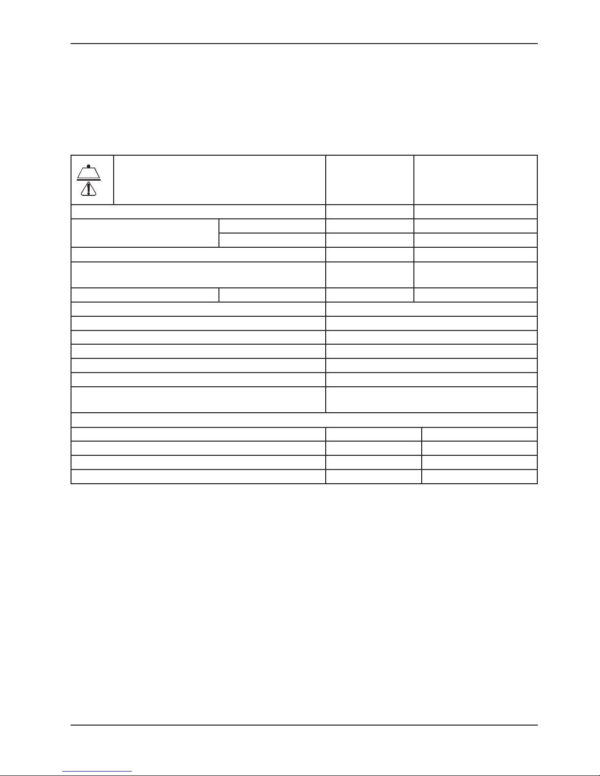
EPIC II CRITICAL CARE BED
Guidance and Manufacturer’s Declaration - Electromagnetic Immunity
The Epic II Critical Care Bed is suitable for use in the electromagnetic environment specified below. The customer
or the user of the Epic II Critical Care Bed should assure that it is used in such an environment.
Immunity Test IEC 60601 Test Level Compliance Level
Electrostatic Discharge (ESD)
IEC 61000-4-2
Electrostatic fast
Transient/burst
IEC61000-4-4
Surge
IEC 61000-4-5
Voltage dips, voltage
variations and short
interruptions on power supply
input lines
IEC 61000-4-11
Power frequency (50/60 Hz)
magnetic field
IEC 61000-4-8
Note: UT is the a.c. mains voltage prior to applications of the test level.
+6 kV contact
+8 kV air
+2 kV for power
supply lines
+1 kV for input/
output lines
+8 kV differential mode
+2 kV common mode
<5%Ut (95% dip in Ut) for
0,5 cycle
40%Ut (60% dip in Ut) for
5 cycles
70%Ut (30% dip in Ut) for
25 cycles.
<5% Ut (>95% dip in Ut)
for 5 sec.
3 A/m 3 A/m Power frequency magnetic
+6 kV contact
+8 kV air
+2 kV for power
supply lines
+1 kV for input/
output lines
+8 kV differential mode
+2 kV common mode
<5%Ut (95% dip in Ut)
for 0,5 cycle
40%Ut (60% dip in Ut)
for 5 cycles
70%Ut (30% dip in Ut)
for 25 cycles.
<5% Ut (>95% dip in Ut)
for 5 sec.
Electromagnetic
Environment Guidance
Floors should be wood,
concrete, or ceramic tile.
If floors are covered with
synthetic material, the relative
humidity should be at least
30%.
Main power quality should be
that of a typical commercial or
hospital environment.
Main power quality is that of
a typical commercial and/or
hospital environment.
Main power quality should be
that of a typical commercial
and/or hospital environment. If
the user of the Epic II Critical
Care Bed requires continued
operation during power main
interruptions, it is recommended
that the device be powered
from an uninterrupted power
supply or a battery.
fields should be at levels
characteristic of a typical
location in a typical commercial
and/or hospital environment.
www.stryker.com 2031- 00 9-0 05 REV A 31
Return To Table of Contents
Page 32

EMC Information
EPIC II CRITICAL CARE BED (CONTINUED)
Recommended separation distances between portable and mobile RF
communications equipment and the Epic II Critical Care Bed.
The Epic II Critical Care Bed is intended for use in an electromagnetic environment in which radiated RF
disturbances are controlled. The customer or the user of the Epic II Critical Care Bed can help prevent
electromagnetic interferences by maintaining a minimum distance between portable and mobile RF
communications equipment (transmitters) and the Epic II Critical Care Bed as recommended below, according
to the maximum output power of the communications equipment.
Rated maximum output
power of transmitter
W
150 kHz to 80 MHz
0,01 0,12 0,12 0,23
0,1 0,38 0,38 0,73
Separation distance according to frequency of transmitter
m
d=1,2
80 MHz to 800 MHz
d=1,2
800 MHz to 2,5 GHz
d=2,3
1 1,2 1,2 2,3
10 3,8 3,8 7,3
100 12 12 23
For transmitters rated at a maximum output power not listed above, the recommended separation distance d in meters
(m) can be estimated using the equation applicable to the frequency of the transmitter, where P is the maximum
output power rating of the transmitter in watts (W) according to the transmitter manufacturer.
Note 1
At 80 MHz and 800 MHz, the separation distance for the higher frequency range applies.
Note 2
These guidelines may not apply in all situations. Electromagnetic propagation is affected by absorption and reflection
from structures, objects and people.
Return To Table of Contents
32 2031- 009-0 05 RE V A www.stryker.com
Page 33

EMC Information
EPIC II CRITICAL CARE BED (CONTINUED)
The Epic II Critical Care Bed is suited for use in the electromagnetic environment specified below. The
customer or the user of the Epic II Critical Care Bed should assure that it is used in such an environment.
Immunity Test IEC 60601 Test Level
Compliance
Level
Electromagnetic Environment - Guidance
Portable and mobile RF communications
equipment should be used no closer to any part
of the Epic II Critical Care Bed, including cables,
than the recommended separation distance
calculated from the equation appropriate for the
frequency of the transmitter.
Recommended Separation Distance
Conducted
RF
IEC 61000-4-6
Radiated RF
IEC 61000-4-3
3 Vrms
150 kHz to 80 MHz
3 V/m
80 MHz to 2,5 GHz
3 Vrms
3 V/m
d=1,2
d=1,2
80 MHz to 800 MHz
d=2,3
800 MHz to 2,5 GHz
where P is the maximum output power rating
of the transmitter in watts (W) according to the
transmitter manufacturer and d is the recommended separation distance in metres (m).
Field strengths from fixed RF transmitters, as
determined by an electromagnetic site survey,a
should be less than the compliance level in each
frequency range.
b
Interference may occur in the vicinity of
equipment marked with the following symbol:
Note 1
At 80 MHz and 800 MHz, the higher frequency range applies.
Note 2
These guidelines may not apply in all situations. Electromagnetic propagation is affected by absorption and reflection
from structures, objects and people.
a
Field strengths from fixed transmitters, such as base stations for radio (cellular/cordless) telephones and land
mobile radios, amateur radio, AM and FM radio broadcast, and TV broadcast cannot be predicted theoretically with
accuracy. To assess the electromagnetic environment due to fixed RF transmitters, an electromagnetic site survey
should be considered. If the measured field strength in the location in which the Epic II Critical Care Bed is used
exceeds the applicable RF compliance level above, the Epic II Critical Care Bed should be observed to verify normal
operation. If abnormal performance is observed, additional measures may be necessary, such as reorienting or
relocating the Epic II Critical Care Bed.
b
Over the frequency range 150 kHz to 80 MHz, field strengths are less than 3 V/m.
www.stryker.com 2031- 00 9-0 05 REV A 33
Return To Table of Contents
Page 34

EMC Information
EPIC II CRITICAL CARE BED (CONTINUED)
Guidance and Manufacturer’s declaration - Electromagnetic Emissions
The Epic II Critical Care Bed is intended for use in an electromagnetic environment specified below. The
customer or the user of the Epic II Critical Care Bed should assure that it is used in such an environment.
Emissions Test Compliance Electromagnetic Environment
The Epic II Critical Care Bed uses RF energy only for its
RF Emissions
CI S PR 11
RF Emissions
CI S PR 11
Group 1
Class A
internal function. Therefore, its RF emissions are very
low and are not likely to cause any interference in nearby
electronic equipment.
The Epic II Critical Care Bed is suitable for use in all
establishments other than domestic and those directly
connected to the public low voltage power supply network
that supplies buildings used for domestic purposes.
Harmonic Emissions
IEC 61000-3-2
Voltage Fluctuations
Flicker Emissions
IEC 61000-3-3
Class A
Complies
Return To Table of Contents
32 2031- 009-0 05 RE V A www.stryker.com
Page 35

2031-400-105 / 2031-400-205
Recycling Passport
A
A 2035-400-900 2
www.stryker.com 2031- 00 9-0 05 REV A 33
Return To Table of Contents
Page 36

2031-400-105 & 2031-400-205
Recycling Passport
A
A 3001-400-930 2
Return To Table of Contents
34 2031- 00 9-0 05 RE V A www.stryker.com
Page 37

2032-135-010
A
Recycling Passport
B
A 2032-235-010 1
B 2025-136-021 1
www.stryker.com 2031- 00 9-0 05 REV A 35
Return To Table of Contents
Page 38

2031-030-201 / 2031-030-205
Recycling Passport
B
A 3002- 4 07-950 1
B 0059-157-000 1
C 3000-303-871 1
A
C
Return To Table of Contents
36 2031- 009- 005 REV A www.stryker.com
Page 39

2031-030-204
Recycling Passport
A 3001-314 -920 1
www.stryker.com 2031- 00 9-0 05 REV A 37
A
Return To Table of Contents
Page 40

Page 41

UNITED STATES
Stryker Medical
3800 E. Centre Ave.,
Portage, Michigan USA
49002
CANADA
Stryker Canada
45 Innovation Drive
Hamilton, Ontario Canada
L9H 7L8
EC REP
EC REP
European Representative
European Representative
Stryker France
Stryker France
ZAC Satolas Green Pusignan
ZAC Satolas Green Pusignan
Av. De Satolas Green
Av. De Satolas Green
69881 MEYZIEU Cedex
69881 MEYZIEU Cedex
France
France
2006/X X XXXX-XXX-XXX REV X www.stryker.com
2010/0 9 2031-009-005 REV A www.stryker.com
UNITED STATES
Stryker Medical
3800 E. Centre Ave.,
Portage, Michigan USA
49002
 Loading...