

Page 1
2017/12 836002-5210 V3.4 www.stryker.com
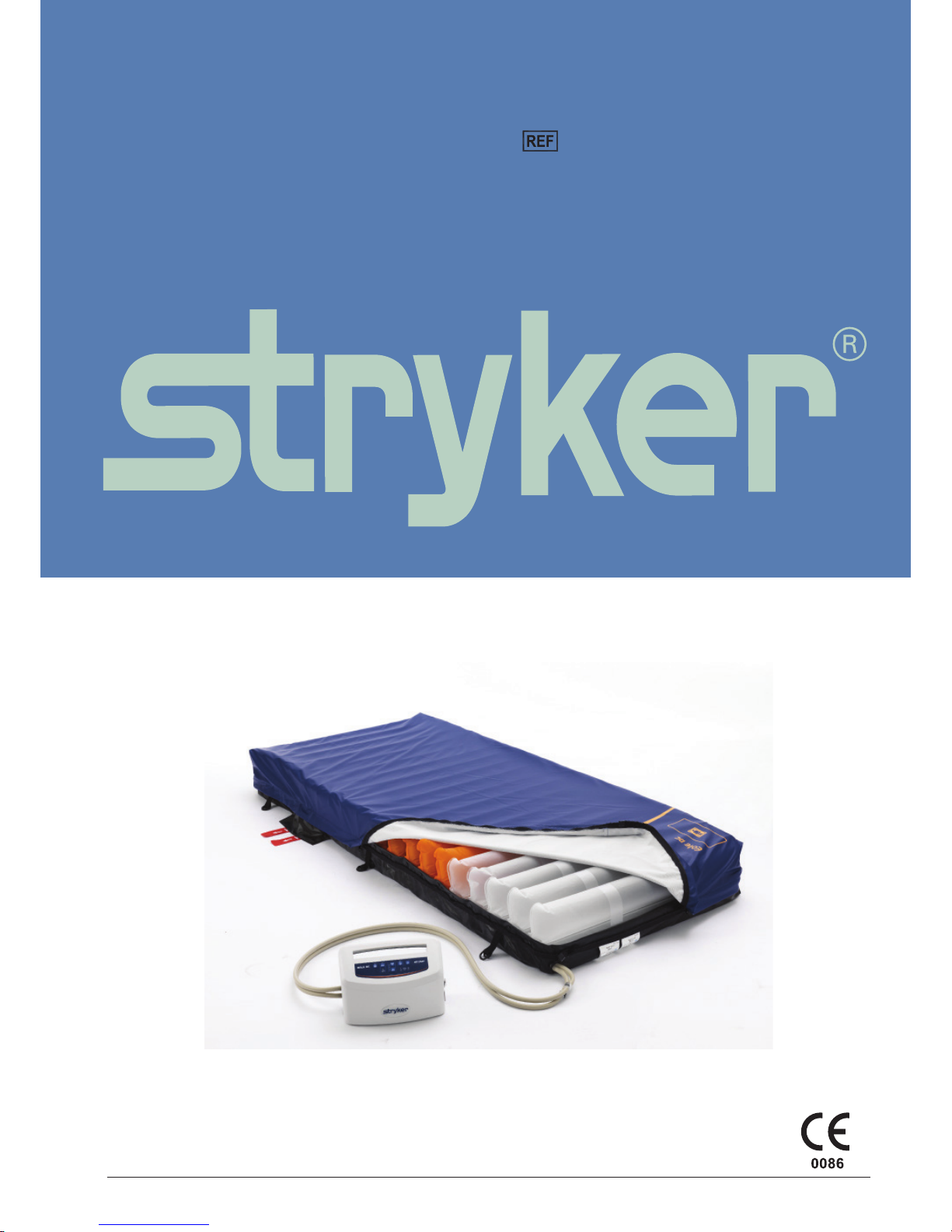
EOLE DC Powered Support Surface
2871
Operations/Maintenance Manual
Page 2

Page 3

www.stryker.com 836002-5210 V3.4 3
Table of Contents
Symbols and Denitions................................................................ 4
Symbols ......................................................................... 4
Warning/Caution/Note Denition ...................................................... 5
Technical Specication................................................................. 6
Introduction.......................................................................... 7
Contraindications.................................................................. 7
Intended Use of Product ............................................................ 7
Expected Service Life .............................................................. 7
Product Description ................................................................ 7
Contact Information ................................................................ 7
Product Serial Number Location/Identication ........................................... 8
Summary of Safety Precautions.......................................................... 9
Product Description .................................................................. 10
Control Unit Front................................................................. 10
Control Unit Rear ................................................................. 10
Control Panel .................................................................... 10
Instructions ..........................................................................11
Installing the Control Unit............................................................11
Product Functions ................................................................ 12
Transport mode .................................................................. 13
Storage ........................................................................ 13
Cleaning and Disinfection.............................................................. 14
Troubleshooting ..................................................................... 15
Service Information .................................................................. 16
Top Cover Replacement ........................................................... 16
Air Cell Replacement .............................................................. 16
Control Unit Replacement .......................................................... 16
Hose Replacement ............................................................... 16
CPC Tube Replacement ........................................................... 16
Filter Replacement................................................................ 16
Preventive Maintenance............................................................... 17
Checklist ....................................................................... 17
Appendix A: EMC Information .......................................................... 19
Guidance and Manufacturer’s Declaration- Electromagnetic Emissions: ...................... 19
Guidance and Manufacturer’s Declaration- Electromagnetic Immunity: ....................... 20
Warranty........................................................................... 22
Limited Warranty ................................................................. 22
To Obtain Parts and Service ........................................................ 22
Return Authorization .............................................................. 22
Damaged Merchandise ............................................................ 22
International warranty clause........................................................ 22
Page 4
4 836002-5210 V3.4 www.stryker.com
Return To Table of Contents
Symbols and Denitions
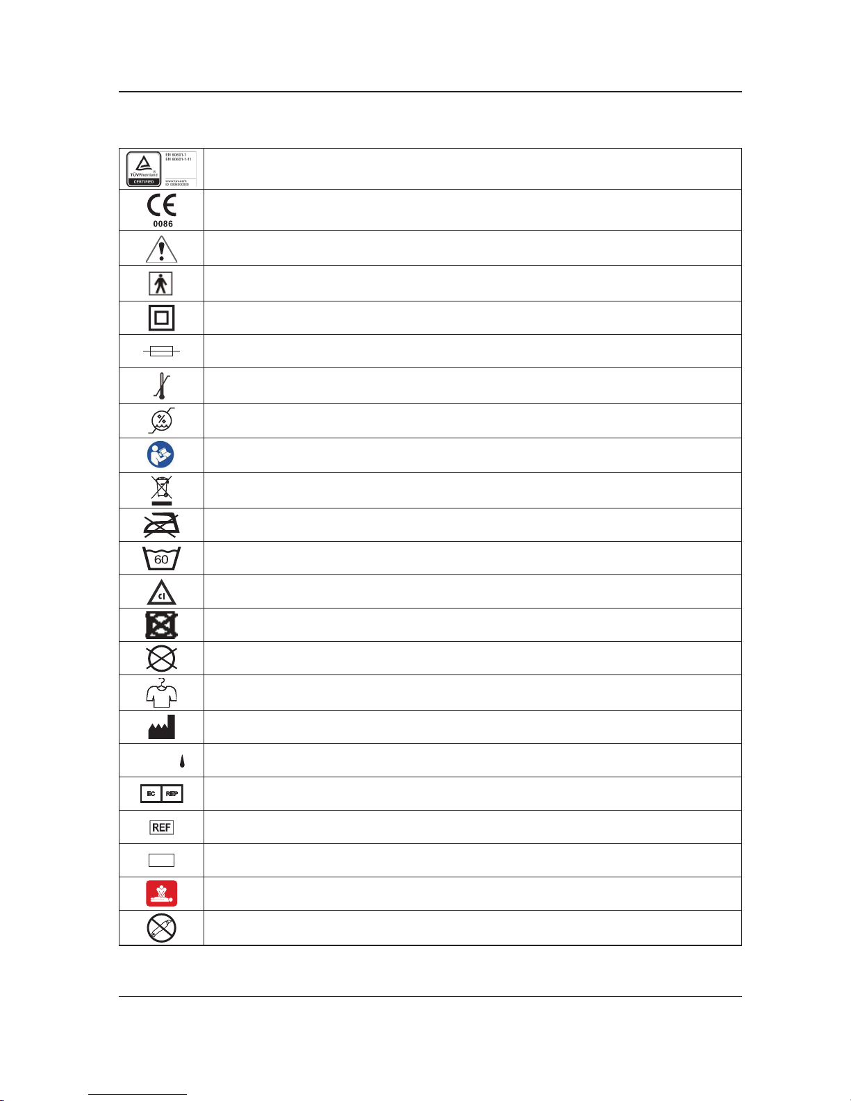
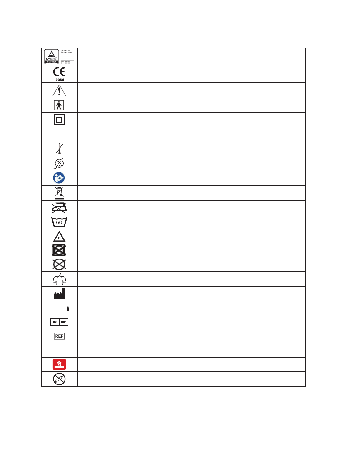
SYMBOLS
TUV marking
CE marking
Warning / Caution, consult accompanying documentation
Type BF equipment
Double Insulation
Fuse
Temperature Limitation, Operating: 10°C to 40°C, Storage: -15°C to 50°C
Humidity Limitation, 10% - 90%
Refer to instruction manual/ booklet
Disposal: Contact local distributor who will take the necessary steps according to your
national market.
Do Not Iron
Maximum washing temperature 60°C, normal process, only for top cover of mattress.
Chlorinated Bleach
Do Not Tumble Dry
Do Not Dry Clean
Allow to Completely Air Dry
Manufacturer
IP24
First Digit (Solids) Protected against touch by ngers (>12.5mm); Second Digit (Liquids)
Water splashing against the enclosure from any direction shall have no harmful effect.
Authorized representative in the European community
Catalogue Number (model)
SN
Serial Number
CPR
Do Not Open with Cutter
Page 5
www.stryker.com 836002-5210 V3.4 5
Return To Table of Contents
WARNING/CAUTION/NOTE DEFINITION
The words WARNING, CAUTION and NOTE carry special meanings and should be carefully reviewed.
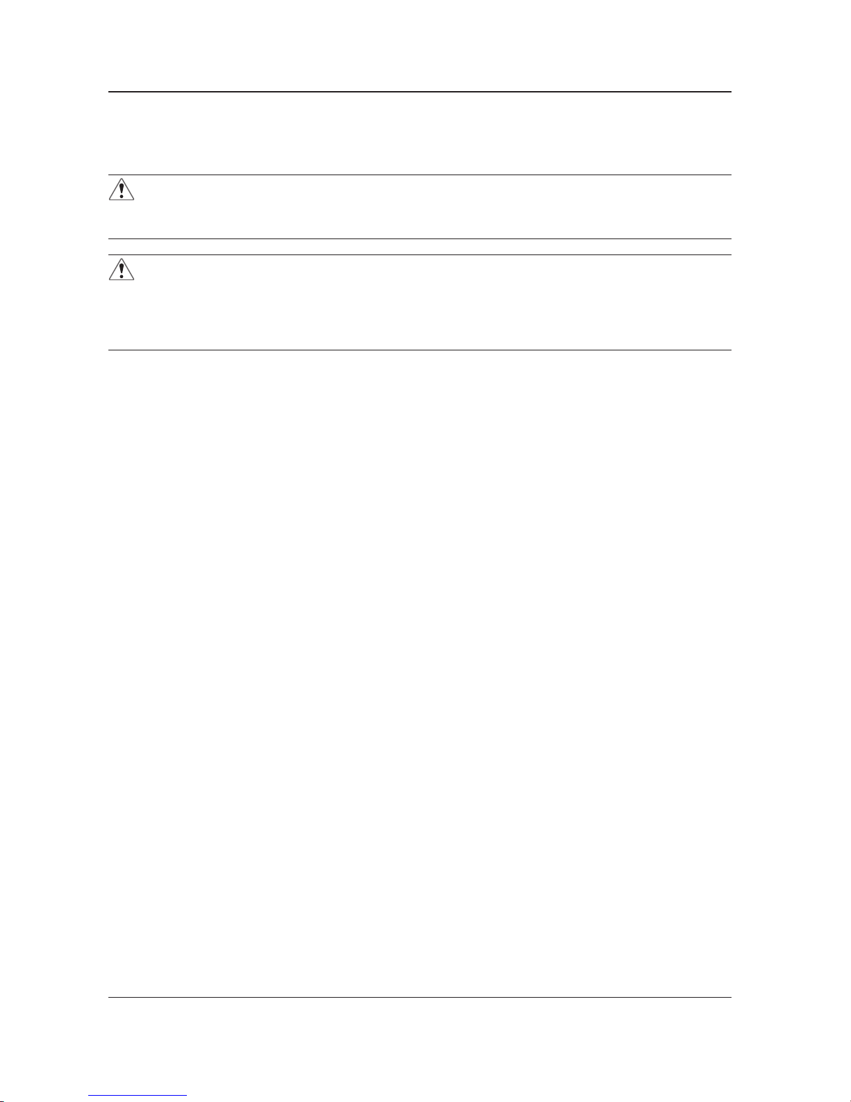
WARNING
Alert the reader about a situation which, if not avoided, could result in death or serious injury. It may also
describe potential serious adverse reactions and safety hazards.
CAUTION
Alert the reader of a potentially hazardous situation which, if not avoided, may result in minor or moderate
injury to the user or patient or damage to the equipment or other property. This includes special care necessary
for the safe and effective use of the device and the care necessary to avoid damage to a device that may
occur as a result of use or misuse.
NOTE
Provide special information to make maintenance easier or important instructions clearer.
Symbols and Denitions
Page 6
6 836002-5210 V3.4 www.stryker.com
Return To Table of Contents
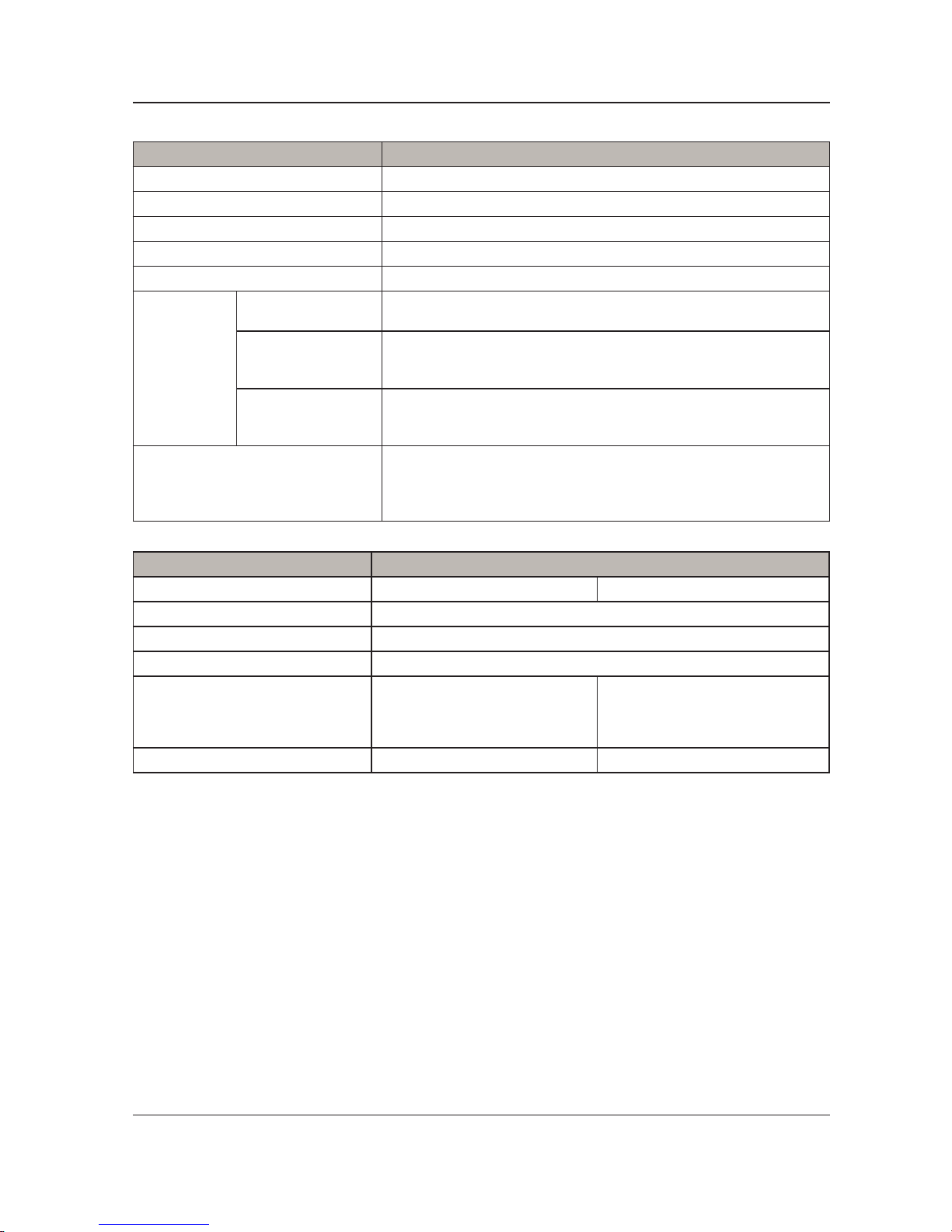
Item Specication
Power Supply AC 230V, 50Hz, 0.07A
Fuse Rating T1AL, 250V
Dimension (L x W x H) 29.5 x 14.5 x 19.2 cm / 11.5” x 5.7” x 7.6”
Weight 2.4 kg / 5.3 lb
Cycle Time 12 minutes
Environment
Atmospheric
Pressure
Operation: 70-106 hPa
Temperature
• Operation: 10°C to 40°C (50°F to 104°F)
• Storage: -15°C to 50°C (5°F to 122°F)
• Shipping: -15°C to 70°C (5°F to 158°F)
Humidity
• Operation: 10% to 90% non-condensing
• Storage: 10% to 90% non-condensing
• Shipping: 10% to 90% non-condensing
Classication
• Class II, Type BF, IP24
• Applied Part: Air Mattress
• Not suitable for use in the presence of a ammable anesthetic
mixture (No AP or APG protection)
Air Mattress Specication
Model EOLE DC 32” (80cm) EOLE DC 35” (90cm)
Model Number 2871
Flame Retardant Standards EN 597-1 and EN 597-2
Safe Working Load 200 kg / 441 lb
Dimension (L x W x H)
200 X 80 X 20 cm
78.74 X 32 X 7.84 inches
200 X 90 X 20 cm
78.74 X 35.43 X 7.84 inches
Weight 4.75 kg / 10.47 lb 5.45 kg / 12 lb
Technical Specication
Page 7

www.stryker.com 836002-5210 V3.4 7
Return To Table of Contents
This manual is designed to assist with the operation and maintenance of the EOLE DC Powered Support
Surface. Carefully read this manual thoroughly before using or beginning maintenance on the support
surface. To ensure safe operation of this equipment, it is recommended that methods and procedures are
established for educating and training staff.
CONTRAINDICATIONS
None known.
INTENDED USE OF PRODUCT
EOLE DC is a constant low pressure powered support surface intended to provide pressure redistribution to
aid in the prevention and treatment of pressure ulcers. The system consists of a control unit combined with
an alternating air cell mattress. The air cells redistribute the weight of the patient over the surface and aid in
the reduction of tissue interface pressure. It is recommended that the product be operated by personnel who
are qualied to perform general nursing procedures and have received adequate training in the prevention
and treatment of pressure ulcers.
This support surface is intended to be used with human patients in a general hospital, nursing home or
homecare environment and for patients at risk of developing pressure ulcers, as well as those who require
therapy for pre- existing pressure ulcers. The safe working load for EOLE DC is 200 kg/ 441 lb; the patient
must not exceed safe working load specied by the support surface, frame, and accessories. Patients shall
meet the minimum age requirement of 2 years old.
EOLE DC shall be used with a mattress cover at all times.
The support surface is not intended to be a sterile product nor is it intended to include a measuring function.
EXPECTED SERVICE LIFE
The products are intended to offer safe and reliable operation when in use or installed according to the
instructions provided by Stryker Medical. Stryker Medical recommends that the system be inspected and
serviced by authorized technicians if there are any signs of wear or concerns with device function and
indication on products. Otherwise, service and inspection of the devices generally should not be required.
The control unit thereof has an expected service life of 3 years and the mattress thereof has an expected
service life of 2 years.
PRODUCT DESCRIPTION
EOLE DC is powered support surface focusing on equalizing pressure and enhancing comfort.
Introduction
Page 8
8 836002-5210 V3.4 www.stryker.com
Return To Table of Contents
CONTACT INFORMATION
Contact Stryker Customer Service or Technical Support at: (800) 327-0770 or (269) 324-6500.
Stryker Medical
3800 E. Centre Avenue
Portage, MI 49002
USA
Please have the serial number (A) of your Stryker product available when calling Stryker Customer Service
or Technical Support. Include the serial number in all written communication.
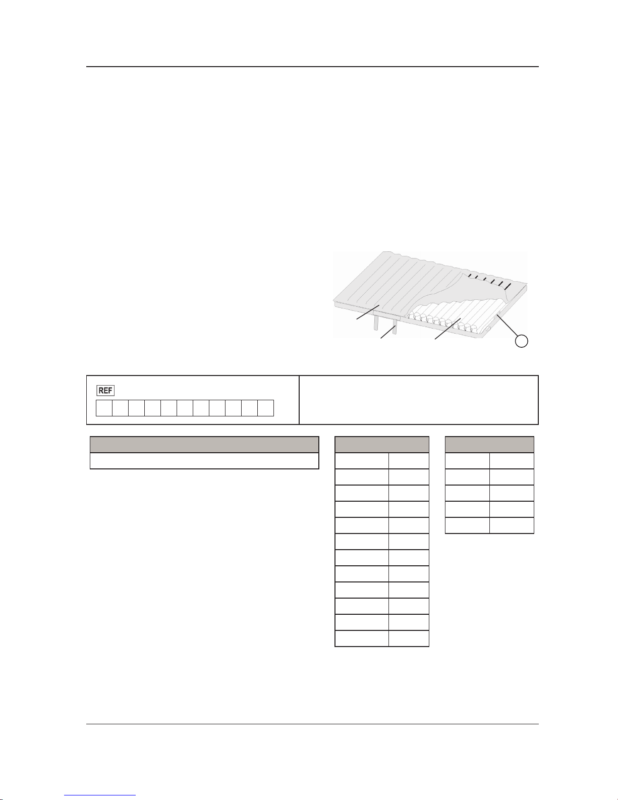
PRODUCT SERIAL NUMBER LOCATION/IDENTIFICATION
The serial number (A) is located at the mattress
cover near foot right corner of the mattress as shown
in Figure 1. To access the serial number, unzip the
cover about one foot.
▼
Figure 1
EOLE DC
Mattress
Air CellCPR
A
Format:
2871
M Y Y M M - S S S S S
• M = Mattress
• YY = Year
• MM = Month
• SSSSS = Sequence (Numeric)
Model Number Legend (X)
2871 EOLE DC
Month Legend (MM)
January 01
February 02
March 03
April 04
May 05
June 06
July 07
August 08
September 09
October 10
November 11
December 12
Year Legend (YY)
2014 14
2015 15
2016 16
2017 17
2018 18
Introduction
Page 9

www.stryker.com 836002-5210 V3.4 9
Return To Table of Contents
WARNING
• Check patient’s skin regularly. Consult physician if any redness or skin break occurs. Serious injury could
result if the patient’s skin condition is left untreated.
• Do not place the control unit in the patient’s bed, in contact with the patient, or under sheets or other
coverings. Doing so could cause serious injury or could affect control unit performance.
• Do not use in the presence of a ammable anesthetic mixture or with oxygen (O2) or nitrous oxide (N2O).
• Verify bed side rails are compatible with bed frame and existing mattress. A risk assessment must be
performed by a suitably qualied person, especially when side rails are prescribed, to ensure that the
bed meets the IEC 60601-2-52 bed standard.
• Use with appropriate top sheet and minimize layers of bedding between patient and mattress.
• Assess patient’s risk of entrapment according to protocols and monitor accordingly.
• Close supervision is necessary when this product is used on or near children. Electrical burns or choking
may result from a child swallowing a small part detached from the device.
• Use this product only for its intended use as described in this manual.
• Do not operate product if the power cord or plug has been damaged.
• Keep the power cord away from heated surfaces.
• Never block any air openings of this product or place it on soft surfaces, where openings may be blocked.
Keep the air opening free of lint, hair, and other similar particles.
• Do not modify this equipment without the authorization of the manufacturer.
• Mattress covers have passed skin sensitization and skin irritation tests. However, if you suspect that
the patient or caregiver you may have had or is having an allergic reaction, please consult a physician
immediately.
• The power cord to the Control Unit should be positioned to avoid a strangulation hazard and/or damage
to the cord. Careful consideration is required when routing the power cable. It is recommended that placing the cord under the bed frame and attaching it to an electrical outlet at the head of bed.
• Serious injury or death can result from the use (potential entrapment) or non-use (potential patient falls)
of side rails or other restraints. The safe use of the support surface is maximized when used in conjunction with side rails; there may be an increased risk of falls when side rails are not present. Local policies regarding the use of side rails should be taken into account. Whether and how to use side rails is a
decision that should be based on each patient’s individual needs and should be made by the physician,
operators, and responsible parties.
• When cleaning the support surface, ensure that no liquid is allowed to seep into the zipper area and
watershed cover barrier (underside); uids allowed to come in contact with the zipper may leak into the
support surface.
• Do not expose the mattress to excessive moisture. Personal injury or equipment damage could occur.
• The use of quaternaries containing glycol ethers and/or accelerated hydrogen peroxides may compro-
mise the cover integrity and legibility.
• Be aware of devices or equipment placed on the top of the support surface. Damage to the surface
may occur due to the weight of the equipment, heat generated by the equipment, or sharp edges on the
equipment.
• Do not put overlays or accessories inside the cover. Doing so may reduce pressure redistribution
performance.
• It is the responsibility of the caregiver team to evaluate the appropriate CPR protocol to be used with the
surface.
• If there is a possibility of electro-magnetic interference with mobile phones, please increase the distance
(3.3m/10.8 feet) between devices or turn off the mobile phone.
• Ensure the waterproof cap to the power switch is present and unbroken before use. Failure to do so could
increase risk of electric shock.
• Mattress contains metal snap buttons and delrin zippers and should not be exposed under X-rays entirely.
Always use X-ray cassette during portable X-ray procedure.
NOTE
The EOLE DC support surface must be used with a mattress cover at all times. The support surface cover
may interact with all external skin.
Summary of Safety Precautions
Page 10
10 836002-5210 V3.4 www.stryker.com
Return To Table of Contents
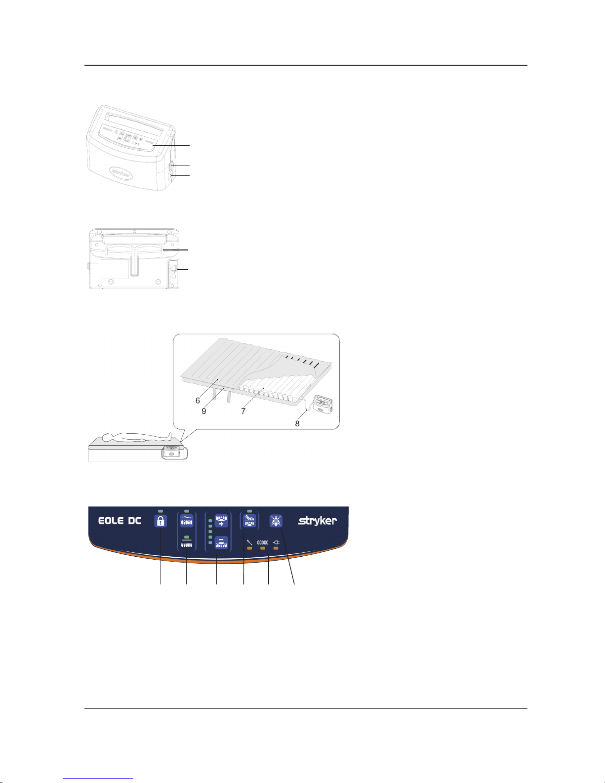
CONTROL UNIT FRONT
2
1
3
◄
Figure 2
1. Power Switch On/Off
2. Front Panel
3. Power Socket
CONTROL UNIT REAR
4
5
◄
Figure 3
4. Hanger
5. CPC Connector
◄
Figure 4
6. EOLE DC Mattress
7. Air Cell
8. Air Hose
9. CPR Strap
CONTROL PANEL
10 11 12 13 14 15
◄
Figure 5
10. Lock/Unlock
11. Mode Selection
12. Comfort Level
13. Maxrm/Seat mode
14. Alarm
15. Mute
Product Description
Page 11
www.stryker.com 836002-5210 V3.4 11
Return To Table of Contents
INSTALLING THE CONTROL UNIT
1. Place control unit on at surface or suspend control unit on end of bed using attached hooks. See Fig-
ure 2 and Figure 3. Remove the plug to disconnect the device. Do not position the equipment such that
it is difcult to operate the disconnecting device.
2. Position the mattress on bed frame.
3. Connect the hose assembly between the mattress air cell and the control unit. Connect the adaptor
from control unit onto the air valve.
4. Plug the power cord and Maxrm/Seat mode will be inated automatically. Note: The unit will take
approximately 40 minutes to inate the mattress. Nurse can adjust the comfort level or mode with the
patient on the initial stage.
5. After installation, make sure the ap is not folding upwards to avoid uid seeping through mattress
cover.
NOTE
Make sure the control unit is suitable for the local power voltage and frequency.
6. Position patient on the mattress.
WARNING
Deate before CPR or CPR could be ineffective.
To deate mattress for CPR:
When there is an emergency to perform CPR on the patient, quickly pull the CPR strap from the mattress
to release air. The quick connector on the pump unit can be disconnected for even faster deation. The
air cell will deate in approximately 15 seconds. Proceed with CPR procedures.
Resetting CPR:
After CPR, re-plug CPR and make sure the CPR plug is xed on the mattress.
Instructions
Page 12
12 836002-5210 V3.4 www.stryker.com
Return To Table of Contents
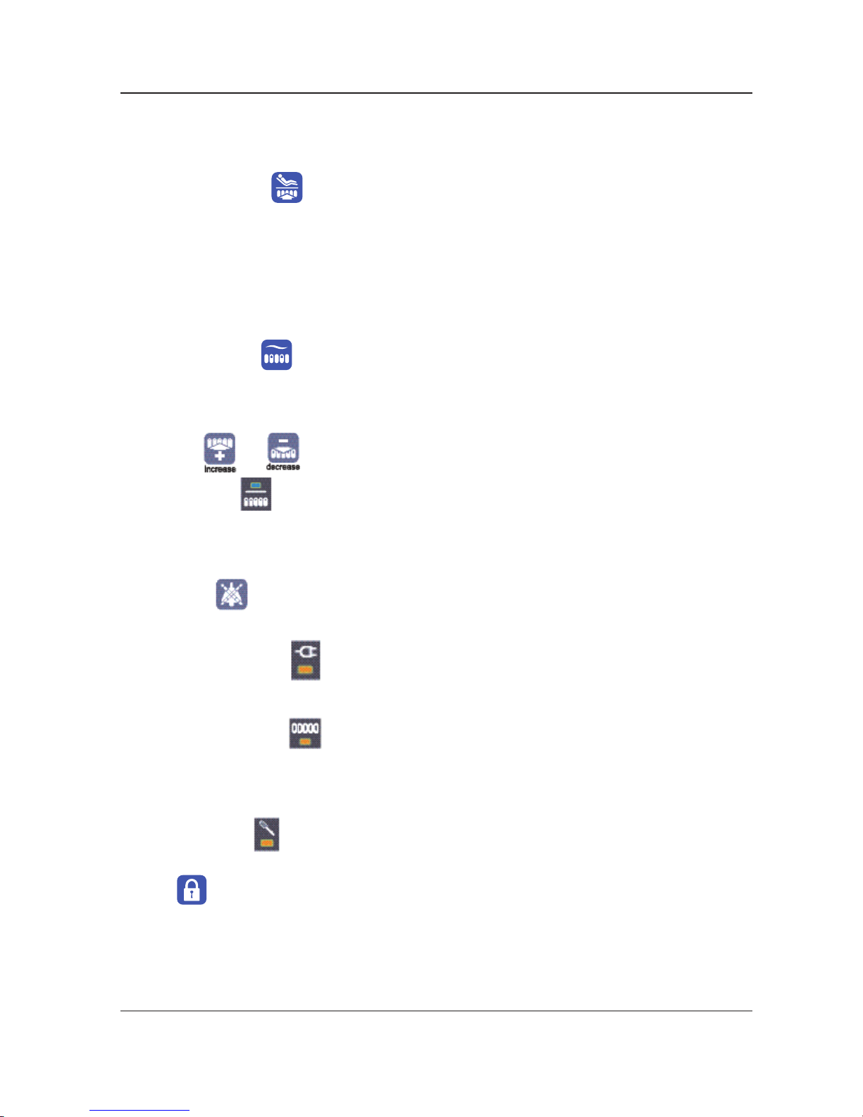
PRODUCT FUNCTIONS
THERAPY
1. Maxrm / Seat mode
When connected to the power for the rst time, the control unit automatically inates to maximum ination
and the indicator light of Maxrm/Seat comes on. This insures the control unit is able to reach its maximum
operating pressure. Once the maximum pressure level is reached, the pump will automatically switch
into alternating mode. User can also use this function as full mattress ination while ingress/egress the
patient for better support. Nurse or professional operator can adjust the comfort level manually at the
maxrm stage.
On the alternating or static mode, nurse can operate the maxrm button to implement the maxrm or
return to the former stage.
a. Alternate mode
In Alternate therapy mode, the mattress system will alternate every 12 minutes. User can select for
best comfort.
b. Comfort level:
Press
and to adjust the pressure level for the patient’s comfort.
c. Static mode
Press THERAPY button to suspend alternating function, if needed. The pressure inside of air cells will
be adjusted to the same softness. Press the THERAPY button again; it will switch back to alternating
mode. Under the static mode, cell pressure level will be lowered compare to the same pressure level
from alternating mode.
2. Alarm Mute
Press alarm mute to deactivate the alarm sound. If the problem continues, the alarm sounds again after
3 minutes.
a. Power Failure Alarm
During power failure situation, the Power Failure indicator will light on with sound. Upon power
restoration, press the power switch to disable the audible and visual alarm and LED.
b. Low Pressure Alarm
The audible low pressure alarm is not active during initial mattress ination. The audible alarm will be
active after approximately 50 minutes has elapsed from the time the unit has been turned on.
If there is a loss of mattress pressure with the unit ON and the alarm switch activated, an alarm will
sound and ash intermittently. In addition, the low pressure light will be illuminated.
c. Service Alarm
This feature will light during mechanical failure situation. User can notify the technician for repair.
3. Lock
Patient or caregiver can hold the lock button 3 seconds to activate or deactivate lock mode. In lock mode,
Patient or caregiver can press Maxrm/Seat button for maximum ination.
The panel of control unit will be lock automatically without any operation after 3 minutes.
Instructions
Page 13
www.stryker.com 836002-5210 V3.4 13
Return To Table of Contents
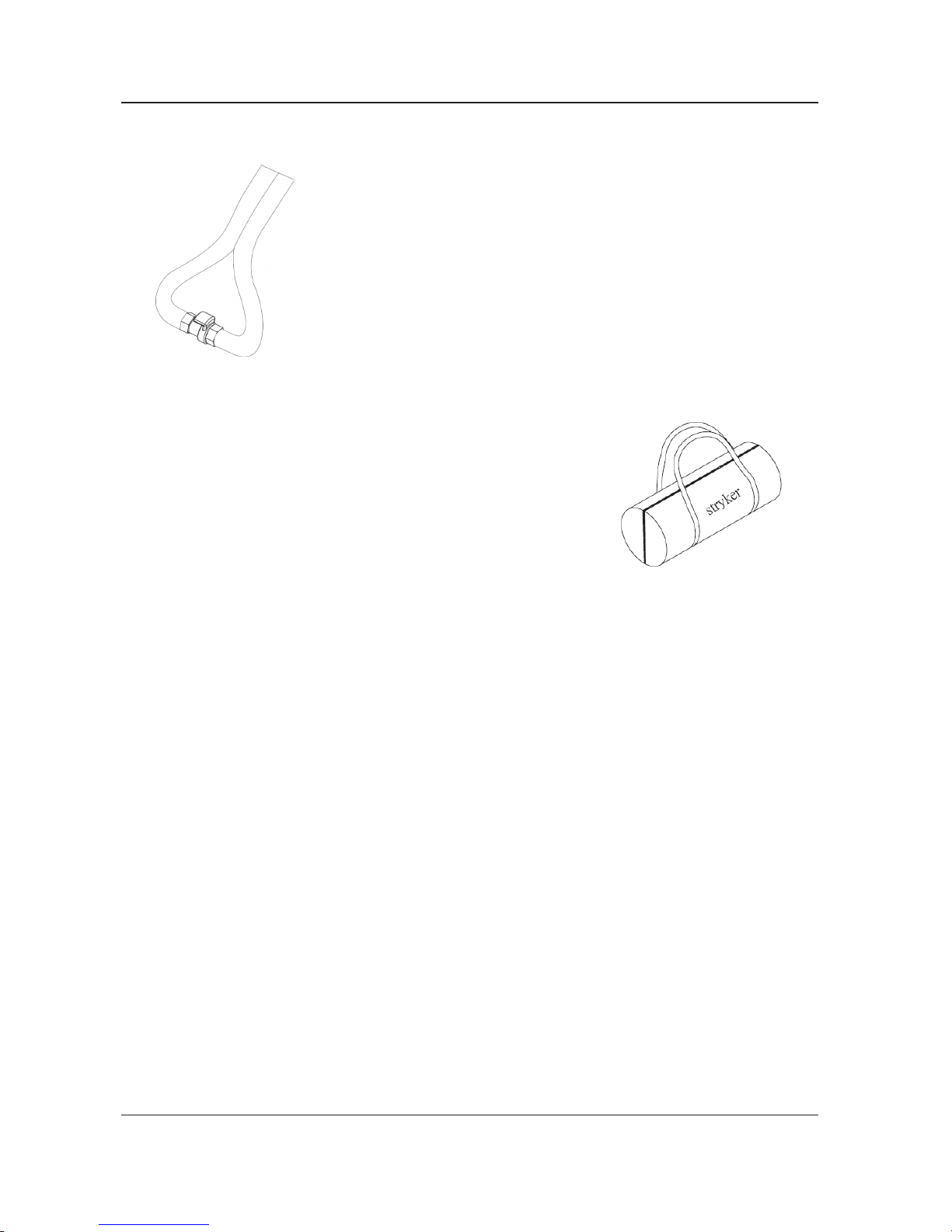
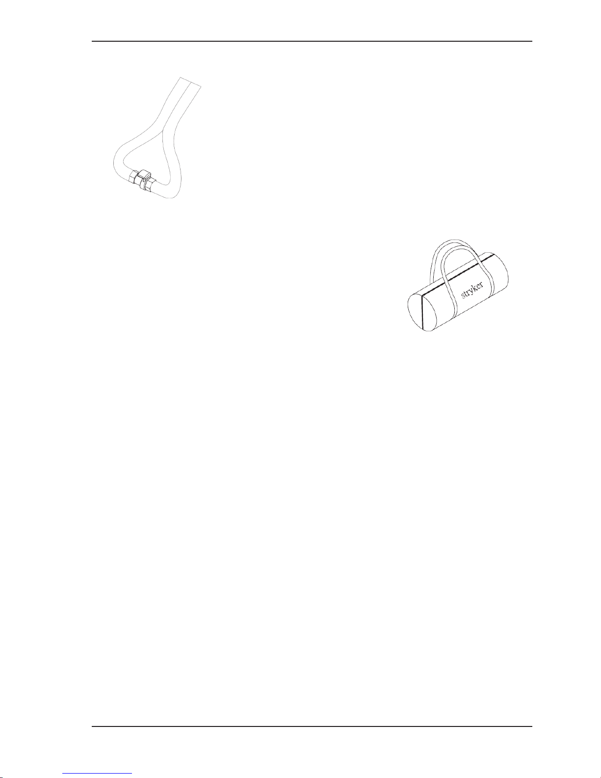
TRANSPORT MODE
In case of power failure or transport: Disconnect the CPC connector and
interconnect Male to Female part of the air hose connector to slow deation.
For transport purpose, interconnect Male to Female part of the air hose
connector. When a “click” is felt or heard, the connection is completed and
secured; then air from mattress is sealed off.
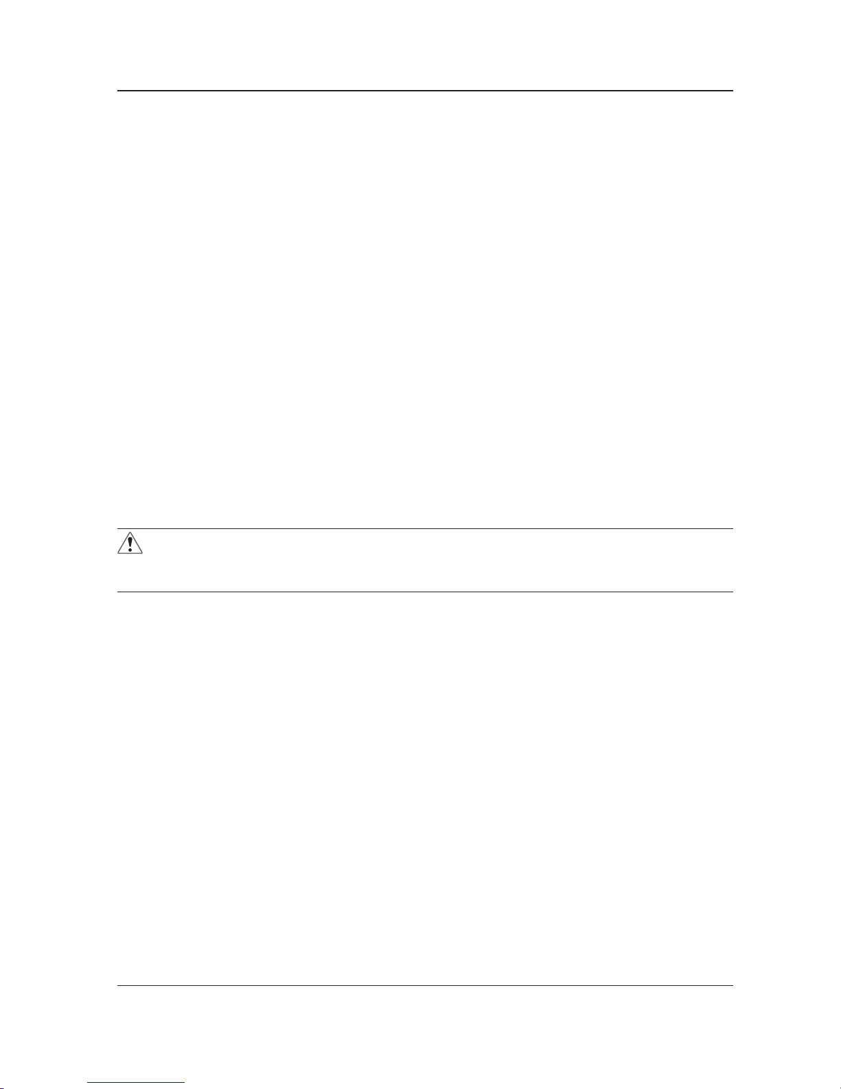
STORAGE
1. To quickly deate the mattress for storage, take off the CPR
strap and the CPC connectors. It will make the air release
quickly.
2. Lay the mattress out at and upsides down.
3. Fold in half and place the control unit inside.
4. Roll from the head end towards the foot end.
5. The power cord could be wrapped around the pump bumper on
the back of pump.
6. Place the whole system into the carrying bag.
Instructions
Page 14
14 836002-5210 V3.4 www.stryker.com
Return To Table of Contents
Cleaning and Disinfection
The control unit housing, tubing, and mattress should be cleaned between patients.
• To clean, use water and a clean cloth to wipe down the Control Unit, power cord, hoses, mattress top
cover, and bottom cover. Do not use abrasive cleaners on the mattress. Note: Blood and other body
uids must be thoroughly cleaned from all surfaces before applying disinfectants.
• Apply disinfectants to the external surfaces of the control unit, hoses and mattress top cover, and bottom cover by wiping. Stryker recommends a chlorine-based solution with a concentration less than or
equal to 1000 ppm or 70% alcohol twice a week.
• To wash the top cover of mattress by washing machine with normal process under the temperature
60°C in 45 minutes.
• It is not recommended to disinfect the internal parts of the mattress on a regular basis, but only as
needed for particular instance, the air cell could be wiped with a cloth and disinfectants as recommended above.
• Wipe down the mattress with a clean, dry cloth to remove any excess of disinfectant.
• If other detergent or other cleaning agent is used, choose one that will not have adverse chemical ef-
fects on the surface of the plastic case of the control unit, mattress cover and any other component of
the device.
• When cleaning or disinfecting the support surface, ensure that no liquid is allowed to seep into the zipper area and watershed cover barrier (underside); uids allowed to come in contact with the zipper may
leak into the support surface.
• Avoid dust and proximity to dusty areas.
• All components should be air dried thoroughly before use.
The waterproof cap of power switch should be on the power switch.
• Avoid using sharp tools on the waterproof cap over the power switch.
• Please reply to your distributor if the cap is broken or missed off.
WARNING
• Do not use phenolic based products for cleaning.
• Do no dry the mattress in direct sunlight.
Page 15
www.stryker.com 836002-5210 V3.4 15
Return To Table of Contents
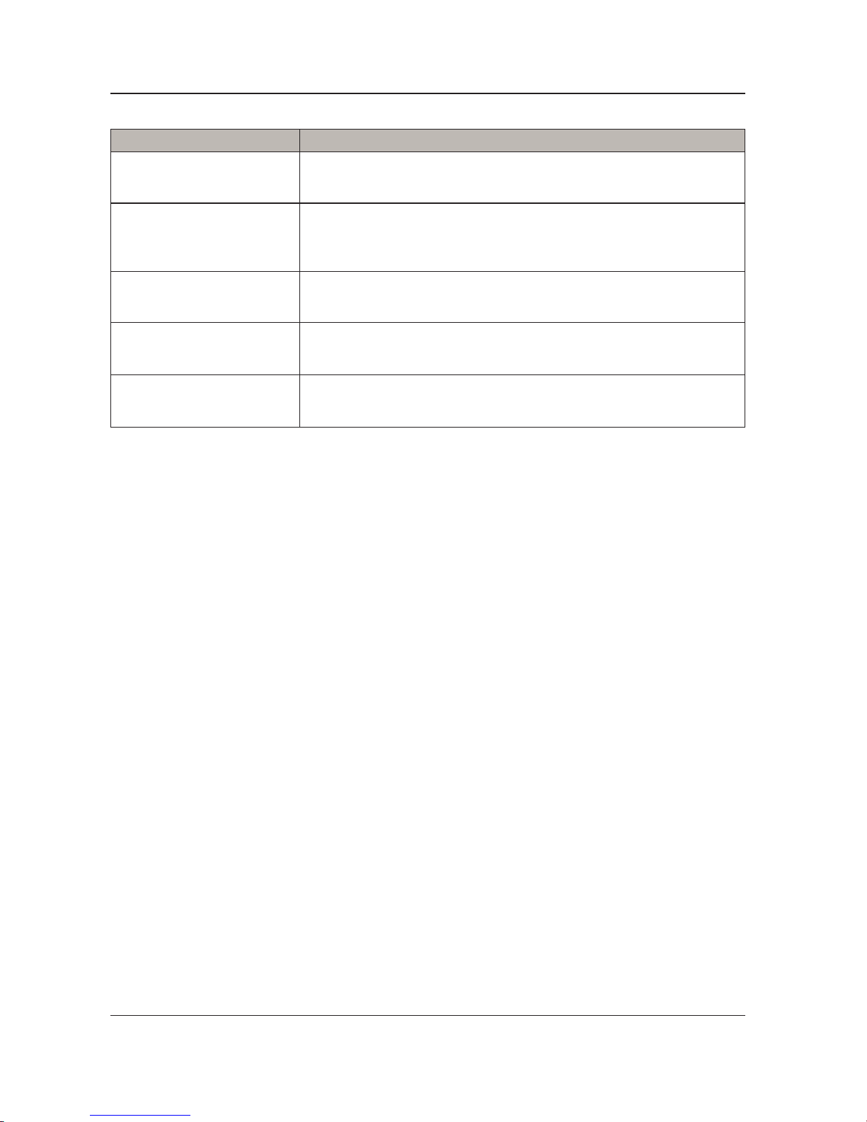
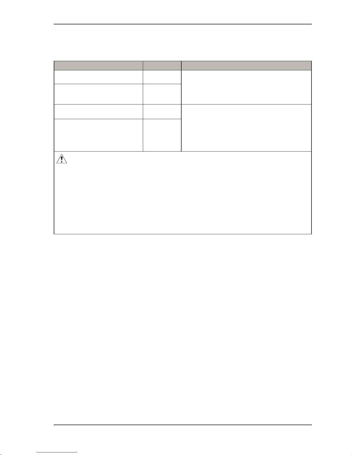
Troubleshooting
Problem Solution
Loss of power Check if the plug is connected to mains.
Low pressure alarm noises
1. Check if the CPR is sealed.
2. Check if the air cell is broken.
3. Check if the connection tube is tightly secured.
4. Check if there is any leakage on air cells.
Patient is bottoming out
Pressure setting might be inadequate for the patient. Adjust comfort range
1 to 2 levels higher and wait for a few minutes for best comfort.
Air Mattress is not secure
1. Check if all the snap buttons or straps of mattress are all securely
fastened.
2. Check if the mattress is xed to the bed frame by elastic straps.
Air cells fail to inate
Make sure the air hose is not kinked, cracked, or split. Verify that the power
switch is illuminated, signifying the control unit has power. Verify that the
air hoses are fully inserted with a positive connection.
Page 16

16 836002-5210 V3.4 www.stryker.com
Return To Table of Contents
TOP COVER REPLACEMENT
Tools Required: None
Procedure:
1. Disconnect the hose assembly between the mattress air cell and control unit.
2. Unzip the top cover.
3. Discard the old cover.
4. Place the new cover.
5. Carefully zip the cover.
6. Verify proper operation of the unit before returning it to service.
AIR CELL REPLACEMENT
Tools Required: None
Procedure:
1. Disconnect the hose assembly from the air valve of mattress.
2. Unzip 2-way zipper from either way to remove the top cover and remove the CPC tubes.
3. Remove and discard the old air cell.
4. Place the new air cell, connect the tubes and zip the cover to close.
5. Verify proper operation of the unit before returning it to service.
CONTROL UNIT REPLACEMENT
Tools Required: None
Procedure:
1. Disconnect the plug from mains power and hose.
2. Discard the old control unit.
3. Place the new control unit and connect the plug to mains power and hose.
4. Verify proper operation of the unit before returning it to service.
HOSE REPLACEMENT
Tools Required: None
Procedure:
1. Disconnect the hose from control unit and mattress.
2. Discard the old hose.
3. Connect the new hose to control unit and mattress.
4. Verify proper operation of the unit before returning it to service.
CPC TUBE REPLACEMENT
Tools Required: None
Procedure:
1. Disconnect the tube from control unit and mattress.
2. Discard the old tube.
3. Connect the new tube to control unit and mattress.
4. Verify proper operation of the unit before returning it to service.
FILTER REPLACEMENT
Tools Required: None
Procedure:
1. Discard the old lter.
2. Verify proper operation of the unit before returning it to service.
WARNING
Any replacement of non-authorized or wrong parts may cause the unpredictable risk rise. Please check the
replaced part is suitable for Stryker Medical’s EOLE DC Powered Support Surface, Model 2871.
Service Information
Page 17

www.stryker.com 836002-5210 V3.4 17
Return To Table of Contents
Preventative maintenance should be performed annually, at a minimum. A preventative maintenance
program should be established for all Stryker Medical equipment. Preventative maintenance may need to be
performed more frequently based on the usage level of the product.
CHECKLIST
_______ Cover zipper opens and closes properly and has no visible damage.
_______ No tears, rips, holes, cracks, or other openings in the mattress cover.
_______ Check labels for legibility, proper adherence, and integrity.
_______ Support surface cover straps and snaps are intact and are not damaged.
_______ Straps properly secure the support surface assembly to the crib.
_______ Components have not degraded or come apart.
_______ Check main power cord and do not plug if there is an abrasion or excessive wear.
_______ Check airow from the air hose.
_______ Check the air hose if there is kink or breaks
_______ Verify proper operation of the unit before returning it to service.
_______ Check the waterproof cap of power switch.
Preventive Maintenance
Product Serial Number:
Completed by: ___________________________________________ Date: _____________________
Page 18
18 836002-5210 V3.4 www.stryker.com
Return To Table of Contents
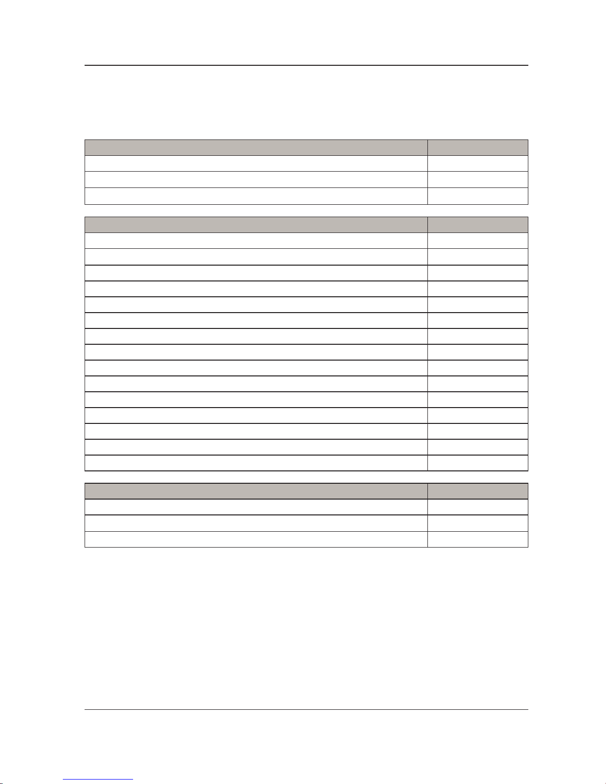
The parts and accessories listed on this page are currently available for purchase. Some of the parts identied
on the assembly drawing parts in this manual may not be individually available for purchase. Please call
Stryker Customer service USA at 1-800-327-0770 for availability and pricing.
Product Part Number
EOLE DC POWERED SUPPORT SURFACE 32” (80cm) 2871-000-002
EOLE DC POWERED SUPPORT SURFACE 35” (90cm) 2871-000-001
EOLE DC Control Unit 2871-001-000
Service Part Name Part Number
Manual, EOLE DC 2871-009-001
Mattress, Top Cover 32” (80cm) 2871-019-006
Single Air Cell, Orange PU 32” (80cm) 2871-019-007
Single Air Cell, Clear 32” (80cm) 2871-019-008
Mattress, Top Cover 35” (90cm) 2871-002-000
Single Air Cell, Orange PU 35” (90cm) 2871-004-001
Single Air Cell, Clear 35” (90cm) 2871-004-002
Air hose, PVC, EOLE DC 2871-004-003
Plug, Replacement, QTY 1 2871-004-004
Manifold 2871-004-005
Pump, Button Overlay, EOLE DC 2871-001-001
Pump, Fuse 2870-001-002
Tube, CPC 2870-001-003
Pump, Compressor 2870-001-004
Air Filter 2870-001-005
Accessory Part Number
Pump, UK Plug 2870-019-001
Transport Bag 2870-019-002
Pump, FR Plug 2870-019-003
Quick Reference Replacement Parts
Page 19

www.stryker.com 836002-5210 V3.4 19
Return To Table of Contents
Appendix A: EMC Information
GUIDANCE AND MANUFACTURER’S DECLARATION- ELECTROMAGNETIC EMISSIONS:
This device is intended for use in the electromagnetic environment specied below. The user of this device
should make sure it is used in such an environment.
Emissions Test Compliance Electromagnetic Environment-Guidance
RF emissions
CISPR 11
Group1
The device uses RF energy only for its internal
function. Therefore, its RF emissions are very
low and are not likely to cause any interference in
nearby electronic equipment
RF emissions
CISPR 11
Class B
Harmonic emissions
IEC61000-3-2
Class A
The device is suitable for use in all establishments,
including domestic establishments and those
directly connected to the public low-voltage power
supply network
Voltage uctuations / Flicker
emissions
IEC61000-3-3
Complies
WARNING
1. The device should not be used adjacent to or stacked with other equipment. If adjacent or stacked use
is necessary, the device should be observed to verify normal operation in the conguration in which it will
be used.
2.Use of accessories, transducers and cables other than those specied or provided by the
manufacturer of this equipment could result in increased electromagnetic emissions or decreased
electromagnetic immunity of this equipment and result in improper operation.
3. Portable RF communications equipment (including peripherals such as antenna cables and external
antennas) should be used no closer than 30 cm (12 inches) to any part of the Pump, including cables
specied by the manufacturer. Otherwise, degradation of the performance of this equipment could result.
Page 20
20 836002-5210 V3.4 www.stryker.com
Return To Table of Contents
Appendix A: EMC Information
GUIDANCE AND MANUFACTURER’S DECLARATION- ELECTROMAGNETIC IMMUNITY:
This device is intended for use in the electromagnetic environment specied below. The user of this device
should make sure it is used in such an environment.
Basic EMC
standard
Immunity Test Levels Compliance
Levels
Electromagnetic
Environment-Guidance
HOME HEALTHCARE
ENVIRONMENT
Electrostatic
Discharge (ESD)
IEC61000-4-2
±8kV contact
±15kV air
±8kV contact
±15kV air
Floors should be wood, concrete or
ceramic tile. If oors are covered
with synthetic material, the relative
humidity should be at least 30 %.
Electrical fast
transient/ burst
IEC61000-4-4
±2kV for power supply line
±1kV for input/output line
±2kV for power
supply line
±1kV for input/
output line
Mains power quality should be that
of a typical commercial or hospital
environment
Surge
IEC61000-4-5
± 1 kV line(s) to
line(s)
± 2 kV line(s) to earth
± 1 kV line(s) to
line(s)
Mains power quality should be that
of a typical commercial or hospital
environment.
Voltage dips,
short interruptions
and voltage
variations on
power supply
input lines
IEC61000-4-11
Voltage Dips:
i) 100% reduction for 0.5
period,
ii) 100% reduction for 1
period,
iii) 30% reduction for 25/30
period,
Voltage Interruptions:
100% reduction for 250/300
period
230V (UT)
(1)
Voltage Dips:
i) 100%
reduction for 0.5
period,
ii) 100%
reduction for 1
period,
iii) 30%
reduction for
25/30 period,
Voltage
Interruptions:
100% reduction
for 250/300
period
Mains power quality should be that
of a typical commercial or hospital
environment. If the user of this
device requires continued operation
during power mains interruptions,
it is recommended that the device
be powered from an uninterruptible
power supply or a battery.
Power frequency
(50/60Hz)
magnetic eld
IEC61000-4-8
30 A/m 30 A/m Power frequency magnetic elds
should be at levels characteristic
of a typical location in a typical
commercial or hospital environment.
Conducted RF
IEC 61000-4-6
3 Vrms
0,15 MHz – 80 MHz
6 Vrms in ISM and amateur
radio bands between
0,15 MHz and 80 MHz
80 % AM at 1 kHz
(4)
6Vrms Portable and mobile RF
communications equipment should
be used no closer to any part of this
device, including cables, than the
recommended separation distance
calculated from the equation
applicable to the frequency of the
transmitter.
Page 21
www.stryker.com 836002-5210 V3.4 21
Return To Table of Contents
Appendix A: EMC Information
Radiated RF EM
Fields
IEC61000-4-3
10 V/m 80 MHz to 2,7 GHz
80 % AM at 1 kHz
385-6000 MHz, 9-28V/m,
80% AM(1kHz) pulse mode
and other modulation
10V/m
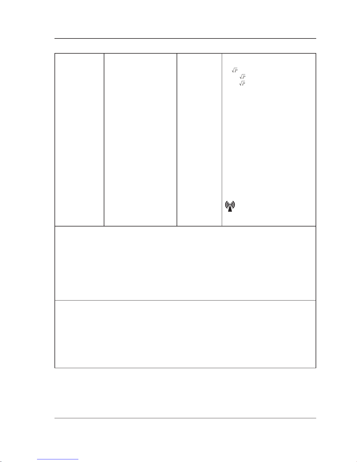
Recommended separation distance
d= 150kHz to 80MHz
d=0.6 80MHz to 800MHz
d=1.2 800 MHz to 2.7G Hz
Where P is the maximum output
power rating of the transmitter
in watts (W) according to the
transmitter manufacturer and d
is the recommended separation
distance in meters (m).
b
Field strengths from xed RF
transmitters, as determined by
an electromagnetic site survey ,a
should be less than the compliance
level in each frequency ranged.
Interference may occur in the
vicinity of equipment marked with
the following symbol:
NOTE 1: UT is the a.c. mains voltage prior to the application of the test level
NOTE 2: At 80 MHz and 800 MHz, the higher frequency range applies.
NOTE 3: These guidelines may not apply in all situations. Electromagnetic propagation is affected by
absorption and reection from structures, objects and people
NOTE 4:The ISM (industrial, scientic and medical) bands between 0.15 MHz and 80 MHz are 6.765 MHz
to 6.795 MHz; 13.553 MHz to 13.567 MHz; 26.957 MHz to 27.283 MHz; and 40.66 MHz to 40.70 MHz.
The amateur radio bandsbetween 0.15 MHz and 80 MHz are 1.8 MHz to 2.0 MHz, 3.5 MHz to 4.0 MHz,
5.3 MHz to 5.4 MHz, 7 MHz to 7.3 MHz,10.1 MHz to 10.15 MHz, 14 MHz to 14.2 MHz, 18.07 MHz to 18.17
MHz, 21.0 MHz to 21.4 MHz, 24.89 MHz to 24.99MHz, 28.0 MHz to 29.7 MHz and 50.0 MHz to 54.0
MHz.
a)Field strengths from xed transmitters, such as base stations for radio (cellular/cordless) telephones
and land
mobile radios, amateur radio, AM and FM radio broadcast and TV broadcast cannot be predicted
theoretically with accuracy. To assess the electromagnetic environment due to xed RF transmitters, an
electromagnetic site survey should be considered. If the measured eld strength in the location in which
the device is used exceeds the applicable RF compliance level above, the device should be observed to
verify normal operation. If abnormal performance is observed, additional measures may be necessary,
such as reorienting or relocating the device.
b) Over the frequency range 150 kHz to 80 MHz, eld strengths should be less than 10 V/m.
Page 22

22 836002-5210 V3.4 www.stryker.com
Return To Table of Contents
LIMITED WARRANTY
Stryker Medical Division, a division of Stryker Corporation, warrants to the original purchaser EOLE DC
Powered Support Surface, Model 2871 to be free from defects in material and workmanship for a period
of two (2) years for the support surface assembly and the control unit after date of delivery under normal
use*. Stryker’s obligation under this warranty is expressly limited to supplying replacement parts and labor
for, or replacing, at this option, any product which is, in the sole discretion of Stryker, found to be effective. If
requested by Stryker, products or parts for which a warranty claim is made shall be returned to the factory.
Any improper use or any alteration or repair by others in such manner as in Stryker’s judgment affects
the product materially and adversely shall void this warranty. Any repair of Stryker products using parts
not provided or authorized by Stryker shall void this warranty. No employee or representative of Stryker is
authorized to change this warranty in any way.
CONDITIONS AND LIMITATIONS
Stryker Medical’s EOLE DC Powered Support Surface, Model 2871 is designed for an expected service life
as listed below under normal use conditions, and with appropriate periodic maintenance as described in the
operations/maintenance manual for each device.
This statement constitutes Stryker’s entire warranty with respect to the aforesaid equipment. Stryker makes
no other warranty or representation, either expressed or implied, except as set forth herein. There
is no warranty of merchantability and there are no warranties of tness for any particular purpose.
in no event shall Stryker be liable here under for incidental or consequential damages arising from
or in any manner related to sales or use of any such equipment. This warranty does not extend to,
nor cover:
• Normal wear and tear; or
• Damage or product failure due to causes beyond Stryker’s control such as, but not limited to abuse,
theft, re, ood, wind , lightning, freezing, clogging of mattress pores due to tobacco smoke, unusual
atmosphere conditions, material degradation due to exposure to moisture; or
• Damage to support surface or support surface handles through the use of the support surface for patient transfer or transport.
* Normal use is dened as normal hospital or facility usage. Damages arising from abnormal use such as
those caused by needle punctures, burns, chemicals, negligent use or improper care or improper cleaning or
staining resulting from it are exempt from warranty coverage.
TO OBTAIN PARTS AND SERVICE
Stryker products are supported by a nationwide network of dedicated Stryker Field Service Representatives.
These representatives are factory trained, available locally, and carry a substantial spare parts inventory
to minimize repair time. Simply call your local representative or call Stryker Customer Service USA at
1-800-327-0770.
RETURN AUTHORIZATION
Merchandise cannot be returned without approval from the Stryker Customer Service Department. An
authorization number will be provided which must be printed on the returned merchandise. Stryker reserves
the right to charge shipping and restocking fees on return merchandise. Special, modied, or discontinued
items not subject to return.
DAMAGED MERCHANDISE
ICC Regulations require that claims for damaged merchandise must be made with the carrier within fteen
(15) days of receipt of merchandise. Do not accept damaged shipments unless such damage is noted
on the delivery receipt at the time of receipt. Upon prompt notication, Stryker will le a freight claim with
the appropriate carrier for damages incurred. Claim will be limited in amount to the actual replacement cost.
In the event that this information is not received by Stryker within the fteen (15) days period following the
delivery of the merchandise, or the damage was not noted on the delivery receipt at the time of receipt, the
customer will be responsible for payment of the original invoice in full. Claims for any short shipment must be
made within thirty (30) days of invoice.
INTERNATIONAL WARRANTY CLAUSE
This warranty reects U.S. domestic policy. Warranty outside the U.S. may vary by country. Please contact
your local Stryker Medical representative for extra information.
Warranty
Page 23

www.stryker.com 836002-5210 V3.4 23
Return To Table of Contents
Page 24

Stryker Medical
3800 E. Centre Avenue
Portage, Michigan 49002
USA
www.stryker.com
Stryker European Operations B.V.
Herikerbergweg 110
Amsterdam
1101 CM
Netherlands
Page 25
2017/12 836002-5210 V3.4 www.stryker.com
Surface de soutien alimentée en DC EOLE
2871
Guide d'utilisation/de maintenance
Page 26

Page 27

www.stryker.com 836002-5210 V3.4 3
Sommaire
Symboles et dénitions ................................................................ 4
Symboles ........................................................................ 4
Avertissement/Attention/Remarque : Dénition........................................... 5
Spécications techniques............................................................... 6
Introduction.......................................................................... 7
Contre-indications ................................................................. 7
Utilisation prévue du produit ......................................................... 7
Durée de vie prévue................................................................ 7
Description du produit .............................................................. 7
Informations de contact ............................................................. 8
Emplacement du numéro de série du produit/Identication ................................. 8
Récapitulatif des précautions de sécurité .................................................. 9
Description du produit ................................................................ 10
Panneau avant de l'unité de commande ............................................... 10
Panneau arrière de l'unité de commande .............................................. 10
Panneau de commande............................................................ 10
Instructions ..........................................................................11
Installation de l'unité de commande....................................................11
Fonctionnalités du produit .......................................................... 12
Mode de transport . . . . . . . . . . . . . . . . . . . . . . . . . . . . . . . . . . . . . . . . . . . . . . . . . . . . . . . . . . . . . . . . 13
Stockage ....................................................................... 13
Nettoyage et désinfection.............................................................. 14
Dépannage......................................................................... 15
Informations de maintenance ........................................................... 16
Remplacement du protège-matelas supérieur .......................................... 16
Remplacement de la cellule d'air ..................................................... 16
Remplacement de l'unité de commande ............................................... 16
Remplacement du tuyau ........................................................... 16
Remplacement du tube CPC ........................................................ 16
Remplacement du ltre ............................................................ 16
Maintenance préventive ............................................................... 17
Liste de contrôle.................................................................. 17
Annexe A : Information relative à la compatibilité électromagnétique . . . . . . . . . . . . . . . . . . . . . . . . . . . . 19
Directive et déclaration du fabricant - Émissions électromagnétiques:........................ 19
Directive et déclaration du fabricant - Immunité électromagnétique:.......................... 20
Garantie ........................................................................... 22
Limite de garantie ................................................................ 22
Méthode d'obtention de pièces de rechange et de prestations de maintenance ................ 22
Autorisation de retour.............................................................. 22
Marchandise endommagée ......................................................... 22
Clause de garantie internationale .................................................... 22
Page 28
4 836002-5210 V3.4 www.stryker.com
Retour au Sommaire
Symboles et dénitions
SYMBOLES
Marquage TÜV
Marquage CE
Avertissement/Attention : consulter la documentation fournie
Équipement BF
Isolation double
Fusible
Limites de température - De fonctionnement : 10 °C à 40 °C - De stockage : -15 °C à 50 °C
Limites d'humidité : 10 % - 90 %
Voir le manuel d'instructions
Mise au rebut : contacter le distributeur local, qui prendra les mesures nécessaires, en
fonction du pays concerné.
Ne pas repasser
Température de lavage maximale : 60 °C, lavage normal (uniquement du protège-matelas).
Blanchiment chloré
Ne pas utiliser de sèche-linge
Ne pas nettoyer à sec
Laisser l'appareil sécher totalement à l'air
Fabricant
IP24
Premier chiffre (Solides) P ro t ec ti o n co nt r e l e c on t a ct av e c l es doi g ts (>12 , 5 m m) ; Deuxième
chiffre (Liquides) Les éclaboussures d'eau sur le boîtier sont sans conséquence.
Représentant agréé au sein de la Communauté européenne
Numéro catalogue (modèle)
SN
Numéro de série
CPR
Ne pas ouvrir avec un cutter
Page 29
www.stryker.com 836002-5210 V3.4 5
Retour au Sommaire
AVERTISSEMENT/ATTENTION/REMARQUE : DÉFINITION
Les termes AVERTISSEMENT, ATTENTION et REMARQUE ont des signications spéciques et une
attention particulière doit y être apportée.
AVERTISSEMENT
Alerter le lecteur au sujet d'une situation qui, s'il n'était pas possible de l'éviter, risquerait d'entraîner des
blessures graves, voire mortelles. Description de réactions indésirables potentielles et de risques de sécurité
graves.
ATTENTION
Alerter le lecteur quant aux situations potentiellement dangereuses risquant d'entraîner des blessures légères
à modérées de l'utilisateur ou du patient, ou encore d'endommager l'équipement ou d'autres dispositifs. Une
attention particulière doit être apportée an d'utiliser l'équipement de façon sécurisée et efcace, et d'éviter
d'endommager l'équipement suite à une mauvaise utilisation de ce dernier.
REMARQUE
Fournir des informations spéciques visant à faciliter la maintenance ou la compréhension des instructions
importantes.
Symboles et dénitions
Page 30
6 836002-5210 V3.4 www.stryker.com
Retour au Sommaire
Article Spécication
Alimentation CA 230 V, 50 Hz, 0,07 A
Calibre des fusibles T1AL, 250 V
Dimensions (l x L x H) 29,5 x 14,5 x 19,2 cm
Poids 2,4 kg
Durée d'un cycle 12 minutes
Environnement
Pression
atmosphérique
De fonctionnement : 70-106 hPa
Température
• De fonctionnement : 10 °C à 40 °C
• De stockage : -15 °C à 50 °C
• D'expédition : -15 °C à 70 °C
Humidité
• De fonctionnement : 10 % à 90 %, sans condensation
• De stockage : 10 % à 90 %, sans condensation
• D'expédition : 10 % à 90 %, sans condensation
Classication
• Classe II, Type BF, IP24
• Pièce : Matelas à air
• Non adapté à une utilisation en présence d’un mélange de
produits anesthésiques inammables (absence de protection
AP ou APG)
Matelas à air Spécication
Modèle EOLE DC 32” (80cm) EOLE DC 35” (90cm)
Référence modèle 2871
Normes applicables aux produits
ignifuges
EN 597-1 et EN 597-2
Charge maximale 200 kg
Dimensions (l x L x H) 200 X 80 X 20 cm 200 X 90 X 20 cm
Poids 4,75 kg 5,45 kg
Spécications techniques
Page 31

www.stryker.com 836002-5210 V3.4 7
Retour au Sommaire
Ce manuel a pour objectif de faciliter l'utilisation et la maintenance du produit Surface de soutien alimentée en
DC EOLE. Lisez-le attentivement avant d'utiliser l'équipement ou d'effectuer des opérations de maintenance.
Pour garantir un fonctionnement de l'appareil dans de bonnes conditions de sécurité, il est recommandé de
mettre en œuvre des méthodes et des procédures visant à former le personnel.
CONTRE-INDICATIONS
Aucune connue.
UTILISATION PRÉVUE DU PRODUIT
EOLE DC est une surface de soutien à alimentation continue basse pression permettant de prévenir et
de traiter les escarres. Ce système se compose d'une unité de commande et d'un matelas à cellules d'air
à pression alternée. Les cellules d'air redistribuent le poids du patient sur la totalité de la surface, permettant
ainsi de réduire la pression sur les tissus. L'utilisation du produit doit être conée à un personnel qualié,
capable d'exécuter des soins inrmiers classiques, et formé en matière de prévention et de traitement des
escarres.
Ce dispositif est destiné aux patients hospitalisés, ou se trouvant dans des environnements de maisons
de soins inrmiers ou de soins à domicile, ainsi qu'aux patients risquant de développer des escarres ou
nécessitant un traitement pour des escarres préexistants. La charge maximale d'EOLE DC est de 200 kg ;
le patient ne doit pas dépasser le poids spécié pour la surface, le cadre et les accessoires. Les patients
doivent être âgés au minimum de 2 ans.
EOLE DC doit en permanence être utilisé avec un protège-matelas.
Il ne s'agit ni d'un appareil stérile, ni d'un dispositif de mesure.
DURÉE DE VIE PRÉVUE
Ces produits offrent un fonctionnement able et sécurisé lorsqu'ils sont utilisés ou installés conformément
aux instructions fournies par Stryker Medical. Stryker Medical recommande de faire inspecter et entretenir
le système par des techniciens agréés, en cas de signes d'usure ou de problèmes de fonctionnement ou
de signalisation sur le produit. Dans tous les autres cas, ces opérations ne sont pas nécessaires. L'unité de
commande a une durée de vie prévue de 3 ans, et le matelas de 2 ans.
DESCRIPTION DU PRODUIT
EOLE DC est une surface à air motorisée permettant d'égaliser la pression exercée et de maximiser le
confort des patients.
Introduction
Page 32

8 836002-5210 V3.4 www.stryker.com
Retour au Sommaire
INFORMATIONS DE CONTACT
Contactez le service d'assistance clientèle ou le support technique de Stryker, au numéro suivant :
(800) 327-0770 ou (269) 324-6500.
Stryker Medical
3800 E. Centre Avenue
Portage, Michigan 49002
ÉTATS - U NIS
Munissez-vous du numéro de série (A) de votre produit Stryker lorsque vous appelez le service d'assistance
clientèle ou le service de support technique de Stryker. De la même façon, mentionnez le numéro de série
du produit dans tous vos envois de courriers.
EMPLACEMENT DU NUMÉRO DE SÉRIE DU PRODUIT/IDENTIFICATION
Le numéro de série (A) se trouve sur le protègematelas, dans l'angle inférieur droit, comme l'illustre
la Figure 1. Pour accéder à ce numéro de série,
ouvrir légèrement (de 30 cm) la fermeture éclair du
protège-matelas.
▼
Figure 1
Matelas
EOLE DC
Cellule d’airCPR
A
Format :
2871
M A A M M - S S S S S
• M = Matelas
• AA = Année
• MM = Mois
• SSSSS = Séquence (Numérique)
Légende Référence modèle (X)
2871 EOLE DC
Légende Mois (MM)
Janvier 01
Février 02
Mars 03
Avril 04
Mai 05
Juin 06
Juillet 07
Août 08
Septembre 09
Octobre 10
Novembre 11
Décembre 12
Légende Année
(AA)
2014 14
2015 15
2016 16
2017 17
2018 18
Introduction
Page 33

www.stryker.com 836002-5210 V3.4 9
Retour au Sommaire
AVERTISSEMENT
• Vérier régulièrement la peau du patient. En cas de rougeur ou d'altération de la peau, consulter un médecin.
L'absence de traitement de ces altérations de la peau risquerait d'entraîner de graves blessures pour le patient.
• Ne pas placer l'unité de commande dans le lit du patient, au contact avec ce dernier ou sous les draps ou
couvertures. En effet, cela risquerait d'entraîner de graves blessures ou de diminuer les performances
de l'unité de commande.
• Ne pas utiliser en présence d'un mélange anesthésiant inammable ou comportant de l'oxygène (O2) ou
de l'oxyde d'azote (N2O).
• Vérier que les rails latéraux du lit sont compatibles avec le cadre du lit et avec le matelas existant. Une
évaluation des risques doit être effectuée par une personne habilitée, et tout particulièrement lorsque des rails
latéraux sont prescrits, an de garantir que le lit soit conforme aux dispositions de la norme IEC 60601-2-52.
• Utiliser avec un drap approprié et minimiser les couches entre le patient et le matelas.
• Évaluer le risque de piégeage du patient, conformément aux protocoles en vigueur, et effectuer les
vérications correspondantes.
• Une surveillance étroite est requise lors de l'utilisation du produit avec des enfants ou à proximité
d'enfants. Des brûlures électriques ou une suffocation peuvent se produire si un enfant avale une petite
pièce s'étant détachée de l'appareil.
• N'utiliser ce produit que pour les utilisations prévues, décrites dans le présent manuel.
• Ne pas utiliser ce produit si le cordon ou la prise d'alimentation a été endommagé(e).
• Maintenir le cordon d'alimentation à distance des surfaces chauffées.
• Ne jamais bloquer les ouvertures d'air du produit, ne jamais le placer sur des surfaces risquant d'obturer les
ouvertures. Veiller à ce que les ouvertures ne soient pas obturées par des particules (peluches, cheveux ou autres).
• Ne pas apporter de modication à cet équipement sans l'autorisation du fabricant.
• Les protège-matelas ont été soumis à des tests de sensibilisation et d'irritation de la peau. Toutefois,
si vous pensez que le patient ou le soignant est susceptible d'avoir une réaction allergique, consultez
immédiatement un médecin.
• Le cordon d'alimentation reliant l'unité de commande doit être positionné de façon à éviter tout risque
de strangulation et/ou de détérioration du cordon. Une attention particulière doit être accordée lors du
déplacement du câble d'alimentation. Il est recommandé de placer le cordon sous le cadre du lit et de le
brancher sur une prise électrique au niveau de la tête du lit.
• Des blessures graves, voire mortelles, pourraient avoir lieu en cas d'utilisation (piégeage potentiel)
ou de non utilisation (chute potentielle) de rails latéraux ou d'équipements similaires. La sécurité de
l'équipement est maximisée en cas d'utilisation avec des rails latéraux. Un risque de chute accru est
présent en cas d'absence de rails. Les politiques locales en matière d'utilisation de rails latéraux doivent
être prises en considération. La décision d'utiliser ou non des rails latéraux doit s'appuyer sur les besoins
de chaque patient ; elle incombe au médecin, aux opérateurs et aux responsables concernés.
• Lors du nettoyage de l'équipement, vérier qu'aucun liquide ne coule : en effet, les uides entrant en
contact avec la fermeture risqueraient de couler dans l'équipement.
• Ne pas exposer le matelas à un degré d'humidité excessif. Cela risquerait d'entraîner des blessures ou
des détériorations de l'appareil.
• L'utilisation de quaternaires contenant des éthers de glycol et/ou du peroxyde d'hydrogène accéléré
risque d'endommager le protège-matelas.
• Surveiller les équipements placés sur l'appareil. Ils risquent d'endommager le matelas, en raison de leur
poids, de la chaleur qu'ils dégagent ou de leurs aspérités.
• Ne pas placer d'accessoires dans le protège-matelas. Cela risquerait de diminuer les performances de
répartition de pression.
• Il incombe à l'équipe en charge du patient d'évaluer le protocole CPR approprié pour l'équipement.
• En cas de possible interférence électromagnétique avec les téléphones mobiles, augmenter la distance
(3,3 m) entre les équipements ou mettre le téléphone hors tension.
• Vérier avant utilisation que le capuchon étanche de l'interrupteur est présent et en bon état de fonctionnement. Sinon, cela augmenterait le risque d'électrocution.
• Le matelas contient des boutons et des fermetures métalliques et ne doit donc pas être exposé entièrement
aux rayons X. Veiller à utiliser systématiquement un support pour cassette radiographique pendant les
procédures de radiographie portable.
REMARQUE
EOLE DC doit en permanence être utilisé avec un protège-matelas. Ce protège-matelas peut être en contact
avec toute la surface externe de la peau.
Récapitulatif des précautions de sécurité
Page 34

10 836002-5210 V3.4 www.stryker.com
Retour au Sommaire
PANNEAU AVANT DE L'UNITÉ DE COMMANDE
2
1
3
◄
Figure 2
1. Interrupteur On/Off
2. Panneau avant
3. Prise d'alimentation
PANNEAU ARRIÈRE DE L'UNITÉ DE COMMANDE
4
5
◄
Figure 3
4. Suspension
5. Connecteur CPC
◄
Figure 4
6. Matelas EOLE DC
7. Cellule d'air
8. Tuyau d'air
9. Sangle CPR
PANNEAU DE COMMANDE
10 11 12 13 14 15
◄
Figure 5
10. Verrouiller/Déverrouiller
11. Sélection du mode
12. Niveau de confort
13. Maxrm/Seat mode (Mode de
fermeté maximale)
14. Alarme
15. Son coupé
Description du produit
Page 35

www.stryker.com 836002-5210 V3.4 11
Retour au Sommaire
INSTALLATION DE L'UNITÉ DE COMMANDE
1. Placer l'unité de contrôle sur une surface plane, ou la suspendre à l'extrémité du lit, à l'aide des
crochets joints. Voir les Figures 2 et 3. Retirer la prise pour débrancher l'appareil. Ne pas positionner
l'équipement de telle sorte qu'il soit difcile de le débrancher.
2. Placer le matelas sur le cadre du lit.
3. Placer le tuyau entre les cellules d'air du matelas et l'unité de commande. Brancher l'adaptateur de
l'unité de commande sur la soupape d'air.
4. Brancher le cordon d'alimentation : le mode de fermeté maximale (Maxrm/Seat) est automatiquement
sélectionné. Remarque : le matelas se gone ; cette opération prend environ 40 minutes. L'inrmière
peut régler le niveau de confort ou le mode avec le patient lors de l'étape initiale.
5. Une fois l'installation effectuée, vérier que le rabat n'est pas relevé, an d'éviter tout déversement de
liquide sur le protège-matelas.
REMARQUE
Vérier que l'unité de commande est compatible avec la tension d'alimentation et la fréquence locales.
6. Positionner le patient sur le matelas.
AVERTISSEMENT
Dégoner le matelas avant d'effectuer le CPR, sinon ce dernier risquerait d'être inefcace.
Pour dégoner le matelas avant d'effectuer le CPR, procéder comme suit :
En cas de besoin urgent de pratiquer un CPR sur le patient, retirer rapidement la sangle CPR du matelas
pour libérer l'air. Le connecteur rapide situé sur l'unité de pompe peut être débranché, pour dégoner plus
rapidement la cellule d'air. Elle sera dégonée en 15 secondes environ. Exécuter les procédures CPR.
Réinitialisation du CPR :
Une fois le CPR effectué, rebrancher le CPR et vérier que la prise CPR correspondante est correctement
xée sur le matelas.
Instructions
Page 36

12 836002-5210 V3.4 www.stryker.com
Retour au Sommaire
FONCTIONNALITÉS DU PRODUIT
THERAPY (THÉRAPIE)
1. Maxrm/Seat mode (Mode de fermeté maximale)
Lors de sa mise sous tension initiale, l'unité de commande gone automatiquement l'équipement jusqu'au
niveau maximal, et l'indicateur lumineux du mode Maxrm/Seat s'allume. Cela permet de s'assurer que
l'unité de commande est capable d'atteindre la pression maximale de fonctionnement. Une fois le niveau
maximal atteint, la pompe passe automatiquement en mode alternatif. L'utilisateur peut également utiliser
cette fonction pour goner totalement le matelas pour un meilleur soutien du patient lors des accès/
sorties. L'inrmière ou l'opérateur peut régler manuellement le degré de confort au niveau maximal.
En mode alternatif ou statique, l'inrmière peut utiliser le bouton Maxrm (Fermeté maximale) pour
sélectionner la fermeté maximale, ou revenir à l'étape antérieure.
a. Mode Alternate (Alternatif)
En mode Alternate (Alternatif), les fonctions du matelas alternent toutes les 12 minutes. L'utilisateur
peut sélectionner le meilleur confort.
b. Niveau de confort :
Appuyer sur
et sur pour régler le niveau de pression adapté au confort du patient.
c. Mode Static (Statique)
Appuyer sur le bouton THERAPY (Thérapie) pour arrêter l'alternance entre les fonctions, en cas de
besoin. La pression dans les cellules d'air est réglée au même niveau. Appuyer de nouveau sur le
bouton THERAPY (Thérapie) : le mode d'alternance entre les fonctions reprend. Lorsque le mode
statique est activé, le niveau de pression des cellules est abaissé par rapport au même niveau en
mode Alternate (Alternatif).
2. Alarm Mute (Alarme muette)
Appuyer sur Alarm Mute (Alarme muette) pour désactiver le son de l'alarme. Si le problème persiste,
l'alarme retentit de nouveau après un délai de 3 minutes.
a. Alarme de panne de courant
En cas de panne de courant, l'indicateur de panne s'allume et un son est émis. Une fois le courant
rétabli, appuyer sur l'interrupteur pour désactiver l'alarme sonore et visuelle, ainsi que la DEL
correspondante.
b. Alarme basse pression
L'alarme basse pression n'est pas active pendant le gonement initial du matelas. L'alarme sonore est
active après un délai d'environ 50 minutes à compter de la mise sous tension de l'unité.
En cas de perte de pression dans le matelas pendant que l'unité est sous tension (ON) et que l'alarme
est activée, une alarme retentit et clignote. Par ailleurs, le voyant de basse pression s'allume.
c. Alarme de maintenance
Cette alarme s'allume en cas de panne mécanique. L'utilisateur peut alors contacter le technicien en
vue d'une réparation.
3. Bouton Lock (Verrouillage)
Le patient ou le soignant peut maintenir ce bouton enfoncé pendant 3 secondes pour activer ou désactiver
le mode de verrouillage. En mode de verrouillage, le patient ou le soignant peut appuyer sur le bouton
Maxrm/Seat (Fermeté maximale) pour obtenir un niveau maximal de gonage.
Le panneau de l'unité de commande est automatiquement verrouillé en cas d'inactivité de plus de
3 minutes.
Instructions
Page 37
www.stryker.com 836002-5210 V3.4 13
Retour au Sommaire
MODE DE TRANSPORT
En cas de panne de courant ou de transport : débrancher le connecteur
CPC et brancher ensemble les parties mâle et femelle du connecteur du
tuyau d'air, pour ralentir le gonement.
Pour le transport, brancher ensemble les parties mâle et femelle du
connecteur du tuyau d'air. Lorsqu'un « clic » retentit, cela signie que le
branchement est effectué de façon sécurisée ; ensuite, l'air du matelas est
bloqué hermétiquement.
STOCKAGE
1. Pour dégoner rapidement le matelas à des ns de stockage,
retirer la sangle CPR et les connecteurs CPC. Cela permet de
libérer l'air rapidement.
2. Etendre à plat le matelas et le tourner à l'envers.
3. Plier le matelas en deux et insérer l'unité de commande.
4. Rouler le matelas du haut vers le bas.
5. Le cordon d'alimentation peut être enroulé autour du support
de la pompe (à l'arrière de cette dernière).
6. Placer l'intégralité du système dans la sacoche de transport.
Instructions
Page 38

14 836002-5210 V3.4 www.stryker.com
Retour au Sommaire
Nettoyage et désinfection
Le boîtier de l'unité de commande, les tubes et le matelas doivent être nettoyés entre chaque patient.
• Pour effectuer le nettoyage, utiliser de l'eau et un chiffon propre pour essuyer l'unité de commande,
le cordon d'alimentation, les tuyaux, la partie supérieure et la partie inférieure du protège-matelas.
Ne pas utiliser de produits nettoyants abrasifs sur le matelas. Remarque : le sang et les autres uides
corporels doivent être soigneusement nettoyés sur toutes les surfaces avant application des produits
désinfectants.
• Appliquer les produits désinfectants sur les surfaces externes de l'unité de commande, sur les tuyaux
et sur les parties supérieure et inférieure du matelas, en essuyant. Stryker recommande l'utilisation
deux fois par semaine d'une solution à base de chlore, d'une concentration inférieure ou égale à 1 000 ppm
ou 70 % d'alcool.
• Pour nettoyer le protège-matelas à la machine, sélectionner un programme normal d'une température
inférieure à 60°C, d'une durée de 45 minutes.
• Il n'est pas recommandé de désinfecter régulièrement les parties internes du matelas, mais uniquement
en cas de besoin ; la cellule d'air peut être essuyée à l'aide d'un chiffon et des produits désinfectants
recommandés ci-avant.
• Essuyer le matelas à l'aide d'un chiffon propre et doux, an d'éliminer tout excès de désinfectant.
• En cas d'utilisation d'un autre produit nettoyant ou détergent, choisir un produit n'ayant pas d'effets
chimiques néfastes sur la surface en plastique de l'unité de commande, du protège-matelas ou des
autres composants de l'appareil.
• Lors du nettoyage ou de la désinfection de l'équipement, vérier qu'aucun liquide ne coule : en effet,
les uides entrant en contact avec la fermeture éclair risqueraient de couler dans l'équipement.
• Éviter la poussière et la proximité de zones poussiéreuses.
• Tous les composants doivent être totalement secs avant utilisation.
Le capuchon étanche d'alimentation doit être positionné sur l'interrupteur.
• Ne pas utiliser d'outils pointus sur le capuchon étanche de l'interrupteur.
• Si le capuchon est cassé ou manquant, contacter le distributeur.
AVERTISSEMENT
• Ne pas utiliser de produits à base de substances phénoliques pour le nettoyage.
• Pour faire sécher le matelas, ne pas l'exposer à la lumière directe du soleil.
Page 39

www.stryker.com 836002-5210 V3.4 15
Retour au Sommaire
Dépannage
Problème Solution
Panne d'électricité Vérier si la prise est branchée à l'alimentation principale.
L'alarme basse pression retentit
1. Vérier si le CPR est fermé hermétiquement.
2. Vérier que la cellule d'air n'est pas endommagée.
3. Vérier que le tube de raccordement est correctement xé.
4. Vérier l'absence de fuite au niveau des cellules d'air.
Le patient est dans le creux du
matelas
Le réglage de pression est peut-être inapproprié pour ce patient. Régler
la plage de confort en sélectionnant un confort situé 1 à 2 niveaux
au-dessus et attendre quelques minutes que le confort s'améliore.
Le matelas d'air n'est pas sécurisé
1. Vérier que tous les boutons et sangles du matelas sont
correctement xés.
2. Vérier la xation du matelas au cadre de lit par des sangles
élastiques.
Les cellules d'air ne se gonent
pas
Vérier que le tuyau d'air n'est pas écrasé, coudé ou endommagé.
Vérier que le voyant d'alimentation est allumé, ce qui indique que
l'unité de commande est sous tension. Vérier que les tuyaux d'air sont
totalement insérés et raccordés.
Page 40

16 836002-5210 V3.4 www.stryker.com
Retour au Sommaire
REMPLACEMENT DU PROTÈGE-MATELAS SUPÉRIEUR
Outils requis : aucun
Procédure :
1. Débrancher le tuyau situé entre les cellules d'air du matelas et l'unité de commande.
2. Ouvrir le protège-matelas.
3. Jeter le protège-matelas existant.
4. Placer le nouveau protège-matelas.
5. Refermer soigneusement le protège-matelas.
6. Vérier le bon fonctionnement de l'unité avant de la remettre en service.
REMPLACEMENT DE LA CELLULE D'AIR
Outils requis : aucun
Procédure :
1. Débrancher le tuyau de la soupape d'air du matelas.
2. Ouvrir la fermeture éclair des deux côtés pour retirer le protège-matelas et retirer les tubes CPC.
3. Retirer et jeter l'ancienne cellule d'air.
4. Placer la nouvelle cellule d'air, raccorder les tubes et refermer le protège-matelas.
5. Vérier le bon fonctionnement de l'unité avant de la remettre en service.
REMPLACEMENT DE L'UNITÉ DE COMMANDE
Outils requis : aucun
Procédure :
1. Débrancher la prise d'alimentation principale et retirer le tuyau.
2. Jeter l'ancienne unité de commande.
3. Placer la nouvelle unité de commande et brancher la prise sur l'alimentation principale et le tuyau.
4. Vérier le bon fonctionnement de l'unité avant de la remettre en service.
REMPLACEMENT DU TUYAU
Outils requis : aucun
Procédure :
1. Retirer le tuyau de l'unité de commande et du matelas.
2. Jeter le tuyau existant.
3. Raccorder le nouveau tuyau sur l'unité de commande et le matelas.
4. Vérier le bon fonctionnement de l'unité avant de la remettre en service.
REMPLACEMENT DU TUBE CPC
Outils requis : aucun
Procédure :
1. Retirer le tube de l'unité de commande et du matelas.
2. Jeter l'ancien tube.
3. Raccorder le nouveau tube sur l'unité de commande et le matelas.
4. Vérier le bon fonctionnement de l'unité avant de la remettre en service.
REMPLACEMENT DU FILTRE
Outils requis : aucun
Procédure :
1. Jeter l'ancien ltre.
2. Vérier le bon fonctionnement de l'unité avant de la remettre en service.
AVERTISSEMENT
Tout remplacement de pièces non autorisées risque d'entraîner une augmentation de risque imprévisible.
Vérier que la pièce remplacée est adaptée au produit Surface de soutien alimentée en DC EOLE de Stryker
Medical (Modèle 2871).
Informations de maintenance
Page 41

www.stryker.com 836002-5210 V3.4 17
Retour au Sommaire
La maintenance préventive doit être effectuée chaque année au minimum. Un programme de maintenance
préventive doit être élaboré pour tous les équipements Stryker Medical. Une maintenance préventive plus
fréquente peut être nécessaire en fonction du niveau d'utilisation du produit.
LISTE DE CONTRÔLE
_______ La fermeture du protège-matelas fonctionne bien et ne comporte pas de détérioration visible.
_______ Aucune usure, déchirure, craquelure, aucun trou ou autre ouverture ne gure au niveau du
protège-matelas.
_______ Les étiquettes sont lisibles, collent correctement et sont en bon état.
_______ Les sangles et attaches sont intactes, non endommagées.
_______ Les sangles permettent de xer correctement l'équipement au support.
_______ Les composants ne se sont pas détériorés ou détachés.
_______ Le cordon d'alimentation est en bon état (ne pas brancher en cas d'usure).
_______ L'air sort correctement du tuyau d'air.
_______ Le tuyau d'air n'est pas endommagé ou coudé
_______ Vérier le bon fonctionnement de l'unité avant de la remettre en service.
_______ Vérier le capuchon étanche d'alimentation.
Maintenance préventive
Numéro de série du produit :
Réalisé par : ___________________________________________ Date : _____________________
Page 42

18 836002-5210 V3.4 www.stryker.com
Retour au Sommaire
Les pièces et accessoires répertoriés sur cette page sont actuellement disponibles. En revanche, certaines
pièces illustrées dans les croquis de ce guide peuvent ne pas être disponibles. Pour connaître les disponibilités
et les prix, appeler le service d'assistance clientèle de Stryker États-Unis au 1-800-327-0770.
Produit Référence
SURFACE DE SOUTIEN ALIMENTÉE EN DC EOLE 32” (80cm) 2871-000-002
SURFACE DE SOUTIEN ALIMENTÉE EN DC EOLE 35” (90cm) 2871-000-001
Unité de commande EOLE DC 2871-001-000
Pièce Référence
Manuel, EOLE DC 2871-009-001
Matelas, protège-matelas 32” (80cm) 2871-019-006
Cellule d'air unique, Orange PU 32” (80cm) 2871-019-007
Cellule d'air unique, transparente 32” (80cm) 2871-019-008
Matelas, protège-matelas 35” (90cm) 2871-002-000
Cellule d'air unique, Orange PU 35” (90cm) 2871-004-001
Cellule d'air unique, transparente 35” (90cm) 2871-004-002
Tuyau d'air, PVC, EOLE DC 2871-004-003
Prise, Remplacement, Qté 1 2871-004-004
Collecteur 2871-004-005
Pompe, afchage bouton, EOLE DC 2871-001-001
Pompe, fusible 2870-001-002
Tube, CPC 2870-001-003
Pompe, compresseur 2870-001-004
Filtre à air 2870-001-005
Accessoire Référence
Pompe, prise UK 2870-019-001
Sacoche de transport 2870-019-002
Pompe, prise FR 2870-019-003
Pièces de rechange - Guide de référence rapide
Page 43
www.stryker.com 836002-5210 V3.4 19
Retour au Sommaire
Annexe A : Information relative à la compatibilité électromagnétique
DIRECTIVE ET DÉCLARATION DU FABRICANT - ÉMISSIONS ÉLECTROMAGNÉTIQUES:
L’appareil doit être utilisé dans un environnement électromagnétique indiqué ci-dessous. L’utilisateur de cet
appareil doit garantir que l’appareil est utilisé dans un environnement approprié.
Test d'émissions Conformité Environnement électromagnétique - Directive
Emissions RF CISPR 11 Groupe 1
L’appareil utilise de l’energie RF uniquement pour
son fonctionnement interne. Par
consequent, les emissions RF sont tres faibles et ne
devraient pas causer d’interferences
avec l’equipement electronique environnant.
Emissions RF CISPR 11 Classe B
Rayonnements harmoniques CEI
61000-3-2
Classe A
L’appareil peut etre utilise dans dans toutes les
installations, y compris les installations
domestiques et celles directement raccordees au
reseau public de distribution a basse
tension qui fournit de l’electricite aux batiments
utilises a des ns domestiques.
Emissions dues aux uctuations
de tension/au papillotement CEI
61000-3-3
Conforme
ATTENTION :
1. L’appareil ne doit pas être utilisé à proximité ou empilé avec d’autres équipements. Si une utilisation
adjacente ou empilée est nécessaire, le dispositif doit être observé pour vérier le fonctionnement normal
dans la conguration dans laquelle il sera utilisé.
2. L’utilisation d’accessoires, de transducteurs et de câbles autres que ceux spéciés ou fournis par le
fabricant de cet équipement peut entraîner une augmentation des émissions électromagnétiques ou une
diminution de l’immunité électromagnétique de cet équipement et entraîner un fonctionnement incorrect.
3. Les appareils de communication RF portables (y compris les périphériques tels que les câbles
d’antenne et les antennes externes) doivent être utilisés à une distance de 30 cm (12 pouces) de
toute partie de la Pompe, y compris les câbles spéciés par le fabricant. Sinon, une dégradation des
performances de cet équipement pourrait en résulter.
Page 44

20 836002-5210 V3.4 www.stryker.com
Retour au Sommaire
Annexe A : Information relative à la compatibilité électromagnétique
DIRECTIVE ET DÉCLARATION DU FABRICANT - IMMUNITÉ ÉLECTROMAGNÉTIQUE:
L’appareil doit être utilisé dans un environnement électromagnétique indiqué ci-dessous. L’utilisateur de cet
appareil doit garantir que l’appareil est utilisé dans un environnement approprié.
Norme EMC de
base
Niveau du test
d'immunité
Niveau du
Conformité
Environnement
électromagnétique - Directive
Environnement des
établissements de
santé professionnels
Décharge
électrostatique
(ESD)
IEC61000-4-2
Contact ± 8kV
Air ±15kV
Contact ± 8kV
Air ±15kV
Le sol doit être en bois, en béton ou
en carreaux de céramique. Si les
sols sont recouverts de matériaux
synthétiques, l’humidité relative doit
être de 30 % minimum.
Perturbations
transitoires
électriques
rapides/ en salves
IEC61000-4-4
±2kV pour la ligne
d’alimentation
±1kV pour la ligne
d’entrée/sortie
±2kV pour la ligne
d’alimentation
±1kV pour la ligne
d’entrée/sortie
La qualité du secteur doit
toujours satisfaire les conditions
commerciales ou hospitalières
types.
Surtension
transitoire
IEC61000-4-5
±1kV pour le mode
différentiel
±2kV pour le mode
commun
±1kV pour le mode
différentiel
La qualité du secteur doit
toujours satisfaire les conditions
commerciales ou hospitalières type.
Baisse de tension,
interruptions
courtes et
variations de
tension sur les
lignes d’entrée
d’alimentation.
IEC61000-4-11
Tension Dips:
I) réduction de 100%
pour 0,5 période,
Ii) réduction de 100%
pour la période,
Iii) réduction de 30%
pour la période 25/30,
Interruptions de tension:
100% de réduction pour
la période 250/300
230V U
T
)
(1)
I) réduction de
100% pour 0,5
période,
Ii) réduction de
100% pour la
période,
Iii) réduction
de 30% pour la
période 25/30,
Interruptions de
tension:
100% de réduction
pour la période
250/300
La qualité du secteur doit
toujours satisfaire les conditions
commerciales ou hospitalières
type. Si l’utilisateur de cet appareil
requiert une opération continue
pendant les interruptions de secteur,
il est recommandé soit de l’alimenté
à partir de l’alimentation sans
coupure ou d’une batterie.
Fréquence
d’alimentation
Champ
magnétique
(50/60Hz)
IEC61000-4-8
30 A/m 30 A/m Les champs magnétiques de
fréquence industrielle doivent se
trouver aux niveaux standard pour
des emplacements commerciaux ou
hospitaliers.
Page 45

www.stryker.com 836002-5210 V3.4 21
Retour au Sommaire
Annexe A : Information relative à la compatibilité électromagnétique
RF par
conduction induite
IEC 61000-4-6
3 Vrms
0,15 MHz - 80 MHz
6 Vrms dans les bandes
ISM
Entre 0,15 MHz et 80
MHz
80% AM à 1 kHz
(4)
6Vrms L’équipement de communication
RF portable et mobile, y compris
les câbles, ne doit pas être
utilisé près de cet appareil à une
distance supérieure à l’intervalle de
séparation recommandée, calculée
avec l’équation applicable à la
fréquence de l’émetteur.
Radiated RF EM
Fields
IEC61000-4-3
10 V / m 80 MHz à 2,7
GHz
80% AM à 1 kHz
385-6000 MHz, 9-28V /
m, 80% AM (1kHz) mode
impulsionnel et autres
modulations
10V/m Distance de séparation
recommandée
d=√P 150kHz à 80MHz
d=0.6√P 80MHz à 800MHz
d=1.2√P 800 MHz à 2,7G Hz
Où P est la valeur nominale de
sortie maximum de l’émetteur
en watts (W) selon le fabricant
de l’émetteur et d représente
la distance de séparation
recommandée en mètres (m).
b
Les intensités de champ des
émetteurs RF xes, telles que
déterminées par une enquête
électromagnétique du site,a doivent
être inférieures au niveau de
conformité dans chaque plage de
fréquence.
Le brouillage peut se produire dans
le voisinage de l’appareil doté du
symbole suivant:
REMARQUE 1: U
T
est la tension du secteur avant l’application du niveau de test
REMARQUE 2: A 80 MHz et 800 MHz, la plage de fréquence la plus élevée s’applique.
REMARQUE 3: Ces directives peuvent ne pas être applicables dans toutes les situations. La propagation
électromagnétique est affectée par l’absorption et la réexion des structures, objets et personnes.
REMARQUE 4: Les bandes ISM (industrielles, scientiques et médicales) comprises entre 0,15 MHz et
80 MHz sont comprises entre 6,765 MHz et 6,795 MHz; 13,553 MHz à 13,567 MHz; 26,957 MHz à 27,283
MHz; et 40,66 MHz à 40,70 MHz. Les bandes radioamateurs entre 0,15 MHz et 80 MHz sont de 1,8 MHz à
2,0 MHz, de 3,5 MHz à 4,0 MHz, de 5,3 MHz à 5,4 MHz, de 7 MHz à 7,3 MHz, de 10,1 MHz à 10,15 MHz,
de 14,0 MHz à 14,2 MHz, de 18,07 MHz à 18,17 MHz MHz, 21,0 MHz à 21,4 MHz, 24,89 MHz à 24,99
MHz, 28,0 MHz à 29,7 MHz et 50,0 MHz à 54,0 MHz
a)Les intensités de champ provenant des émetteurs xes, tels que les stations de base pour les
téléphones (cellulaire/sans l) radio et les radios mobile et terrestres, la radio amateur, la diffusion
radio AM et FM et la diffusion TV ne sont théoriquement pas prévisibles avec précision. Pour évaluer
l’environnement électromagnétique provenant d’émetteurs RF xes, il faut envisager une inspection
électromagnétique du site. Si l’intensité du champ mesuré à l’emplacement dans lequel l’appareil doit
être utilisé, dépasser le niveau de conformité RF applicable, il faut observer l’appareil pour en conrmer
une opération normale. Si une performance anormale est observée, des mesures additionnelles s’avèrent
nécessaires, telles que la réorientation ou le déplacement de l’appareil.
b)Sur une plage de fréquence entre 150 kHz et 80 MHz, les intensités de champ doivent être inférieures à
10 V/m.
Page 46

22 836002-5210 V3.4 www.stryker.com
Retour au Sommaire
LIMITE DE GARANTIE
Stryker Medical Division, division de Stryker Corporation, garantit à l'acheteur d'origine que le produit Surface
de soutien alimentée en DC EOLE (modèle 2871) est exempt de tout défaut matériel et de fabrication ; cette
garantie est établie pour une période de deux (2) ans pour le produit et l'unité de commande, à compter de
la date de livraison et dans des conditions d'utilisation normales*. Les obligations de Stryker au titre de la
présente garantie sont expressément limitées à la fourniture de pièces de rechange et de main d'œuvre, ou
au remplacement de tout produit, à la seule discrétion de Stryker. En cas de demande par Stryker, les produits
ou les pièces faisant l'objet d'une réclamation devront être renvoyés à l'usine. Toute mauvaise utilisation de
l'équipement, ou réparation effectuée par des tiers et jugée par Stryker comme étant de nature à détériorer
matériellement le produit annule la présente garantie. Toute réparation de produit Stryker à l'aide de pièces
non fournies ou autorisées par Stryker annule la présente garantie. Aucun employé ou représentant de
Stryker n'est habilité à apporter des modications d'aucune sorte que ce soit à la présente garantie.
CONDITIONS ET LIMITATIONS
Le produit Surface de soutien alimentée en DC EOLE de Stryker Medical (modèle 2871) a été conçu en
vue d'offrir une durée de vie indiquée ci-après dans des conditions normales d'utilisation, moyennant une
maintenance périodique appropriée, décrite dans le guide d'utilisation/de maintenance de chaque appareil.
Cet avis tient lieu d'unique garantie Stryker relative à l'équipement susmentionné. Stryker n'apporte aucune
autre garantie ou déclaration, expresse ou implicite, que celle dénie dans le présent document.
Il n'existe aucune garantie de valeur marchande ou d'adaptation à un objectif spécique. Stryker
ne pourra en aucun cas être tenu responsable d'incidents ou de dommages liés à la vente ou
l'utilisation de cet équipement. Cette garantie ne s'étend pas aux éléments suivants :
• Usure normale, ou
• Dommages subis par le produit suite à des causes hors du contrôle de Stryker (utilisation extrême, vol,
feu, inondation, vent, foudre, gel, encrassement des pores du matelas en raison de fumée de cigarette,
conditions atmosphériques inhabituelles, dégradation du matériel en raison d'une exposition à
l'humidité, par exemple) (liste non exhaustive).
• Dommage subi par l'équipement lors du transport ou d'un transfert de patient.
* L'utilisation normale est dénie en tant qu'utilisation hospitalière normale. Les dommages provoqués par
une utilisation anormale telle que piqûres d'aiguille, brûlures, application de produits chimiques, négligence
ou soin/nettoyage inadapté ou taches résultant de ce nettoyage sont exclus de ladite couverture.
MÉTHODE D'OBTENTION DE PIÈCES DE RECHANGE ET DE PRESTATIONS DE
MAINTENANCE
Les produits Stryker sont pris en charge par un réseau national de représentants de maintenance Stryker
dédiés. Ces représentants sont formés en usine, disponibles localement et se déplacent avec de nombreuses
pièces de rechange lors des interventions, pour minimiser la durée de réparation. Il vous suft d'appeler votre
représentant local ou d'appeler le service d'assistance clientèle Stryker États-Unis au 1-800-327-0770.
AUTORISATION DE RETOUR
Les marchandises ne peuvent pas être renvoyées sans l'approbation du service d'assistance clientèle de
Stryker. Un numéro d'autorisation est émis, qui doit être apposé sur le colis du produit renvoyé. Stryker se
réserve le droit de facturer des frais d'expédition et de stockage des marchandises renvoyées. Les produits
spéciaux, modiés ou qui ne sont plus fabriqués ne peuvent pas être renvoyés
MARCHANDISE ENDOMMAGÉE
Les réglementations ICC exigent que les réclamations au titre de marchandises endommagées soient
déposées auprès du transporteur dans un délai de quinze (15) jours à compter de la date de réception de la
marchandise. Ne pas accepter de colis endommagés, sauf si ces dommages sont mentionnés sur le
bordereau de livraison au moment de la réception. Dès réception de la notication, Stryker constituera un
dossier de réclamation auprès du transporteur, au titre des dommages subis. Le montant des réclamations
sera limité au coût de remplacement réel. Si ces informations ne sont pas reçues par Stryker dans un délai
de quinze (15) jours à compter de la date de livraison des marchandises (ou si les dommages n'ont pas été
notés sur le bordereau de livraison lors de la réception), le client devra régler intégralement le montant de la
facture. Les réclamations liées à l'expédition (articles manquants) devront être déposées dans un délai de
trente (30) jours à compter de la facturation.
CLAUSE DE GARANTIE INTERNATIONALE
Cette garantie reète la politique nationale aux États-Unis. La garantie hors des États-Unis peut varier selon le pays.
Veuillez contacter votre représentant local Stryker Medical pour des informations supplémentaires.
Garantie
Page 47

www.stryker.com 836002-5210 V3.4 23
Retour au Sommaire
Page 48

Stryker Medical
3800 E. Centre Avenue
Portage, Michigan 49002
USA
www.stryker.com
Stryker European Operations B.V.
Herikerbergweg 110
Amsterdam
1101 CM
Netherlands
Page 49

2017/12 836002-5210 V3.4 www.stryker.com
EOLE DC Strømført støtteoverade
2871
Bruger-/vedligeholdelsesvejledning
Page 50

Page 51

www.stryker.com 836002-5210 V3.4 3
Indhold
Symboler og denitioner ............................................................... 4
Symboler ........................................................................ 4
Denition af Advarsel!/Forsigtig!/Bemærk! .............................................. 5
Tekniske specikationer ................................................................ 6
Introduktion.......................................................................... 7
Kontraindikationer ................................................................. 7
Tilsigtet brug af produktet ........................................................... 7
Forventet holdbarhed............................................................... 7
Produktbeskrivelse ................................................................ 7
Kontaktoplysninger ................................................................ 8
Placering/identikation af produktets serienummer........................................ 8
Oversigt over sikkerhedsforholdsregler .................................................... 9
Produktbeskrivelse................................................................... 10
Kontrolenhedens forside ........................................................... 10
Kontrolenhedens bagside .......................................................... 10
Kontrolpanel..................................................................... 10
Instruktioner .........................................................................11
Installation af kontrolenheden ........................................................11
Produktets funktioner.............................................................. 12
Transporttilstand ................................................................. 13
Opbevaring ..................................................................... 13
Rengøring og desinfektion ............................................................. 14
Fejlsøgning......................................................................... 15
Serviceoplysninger................................................................... 16
Udskiftning af topbetræk ........................................................... 16
Udskiftning af luftcelle ............................................................. 16
Udskiftning af kontrolenhed ......................................................... 16
Udskiftning af slange .............................................................. 16
Udskiftning af CPC-slange ......................................................... 16
Udskiftning af lter ................................................................ 16
Forebyggende vedligeholdelse ......................................................... 17
Tjekliste ........................................................................ 17
Appendiks A: EMC-oplysninger ......................................................... 19
Vejledning og producentens erklæring – Elektromagnetisk emission: ........................ 19
Appendiks A: EMC-oplysninger ......................................................... 20
Vejledning og producentens erklæring – Elektromagnetisk immunitet:........................ 20
Appendiks A: EMC-oplysninger ......................................................... 21
Garanti ............................................................................ 22
Begrænset garanti ................................................................ 22
Anskaffelse af reservedele og opnåelse af service....................................... 22
Returneringsgodkendelse .......................................................... 22
Beskadigede varer ................................................................ 22
International garantierklæring ....................................................... 22
Page 52

4 836002-5210 V3.4 www.stryker.com
Tilbage til Indhold
Symboler og denitioner
SYMBOLER
TÜV-mærkning
CE-mærkning
Advarsel! / Forsigtig!, se den medfølgende dokumentation.
Type BF-udstyr
Dobbelt isolering
Sikring
Temperaturbegrænsning, drift: 10 °C til 40 °C; opbevaring: -15 °C til 50 °C
Begrænsning for luftfugtighed, 10-90 %
Se brugervejledningen
Bortskaffelse: Kontakt den lokale distributør, der vil træffe de nødvendige forberedelser for
det nationale marked.
Må ikke stryges
Maksimal vasketemperatur 60 °C, normalt program, kun for madrassens topbetræk.
Klorholdigt blegemiddel
Må ikke tørretumbles
Må ikke renses kemisk
Lad lufttørre helt
Producent
IP24
Første ciffer (faste materialer) Beskyttet mod berøring af ngre (> 12,5 mm); Andet ciffer
(væsker) Vandstænk mod kabinettet fra en hvilken som helst retning vil ikke have nogen
skadende virkning.
Autoriseret repræsentant i EU
Katalognummer (model)
SN
Serienummer
HLR
Må ikke åbnes med saks
Page 53

www.stryker.com 836002-5210 V3.4 5
Tilbage til Indhold
DEFINITION AF ADVARSEL!/FORSIGTIG!/BEMÆRK!
Ordene ADVARSEL!, FORSIGTIG! og BEMÆRK! har specielle betydninger og skal gennemlæses
omhyggeligt.
ADVARSEL!
Advarer læseren om en situation, som, hvis den ikke undgås, kan føre til død eller alvorlig personskade.
Den kan også beskrive potentielt alvorlige bivirkninger og sikkerhedsrisici.
FORSIGTIG!
Advarer læseren om en potentielt farlig situation, der, hvis den ikke undgås, kan føre til mindre eller mellemsvær
personskade på brugeren eller patienten eller kan beskadige udstyret eller anden ejendom. Dette omfatter
speciel omhu, der kræves for sikker og effektiv brug af enheden, og den omhu, der kræves for at undgå
beskadigelse af enheden, som kan opstå som følge af brug eller misbrug.
BEMÆRK!
Giver specielle oplysninger for at gøre vedligeholdelse lettere eller vigtige instruktioner tydeligere.
Symboler og denitioner
Page 54

6 836002-5210 V3.4 www.stryker.com
Tilbage til Indhold
Element Specikationer
Strømforsyning Vekselstrøm 230 V, 50 Hz, 0,07 A
Sikringsklasse T1AL, 250 V
Mål (L x B x H) 29,5 x 14,5 x 19,2 cm
Vægt 2,4 kg
Cyklustid 12 minutter
Miljø
Atmosfærisk tryk Drift: 70-106 hPa
Temperatur
• Drift: 10 °C til 40 °C
• Opbevaring: -15 °C til 50 °C
• Forsendelse: -15 °C til 70 °C
Luftfugtighed
• Drift: 10-90 % ikke-kondenserende
• Opbevaring: 10-90 % ikke-kondenserende
• Forsendelse: 10-90 % ikke-kondenserende
Klassicering
• Klasse II, Type BF, IP24
• Anvendt del: Luftmadras
• Ikke egnet til brug ved tilstedeværelse af en brandbar
anæstesiblanding (ingen AP- eller APG-beskyttelse)
Luftmadras Specikationer
Model EOLE DC 32” (80cm) EOLE DC 35” (90cm)
Modelnummer 2871
Standarder for brandsikring EN 597-1 og EN 597-2
Sikker arbejdsbelastning 200 kg
Mål (L x B x H) 200 X 80 X 20 cm 200 X 90 X 20 cm
Vægt 4,75 kg 5,45 kg
Tekniske specikationer
Page 55

www.stryker.com 836002-5210 V3.4 7
Tilbage til Indhold
Denne vejledning er beregnet som hjælp til brug og vedligeholdelse af EOLE Jævnstrømsforsynet
støtteoverade. Læs den omhyggeligt før start af brug eller vedligeholdelse af støtteoveraden. Der anbefales
at etablere metoder og procedurer for uddannelse og træning af personale med henblik på at garantere
sikker betjening af dette udstyr.
KONTRAINDIKATIONER
Ingen kendte.
TILSIGTET BRUG AF PRODUKTET
EOLE DC er en strømført støtteoverade, der udøver et konstant lavt tryk for at opnå en trykfordeling, der
bidrager til forebyggelse og behandling af tryksår. Systemet består af en kontrolenhed, der er kombineret med
en madras med eksible luftceller. Luftcellerne fordeler patientens vægt over overaden og bidrager til reduktion
af vævsgrænseadetryk. Det anbefales, at produktet betjenes af personale, der er kvaliceret til at udføre
generelle sygeplejeprocedurer og har modtaget tilstrækkelig træning i forebyggelse og behandling af tryksår.
Denne støtteoverade er beregnet til brug hos menneskelige patienter i et almindeligt sygehus-, plejehjemseller hjemmeplejemiljø samt til patienter med risiko for udvikling af tryksår og patienter, der kræver behandling
af eksisterende tryksår. Den sikre arbejdsbelastning for EOLE DC er 200 kg. Patienten må ikke overstige den
sikre arbejdsbelastning, der er angivet for støtteoverade, ramme og tilbehør. Patienter skal overholde kravet
til mindstealder på 2 år.
EOLE DC skal altid bruges med et madrasbetræk.
Støtteoveraden er ikke beregnet som et sterilt produkt og heller ikke til at inkludere en målefunktion.
FORVENTET HOLDBARHED
Produktet er beregnet til at give sikker og pålidelig funktion, når det bruges eller installeres i overensstemmelse
med anvisningerne fra Stryker Medical. Stryker Medical anbefaler, at systemet inspiceres og serviceres af
autoriserede teknikere, hvis der er nogen tegn på slitage eller andre problemer med enhedens funktion og
indikationer på produkter. Ud over dette skulle service og inspektion af enhederne generelt ikke være påkrævet.
Kontrolenheden har en forventet holdbarhed på 3 år, og madrassen en forventet holdbarhed på 2 år.
PRODUKTBESKRIVELSE
EOLE DC er en strømført støtteoverade, hvis funktion er at udligne trykket og øge komforten.
Introduktion
Page 56

8 836002-5210 V3.4 www.stryker.com
Tilbage til Indhold
KONTAKTOPLYSNINGER
Du kan kontakte Strykers kundeservice eller tekniske support på: (800) 327-0770 eller (269) 324-6500.
Stryker Medical
3800 E. Centre Avenue
Portage, MI 49002
USA
Hav serienummeret (A) på dit Stryker-produkt klar, når du ringer til Strykers kundeservice eller tekniske
support. Medtag serienummeret i al skriftlig kommunikation.
PLACERING/IDENTIFIKATION AF PRODUKTETS SERIENUMMER
Serienummeret (A) er placeret på madrassens betræk
i nærheden af højre hjørne i madrassens fodende,
som vist i Figur 1. Du kan se det ved at lyne betrækket
omkring 30 cm op.
▼
Figur 1
EOLE
DC-madras
Luftcelle HLR
A
Format:
2871
M Å Å M M - S S S S S
• M = Madras
• ÅÅ = År
• MM = Måned
• SSSSS = Sekvens (numerisk)
Forklaring af modelnummer (X)
2871 EOLE DC
Forklaring Måned (MM)
Januar 01
Februar 02
Marts 03
April 04
Maj 05
Juni 06
Juli 07
August 08
September 09
Oktober 10
November 11
December 12
Forklaring År (ÅÅ)
2014 14
2015 15
2016 16
2017 17
2018 18
Introduktion
Page 57

www.stryker.com 836002-5210 V3.4 9
Tilbage til Indhold
ADVARSEL!
• Kontrollér regelmæssigt patientens hud. Kontakt en læge, hvis der forekommer rødmen eller brud på
huden. Der kan opstå alvorlig personskade, hvis patientens hudtilstand ikke behandles.
• Placér ikke kontrolenheden i patientens seng, i kontakt med patienten eller under lagener eller andre
dækkener. Hvis det gøres, kan det forårsage alvorlig personskade eller påvirke kontrolenhedens funktion.
• Må aldrig bruges ved tilstedeværelse af en brandbar anæstesiblanding eller oxygen (O2) eller nitrogenoxid
(N2O).
• Kontrollér, at sengens sengeheste er kompatible med sengerammen og den eksisterende madras. Der
skal udføres en risikoevaluering af en passende kvaliceret person. Det gælder specielt, hvis der skal
anvendes sengeheste. Det gøres for at sikre, at sengen opfylder standarden IEC 60601-2-52 for senge.
• Brug med passende toplagen, og minimér sengetøjslag mellem patienten og madrassen.
• Vurdér patientens risiko for at hænge fast iht. protokollerne, og overvåg i overensstemmelse hermed.
• Nøje supervision er påkrævet, når dette produkt bruges på eller i nærheden af børn. Der er risiko for
forbrænding, eller et barn kunne blive kvalt, hvis det sluger en mindre del, der har løsnet sig fra enheden.
• Dette produkt må udelukkende anvendes til dets tilsigtede brug, som beskrevet i denne vejledning.
• Brug ikke produktet, hvis strømledningen eller stikket er blevet beskadiget.
• Hold strømledningen væk fra opvarmede overader.
• Blokér aldrig produktets luftåbninger, og placér det aldrig på bløde overader, hvor åbninger kan blive
blokeret. Hold luftåbningen fri for fnug, hår og andre lignende partikler.
• Udstyret må ikke modiceres uden forudgående tilladelse fra producenten.
• Madrasbetrækkene har bestået test for hudsensibilisering og hudirritation. Hvis du dog har mistanke om, at
patienten eller plejeren kan have haft eller har en allergisk reaktion, skal du øjeblikkeligt kontakte en læge.
• Strømledningen til kontrolenheden skal placeres, så enhver fare for strangulering og/eller beskadigelse af
ledningen undgås. Føringen af strømledningen kræver nøje omtanke. Det anbefales at placere ledningen
under sengerammen og fastgøre den til et strømudtag i sengens hovedende.
• Brug (potentiel risiko for at sidde fast) eller undladelse af brug (potentiel nedfaldning) af sengeheste eller
andre indskrænkelsesanordninger kan medføre alvorlig personskade eller død. Den mest sikre brug af
støtteoveraden er ved brug sammen med sengehest. Der kan være en øget risiko for nedfaldning, når
der ikke bruges sengeheste. Der skal tages hensyn til lokale retningslinjer for brug af sengeheste. Om
der skal bruges sengeheste, og hvordan de skal bruges, er en beslutning, der skal baseres på hver enkelt
patients behov, og som bør træffes af lægen, operatørerne og ansvarshavende.
• Ved rengøring af støtteoveraden skal sørges for, at der ikke kan trænge væske ind i lynlåsområdet og
under betrækkets barriere mod væsker (underside). Væsker, der kommer i kontakt med lynlåsen, kan
trænge ind i støtteoveraden.
• Udsæt ikke madrassen for større fugtmængder. Der kunne forekomme personskade eller
udstyrsbeskadigelse.
• Brugen af kvaternærmidler, der indeholder glykolæter og/eller accelererede brintoverilte, kan
kompromittere betrækkets tæthed og læsbarhed.
• Pas på med enheder eller udstyr, som placeres oven på støtteoveraden. Overaden kan blive beskadiget
på grund af udstyrets vægt, varme genereret af udstyret eller skarpe kanter på udstyret.
• Placér ikke overlægninger eller tilbehør inden i betrækket. Hvis du gør det, kan det reducere effektiviteten
af trykfordelingen.
• Det er plejegruppens ansvar at vurdere den passende HLR-protokol, der skal bruges i forbindelse med
overaden.
• Hvis der er risiko for elektromagnetisk interferens med mobiltelefoner, skal afstanden mellem enheder
øges (3,3 m), eller mobiltelefonen skal slukkes.
• Kontrollér, at den vandtætte hætte er sat på strømkontakten og er i god stand. Hvis det ikke gøres, kan
det øge risikoen for stød.
• Madrassen indeholder metaltrykknapper og Delrin-lynlåse og bør ikke udsættes for røntgen. Brug altid
røntgenkassette under procedurer udført med bærbare røntgenenheder.
BEMÆRK!
EOLE DC-støtteoveraden skal altid bruges med et madrasbetræk. Støtteoveradens betræk kan reagere
med al blottet hud.
Oversigt over sikkerhedsforholdsregler
Page 58

10 836002-5210 V3.4 www.stryker.com
Tilbage til Indhold
KONTROLENHEDENS FORSIDE
2
1
3
◄
Figur 2
1. Tænd-/slukkontakt
2. Frontpanel
3. Strømstik
KONTROLENHEDENS BAGSIDE
4
5
◄
Figur 3
4. Ophængsdel
5. CPC-konnektor
◄
Figur 4
6. EOLE DC-madras
7. Luftcelle
8. Luftslange
9. HLR-strop
KONTROLPANEL
10 11 12 13 14 15
◄
Figur 5
10. Lås/lås op
11. Tilstandsvalg
12. Komfortniveau
13. Tilstanden Maxrm/sæde
14. Alarm
15. Lydløs
Produktbeskrivelse
Page 59

www.stryker.com 836002-5210 V3.4 11
Tilbage til Indhold
INSTALLATION AF KONTROLENHEDEN
1. Placér kontrolenheden på en ad overade, eller hæng den op i enden af sengen vha. fastgjorte kroge.
Se Figur 2 og Figur 3. Træk stikket ud for at frakoble enheden. Placér ikke udstyret, så det er svært at
betjene frakoblingsenheden.
2. Placér madrassen på sengerammen.
3. Tilslut slangesamlingen mellem madrassens luftcelle og kontrolenheden. Slut kontrolenhedens adapter
til luftventilen.
4. Tilslut strømledningen, og vælg tilstanden Maxrm/sæde, hvorefter madrassen automatisk oppustes.
Bemærk! Det tager ca. 40 minutter for enheden at puste madrassen op. Sygeplejersken kan justere
komfortniveauet eller tilstanden sammen med patienten indledningsvist.
5. Efter installation skal sikres, at appen ikke foldes opad for at undgå, at væske trænger gennem
madrasbetrækket.
BEMÆRK!
Kontrollér, at kontrolenheden er egnet til den lokale strømspænding og frekvens.
6. Placér patienten på madrassen.
ADVARSEL!
Luk luften ud før HLR, da HLR ellers kan være uvirksom.
Sådan lukkes luften ud af madrassen til HLR:
Ved en nødsituation, hvor der skal udføres HLR på patienten, skal du hurtigt trække i madrassens
HLR-strop for at lukke luften ud. Hurtigkonnektoren på pumpeenheden kan frakobles for at lukke luften
ud endnu hurtigere. Luftcellen tømmes på ca. 15 sekunder. Fortsæt med HLR-proceduren.
Genetablering efter HLR:
Efter HLR skal HLR-stroppen sættes på igen, og det skal sikres, at HLR-proppen sidder korrekt i madrassen.
Instruktioner
Page 60

12 836002-5210 V3.4 www.stryker.com
Tilbage til Indhold
PRODUKTETS FUNKTIONER
BEHANDLING
1. Tilstanden Maxrm/sæde
Når kontrolenheden sluttes til strømforsyningen for første gang, pumper den automatisk op til maksimal
oppustning, og indikatoren for Maxrm/sæde tændes. Dette sikrer, at kontrolenheden kan nå dens
maksimale driftstryk. Når det maksimale driftstryk er nået, skifter pumpen automatisk til skiftende
tilstand. Brugeren kan også bruge denne funktion til fuld oppustning af madrassen under placering eller
aftagning af patienten for at opnå bedre støtte. Sygeplejersken eller den uddannede operatør kan justere
komfortniveauet manuelt i fasen med maksimal fasthed.
Ved skiftende eller statisk tilstand kan sygeplejersken betjene knappen Maxrm/sæde for at aktivere
maksimal fasthed eller gå tilbage til den forrige fase.
a. Tilstanden Skiftende
I behandlingstilstanden Skiftende veksler madrassystemet hvert 12. minut. Brugeren kan vælge det
bedste komfortniveau.
b. Komfortniveau:
Tryk på
og for at justere trykniveauet og dermed patientens komfort.
c. Tilstanden Statisk
Tryk på behandlingsknappen for at afbryde skiftende funktion, hvis det ønskes. Trykket inden
i luftcellerne justeres til samme blødhedsniveau. Tryk på behandlingsknappen igen. Der skiftes
tilbage til skiftende tilstand. Under statisk tilstand reduceres celletrykniveauet, så det svarer til samme
trykniveau som i skiftende tilstand.
2. Gør alarm lydløs
Tryk på knappen for lydløs alarm for at deaktivere alarmlyd. Hvis problemet fortsætter, høres alarmen
igen efter 3 minutter.
a. Alarm for strømafbrydelse
Ved en strømafbrydelse tændes indikatoren for strømafbrydelse, og lyd aktiveres. Efter genoprettelse
af strømforsyningen skal du trykke på tænd-/slukknappen for at deaktivere den hørbare og visuelle
alarm og LED'en.
b. Alarm for lavt tryk
Lydalarmen for lavt tryk er ikke aktiv under den indledende oppustning af madrassen. Lydalarmen
aktiveres, når der er forløbet ca. 50 minutter fra tidspunktet for tænding af enheden.
Hvis madrastrykket falder, mens enheden er slået TIL, og alarmkontakten aktiveres, lyder en alarm,
og indikatoren blinker intermitterende. Desuden tændes indikatoren for lavt tryk.
c. Servicealarm
Denne funktion lyser, hvis der forekommer en mekanisk fejl. Brugeren skal kontakte en tekniker for
at få enheden repareret.
3. Lås
Patienten eller plejepersonalet kan holde låseknappen nede i 3 sekunder for at aktivere eller deaktivere
låst tilstand. I låst tilstand kan patienten eller plejepersonalet trykke på knappen Maxrm/sæde for at
opnå maksimal oppustning.
Panelet på kontrolenheden løses automatisk, hvis der ikke sker nogen betjening inden for 3 minutter.
Instruktioner
Page 61

www.stryker.com 836002-5210 V3.4 13
Tilbage til Indhold
TRANSPORTTILSTAND
I tilfælde af strømafbrydelse eller transport: Frakobl CPC-konnektoren,
og forbind han- og hundelen af luftslangekonnektoren for at sænke
oppustningen.
Ved transport skal han- og hundelen af luftslangekonnektoren forbindes.
Når der mærkes eller høres et “klik”, er forbindelsen oprettet og sikret.
Madrassen er dermed fuldt forseglet.
OPBEVARING
1. Luften lukkes hurtigt ud af madrassen, hvis den skal opbevares,
ved at tage HLR-stroppen og CPC-konnektorerne af.
Det sikrer hurtig luftudløsning.
2. Læg madrassen adt og med undersiden opad.
3. Fold den i to, og placér kontrolenheden indeni.
4. Rul fra hovedenden mod fodenden.
5. Strømledningen kan vikles omkring pumpens bageste del.
6. Læg hele systemet i bæretasken.
Instruktioner
Page 62

14 836002-5210 V3.4 www.stryker.com
Tilbage til Indhold
Rengøring og desinfektion
Kontrolenhedens hus, slanger og madrassen skal rengøres mellem patienter.
• De rengøres med vand og en ren klud ved at aftørre kontrolenheden, strømledningen, slanger,
madrassens topbetræk og bundbetrækket. Brug ikke slibende rengøringsmidler på madrassen.
Bemærk! Blod og andre kropsvæsker skal fjernes omhyggeligt fra alle overader, før der anvendes
desincerende midler.
• Aftør kontrolenhedens yderader, slanger og madrassens topbetræk og bundbetræk med en klud
med desincerende middel. Stryker anbefaler en klorinbaseret opløsning med en koncentration
på 1000 ppm eller derunder eller 70 % alkohol to gange om ugen.
• Madrassens topbetræk vaskes i vaskemaskine på normalt program med en temperatur på 60 °C
i 45 minutter.
• Der anbefales ikke at desincere de indvendige dele af madrassen regelmæssigt. Hvis det er
nødvendigt i en evt. speciel situation, kan luftcellen aftørres med en klud fugtet i desincerende middel,
som anbefalet ovenfor.
• Aftør madrassen med en ren, tør klud for at fjerne evt. resterende desinceringsmiddel.
• Hvis der bruges et andet rense- eller rengøringsmiddel, skal du vælge ét, der ikke har nogen skadelige
kemiske virkninger på overaden af kontrolenhedens plastikhus, madrassens betræk eller nogen anden
komponent af enheden.
• Ved rengøring eller desinfektion af støtteoveraden skal sørges for, at der ikke kan trænge væske ind
i lynlåsområdet og under betrækkets barriere mod væsker (underside). Væsker, der kommer i kontakt
med lynlåsen, kan trænge ind i støtteoveraden.
• Undgå støv, og hold væk fra støvede områder.
• Alle komponenter skal lufttørres grundigt før brug.
Tænd-/slukkontaktens vandtætte hætte skal være påsat.
• Undgå at bruge skarpe værktøjer på den vandtætte hætte på tænd-/slukkontakten.
• Kontakt forhandleren, hvis hætten er gået i stykker eller mangler.
ADVARSEL!
• Brug ikke produkter baseret på phenol til rengøring.
• Tør ikke madrassen i direkte sollys.
Page 63

www.stryker.com 836002-5210 V3.4 15
Tilbage til Indhold
Fejlsøgning
Problem Løsning
Strømafbrydelse Kontrollér, om stikket er sat i stikkontakten.
Støj ved alarm for lavt tryk
1. Kontrollér, om HLR er tæt.
2. Kontrollér, om luftcellen er utæt.
3. Kontrollér, om forbindelsesslangen sidder korrekt fast.
4. Kontrollér, om nogen af luftcellerne lækker.
Patienten har kontakt med
underlaget under madrassen
Trykindstillingen er muligvis utilstrækkelig for patienten. Justér komfortområdet
1 til 2 niveauer højere, og vent i et par minutter for at sikre højeste komfort.
Luftmadrassen er ikke sikker
1. Kontrollér, om alle trykknapper eller stropper på madrassen er
fastgjort korrekt.
2. Kontrollér, om madrassen er fastgjort til sengelejet vha. elastiske
stropper.
Luftcellerne kan ikke pustes op
Kontrollér, at luftslangen ikke er knækket, revnet eller på anden måde
ødelagt. Kontrollér, at tænd-/slukkontakten er tændt, hvilket viser, at
kontrolenheden modtager strøm. Kontrollér, at luftslangerne er fuldt indsat
og er forbundet korrekt.
Page 64

16 836002-5210 V3.4 www.stryker.com
Tilbage til Indhold
UDSKIFTNING AF TOPBETRÆK
Nødvendige værktøjer: Ingen
Procedure:
1. Frakobl slangesamlingen mellem madrassens luftcelle og kontrolenheden.
2. Lyn topbetrækket op.
3. Kassér det gamle betræk.
4. Sæt det nye betræk på.
5. Lyn forsigtigt betrækket til.
6. Kontrollér, at enheden fungerer korrekt, før du sender den til service.
UDSKIFTNING AF LUFTCELLE
Nødvendige værktøjer: Ingen
Procedure:
1. Kobl slangesamlingen fra madrassens luftventil.
2. Lyn tovejs-lynlåsen op i en af retningerne for at aftage topbetrækket, og aftag CPC-slangerne.
3. Fjern og kassér den gamle luftcelle.
4. Placér den nye luftcelle, tilslut slangerne, og lyn betrækket for at lukke.
5. Kontrollér, at enheden fungerer korrekt, før du sender den til service.
UDSKIFTNING AF KONTROLENHED
Nødvendige værktøjer: Ingen
Procedure:
1. Kobl stikket fra strømforsyningen og slangen.
2. Kassér den gamle kontrolenhed.
3. Placér den nye kontrolenhed, og slut stikket til strømforsyningen og slangen.
4. Kontrollér, at enheden fungerer korrekt, før du sender den til service.
UDSKIFTNING AF SLANGE
Nødvendige værktøjer: Ingen
Procedure:
1. Kobl slangen fra kontrolenheden og madrassen.
2. Kassér den gamle slange.
3. Kobl den nye slange til kontrolenheden og madrassen.
4. Kontrollér, at enheden fungerer korrekt, før du sender den til service.
UDSKIFTNING AF CPC-SLANGE
Nødvendige værktøjer: Ingen
Procedure:
1. Kobl slangen fra kontrolenheden og madrassen.
2. Kassér den gamle slange.
3. Kobl den nye slange til kontrolenheden og madrassen.
4. Kontrollér, at enheden fungerer korrekt, før du sender den til service.
UDSKIFTNING AF FILTER
Nødvendige værktøjer: Ingen
Procedure:
1. Kassér det gamle lter.
2. Kontrollér, at enheden fungerer korrekt, før du sender den til service.
ADVARSEL!
Enhver udskiftning med ikke-godkendte eller forkerte dele kan medføre en uforudsigelig risikoforøgelse.
Kontrollér, at udskiftningsdelen er egnet til Stryker Medical's EOLE DC Strømført støtteoverade, model 2871.
Serviceoplysninger
Page 65

www.stryker.com 836002-5210 V3.4 17
Tilbage til Indhold
Der bør som minimum udføres forebyggende vedligeholdelse én gang om året. Der bør etableres et program
for forebyggende vedligeholdelse til alt udstyr fra Stryker Medical. Det kan være nødvendigt at udføre
forebyggende vedligeholdelse hyppigere afhængigt af produktets anvendelsesgrad.
TJEKLI STE
_______ Betrækkenes lynlåse åbnes og lukkes korrekt og har ingen synlig beskadigelse.
_______ Der er ingen rifter, revner, huller eller andre åbninger i madrassens betræk.
_______ Kontrollér, om mærkater kan læses, sidder korrekt fast og er hele.
_______ Støtteoveradens stropper og hurtiglukker er intakte og ubeskadigede.
_______ Støtteoverades stropper fastgør enheden korrekt til sengelejet.
_______ Komponenter er ikke forringede eller faldet fra hinanden.
_______ Kontrollér strømledningen, og tilslut den ikke, hvis der ses for stor slitage.
_______ Kontrollér luftstrømmen fra luftslangen.
_______ Kontrollér, om luftslangen er knækket eller har brud.
_______ Kontrollér, at enheden fungerer korrekt, før du sender den til service.
_______ Kontrollér tænd-/slukkontaktens vandtætte hætte.
Forebyggende vedligeholdelse
Produktets serienummer:
Udfyldt af: ______________________________________________ Dato: _____________________
Page 66

18 836002-5210 V3.4 www.stryker.com
Tilbage til Indhold
De dele og det tilbehør, som er nævnt på denne side, kan aktuelt købes. Nogle af de dele, der er identiceret
på produkttegningerne i denne vejledning, kan muligvis ikke købes separat. Kontakt Stryker Kundeservice
i USA på 1-800-327-0770 for at få oplysninger om tilgængelighed og priser.
Produkt Delnummer
EOLE DC STRØMFØRT STØTTEOVERFLADE 32” (80cm) 2871-000-002
EOLE DC STRØMFØRT STØTTEOVERFLADE 35” (90cm) 2871-000-001
EOLE DC Kontrolenhed 2871-001-000
Delnavn Delnummer
Vejledning, EOLE DC 2871-009-001
Madras, topbetræk 32” (80cm) 2871-019-006
Enkelt luftcelle, orange PU 32” (80cm) 2871-019-007
Enkelt luftcelle, klar 32” (80cm) 2871-019-008
Madras, topbetræk 35” (90cm) 2871-002-000
Enkelt luftcelle, orange PU 35” (90cm) 2871-004-001
Enkelt luftcelle, klar 35” (90cm) 2871-004-002
Luftslange, PVC, EOLE DC 2871-004-003
Stik, udskiftning, 1 stk. 2871-004-004
Manifold 2871-004-005
Pumpe, knapoverdel, EOLE DC 2871-001-001
Pumpe, sikring 2870-001-002
Slange, CPC 2870-001-003
Pumpe, kompressor 2870-001-004
Luftlter 2870-001-005
Tilbehør Delnummer
Pumpe, engelsk stik 2870-019- 001
Bæretaske 2870-019-002
Pumpe, FR-stik 2870-019-003
Hurtigreference for udskiftningsdele
Page 67

www.stryker.com 836002-5210 V3.4 19
Tilbage til Indhold
Appendiks A: EMC-oplysninger
VEJLEDNING OG PRODUCENTENS ERKLÆRING – ELEKTROMAGNETISK EMISSION:
Denne enhed er beregnet til brug i de elektromagnetiske omgivelser, som er angivet nedenfor. Brugeren af
enheden skal sikre, at den anvendes i sådanne omgivelser.
Emissionstest Overholdelse Elektromagnetiske omgivelser - Vejledning
RF-emissioner CISPR 11 Gruppe 1
Enheden bruger kun RF-energi til dens interne
funktion. Derfor er dens RF-emissioner meget lave,
og de vil sandsynligvis ikke forstyrre nærliggende
elektronisk udstyr.
RF-emissioner CISPR 11 Klasse B
Harmoniske emissioner
IEC61000-3-2
Klasse A
Enheden er velegnet til brug i alle omgivelser,
herunder i hjemmet samt andre steder med direkte
tilslutning til det offentlige lavspændingsnetværk.
Spændingsudsving/imrende
emissioner IEC61000-3-3
Overholder
ADVARSEL:
1. Enheden bør ikke bruges, hvis den står fysisk ved siden af eller stakket sammen med andet udstyr. Hvis
det er nødvendigt at bruge andet udstyr ved siden af eller stakket sammen med enheden, bør enheden
overvåges for at få bekræftet, at den kan bruges normalt i den pågældende konguration.
2. Brug af tilbehør, transducere og kabler ud over de specicerede eller medfølgende fra producenten af
dette udstyr kan medføre forøget elektromagnetiske emissioner eller forringet elektromagnetisk immunitet
for dette udstyr samt deraf følgende funktionsfejl.
3. Bærbart RF kommunikationsudstyr (herunder periferiudstyr, som f.eks. antennekabler og ekstern
antenne) bør ikke bruges tættere på end 30 cm fra enhver del på pumpen, herunder kabler, speciceret af
producenten. Ellers kan det medføre forringelse af udstyrets ydeevne.
Page 68

20 836002-5210 V3.4 www.stryker.com
Tilbage til Indhold
Appendiks A: EMC-oplysninger
VEJLEDNING OG PRODUCENTENS ERKLÆRING – ELEKTROMAGNETISK
IMM U NITET:
Denne enhed er beregnet til brug i de elektromagnetiske omgivelser, som er angivet nedenfor.
Brugeren af enheden skal sikre, at den anvendes i sådanne omgivelser.
Grundlæggende
EMC-standard
Niveauer for
immunitetstest
Overholdelses
niveauer
Electromagnetic
Environment-Guidance
PRIVAT
SUNDHEDSPLEJE
OMGIVELSER
Elektrostatisk
aadning (ESD)
IEC61000-4-2
±8 kV kontakt
±15 kV luft
±8 kV kontakt
±15 kV luft
Gulve skal være af træ, beton eller
keramiske iser. Hvis gulvene er
dækket med syntetiske materialer,
skal den relative luftfugtighed være
mindst 30 %.
Hurtige elektriske
transienter/strømstød
IEC61000-4-4
±2 kV til
trømforsyningsledning
±1 kV til input/
output-ledning
±2 kV til forsyningsledning
±1 kV til input/
output-ledning
strømforsyningsledning
±1 kV til input/
output-ledning
Strømkvaliteten fra stikkontakten
skal være af den typiske kvalitet i
erhvervsmiljøer og på hospitaler.
Strømstød
IEC61000-4-5
± 1 kV ledning til
ledning
± 2 kV ledning til jord
± 1 kV ledning til
ledning
Strømkvaliteten fra stikkontakten
skal være af den typiske kvalitet i
erhvervsmiljøer og på hospitaler.
Spændingsfald,
korte afbrydelser og
spændingsvariationer
på strømledningerne
IEC61000-4-11
Spændingsfald:
i) 100 % reduktion i 0,5
periode,
ii) 100 % reduktion i 1
periode,
iii) 30 % reduktion i
25/30 perioder,
Spændingsafbrydelser:
100 % reduktion i
250/300 perioder
230 V (U
T
)
(1)
i) 100 % reduktion i 0,5
periode,
ii) 100 % reduktion i 1
periode,
iii) 30 % reduktion i
25/30perioder,Spændings
afbrydelser:
100 % reduktion i 250/300
perioder
Strømkvaliteten fra stikkontakten
skal være af den typiske
kvalitet i erhvervsmiljøer og på
hospitaler. Hvis enheden skal
kunne virke under eventuelle
strømafbrydelser, anbefales det
at enheden strømforsynes af en
nødstrømsforsyning eller et batteri.
Strømfrekvens
(50/60Hz) magnetfelt
IEC61000-4-8
30 A/m 30 A/m Netgenererede magnetiske felter
skal være på niveauer, der er
mest karakteristisk for et typisk
sted i et typisk erhvervs- eller
hospitalsmiljø.
Gennemførte
radiofrekvensprøver
IEC 61000-4-6
3 Vrms
0,15 MHz – 80 MHz
6 Vrms i ISM- og
amatørradiobånd
mellem
0,15 MHz og 80 MHz
80 % AM ved 1 kHz
(4)
6Vrms Bærbart og mobilt RF-
kommunikationsudstyr må ikke
bruges tættere på nogen dele af
enheden - herunder ledningerne
- end den anbefalede afstand, der
er beregnet ud fra den gældende
ligning for senderens frekvens.
Page 69

www.stryker.com 836002-5210 V3.4 21
Tilbage til Indhold
Appendiks A: EMC-oplysninger
Udstrålet RF EM
Felter
IEC61000-4-3
10 V/m 80 MHz til 2,7
GHz
80 % AM ved 1 kHz
385-6000 MHz, 9-28
V/m, 80 % AM (1 kHz)
pulstilstand og anden
modulation
10V/m Anbefalet sikkerhedsafstand
d=√P 150 kHz til 80 MHz
d=0,6√P 80 MHz til 800 MHz
d=1,2√P 800 MHz til 2,7 GHz,
hvor P er senderens maksimale
udgangseffekt i Watt (W) ifølge
senderens producent, og d er den
anbefalede sikkerhedsafstand i
meter (m).
b
Feltstyrkerne fra faste RFsendere - der bestemmes
af en undersøgelse af et
elektromagnetisk sted a - skal være
mindre end kompatibilitetsniveauet
i hvert frekvensområde.
Der kan opstå interferens omkring
udstyr, mærket med følgende
symbol:
BEMÆRKNING 1: U
T
er vekselstrømmen fra lysnettet, inden testen blev udført
BEMÆRKNING 2: Ved 80 MHz og 800 MHz gælder det højere frekvensområde.
BEMÆRKNING 3: Disse retningslinjer gælder muligvis ikke i alle situationer. Elektromagnetisk spredning påvirkes
af absorberinger og reeksioner fra strukturer, genstande og mennesker.
BEMÆRKNING 4: ISM-båndene (industriel, videnskabelig og medicinsk) mellem 0,15 MHz og 80 MHz er
6,765 MHz til 6,795 MHz, 13,553 MHz til 13,567 MHz, 26,957 MHz til 27,283 MHz og 40,66 MHz til 40,70 MHz.
Amatørradiobåndene mellem 0,15 MHz og 80 MHz er 1,8 MHz til 2,0 MHz, 3,5 MHz til 4,0 MHz, 5,3 MHz til 5,4
MHz, 7 MHz til 7,3 MHz,10,1 MHz til 10,15 MHz, 14 MHz til 14,2 MHz, 18,07 MHz til 18,17 MHz, 21,0 MHz til 21,4
MHz, 24,89 MHz til 24,99 MHz, 28,0 MHz til 29,7 MHz og 50,0 MHz til 54,0 MHz
a) Feltstyrker fra faste sendere, som f.eks. basestationer til radiotelefoner (mobil/trådløse) og fastlinjeradioer, amatørradioer, AM- og FM-radiosendere og TV-udsendelser, kan ikke forudsiges teoretisk nøjagtigt.
For at vurdere de elektromagnetiske omgivelser som følge af faste RF-sendere, skal det elektromagnetiske
sted undersøges. Hvis den målte feltstyrke på stedet, hvor enheden bruges, overstiger det gældende RFkompatibilitetsniveau ovenfor, skal enheden overvåges under drift for at sikre, at den virker ordentligt. Hvis
enheden ikke virker ordentligt, skal andre foranstaltninger tages i brug, som f.eks. at rette enheden i en anden
retning, eller ytte den et andet sted hen.
b) Over frekvensområdet mellem 150 kHz og 80 MHz skal feltstyrken være under 10 V/m.
Page 70

22 836002-5210 V3.4 www.stryker.com
Tilbage til Indhold
BEGRÆNSET GARANTI
Stryker Medical Division, en afdeling under Stryker Corporation, garanterer over for den oprindelige køber af
EOLE DC Strømført støtteoverade, model 2871, at enheden vil være fri for defekter i materiale og udførelse af
støtteoveradesamlingen og kontrolenheden i en periode på to (2) år efter leveringsdatoen ved normalt brug*.
Strykers forpligtelse under denne garanti er udtrykkeligt begrænset til levering af erstatningsdele og arbejdskraft
eller udskiftning af ethvert produkt, som efter Strykers eksklusive vurdering er defekt. Hvis Stryker anmoder
om det, skal produkter eller dele, som det ønskes at gøre garantien gældende for, returneres til fabrikken.
Enhver upassende brug, ændring eller reparation udført af tredjeparter på en sådan måde, at det efter Strykers
vurdering påvirker produktet væsentligt og negativt, vil ugyldiggøre denne garanti. Enhver reparation af Strykerprodukter ved hjælp af dele, der ikke er leveret eller godkendt af Stryker, vil ugyldiggøre denne garanti. Ingen
medarbejder eller repræsentant for Stryker har tilladelse til at ændre denne garanti på nogen måde.
BETINGELSER OG BEGRÆNSNINGER
Stryker Medicals EOLE DC Strømført støtteoverade, model 2871 er designet til en forventet levetid,
som angivet nedenfor, under normale brugsbetingelser og med passende periodisk vedligeholdelse, som
beskrevet i bruger-/vedligeholdelsesvejledningen til hver enkelt enhed.
Denne erklæring udgør hele Stryker's garanti i forbindelse med det nævne udstyr. Stryker fremsætter ingen
erklæringer eller garantier, hverken udtrykkeligt eller underforstået, ud over de heri angivne. Der
gives ingen garanti for salgbarhed eller egnethed til noget bestemt formål. Stryker kan under ingen
omstændigheder holdes ansvarlige for hændelige skader eller følgeskader, som opstår som følge af
eller på nogen måde i forbindelse med salg eller brug af noget sådant udstyr. Denne garanti omfatter
og dækker ikke:
• Normal slitage, eller
• Beskadigelse eller produktfejl, som skyldes årsager uden for Strykers kontrol, f.eks., men ikke
begrænset til, misbrug, tyveri, brand, oversvømmelse, vind, lynnedslag, frost, tilstopning af madrassens
porer som følge af tobaksrøg, usædvanlige atmosfæriske betingelser, materialeforringelse på grund af
eksponering for fugt, eller
• Beskadigelse af støtteoveraden eller støtteoveradens håndtag som følge af brug af støtteoveraden
til patientoverførsel eller -transport.
* Normalt brug er deneret som normalt sygehus- eller institutionsbrug. Beskadigelser, der opstår som følge af
unormalt brug, f.eks. beskadigelse forårsaget af punkteringer med nåle, brænding, kemikalier, forsømmeligt
brug, ukorrekt vedligeholdelse eller ukorrekt rengøring, eller pletter, der opstår deraf, er ikke inkluderet
i garantidækningen.
ANSKAFFELSE AF RESERVEDELE OG OPNÅELSE AF SERVICE
Stryker-produkter leveres af et nationalt netværk af dedikerede Stryker-rejserepræsentanter. Disse repræsentanter
er fabrikstrænede, er tilgængelige lokalt og har et større reservedelslager for at minimere reparationstiderne.
Ring bare til den lokale repræsentant, eller ring til Stryker Kundeservice i USA på 1-800-327-0770.
RETURNERINGSGODKENDELSE
Varer må ikke returneres uden forudgående godkendelse fra Strykers kundeserviceafdeling. Der gives et
godkendelsesnummer, der skal være påtrykt den returnerede vare. Stryker forbeholder sig ret til at ændre
gebyrer for forsendelse og lagersupplering for returnerede varer. Specielle, ændrede eller udgående varer
kan ikke returneres.
BESKADIGEDE VARER
ICC-reglerne kræver, at krav i forbindelse med beskadigede varer skal stilles over for speditøren inden for
femten (15) dage fra varemodtagelsen. Du må ikke acceptere beskadige forsendelser, medmindre en
sådan beskadigelse noteres på leveringskvitteringen på modtagelsestidspunktet. Efter hurtig meddelelse
præsenterer Stryker et transportkrav over for den pågældende speditør om skadeserstatninger. Kravet vil være
begrænset i beløb til omkostningerne til eventuel udskiftning. Hvis Stryker ikke modtager disse oplysninger inden
for femten (15) dage efter levering af varerne, eller beskadigelsen ikke er noteret på modtagelseskvitteringen på
modtagelsestidspunktet, vil kunden være ansvarlig for fuld betaling af den oprindelige faktura. Krav i forbindelse
med eventuelle korte leveringer skal foretages inden for tredive (30) dage fra fakturadatoen.
INTERNATIONAL GARANTIERKLÆRING
Denne garanti gives ifølge de nationale love i USA. Garanti for andre lande kan variere i henhold til deres
lovgivning. Henvend dig til din lokale Stryker Medical forhandler for yderligere oplysninger.
Garanti
Page 71

www.stryker.com 836002-5210 V3.4 23
Tilbage til Indhold
Page 72

Stryker Medical
3800 E. Centre Avenue
Portage, Michigan 49002
USA
www.stryker.com
Stryker European Operations B.V.
Herikerbergweg 110
Amsterdam
1101 CM
Netherlands
Page 73

2017/12 836002-5210 V3.4 www.stryker.com
EOLE DC Wechseldruckauage
2871
Bedienungs-/Wartungshandbuch
Page 74

Page 75

www.stryker.com 836002-5210 V3.4 3
Inhaltsverzeichnis
Symbole und Denitionen .............................................................. 4
Symbole......................................................................... 4
Denition von Warnung/Achtung/Hinweis ............................................... 5
Technische Daten..................................................................... 6
Einleitung ........................................................................... 7
Gegenanzeigen . . . . . . . . . . . . . . . . . . . . . . . . . . . . . . . . . . . . . . . . . . . . . . . . . . . . . . . . . . . . . . . . . . . 7
Verwendungszweck des Produkts..................................................... 7
Erwartete Nutzungszeit . . . . . . . . . . . . . . . . . . . . . . . . . . . . . . . . . . . . . . . . . . . . . . . . . . . . . . . . . . . . . 7
Produktbeschreibung............................................................... 7
Kontaktinformationen............................................................... 8
Position/Identikation der Seriennummer des Produkts .................................... 8
Übersicht über die Sicherheitsmaßnahmen................................................. 9
Produktbeschreibung ................................................................. 10
Steuerungseinheit Vorderseite....................................................... 10
Steuerungseinheit Rückseite........................................................ 10
Bedienfeld ...................................................................... 10
Anweisungen ........................................................................11
Installieren der Steuerungseinheit .....................................................11
Produktfunktionen ................................................................ 12
Transportmodus.................................................................. 13
Aufbewahrung ................................................................... 13
Reinigung und Desinfektion ............................................................ 14
Fehlerbehebung ..................................................................... 15
Serviceinformationen ................................................................. 16
Austausch des Bezugs ............................................................ 16
Austausch von Luftzellen........................................................... 16
Austausch der Steuerungseinheit .................................................... 16
Austausch des Schlauchs .......................................................... 16
Austausch des CPC-Schlauchs...................................................... 16
Filteraustausch................................................................... 16
Routinewartung ..................................................................... 17
Checkliste ...................................................................... 17
Hinweise und Herstellererklärungen – Elektromagnetische Emissionen: ...................... 19
Hinweise und Herstellererklärungen – Elektromagnetische Verträglichkeit:.................... 20
Garantie ........................................................................... 22
Beschränkte Garantie ............................................................. 22
Bezug von Ersatzteilen und Serviceleistungen .......................................... 22
Genehmigung der Rücksendung..................................................... 22
Beschädigte Waren ............................................................... 22
Internationale Garantieklausel ....................................................... 22
Page 76

4 836002-5210 V3.4 www.stryker.com
Zurück zum Inhaltsverzeichnis
Symbole und Denitionen
SYMBOLE
TÜV-Kennzeichnung
CE-Kennzeichnung
Warnung/Achtung, Begleitdokumentation zu Rate ziehen
Gerät des Typs BF
Doppelte Isolierung
Sicherung
Temperaturgrenzen, Betrieb: 10 °C bis 40 °C, Aufbewahrung: -15 °C bis 50 °C
Maximale Luftfeuchtigkeit, 10 % bis 90 %
Gebrauchsanweisung/Broschüre zu Rate ziehen
Entsorgung: Wenden Sie sich an den lokalen Vertriebspartner, der die erforderlichen
Schritte gemäß den Vorschriften in Ihrem Land einleiten wird.
Nicht bügeln
Bei maximal 60 °C waschen, normaler Waschgang, gilt nur für Auagenbezug.
Chlorbleiche
Nicht im Trockner trocknen
Nicht chemisch reinigen
Vollständig an der Luft trocknen lassen
Hersteller
IP24
Erste Ziffer (Festkörper) Geschützt gegen Berührung mit den Fingern (>12,5 mm);
Zweite Ziffer (Flüssigkeiten) Wasser, das aus einer beliebigen Richtung gegen die
Umhüllung spritzt, hat keine schädliche Wirkung.
Zugelassene Vertretung in der europäischen Gemeinschaft
Katalognummer (Modell)
SN
Seriennummer
HLW
Nicht mit Schere oder Messer öffnen
Page 77

www.stryker.com 836002-5210 V3.4 5
Zurück zum Inhaltsverzeichnis
DEFINITION VON WARNUNG/ACHTUNG/HINWEIS
Die Wörter WARNUNG, ACHTUNG und HINWEIS haben spezielle Bedeutungen und sollten sorgfältig
gelesen werden.
WARNUNG
Warnt den Leser vor einer Situation, die, wenn sie nicht vermieden wird, zu schweren Verletzungen
oder zum Tod führen kann. Kann auch auf mögliche schwerwiegende unerwünschte Reaktionen und
Sicherheitsgefahren hinweisen.
ACHTUNG
Warnt den Leser vor einer potenziell gefährlichen Situation, die, wenn sie nicht vermieden wird, zu einer
leichten oder mittelschweren Verletzung des Bedieners oder des Patienten führen oder das Gerät bzw.
andere Gegenstände beschädigen kann. Weist darauf hin, dass besondere Vorsicht für die sichere und
wirksame Nutzung sowie zur Vermeidung einer Beschädigung des Geräts infolge der Verwendung oder des
falschen Gebrauchs geboten ist.
HINWEIS
Bietet besondere Informationen, um die Wartung zu erleichtern oder wichtige Anweisungen zu verdeutlichen.
Symbole und Denitionen
Page 78

6 836002-5210 V3.4 www.stryker.com
Zurück zum Inhaltsverzeichnis
Element Spezikation
Netzanschluss 230 V Wechselstrom, 50 Hz, 0,07 A
Sicherungswert T1AL, 250 V
Abmessungen (L x B x H) 29,5 x 14,5 x 19,2 cm
Gewicht 2,4 kg
Zykluszeit 12 Minuten
Umgebung
Atmosphärendruck Betrieb: 70 bis 106 hPa
Temperatur
• Betrieb: 10 °C bis 40 °C
• Aufbewahrung: -15 °C bis 50 °C
• Versand: -15 °C bis 70 °C
Luftfeuchtigkeit
• Betrieb: 10 % bis 90 % nicht kondensierend
• Aufbewahrung: 10 % bis 90 % nicht kondensierend
• Versand: 10 % bis 90 % nicht kondensierend
Klassikation
• Klasse II, Typ BF, IP24
• Anwendungsteil: Luftmatratze
• Nicht geeignet für den Gebrauch in Gegenwart entzündlicher
Narkosegasmischungen (Kein AP- oder APG-Schutz)
Luftmatratze Spezikation
Modell EOLE DC 32” (80cm) EOLE DC 35” (90cm)
Modellnummer 2871
Flammschutznormen EN 597-1 und EN 597-2
Sicheres Belastungsgewicht 200 kg
Abmessungen (L x B x H) 200 X 80 X 20 cm 200 X 90 X 20 cm
Gewicht 4,75 kg 5,45 kg
Technische Daten
Page 79

www.stryker.com 836002-5210 V3.4 7
Zurück zum Inhaltsverzeichnis
Diese Gebrauchsanweisung bietet Unterstützung bei der Bedienung und Wartung der EOLE DC
Wechseldruckauage. Lesen Sie diese Gebrauchsanweisung sorgfältig durch, bevor Sie die Auage
verwenden oder warten. Um einen sicheren Betrieb dieses Geräts zu gewährleisten, wird empfohlen,
Methoden und Verfahren für Lehr- und Schulungspersonal festzulegen.
GEGENANZEIGEN
Keine bekannt.
VERWENDUNGSZWECK DES PRODUKTS
EOLE DC ist eine mit konstantem niedrigem Druck betriebene Auage, die eine Druckumverteilung erzeugt,
um Druckgeschwüre zu verhindern oder zu behandeln. Das System besteht aus einer Steuerungseinheit
und einer Matratze mit Wechseldruck-Luftzellen. Die Luftzellen verteilen das Gewicht des Patienten über die
Auage hinweg und helfen, den Druck auf das auiegende Gewebe zu reduzieren. Das Produkt sollte nur
von Fachkräften bedient werden, die in der allgemeinen Krankenpege ausgebildet und in der Verhinderung
und Behandlung von Druckgeschwüren ausreichend geschult sind.
Diese Auage ist für Patienten in Krankenhäusern, Pegeheimen und in der häuslichen Pege
vorgesehen, bei denen die ein Dekubitusrisiko besteht, sowie für Patienten, die wegen bereits bestehender
Druckgeschwüre behandelt werden müssen. Das sichere Belastungsgewicht der EOLE DC Auage beträgt
200 kg. Das Gewicht des Patienten darf das für die Auage, den Rahmen und das Zubehör angegebene
sichere Belastungsgewicht nicht übersteigen. Patienten müssen mindestens zwei Jahre alt sein.
EOLE DC ist immer mit einem Matratzenbezug zu verwenden.
Die Auage ist kein steriles Produkt und enthält keine Messfunktion.
ERWARTETE NUTZUNGSZEIT
Die Produkte bieten bei Gebrauch oder Installation gemäß den Anweisungen von Stryker Medical einen
sicheren und zuverlässigen Betrieb. Stryker Medical empehlt, das System von autorisierten Technikern
untersuchen und warten zu lassen, wenn es Anzeichen für Verschleiß oder Bedenken bezüglich der
Funktionsweise und Indikation des Produkts gibt. Andernfalls sind eine Wartung und Inspektion des Produkts
in der Regel nicht erforderlich. Die erwartete Nutzungsdauer der Steuerungseinheit beträgt drei Jahre,
die der Matratze zwei Jahre.
PRODUKTBESCHREIBUNG
EOLE DC ist eine elektrisch betriebene Auage, die einen Druckausgleich bietet und den Liegekomfort erhöht.
Einleitung
Page 80

8 836002-5210 V3.4 www.stryker.com
Zurück zum Inhaltsverzeichnis
KONTAKTINFORMATIONEN
Der Kundenservice oder technische Support von Stryker ist zu erreichen unter: (800) 327-0770 oder
(269) 324-6500 (USA).
Stryker Medical
3800 E. Centre Avenue
Portage, MI 49002
USA
Bitte halten Sie die Seriennummer (A) Ihres Stryker-Produkts bereit, wenn sie den Kundenservice oder
technischen Support von Stryker anrufen. Geben Sie die Seriennummer in allen schriftlichen Mitteilungen an.
POSITION/IDENTIFIKATION DER SERIENNUMMER DES PRODUKTS
Die Seriennummer (A) bendet sich am Bezug der
Matratze nahe der rechten Ecke am Fußende der
Matratze, wie in Abbildung 1 dargestellt. Um die
Seriennummer abzulesen, den Reißverschluss des
Bezugs etwa 30 cm öffnen.
▼
Abbildung 1
EOLE DC
Matratze
LuftzelleHLW
A
Format:
2871
M J J M M - S S S S S
• M = Matratze
• JJ = Jahr
• MM = Monat
• SSSSS = Seriennummer
Legende Modellnummer (X)
2871 EOLE DC
Legende Monat (MM)
Januar 01
Februar 02
März 03
April 04
Mai 05
Juni 06
Juli 07
August 08
September 09
Oktober 10
November 11
Dezember 12
Legende Jahr (JJ)
2014 14
2015 15
2016 16
2017 17
2018 18
Einleitung
Page 81

www.stryker.com 836002-5210 V3.4 9
Zurück zum Inhaltsverzeichnis
WARNUNG
• Die Haut des Patienten regelmäßig untersuchen. Einen Arzt zu Rate ziehen, wenn Rötungen oder offene
Stellen vorhanden sind. Wenn die erkrankte Haut des Patienten unbehandelt bleibt, kann es zu schweren
Schädigungen kommen.
• Die Steuerungseinheit darf nicht in das Bett des Patienten gelegt werden, mit diesem in Berührung kommen
oder unter der Bettdecke oder anderen Abdeckungen platziert werden, da dies zu schweren Verletzungen
führen oder die Leistung der Steuerungseinheit beeinträchtigen kann.
• Nicht in Gegenwart von entzündlichen Narkosegasgemischen oder Sauerstoff (O
2
) oder Distickstoffoxid
(N
2
O, Lachgas) verwenden.
• Sicherstellen, dass die Seitengitter des Betts mit dem Bettrahmen und der vorhanden Matratze kompatibel sind.
Von einer entsprechend qualizierten Person muss eine Risikobeurteilung vorgenommen werden, insbesondere wenn Seitengitter verordnet wurden, um sicherzustellen, dass das Bett die Norm IEC 60601-2-52 erfüllt.
• Mit passendem Bezug verwenden und Bettwäscheschichten zwischen Patient und Matratze minimieren.
• Gemäß Krankenhausprotokoll ist das Risiko des Patienten, sich zu verfangen bzw. einzuklemmen, zu ermitteln
und der Patient ist entsprechend zu überwachen.
• Eine engmaschige Überwachung ist notwendig, wenn dieses Produkt bei oder in der Nähe von Kindern verwendet wird. Es kann zu strombedingten Verbrennungen oder Ersticken führen, wenn ein Kind ein kleines Teil
verschluckt, das sich vom Gerät gelöst hat.
• Dieses Produkt nur zum vorgesehenen Verwendungszweck verwenden, wie in dieser Gebrauchsanweisung
beschrieben.
• Das Produkt nicht verwenden, wenn das Netzkabel oder der Netzstecker beschädigt ist.
• Das Netzkabel von beheizten Oberächen fernhalten.
• Keine Lüftungsöffnungen dieses Produkts versperren und das Produkt nicht auf weiche Oberächen legen,
durch die die Öffnungen versperrt werden könnten. Die Lüftungsöffnungen frei von Fusseln, Haaren und
ähnlichen Partikeln halten.
• Dieses Gerät nicht ohne Genehmigung des Herstellers verändern.
• Die Matratzenbezüge wurden Hautempndlichkeits- und Hautreizungstests unterzogen. Wenn jedoch der Verdacht
besteht, dass der Patient oder die Pegekraft eine allergische Reaktion hat oder hatte, sofort einen Arzt konsultieren.
• Das Netzkabel der Steuerungseinheit muss so platziert werden, dass keine Strangulierungsgefahr besteht und
das Kabel nicht beschädigt werden kann. Das Netzkabel ist sorgfältig zu verlegen. Es wird empfohlen, das Kabel
unter dem Bettrahmen zu platzieren und den Netzstecker an einer Steckdose am Kopfende einzustecken.
• Die Verwendung (potenzielles Verfangen/Einklemmen) oder Nichtverwendung (potenzielles Herausfallen des
Patienten) von Seitengittern oder anderen Begrenzungen kann zu schweren Verletzungen oder zum Tod
führen. Die sicherste Verwendung der Auage erfolgt in Verbindung mit Seitengittern. Es kann ein erhöhtes Risiko von Stürzen bestehen, wenn keine Seitengitter verwendet werden. Die lokalen Richtlinien bezüglich der Verwendung von Seitengittern sind zu beachten. Ob und wie Seitengitter verwendet werden,
sollte auf Basis der individuellen Bedürfnisse des jeweiligen Patienten vom Arzt, von den Bedienern und den
Verantwortlichen entschieden werden.
• Beim Reinigen der Auage sicherstellen, dass keine Flüssigkeit in den Reißverschlussbereich und in die wasserdichte Barriere des Bezugs auf der Unterseite gelangt. Flüssigkeiten, die in den Reißverschluss gelangen,
können in das Innere der Auage eindringen.
• Die Matratze nicht extremer Feuchtigkeit aussetzen. Dies könnte Personen- oder Materialschäden zur Folge haben.
• Die Verwendung von quartären Ammoniumverbindungen, die Glykolether und/oder Accelerated Hydrogen
Peroxides enthalten, kann die Integrität und Lesbarkeit des Bezugs beschädigen.
• Vorsicht beim Platzieren von Geräten oder Gegenständen auf der Auage. Die Oberäche der Auage kann
durch das Gewicht des Geräts, vom Gerät erzeugte Wärme oder scharfe Kanten des Geräts beschädigt werden.
• Keine Überzüge oder Zubehör in den Bezug platzieren. Dies kann die Druckumverteilung beeinträchtigen.
• Es liegt in der Verantwortung der Pegekräfte, zu beurteilen, welches HLW-Protokoll in Verbindung mit der
Auage zu beachten ist.
• Wenn die Möglichkeit elektromagnetischer Störungen mit Mobiltelefonen besteht, den Abstand zwischen den
Geräten erhöhen (3,3 m) oder das Mobiltelefon ausschalten.
• Vor der Verwendung sicherstellen, dass die wasserdichte Abdeckung des Netzschalters vorhanden und unbeschädigt ist. Andernfalls besteht eine höhere Stromschlaggefahr.
• Die Matratze enthält Druckknöpfe und einen Reißverschluss aus Metall und sollte daher nicht in Gänze
Röntgenstrahlen ausgesetzt werden. Bei mobilen Röntgenaufnahmen immer eine Röntgenlmkassette verwenden.
HINWEIS
Die EOLE DC Auage muss immer mit einem Matratzenbezug verwendet werden. Der Auagenbezug kann
mit der Haut in Berührung kommen.
Übersicht über die Sicherheitsmaßnahmen
Page 82

10 836002-5210 V3.4 www.stryker.com
Zurück zum Inhaltsverzeichnis
STEUERUNGSEINHEIT VORDERSEITE
2
1
3
◄
Abbildung 2
1. Ein/Aus-Schalter
2. Vorderes Bedienfeld
3. Netzbuchse
STEUERUNGSEINHEIT RÜCKSEITE
4
5
◄
Abbildung 3
4. Haken
5. CPC-Anschluss
◄
Abbildung 4
6. EOLE DC Matratze
7. Luftzelle
8. Luftschlauch
9. HLW-Band
BEDIENFELD
10 11 12 13 14 15
◄
Abbildung 5
10. Sperren/Entsperren
11. Modusauswahl
12. Komfortstufe
13. Maximalfestigkeit/Sitz-Modus
14. Alarm
15. Stumm
Produktbeschreibung
Page 83

www.stryker.com 836002-5210 V3.4 11
Zurück zum Inhaltsverzeichnis
INSTALLIEREN DER STEUERUNGSEINHEIT
1. Die Steuerungseinheit auf eine ebene Fläche stellen oder hängen am Fußende des Bettes mittels der
angebrachten Haken aufhängen (siehe Abbildung 2 und Abbildung 3). Den Stecker abziehen, um das
Gerät von der Stromversorgung zu trennen. Das Gerät nicht so platzieren, dass es schwierig ist, das
Gerät von der Stromversorgung zu trennen.
2. Die Matratze auf den Bettrahmen legen.
3. Die Schlaucheinheit an die Luftzelle der Matratze und an die Steuerungseinheit anschließen. Den Ad-
apter der Steuerungseinheit mit dem Luftventil verbinden.
4. Das Netzkabel anschließen. Daraufhin wird der Maximalfestigkeit/Sitz-Modus automatisch aktiviert.
Hinweis: Die Einheit benötigt zum Aufblasen der Matratze etwa 40 Minuten. Die Pegekraft kann die
Komfortstufe oder den Modus für den Patienten in der Anfangsphase einstellen.
5. Nach der Installation sicherstellen, dass die Reißverschlussabdeckung nicht nach oben geklappt ist,
um zu verhindern, dass Flüssigkeit durch den Matratzenbezug eindringt.
HINWEIS
Sicherstellen, dass die Steuerungseinheit für die lokale Netzspannung und -frequenz geeignet ist.
6. Den Patienten auf die Matratze legen.
WARNUNG
Vor der Durchführung einer Herz-Lungen-Wiederbelebung (HLW) die Luft aus der Matratze lassen, da die
HLW andernfalls wirkungslos bleibt.
So wird für eine HLW die Luft aus der Matratze abgelassen:
Wenn bei einem Notfall eine HLW des Patienten durchgeführt werden muss, schnell am HLW-Band
an der Matratze ziehen, um die Luft abzulassen. Um die Luft noch schneller abzulassen, kann der
Schnellanschluss der Pumpe abgezogen werden. Die Luftzelle entleert sich innerhalb von etwa 15
Sekunden. Nun die HLW-Maßnahme durchführen.
Zurücksetzen der HLW-Einrichtungen:
Nach Beendigung der HLW den HLW-Verschluss wieder in die entsprechende Öffnung an der Matratze
einführen und sicherstellen, dass er fest sitzt.
Anweisungen
Page 84

12 836002-5210 V3.4 www.stryker.com
Zurück zum Inhaltsverzeichnis
PRODUKTFUNKTIONEN
THERAPIE
1. Maximalfestigkeit/Sitz-Modus
Wenn das Gerät zum ersten Mal an den Strom angeschlossen wird, bläst die Steuerungseinheit die
Matratze automatisch bis zum Maximum auf und die Maximalfestigkeit/Sitz-Kontrollleuchte leuchtet
auf. Dies stellt sicher, dass die Steuerungseinheit in der Lage ist, den maximalen Betriebsdruck
zu erreichen. Wenn der maximale Betriebsdruck erreicht ist, schaltet die Pumpe automatisch in den
Wechseldruckmodus. Der Bediener kann diese Funktion verwenden, um die Matratze vollständig
aufzublasen und dem Patienten beim Hineinlegen in oder Aufstehen aus dem Bett mehr Halt zu bieten.
Die Pege- bzw. Fachkraft kann die Komfortstufe in der Maximalfestigkeit-Phase manuell einstellen.
Im Wechseldruck- oder statischen Modus kann die Pegekraft die Maximalfestigkeit-Taste benutzen, um
die Matratze bis zum Maximum aufzublasen oder um zur vorherigen Phase zurückzukehren.
a. Wechseldruckmodus
Im Wechseldruckmodus verändert sich die Druckverteilung in der Matratze alle 12 Minuten.
Der Bediener kann die optimale Komfortstufe auswählen.
b. Komfortstufe:
und drücken, um den Druck für ein optimales Wohlbenden des Patienten einzustellen.
c. Statischer Modus
Die Taste THERAPIE drücken, um den Wechseldruckmodus bei Bedarf anzuhalten. Der Druck wird
in allen Luftzellen angeglichen. Bei erneutem Drücken der Taste THERAPIE wechselt das System
wieder in den Wechseldruckmodus. Im statischen Modus wird der Druck in den Luftzellen im Vergleich
zum Wechseldruckmodus abgesenkt.
2. Stummschalten des Alarms
Die Stummschalttaste drücken, um den Alarmton auszuschalten. Wenn das Problem weiterhin besteht,
ertönt der Alarm nach drei Minuten erneut.
a. Stromausfall-Alarm
Bei einem Stromausfall leuchtet die Stromausfalllampe und es ertönt ein akustisches Signal. Wenn
der Strom wieder eingeschaltet ist, den Netzschalter drücken, um das akustische und das visuelle
Alarmsignal auszuschalten.
b. Alarm bei zu niedrigem Druck
Der akustische Alarm bei zu niedrigem Druck ist beim erstmaligen Aufblasen der Matratze nicht aktiv.
Er wird etwa 50 Minuten nach dem Einschalten der Steuerungseinheit aktiviert.
Wenn der Matratzendruck bei eingeschalteter Einheit abfällt und der Alarm aktiviert ist, ertönt in
regelmäßigen Abständen ein Warnton. Außerdem leuchtet die Kontrollleuchte für niedrigen Druck.
c. Wartungsalarm
Diese Kontrollleuchte leuchtet bei einem mechanischen Defekt auf. Der Bediener kann einen
Techniker zwecks Reparatur anfordern.
3. Sperren
Der Patient oder die Pegekraft kann die Sperrtaste drei Sekunden lang drücken, um den Sperrmodus zu
aktivieren oder zu deaktivieren. Im Sperrmodus kann der Patient oder die Pegekraft die Maximalfestigkeit/
Sitz-Taste drücken, um die Matratze bis zum Maximum aufzublasen.
Das Bedienfeld der Steuerungseinheit wird nach drei Minuten Inaktivität automatisch gesperrt.
Anweisungen
Page 85

www.stryker.com 836002-5210 V3.4 13
Zurück zum Inhaltsverzeichnis
TRANSPORTMODUS
Im Falle eines Stromausfalls oder Transports: Den CPC-Anschluss trennen
und Stecker und Buchse des Luftschlauchs miteinander verbinden, um
das Ablassen der Luft zu verlangsamen.
Für Transportzwecke Stecker und Buchse des Luftschlauchs miteinander
verbinden. Wenn ein Klicken zu spüren oder zu hören ist, sind die
Anschlussenden miteinander sicher verbunden und es kann keine Luft aus
der Matratze herausströmen.
AUFBEWAHRUNG
1. Wenn die Matratze zur Aufbewahrung schnell entleert werden
soll, das HLW-Band und die CPC-Anschlüsse herausziehen.
So wird die Luft schnell abgelassen.
2. Die Matratze ach und mit der Oberseite nach unten hinlegen.
3. Die Matratze in der Mitte zusammenfalten und die
Steuerungseinheit hineinlegen.
4. Die Matratze vom Kopfende zum Fußende zusammenrollen.
5. Das Netzkabel kann um die Pumpenstoßleiste auf der
Rückseite der Pumpe gewickelt werden.
6. Das gesamte System in die Tragetasche packen.
Anweisungen
Page 86

14 836002-5210 V3.4 www.stryker.com
Zurück zum Inhaltsverzeichnis
Reinigung und Desinfektion
Das Gehäuse der Steuerungseinheit, die Schläuche und die Matratze müssen zwischen der Nutzung bei
unterschiedlichen Patienten gereinigt werden.
• Zur Reinigung Wasser und ein sauberes Tuch verwenden, um die Steuerungseinheit, das Netzkabel,
die Schläuche, den Matratzenbezug und die Unterseite der Matratze abzuwischen. Keine scheuernden
Reinigungsmittel zum Reinigen der Matratze verwenden. Hinweis: Blut und andere Körperüssigkeiten
müssen gründlich von allen Oberächen entfernt werden, bevor Desinfektionsmittel angewandt werden.
• Die Außenächen der Steuerungseinheit, die Schläuche, den Matratzenbezug und die Unterseite der
Matratze mit Desinfektionsmittel abwischen. Stryker empehlt die Reinigung mit einer Chlorlösung mit
einer Konzentration von maximal 1000 ppm oder 70%igem Alkohol zweimal pro Woche.
• Den Matratzenbezug mit einer Waschmaschine mit einem Normalprogramm bei 60 °C 45 Minuten lang
waschen.
• Eine regelmäßige Desinfektion der inneren Bestandteile der Matratze wird nicht empfohlen. Dies sollte
nur bei Bedarf erfolgen. Die Luftzelle kann mit einem Tuch und mit Desinfektionsmitteln abgewischt
werden, wie weiter oben empfohlen.
• Die Matratze mit einem sauberen, trockenen Tuch abwischen, um überschüssiges Desinfektionsmittel
zu entfernen.
• Wenn ein anderes Reinigungsmittel verwendet werden soll, ist ein Mittel zu wählen, das keine
unerwünschten chemischen Auswirkungen auf die Oberäche des Kunststoffgehäuses der
Steuerungseinheit, des Matratzenbezugs oder anderer Gerätekomponenten hat.
• Beim Reinigen oder Desinzieren der Auage sicherstellen, dass keine Flüssigkeit in den
Reißverschlussbereich und in die wasserdichte Barriere des Bezugs auf der Unterseite gelangt.
Flüssigkeiten, die in den Reißverschluss gelangen, können in das Innere der Auage eindringen.
• Das Gerät von Staub und staubigen Bereichen fernhalten.
• Alle Komponenten müssen vor dem Gebrauch gründlich an der Luft trocknen.
Die wasserdichte Abdeckung des Netzschalters muss sich auf dem Netzschalter benden.
• An der wasserdichten Abdeckung des Netzschalters keine scharfen Werkzeuge verwenden.
• Wenden Sie sich an Ihren Händler, wenn die Abdeckung beschädigt ist oder fehlt.
WARNUNG
• Zum Reinigen keine Produkte auf Phenolbasis verwenden.
• Die Matratze nicht in direktem Sonnenlicht trocknen.
Page 87

www.stryker.com 836002-5210 V3.4 15
Zurück zum Inhaltsverzeichnis
Fehlerbehebung
Problem Lösung
Stromausfall Prüfen, ob der Netzstecker in der Steckdose steckt.
Alarmtöne bei zu niedrigem
Druck
1. Prüfen, ob der HLW-Anschluss verschlossen ist.
2. Prüfen, ob die Luftzelle beschädigt ist.
3. Prüfen, ob der Verbindungsschlauch korrekt gesichert ist.
4. Überprüfen, ob alle Luftzellen dicht sind.
Patient berührt mit dem Gesäß
die Unterseite der Matratze
Möglicherweise eignet sich die Druckeinstellung nicht für den Patienten.
Den Komfortbereich etwa ein bis zwei Stufen höher stellen und nach
einigen Minuten prüfen, ob der Druck für den Patienten nun optimal ist.
Luftmatratze ist nicht gesichert
1. Überprüfen, ob alle Druckknöpfe und Gurte der Matratze sicher
befestigt sind.
2. Überprüfen, ob die Matratze mit elastischen Gurten am Bettrahmen
befestigt ist.
Luftzellen werden nicht
aufgeblasen
Sicherstellen, dass der Luftschlauch keinen Knick, Riss oder Spalt
aufweist. Sicherstellen, dass der Netzschalter leuchtet, was anzeigt, dass
die Steuerungseinheit mit Strom versorgt wird. Sicherstellen, dass die
Luftschläuche vollständig eingeführt und korrekt angeschlossen sind.
Page 88

16 836002-5210 V3.4 www.stryker.com
Zurück zum Inhaltsverzeichnis
AUSTAUSCH DES BEZUGS
Erforderliche Werkzeuge: Keine
Vorgehensweise:
1. Die Schlaucheinheit von der Luftzelle der Matratze und der Steuerungseinheit trennen.
2. Den Reißverschluss des Bezugs öffnen und diesen von der Matratze entfernen.
3. Den alten Bezug entsorgen.
4. Die Matratze mit einem neuen Bezug beziehen.
5. Den Reißverschluss des Bezugs sorgfältig schließen.
6. Vor dem aktiven Einsatz den ordnungsgemäßen Betrieb der Einheit sicherstellen.
AUSTAUSCH VON LUFTZELLEN
Erforderliche Werkzeuge: Keine
Vorgehensweise:
1. Die Schlaucheinheit vom Luftventil der Matratze trennen.
2. Den Zwei-Wege-Reißverschluss öffnen, um den Bezug und die CPC-Schläuche von der Matratze
zu entfernen.
3. Die alte Luftzelle entfernen und entsorgen.
4. Die neue Luftzelle einsetzen, die Schläuche anschließen, die Matratze wieder mit dem Bezug beziehen
und den Reißverschluss schließen.
5. Vor dem aktiven Einsatz den ordnungsgemäßen Betrieb der Einheit sicherstellen.
AUSTAUSCH DER STEUERUNGSEINHEIT
Erforderliche Werkzeuge: Keine
Vorgehensweise:
1. Das Netzkabel und den Luftschlauch vom jeweiligen Anschluss trennen.
2. Die alte Steuerungseinheit entsorgen.
3. Das Netzkabel und den Luftschlauch an die neue Steuerungseinheit anschließen.
4. Vor dem aktiven Einsatz den ordnungsgemäßen Betrieb der Einheit sicherstellen.
AUSTAUSCH DES SCHLAUCHS
Erforderliche Werkzeuge: Keine
Vorgehensweise:
1. Den Schlauch von der Steuerungseinheit und der Matratze trennen.
2. Den alten Schlauch entsorgen.
3. Den neuen Schlauch an die Steuerungseinheit und die Matratze anschließen.
4. Vor dem aktiven Einsatz den ordnungsgemäßen Betrieb der Einheit sicherstellen.
AUSTAUSCH DES CPC-SCHLAUCHS
Erforderliche Werkzeuge: Keine
Vorgehensweise:
1. Den Schlauch von der Steuerungseinheit und der Matratze trennen.
2. Den alten Schlauch entsorgen.
3. Den neuen Schlauch an die Steuerungseinheit und die Matratze anschließen.
4. Vor dem aktiven Einsatz den ordnungsgemäßen Betrieb der Einheit sicherstellen.
FILTERAUSTAUSCH
Erforderliche Werkzeuge: Keine
Vorgehensweise:
1. Den alten Filter entsorgen.
2. Vor dem aktiven Einsatz den ordnungsgemäßen Betrieb der Einheit sicherstellen.
WARNUNG
Jeglicher Austausch durch nicht zugelassene oder falsche Teile kann zu einem unvorhersehbaren Risiko
führen. Bitte sicherstellen, dass das Austauschteil für die Stryker Medical EOLE DC Wechseldruckauage,
Modell 2871, geeignet ist.
Serviceinformationen
Page 89

www.stryker.com 836002-5210 V3.4 17
Zurück zum Inhaltsverzeichnis
Eine Routinewartung sollte mindestens einmal jährlich durchgeführt werden. Ein Routinewartungsprogramm
sollte für alle Geräte von Stryker Medical festgelegt werden. Je nach Häugkeit der Nutzung des Produkts
muss die Routinewartung ggf. häuger durchgeführt werden.
CHECKLISTE
_______ Der Reißverschluss des Bezugs lässt sich problemlos öffnen und schließen und weist keine
sichtbaren Schäden auf.
_______ Der Matratzenbezug hat keine Risse oder Löcher oder andere Öffnungen.
_______ Die Etiketten sind lesbar, ordnungsgemäß platziert und vollständig.
_______ Die Gurte und Verschlüsse des Auagenbezugs sind intakt und nicht beschädigt.
_______ Die Auageeinheit ist mit den Gurten sicher am Bettrahmen befestigt.
_______ Die Komponenten weisen keinen Verschleiß oder andere Schäden auf.
_______ Das Netzkabel überprüfen. Es darf nicht angeschlossen werden, wenn es Schäden oder
Anzeichen von Verschleiß aufweist.
_______ Den Luftstrom durch den Luftschlauch prüfen.
_______ Sicherstellen, dass der Luftschlauch nicht geknickt oder gerissen ist.
_______ Vor dem aktiven Einsatz den ordnungsgemäßen Betrieb der Einheit sicherstellen.
_______ Die wasserdichte Abdeckung des Netzschalters prüfen.
Routinewartung
Seriennummer des Produkts:
Durchgeführt von: _________________________________________ Datum: _____________________
Page 90

18 836002-5210 V3.4 www.stryker.com
Zurück zum Inhaltsverzeichnis
Die auf dieser Seite aufgeführten Ersatz- und Zubehörteile sind derzeit käuich erhältlich. Einige der in dieser
Gebrauchsanweisung abgebildeten Teile können möglicherweise nicht im Einzelnen käuich erworben
werden. Wenden Sie sich bezüglich der Verfügbarkeit und Preise bitte an den Stryker Kundenservice in den
USA unter +1-800-327-0770.
Produkt Artikelnummer
EOLE DC WECHSELDRUCKAUFLAGE 32” (80cm) 2871-000-002
EOLE DC WECHSELDRUCKAUFLAGE 35” (90cm) 2871-000-001
EOLE DC Steuerungseinheit 2871-001-000
Ersatzteilbezeichnung Artikelnummer
Gebrauchsanweisung, EOLE DC 2871-009-001
Matratze, Bezug 32” (80cm) 2871-019-006
Einzelne Luftzelle, PU, orange 32” (80cm) 2871-019-007
Einzelne Luftzelle, transparent 32” (80cm) 2871-019-008
Matratze, Bezug 35” (90cm) 2871-002-000
Einzelne Luftzelle, PU, orange 35” (90cm) 2871-004-001
Einzelne Luftzelle, transparent 35” (90cm) 2871-004-002
Luftschlauch, PVC, EOLE DC 2871-004-003
Stecker, Ersatz, 1 Stück 2871-004-004
Verteiler 2871-004-005
Pumpe, Schalterabdeckung, EOLE DC 2871-001- 001
Pumpe, Sicherung 2870-001-002
Schlauch, CPC 2870-001-003
Pumpe, Kompressor 2870-001-004
Luftlter 2870-001-005
Zubehör Artikelnummer
Pumpe, im Vereinigten Königreich verwendete Steckerversion 2870-019-001
Transporttasche 2870-019-002
Pumpe, in Frankreich verwendete Steckerversion 2870-019-003
Kurzreferenz für Ersatzteile
Page 91
www.stryker.com 836002-5210 V3.4 19
Zurück zum Inhaltsverzeichnis
Anhang A: EMV-Informationen
HINWEISE UND HERSTELLERERKLÄRUNGEN – ELEKTROMAGNETISCHE EMISSIONEN:
Dieses Gerät ist zur Nutzung in nachstehend angegebenen elektromagnetischen Umgebungen vorgesehen.
Anwender dieses Gerätes sollten dafür Sorge tragen, dass das Gerät in einer solchen Umgebung eingesetzt
wird.
Emissionstest
Einhaltung von
Vorgaben
Angaben zum elektromagnetischen Umfeld
HF-Emissionen CISPR11 Gruppe 1
Das Gerät verwendet RF-Energie nur für den
internen Betrieb. Daher sind die RF-Emissionen
sehr niedrig, und es ist unwahrscheinlich, dass sie
Interferenzen bei elektronischen Geräten in der
Nähe hervorrufen
HF-Emissionen CISPR 11 Klasse B
Harmonische Emissionen
IEC 61000-3-2
Klasse A
Dieses Gerät eignet sich zum Einsatz in sämtlichen
Betriebsumgebungen einschließlich häuslichem
Umfeld und Einsatz in direkt an öffentliche
Niederspannungsnetze angeschlossenen
Umgebungen.
Spannungsschwankungen/
Flicker Emissionen
IEC 61000-3-3
Entspricht den
Bestimmungen
WARNUNG:
1. Das Gerät darf nicht neben oder gestapelt werden. Wenn eine angrenzende oder gestapelte Verwendung
erforderlich ist, sollte das Gerät in der Konguration, in der es verwendet wird, den normalen Betrieb
überprüfen.
2. Die Verwendung von Zubehör, Wandlern und Kabeln, die nicht vom Hersteller des Gerätes speziziert oder
geliefert werden, kann zu einer Erhöhung der elektromagnetischen Emissionen oder zu einer Verringerung
der elektromagnetischen Störfestigkeit dieses Gerätes führen und zu einem unsachgemäßen Betrieb führen.
3. Tragbare HF-Kommunikationsgeräte (einschließlich Peripheriegeräte wie Antennenkabel und externe
Antennen) sollten nicht näher als 30 cm (12 Zoll) an einem beliebigen Teil der Pumpe, einschließlich der
vom Hersteller angegebenen Kabel, verwendet werden. Andernfalls kann es zu einer Verschlechterung der
Leistung dieses Gerätes kommen.
Page 92

20 836002-5210 V3.4 www.stryker.com
Zurück zum Inhaltsverzeichnis
Anhang A: EMV-Informationen
HINWEISE UND HERSTELLERERKLÄRUNGEN – ELEKTROMAGNETISCHE VERTRÄGLICHKEIT:
Dieses Gerät ist zur Nutzung in nachstehend angegebenen elektromagnetischen Umgebungen vorgesehen.
Anwender dieses Gerätes sollten dafür Sorge tragen, dass das Gerät in einer solchen Umgebung eingesetzt wird.
Grundlegende
EMV-Norm
Immunitätstest Prüfpegel Einhaltung von
Vorgaben
Angaben zum
elektromagnetischen Umfeld
Professionelle Einrichtung
im Gesundheitswesen
Elektrostatische Entladung
(ESD) IEC61000-4-2
±8 kV Kontakt
±15 kV kontaktlos
±8 kV Kontakt
±15 kV kontaktlos
Böden sollten aus Holz, Beton
oder keramischen Kacheln
bestehen. Bei mit synthetischen
Materialien bedeckten
Böden sollte die relative
Luftfeuchtigkeit mindestens 30
% betragen.
Schnelle transiente
Störgrößen/Burst
IEC61000-4-4
±2 kV bei
Stromversorgungsleitung
±1 kV bei Eingang-/
Ausgangsleitung
±2 kV bei
Stromversorgungsleitung ±1
kV bei Eingang-/
Ausgangsleitung
Die Qualität der
Stromversorgung sollte
der typischen Qualität
einer kommerziellen oder
Klinikumgebung entsprechen.
Stoßspannungen
IEC61000-4-5
±1 kV bei Differenzialmodus
±2 kV bei allgemeinem
Modus
±1 kV bei
Differenzialmodus
Die Qualität der
Stromversorgung sollte
der typischen Qualität
einer kommerziellen oder
Klinikumgebung entsprechen.
Spannungseinbrüche,
Kurzzeitunterbrechungen
und
Spannungsschwankungen
am Netzteileingang
IEC61000-4-11
Spannung Dips:
I) 100% Reduktion für 0,5
Perioden,
Ii) 100% Ermäßigung für 1
Zeitraum,
Iii) 30% Reduktion für 25/30
Perioden,Spannungsunterbr
echungen:
100% Ermäßigung für
250/300 Periode
230VU
T
)
(1)
I) 100% Reduktion
für 0,5 Perioden,
Ii) 100% Ermäßigung
für 1 Zeitraum,
Iii) 30% Reduktion
für 25/30 Perioden,S
pannungsunterbrech
ungen:
100% Ermäßigung
für 250/300 Periode
Die Qualität der
Stromversorgung sollte
der typischen Qualität
einer kommerziellen oder
Klinikumgebung entsprechen.
Falls kontinuierlicher Betrieb
bei Unterbrechung der
Stromversorgung erforderlich
ist, sollte das Gerät über
eine unterbrechungsfreie
Stromversorgung oder über
Batterien/Akkus betrieben
werden.
Magnetfelder mit
energietechnischen
Frequenzen (50/60 Hz)
IEC61000-4-8
30 A/m 30 A/m Magnetfelder mit
energietechnischen Frequenzen
sollten typische Pegel
einer kommerziellen oder
Klinikumgebung aufweisen.
Hochfrequenzleitung
IEC 61000-4-6
3 Vrms
0,15 MHz bis 80 MHz
6 Vrms in ISM-Bändern
Zwischen 0,15 MHz und 80
MHz liegt
80% AM bei 1 kHz
(4)
6Vrms Der Abstand von
tragbaren und mobilen HFKommunikationsgeräten
zu beliebigen Teilen dieses
Gerätes (einschließlich Kabeln)
sollte den empfohlenen
Mindestabstand, der sich aus
der für den Sender passenden
Gleichung ergibt, nicht
unterschreiten.
Page 93

www.stryker.com 836002-5210 V3.4 21
Zurück zum Inhaltsverzeichnis
Anhang A: EMV-Informationen
Abgestrahlte
Hochfrequenz
IEC 61000-4-3
10 V / m 80 MHz bis 2,7
GHz
80% AM bei 1 kHz
385-6000 MHz, 9-28V / m,
80% AM (1kHz) und andere
Modulation
10V/m Empfohlener Mindestabstand
d=√P 150 kHz bis 80 MHz
d=0.6√P 80 MHz bis 800 MHz
d=1.2√P 800 MHz bis 2,7 GHz
P entspricht der maximalen
Ausgangsleistung des Senders
in Watt (W) gemäß Hersteller
des Senders, d entspricht dem
empfohlenen Abstand in Metern
(m).
b
Feldstärken von festen
HF-Sendern, ermittelt
durch elektromagnetische
Standortprüfung,a sollten
unterhalb der Vorgabe des
jeweiligen Frequenzbereiches
liegen.
Störungen können in der
Nähe von Geräten auftreten,
die mit folgendem Symbol
gekennzeichnet sind:
HINWEIS 1: U
T
entspricht der Wechselspannung vor Anwendung des Prüfpegels.
HINWEIS 2: Bei 80 und 800 MHz gilt der höhere Frequenzbereich.
HINWEIS 3: Diese Richtlinien können möglicherweise nicht in sämtlichen Situationen umgesetzt werden. Die
elektromagnetische Ausbreitung wird durch Absorption und Reexionen von baulichen Einrichtungen, Objekten
und Personen beeinusst.
HINWEIS 4: Die ISM-Bänder (industriell, wissenschaftlich und medizinisch) zwischen 0,15 MHz und 80 MHz sind
6,765 MHz bis 6,795 MHz; 13,553 MHz bis 13,567 MHz; 26,957 MHz bis 27,283 MHz; und 40,66 MHz bis 40,70
MHz. Die Amateurfunkbänder zwischen 0,15 MHz und 80 MHz sind 1,8 MHz bis 2,0 MHz, 3,5 MHz bis 4,0 MHz,
5,3 MHz bis 5,4 MHz, 7 MHz bis 7,3 MHz, 10,1 MHz bis 10,15 MHz, 14 MHz bis 14,2 MHz und 18,07 MHz bis 18,17.
MHz, 21,0 MHz bis 21,4 MHz, 24,89 MHz bis 24,99 MHz, 28,0 MHz bis 29,7 MHz und 50,0 MHz bis 54,0 MHz
a) Die Feldstärken von festen Sendern wie Funk-Basisstationen von schnurlosen oder Mobiltelefonen, beweglichen
Landfunkdiensten, Amateurfunkgeräten, Radiosendern sowie Fernsehsendern können in der Theorie nicht
exakt prognostiziert werden. Zur Bemessung von elektromagnetischen Umgebungen mit festen HF-Sendern
sollte eine elektromagnetische Standortprüfung in Betracht gezogen werden. Falls die gemessenen Feldstärken
am Einsatzort des Gerätes die oben angegebenen HF-Vorgabepegel überschreiten sollten, sollte das Gerät
hinsichtlich des normalen Betriebs unter Beobachtung gestellt werden. Falls ein anormaler Betrieb beobachtet
werden sollte, können zusätzliche Maßnahmen – wie Neuplatzierung oder Neuausrichtung des Gerätes –
erforderlich sein.
b) Im Frequenzbereich 150 kHz bis 80 MHz sollten Feldstärken weniger als 10 V/m betragen.
Page 94

22 836002-5210 V3.4 www.stryker.com
Zurück zum Inhaltsverzeichnis
BESCHRÄNKTE GARANTIE
Stryker Medical Division, ein Geschäftsbereich der Stryker Corporation, garantiert dem Erstkäufer der EOLE DC
Wechseldruckauage, Modell 2871, dass die Auage und die Steuerungseinheit für einen Zeitraum von zwei (2)
Jahren ab Lieferdatum unter normalen Nutzungsbedingungen frei von Material- und Herstellungsfehlern sind. Strykers
Verpichtungen im Rahmen dieser Garantie sind ausdrücklich auf die Bereitstellung von Ersatzteilen und die Übernahme
der Reparaturkosten oder im Ermessen Strykers auf den Austausch von Produkten beschränkt, die gemäß alleiniger
Entscheidung von Stryker für defekt befunden wurden. Auf Verlangen von Stryker sind Produkte oder Teile davon, für
die eine Garantie in Anspruch genommen wird, an das Werk zurückzusenden. Jede missbräuchliche Verwendung, jede
Veränderung oder jede Reparatur durch Dritte, die sich nach Einschätzung von Stryker wesentlich oder nachteilig auf das
Produkt auswirkt, macht diese Garantie ungültig. Durch eine Reparatur von Stryker-Produkten mit Teilen, die nicht von
Stryker geliefert oder zugelassen wurden, erlischt die Garantie. Kein Mitarbeiter oder Vertreter von Stryker ist berechtigt,
diese Garantie in irgendeiner Weise zu ändern.
BEDINGUNGEN UND EINSCHRÄNKUNGEN
Die EOLE DC Wechseldruckauage, Modell 2871, von Stryker Medical ist für die nachfolgend angegebene Nutzungszeit
unter normalen Nutzungsbedingungen und bei entsprechender regelmäßiger Wartung gemäß Bedienungs-/
Wartungshandbuch konzipiert.
Diese Erklärung umfasst die gesamte von Stryker gewährte Garantie in Bezug auf die oben genannten Geräte.
Stryker gibt keine weiteren Garantien oder Zusicherungen, weder ausdrücklich oder stillschweigend, außer
wie hier aufgeführt. Es werden keine Garantien in Bezug auf die Marktgängigkeit oder die Eignung für einen
bestimmten Zweck gegeben. In keinem Fall haftet Stryker für Neben- oder Folgeschäden, die in irgendeiner
Art und Weise aus dem Verkauf oder der Verwendung des Gerätes entstehen. Folgendes wird nicht von der
Garantie abgedeckt:
• Normaler Verschleiß oder
• Schäden oder Produktausfälle aus Gründen, die außerhalb des Einussbereiches von Stryker liegen, ein-
schließlich, aber nicht beschränkt auf: unsachgemäße Nutzung, Diebstahl, Schäden durch Überschwemmung,
Sturm, Blitz oder Einfrieren, Verstopfen der Matratzenporen durch Tabakrauch, außergewöhnliche atmosphärische
Bedingungen, Materialzersetzung aufgrund der Einwirkung von Feuchtigkeit oder
• Schäden an der Auage oder den Auagegriffen aufgrund der Nutzung der Auage zur Umlagerung oder zum
Transport von Patienten.
* „Normale Nutzung“ ist deniert als die normale Nutzung in einem Krankenhaus oder in einer Einrichtung. Schäden
durch unsachgemäßen Gebrauch wie beispielsweise durch Nadelstiche, Verbrennungen, Chemikalien, fahrlässigen
Gebrauch, unsachgemäße Reinigung oder dadurch resultierende Färbungen sind von der Garantie ausgenommen.
BEZUG VON ERSATZTEILEN UND SERVICELEISTUNGEN
Stryker Produkte werden durch ein ächendeckendes Netzwerk von engagierten Stryker-Außendienstmitarbeitern
unterstützt. Diese Mitarbeiter wurden von Stryker geschult, stehen vor Ort zur Verfügung und führen ein beträchtliches
Ersatzteillager mit sich, um die Reparaturzeiten zu minimieren. Wenden Sie sich bitte an Ihren zuständigen
Außendienstmitarbeiter oder an den Stryker Kundenservice USA unter +1-800-327-0770.
GENEHMIGUNG DER RÜCKSENDUNG
Waren können erst nach vorheriger Genehmigung durch den Stryker Kundenservice zurückgesendet werden. Sie
erhalten eine Rücksendenummer, die auf der zurückgesendeten Ware angegeben werden muss. Stryker behält sich
vor, Liefer- und Einlagerungsgebühren für zurückgesendete Waren zu erheben. Sonderartikel, veränderte Artikel
oder ausgelaufene Artikel können nicht zurückgegeben werden.
BESCHÄDIGTE WAREN
Die ICC-Bestimmungen erfordern, dass Ansprüche aufgrund beschädigter Ware innerhalb von 15 Tagen nach Erhalt der
Ware beim Frachtführer geltend gemacht werden müssen. Nehmen Sie keine beschädigten Lieferungen an, sofern
der Schaden nicht zum Zeitpunkt der Lieferung auf dem Lieferbeleg dokumentiert wird. Nach der umgehenden
Mitteilung wird Stryker einen Transportschaden beim entsprechenden Frachtführer geltend machen. Der Anspruch ist
auf die Höhe der tatsächlichen Wiederbeschaffungskosten begrenzt. Falls die Schadensmitteilung nicht innerhalb von
15 Tagen nach der Warenanlieferung bei Stryker eingeht oder der Schaden zum Zeitpunkt der Lieferung nicht auf dem
Lieferbeleg dokumentiert wurde, ist der Kunde zur vollständigen Begleichung der ursprünglichen Rechnung verpichtet.
Ansprüche wegen Minderlieferung müssen innerhalb von 30 Tagen nach Rechnungsstellung geltend gemacht werden.
INTERNATIONALE GARANTIEKLAUSEL
Diese Garantie spiegelt die Bestimmungen in den USA wieder. Garantierechte außerhalb der USA können je nach Land variieren.
Weitere Informationen erhalten Sie von Ihrem örtlichen Stryker-Medical-Repräsentanten.
Garantie
Page 95

www.stryker.com 836002-5210 V3.4 23
Zurück zum Inhaltsverzeichnis
Page 96

Stryker Medical
3800 E. Centre Avenue
Portage, Michigan 49002
USA
www.stryker.com
Stryker European Operations B.V.
Herikerbergweg 110
Amsterdam
1101 CM
Netherlands
Page 97

2017/12 836002-5210 V3.4 www.stryker.com
Supercie de apoyo eléctrica EOLE DC
2871
Manual de operaciones y mantenimiento
Page 98

Page 99

www.stryker.com 836002-5210 V3.4 3
Índice
Símbolos y deniciones ................................................................ 4
Símbolos ........................................................................ 4
Denición de Advertencia/Precaución/Nota ............................................. 5
Especicaciones técnicas .............................................................. 6
Introducción ......................................................................... 7
Contraindicaciones ................................................................ 7
Uso previsto del producto ........................................................... 7
Vida útil prevista................................................................... 7
Descripción del producto ............................................................ 7
Información de contacto ............................................................ 8
Localización e identicación del número de serie del producto .............................. 8
Resumen de las precauciones de seguridad................................................ 9
Descripción del producto .............................................................. 10
Parte delantera de la unidad de control................................................ 10
Parte trasera de la unidad de control ................................................. 10
Panel de control .................................................................. 10
Instrucciones ........................................................................11
Instalación de la unidad de control ....................................................11
Funciones del producto . . . . . . . . . . . . . . . . . . . . . . . . . . . . . . . . . . . . . . . . . . . . . . . . . . . . . . . . . . . . 12
Modo de transporte . . . . . . . . . . . . . . . . . . . . . . . . . . . . . . . . . . . . . . . . . . . . . . . . . . . . . . . . . . . . . . . 13
Almacenamiento ................................................................. 13
Limpieza y desinfección ............................................................... 14
Solución de problemas................................................................ 15
Información de servicio técnico ......................................................... 16
Sustitución de la funda superior ..................................................... 16
Sustitución de la celda de aire ....................................................... 16
Sustitución de la unidad de control ................................................... 16
Sustitución del tubo ............................................................... 16
Sustitución del tubo de CPC ........................................................ 16
Sustitución del ltro ............................................................... 16
Mantenimiento preventivo ............................................................. 17
Lista de comprobación............................................................. 17
Apéndice A: Información de CEM ....................................................... 19
Apéndice A: Información sobre compatibilidad electromagnética............................ 19
Guidance and Manufacturer’s Declaration- Electromagnetic Immunity: ....................... 20
Garantía ........................................................................... 22
Garantía limitada ................................................................. 22
Para obtener piezas y servicio técnico ................................................ 22
Autorización de devoluciones ....................................................... 22
Mercancía dañada ................................................................ 22
Cláusula de garantía internacional ................................................... 22
Page 100

4 836002-5210 V3.4 www.stryker.com
Volver al Índice
Símbolos y deniciones
SÍMBOLOS
Marca TUV
Marca CE
Advertencia / Precaución, consulte la documentación adjunta
Equipo de tipo BF
Doble aislamiento
Fusible
Limitación de temperatura, en funcionamiento: de 10 °C a 40 °C, en almacén: de -15 °C
a 50 °C
Limitación de humedad, del 10% al 90%
Consulte el manual/folleto de instrucciones
Desecho: contacte con su distribuidor local, que tomará las medidas necesarias en función
de su mercado nacional.
No planchar
Temperatura máxima de lavado 60 °C, ciclo normal, solo para la funda superior del colchón.
Lejía clorada
No usar secadora
No limpiar en seco
Dejar secar totalmente al aire
Fabricante
IP24
Primer dígito (sólidos) Protegido contra el toque de los dedos (>12,5 mm); Segundo
dígito (líquidos) Las salpicaduras de agua contra la cubierta desde cualquier dirección
no serán perjudiciales.
Representante autorizado en la comunidad europea
N.º de catálogo (modelo)
SN
Número de serie
RCP
No abrir con cúter
 Loading...