

Page 1

EOLE / EOLE DC Pump
REF
REF
2870
2871
Service Manual
2 017/10 A . 0
836 00 4 -5 210 V1.1
www.stryker.com
Page 2

Page 3

Table of Contents
Troubleshooting .............................................................................................................................................................................. 2
Quick Reference Replacement Parts....................................................................................................................................... 2
Service ............................................................................................................................................................................................. 3
Pumping set replacement ....................................................................................................................................................................... 3
Air cell replacement .................................................................................................................................................................................. 5
Check internal tubing ................................................................................................................................................................................ 5
Fuse replacement ...................................................................................................................................................................................... 6
Main PCBA replacement .........................................................................................................................................................................6
Timing motor module replacement ...................................................................................................................................................... 8
Micro switch replacement ....................................................................................................................................................................... 9
Front Panel PCBA replacement ........................................................................................................................................................... 10
Filter replacement ....................................................................................................................................................................................10
Pressure Calibration ................................................................................................................................................................................11
Pressure test ..............................................................................................................................................................................................13
www.stryker.com 836 00 4 -5 210 V1.1 1
Page 4

Troubleshooting
Problem/Failure Possible Cause Recommended Action
Low pressure alarm Pump performance degradation Replace pumping set
Replace filter
CPR control is not fully closed Close CPR control
There is a leak in the mattress Replace broken tube
The tubing of mattress is
not connected properly
Tubing inside the pump is
not connected properly
Power failure alarm Fuse is burnt Replace fuse
No power Make sure the unit is plugged into ground outlet
Transformer fail Replace main PCBA
Main PCBA fail Replace main PCBA.
Service alarm Main PCBA fail Replace main PCBA
Timing motor fail Replace timing motor module
Micro switch fail Replace micro switch
Panel display error Button or LED fail Replace front panel PCBA
Cannot stop buzzer beeping Forget to switch off power button Switch off power switch
The buzzer wire is not connected
to the correct position
Check the tubing connectors and make
sure they are securely connected
Open the pump housing and connect
the internal tubing properly.
Check the wire connections on front
panel and on main PCBA
Quick Reference Replacement Parts
Part Name Part Number For product model
Pumping set (50Hz, 8 Liter) 2870001016 EOLE DC/EOLE
Timing motor module 2870001017 EOLE DC/EOLE
Compressor 2870001004 EOLE DC/EOLE
Micro switch 2870001018 EOLE DC/EOLE
Main PCBA 2871001002 EOLE DC
Main PCBA 2870001014 EOLE
Front panel PCBA 2870001015 EOLE DC/EOLE
Filter 2870001019 EOLE DC/EOLE
Fuse (T1AL/250V) 2870001002 EOLE DC/EOLE
Label, Stryker, front enclosure 2870001006 EOLE DC/EOLE
Screw cover, rubber 2870001007 EOLE DC/EOLE
Screw, M3 x 20 mm 2870001008 EOLE DC/EOLE
Screw, M3 x 10 mm 2870001011 EOLE DC/EOLE
Air outlet assembly, with CPC connector 2870001009 EOLE DC/EOLE
Switch assembly, with PVC switch cap 2870001010 EOLE DC/EOLE
Front case enclosure 2870001012 EOLE DC/EOLE
Mattress bottom cover 32” (80cm) 2871019009 EOLE DC
Back Case 2870001013 EOLE/EOLE DC
Pump Service Manual for Eole and Eole DC 2870009002 EOLE/EOLE DC
2 836 00 4 -5 210 V1.1 www.stryker.com
Page 5
Service
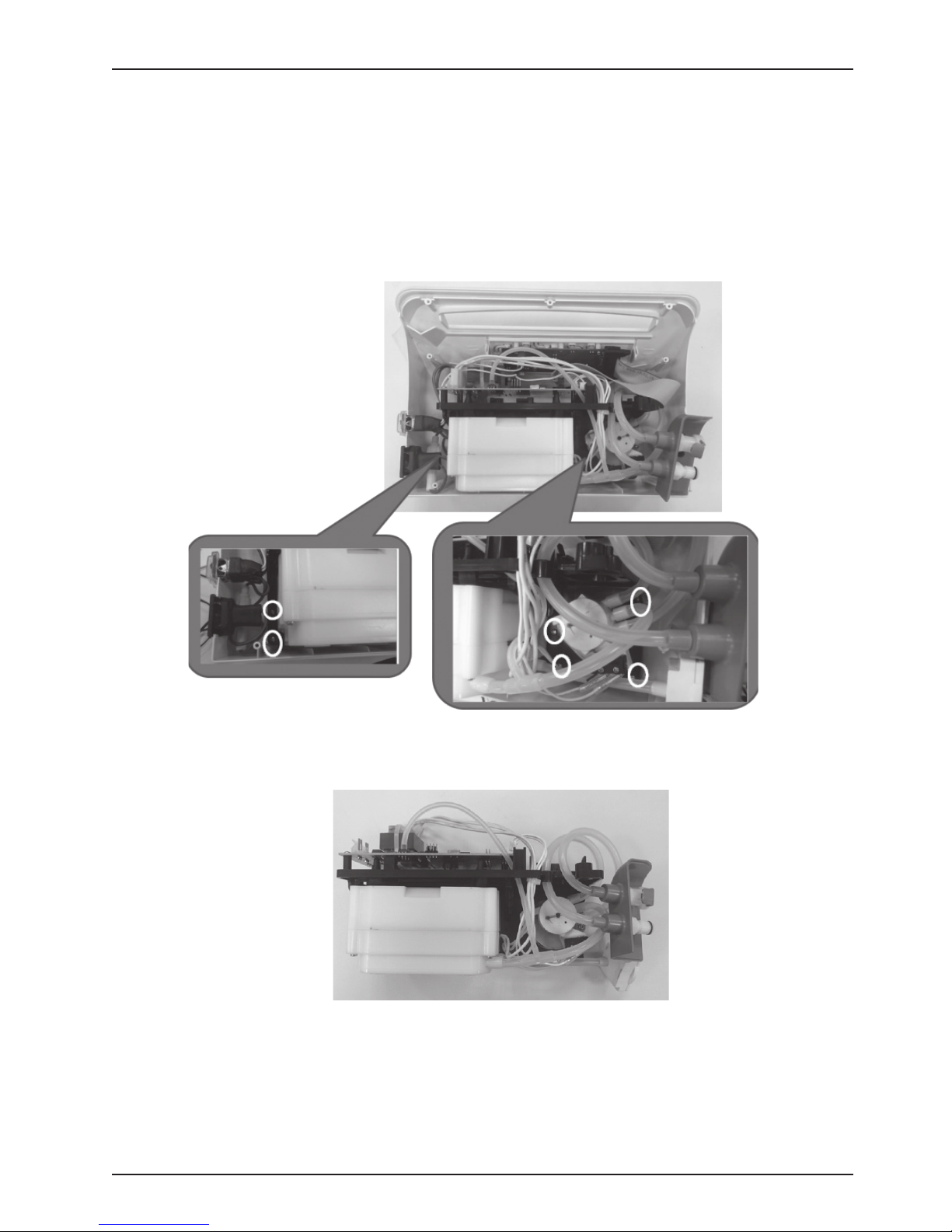
PUMPING SET REPLACEMENT
TOOLS REQUIRED:
● Phillips screwdriver for M3 screws
● Threadlocker (LOCTITE 290)
PROCEDURE:
1. Take out the 8 rubbers and remove 8 screws on the rear case. Take off the rear case.
2. Remove 6 screws on the base.
3. Remove wire connections to power switch and front panel PCBA. Take out the module set from the
case.
4. Pumping set is inside the compressor. Unscrew the 4 screws on the compressor and open the case.
5. Remove the screw of pumping set.
6. Take out the pumping set.
www.stryker.com 836 00 4 -5 210 V1.1 3
Page 6
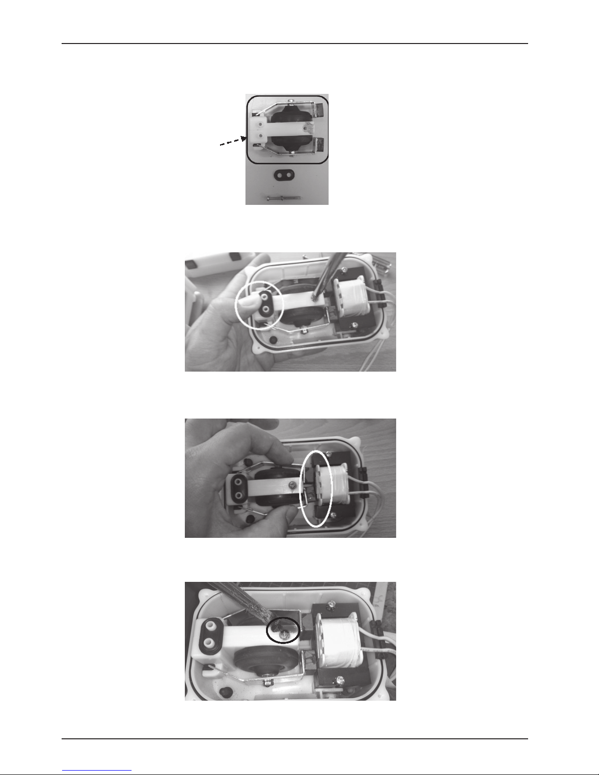
Service
7. Keep the rubbers, screw, and washer. Replace pumping set with a new one and discard the old one.
Assemble the pumping set:
1. Use your thumb to push back the pumping set and hold on this position, and then tighten the screw.
2. Press the vibration rods to make sure they will not touch the front object.
3. Apply threadlocker around the screw to set for the best bond.
4 836 00 4 -5 210 V1.1 www.stryker.com
Page 7
Service
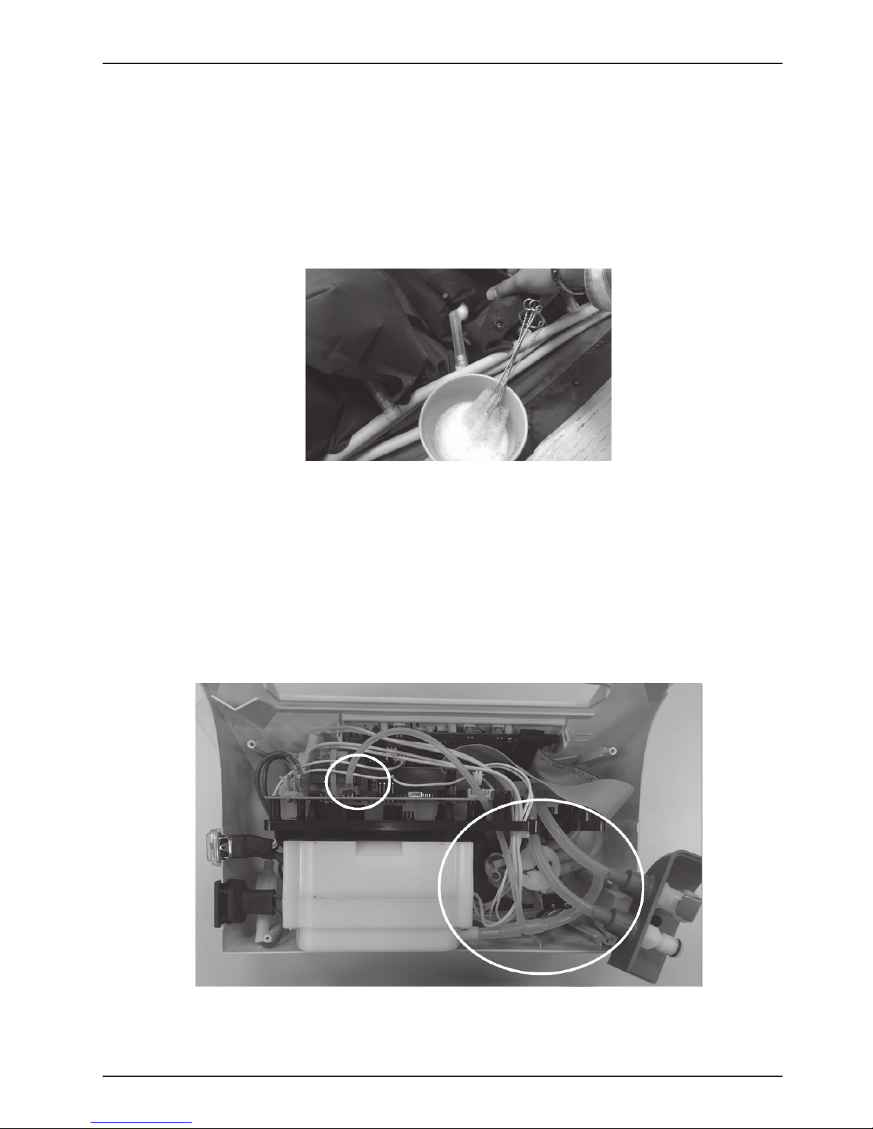
AIR CELL REPLACEMENT
TOOLS REQUIRED:
● Soap water and a container
PROCEDURE:
1. Infalte the air cells. Wipe soap water on the air cells.If you see bubbles on the air cells, there is an air
leakage. If there is a leakage, replace the air cell.
Photo is for reference only.
CHECK INTERNAL TUBING
TOOLS REQUIRED:
● Phillips screwdriver for M3 screws
PROCEDURE:
1. Remove the 8 rubber stops. Using a Philips screwdriver, remove the 8 screws that hold the rear case.
Remove the rear case.
2. Inspect for the tubing connections. Make sure that each tube is attached to its connector.
www.stryker.com 836 00 4 -5 210 V1.1 5
Page 8
Service
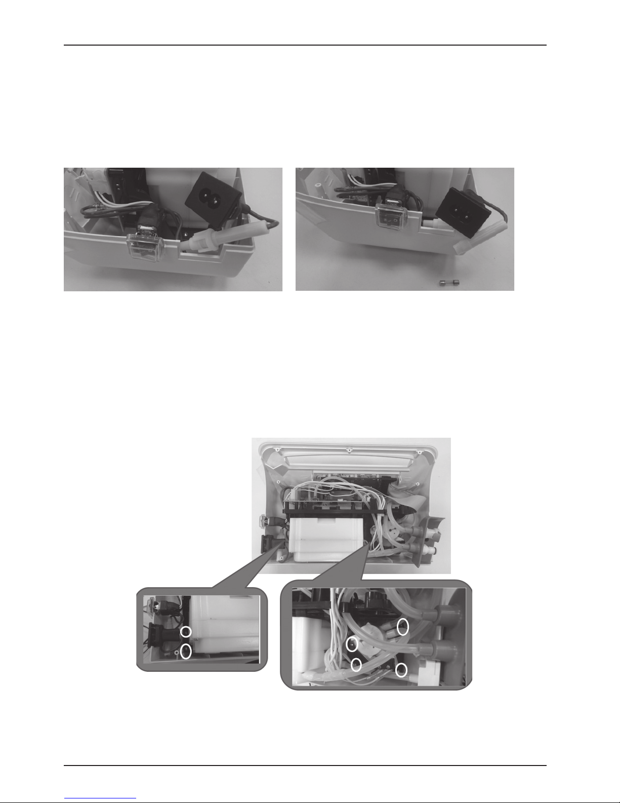
FUSE REPLACEMENT
PROCEDURE:
1. Remove the 8 rubber stops. Using a Philips screwdriver, remove the 8 screws that hold the rear case.
Remove the rear case.
2. Push the fuse holder together with turning counterclockwise to open it.
3. Replace the fuse and discard the old one.
MAIN PCBA REPLACEMENT
TOOLS REQUIRED:
● Phillips screwdriver for M3 screws
PROCEDURE:
1. Remove the 8 rubber stops. Using a Philips screwdriver, remove the 8 screws that hold the rear case.
Remove the rear case.
2. Remove 6 screws on the base.
6 836 00 4 -5 210 V1.1 www.stryker.com
Page 9

Service
3. Remove wire connections between power switch and main PCBA, front panel PCBA and main PCBA .
Take out the module set from the case.
4. Remove the 2 screws and all wire connections on the main PCBA.
5. Take out the main PCBA. Replace with a new one and discard the old one.
6. The wire connections on the main PCBA are as below.
7. After replacement, perform pressure calibartion. Refer to Pressure Calibration section.
www.stryker.com 836 00 4 -5 210 V1.1 7
Page 10

Service
TIMING MOTOR MODULE REPLACEMENT
TOOLS REQUIRED:
● Phillips screwdriver for M3 screws
PROCEDURE:
1. Remove the 8 rubber stops. Using a Philips screwdriver, remove the 8 screws that hold the rear case.
Remove the rear case.
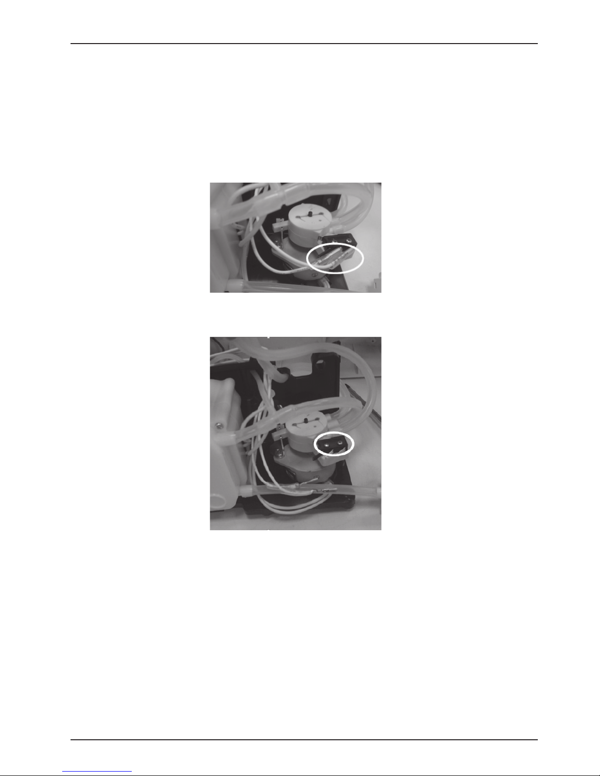
2. Remove the tubes and wire connections from timing motor module.
3. Remove the 2 screws on the motor assembly.
4. Remove the wire of timing motor module from the main PCBA.
5. Take out the timing motor module. Replace with a new one and discard the old one.
8 836 00 4 -5 210 V1.1 www.stryker.com
Page 11
Service
MICRO SWITCH REPLACEMENT
TOOLS REQUIRED:
● Phillips screwdriver for M3 screws
PROCEDURE:
1. Remove the 8 rubber stops. Using a Philips screwdriver, remove the 8 screws that hold the rear case.
Remove the rear case.
2. Remove the wire connections from micro switch.
3. Remove the 2 screws on the micro switch and then take out the micro switch. Replace with a new one
and discard the old one.
www.stryker.com 836 00 4 -5 210 V1.1 9
Page 12

Service
FRONT PANEL PCBA REPLACEMENT
TOOLS REQUIRED:
● Phillips screwdriver for M3 screws
PROCEDURE:
1. Remove the 8 rubber stops. Using a Philips screwdriver, remove the 8 screws that hold the rear case.
Remove the rear case.
2. Remove the tubes and wire connections from front panel PCBA.
3. Remove the 5 screws on the front panel PCBA.
FILTER REPLACEMENT
PROCEDURE:
1. Open the filter case. 2. Take out the filter. Replace with a new one and discard the old one.
10 836 00 4 -5 210 V1.1 www.stryker.com
Page 13

Service
PRESSURE CALIBRATION
TOOLS REQUIRED:
● Phillips screwdriver for M3 screws
● Syringe
● Pressure meter
● Tubing
Note: Pressure Meter suggested
Specification
±2psi or ±5psi range
Resolution: 0.001psi
Accuracy: ±0.3% FS
PROCEDURE:
1. Take out the 8 rubbers and unscrew 8 screws on the rear case. Remove the rear case.
2. Connect the deivce to power supply and switch on power switch.
3. In order press ABCA, then it goes into calibration mode.
ABC
4. For timing motor to be in position, there will be a long beep.
5. Press “A”. There will be a long beep.
6. After 10 seconds, press “A” again. There will be a long beep.
7. Remove the sensor tube from the main PCBA.
8. Connect the tubing of the calibration tool onto the sensor on the main PCBA.
www.stryker.com 836 00 4 -5 210 V1.1 11
Page 14

Service
9. Push (or pull) the loading piece of the syringe until the pressure meter shows and holds 10 mmHg, and
then press “A”. There will be a long beep.
10. Push (or pull) the loading piece of the syringe until the pressure meter shows and holds 33 mmHg, and
then press “A”. There will be a long beep.
11. Push (or pull) the loading piece of the syringe until the pressure meter shows and holds 63 mmHg, and
then press “A”. There will be a long beep. After about 5 seconds, another long beep (total 2 beeps). The
calibration is completed.
12. Switch off the power.
13. Remove the calibration tubing and put the sensor tube on senor.
14. Close the rear case and tighten all screws.
Note: Once you displace the main PCBA, you must complete the pressure calibration and pressure
test.
12 8 36 004 -5210 V1.1 ww w.stryker.com
Page 15
Service
PRESSURE TEST
TOOLS REQUIRED:
● Air cells with air loss x2
● Pressure meter
● PVC tubes and connector.
Note: Pressure Meter suggested
Specification
±2psi or ±5psi range
Resolution: 0.001psi
Accuracy: ±0.3% FS
PROCEDURE:
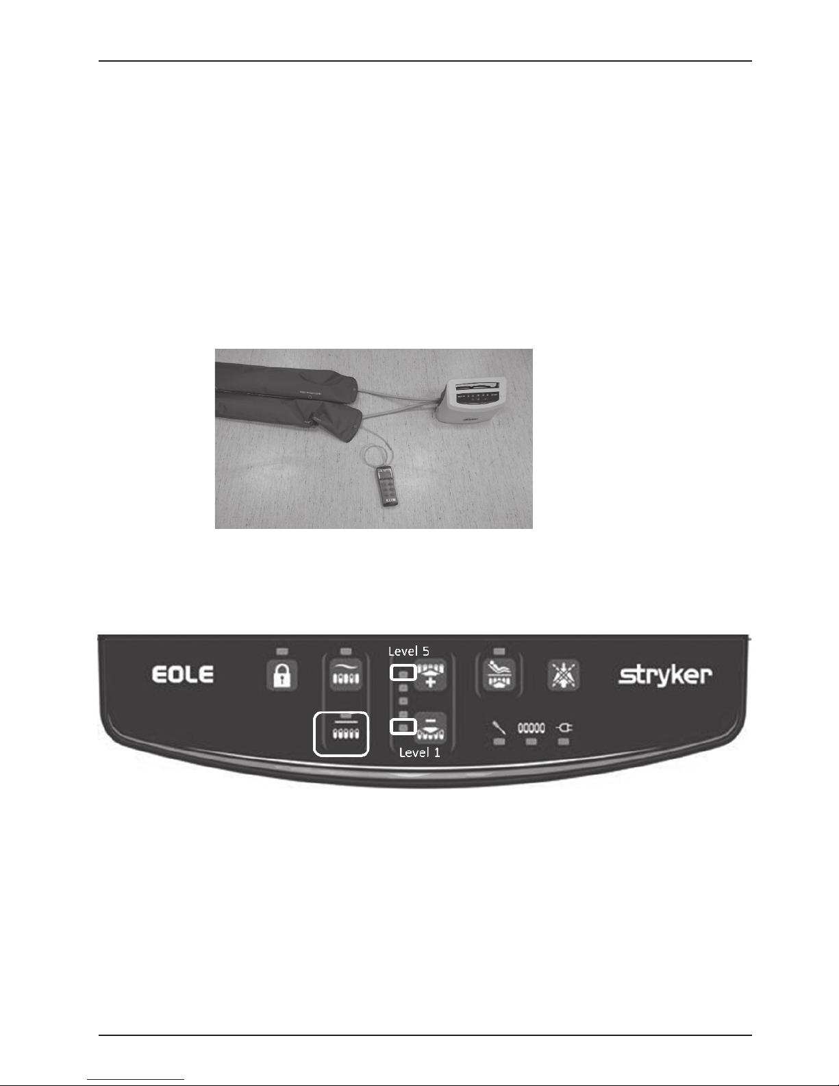
1. Connect the pressure test tool to the pump.
Photo is for reference only
2. Switch on power
3. After inflation is completed, change mode to “Static”.
4. Choose leve1, and after the pressure is stable, check the pressure meter. The pressure should be 20 ±
3 mmHg.
5. Choose level 5, and after the pressure is stable, check the pressure meter. The pressure should be 32
± 5 mmHg.
Note: If the pressure is out of range, please repeat the calibration process.
www.stryker.com 836 00 4 -5 210 V1.1 13
Page 16

Stryker Medical
3800 E. Centre Avenue
Portage, Michigan 49002
USA
Stryker European Operations B.V.
Herikerbergweg 110
Amsterdam
110 1 CM
Netherlands
2 017/10
836 00 4 -5 210 V1.1
www.stryker.com
 Loading...