

Page 1
Detachable
see back of manual
Quick Reference Guide
CUB®
Pediatric Crib
REF
FL19F/H (190)
Operations Manual
2014/10 B.0 1900-009-001 REV B www.stryker.com
Page 2

Page 3

Symbols
Warning/Caution, consult accompanying documentation
Safe Working Load Symbol
Type BF device
Battery-powered device with internal electrical source.
IPX4
REF
Protection from liquid splash
Direct Current
In accordance with European Directive 2002/96/EC on Waste Electrical and Electronic Equipment, this
symbol indicates that the product must not be disposed of as unsorted municipal waste, but should be
collected separately. Refer to your local distributor for return and/or collection systems available in your
country.
Model
Manufacturer
Page 4

Page 5

Table of Contents
Symbols ............................................................................... 1-1
Warning / Caution / Note Definition ...........................................................1- 5
Introduction ............................................................................1- 6
Intended Use ........................................................................ 1-6
Brief Product Description and Intended Use Statement .........................................1-6
Specifications ....................................................................... 1-7
Environmental Conditions...............................................................1- 8
Product Illustration....................................................................1- 9
Contact Information ...................................................................1-10
Summary of safety precautions..............................................................1-1 1
Setup.................................................................................1-13
Rail Verification (OPTIONAL) ............................................................1-13
Access Door Verification (OPTIONAL) .....................................................1-13
Scale Verification (optional) .............................................................1-13
Base Control Verification ...............................................................1-14
Litter Movement Verification.............................................................1-14
Other Equipment:.....................................................................1-14
Operation..............................................................................1-15
Base Controls .......................................................................1-15
Applying or Releasing the Brakes.........................................................1-16
Operating the Directional Fifth Wheel (Optional) ..............................................1-16
Raising or Lowering the Litter (Optional) - FL19H Only .........................................1-17
Trendelenburg / Reverse Trendelenburg (Optional) - FL19H Only..................................1-17
Operating the Fowler / Foot Sections ......................................................1-18
Manual Fowler Positioning ..............................................................1-18
Pneumatic Fowler Positioning............................................................1-18
Foot Section Positioning................................................................1-18
Operating the Siderails.................................................................1-19
Operating Access Doors (Optional) .......................................................1-19
Operating the Scale (Optional).......................................................... 1-20
Battery Replacement ................................................................. 1-2 2
Accessories ........................................................................... 1-2 3
Standard Accessory Bracket Usage ...................................................... 1-2 3
Premium Accessory Bracket Usage (Optional) .............................................. 1-2 3
Oxygen Bottle Clamp Usage (Optional).................................................... 1-2 4
Operating the IV Caddy (Optional) ....................................................... 1-2 4
Operating The Two-Stage Fixed IV Pole (Optional) ........................................... 1-25
Operating the Three-Stage IV Pole (Optional) ............................................... 1-2 6
Chart Holder / Monitor Holder Usage (Optional) ............................................. 1-27
Retracting Protective Top Installation (FA64074-BIL) .......................................... 1-2 8
Retracting Protective Top Operations (FA64074-BIL).......................................... 1-29
Retracting Protective Top Cleaning....................................................... 1-29
English
www.stryker.com 1900-009-001 REV B 1-3
Page 6

Table of Contents
English
Accessories (Continued)
Protective Top with Supports Installation (FA64183-BIL)........................................ 1-3 0
Protective Top With Supports Operations (FA64183-BIL) ....................................... 1-3 1
Protective Top with Supports Cleaning .................................................... 1-31
Cleaning.............................................................................. 1-32
Recommended Cleaning Method ........................................................ 1-3 2
Recommended Disinfectants ........................................................... 1-3 2
RINSE OFF CORROSIVE CLEANERS..................................................... 1-3 2
Special Instructions . . . . . . . . . . . . . . . . . . . . . . . . . . . . . . . . . . . . . . . . . . . . . . . . . . . . . . . . . . . . . . . . . . 1-33
REMOVAL OF IODINE STAINS .......................................................... 1-33
Preventive Maintenance ..................................................................1-3 4
Checklist .......................................................................... 1-3 4
Recycling passport ...................................................................... 1-3 5
Limited Warranty .................................................................... 1-3 6
Warranty exclusion and damage limitations................................................. 1-3 6
To obtain parts and service ............................................................ 1-3 6
Return Authorization.................................................................. 1-36
Damaged Merchandise ............................................................... 1-36
International Warranty Clause........................................................... 1-3 6
CUB Crib Quick Reference Guide ........................................................... 1-3 9
Base Controls ...................................................................... 1-41
Applying the Brakes.................................................................. 1-41
Raising / Lowering Litter (Optional) - FL19H Only ............................................ 1- 41
Trendelenburg / Reverse Trendelenburg (Optional)
- FL19H Only .......................................................................1- 41
1-4 1900-009-001 REV B www.stryker.com
Page 7

Warning / Caution / Note Definition
The words Warning, Caution and Note carry special meanings and should be carefully reviewed.
WARNING
Alerts the reader about a situation, which if not avoided, could result in death or serious injury. It may also describe
potential serious adverse reactions and safety hazards.
CAUTION
Alerts the reader of a potentially hazardous situation, which if not avoided, may result in minor or moderate injury to the
user or patient or damage to the equipment or other property. This includes special care necessary for the safe and
effective use of the device and the care necessary to avoid damage to a device that may occur as a result of use or
misuse.
Note
This provides special information to make maintenance easier or important instructions clearer.
English
Return To Table of Contents
www.stryker.com 1900-009-001 REV B 1-5
Page 8

Introduction
English
INTENDED USE
This manual is designed to assist you with the operation of the Stryker Model FL19 CUB® Pediatric Stretcher. It is
extremely important for the patient’s safety to read and understand all the information in this manual before operating
the stretcher. The manual must be available at all times to hospital staff for reference.
This Operations Manual is an integral part of the stretcher and should be included if the unit is sold or transferred.
BRIEF PRODUCT DESCRIPTION AND INTENDED USE STATEMENT
INTENDED MEDICAL INDICATIONS: The Stryker Cub Pediatric Crib is a pediatric hospital bed/stretcher intended for
medical purposes that consists of a bed or crib designed for the use of a pediatric patient, with fixed end rails and
movable and latchable siderails. The contour of the bed surface may be adjustable.
INTENDED PATIENT POPULATION: The safe working load indicates the sum of the patient, the mattress, and
accessory weight. The safe working load for Cub is 100lb (45 kg). This crib is not intended for use for any patient
measuring greater than 35 inches.
INTENDED PART OF THE BODY: The Stryker Cub Pediatric Crib is intended to support a patient while meeting safe
working loads. The patient can come in contact with the crib, but should never be placed on the frame without a sleep
surface. Cub is intended to be used with a 4 in. sleep surface, a thicker sleep surface or overlay that offers therapeutic
value. The crib should be used with extra caution. Patient supervision is suggested.
INTENDED USER PROFILE: The Stryker Cub Pediatric Crib is for patient use in acute Care settings, including
emergency departments, critical care, step down, progressive care, med/surg, sub-acute care, post anesthesia care
unit (PACU) or other locations in a professional healthcare facility as prescribed by a healthcare professional. Cub is
not intended to be used in a home healthcare environment. The typical operator for Cub would be trained healthcare
professionals.
INTENDED CONDITION OF USE AND EXPECTED LIFE: The Stryker Cub Pediatric Crib is designed for a 10 year
expected service life under normal use, conditions, and with appropriate periodic maintenance as described in the
maintenance manual for each device. Stryker warrants to the original purchaser that the welds will be free from
structural defects for the expected 10 year life of the product as long as the original purchaser owns the product.
Return To Table of Contents
1-6 1900-009-001 REV B www.stryker.com
Page 9

Introduction
SPECIFICATIONS
Model FL19H
190 Hydraulic Base
Safe Working Load 100 lb (45 kg) 100 lb (45 kg)
Overall Length & Width
• No Accessory Supports
• With Accessory Supports
65.5 in. x 37 in. (166 x 94 cm)
72.25 in. x 37.5 in. (184 x 95 cm)
65.5 in. x 37 in. (166 x 94 cm)
72.25 in. x 37.5 in. (184 x 95 cm)
Weight Capacity 400 lb (181 kg) 400 lb (181 kg)
Overall Weight (without options) 375 lb (170 kg) 310 lb (140,6 kg)
Height Range (to litter top)
• High
• Low
40 in. (102 cm)
33 in. (84 cm)
33 in. (84 cm)
33 in. (84 cm)
Litter Positioning
• Manual Activated
• Pneumatic Assist
• Trend./Reverse Trend.
• Foot Section Angle
0° / 25° / 40° / 55°
-
0°
50°
+/- 9.5°
0° / 6° / 12°
0° / 25° / 40° / 55°
-
0°
0° / 6° / 12° with manual foot prop
0° / 6° / 12°
Patient Surface 29.5 in. x 57 in. (75 x 145 cm) 29.5 in. x 57 in. (75 x 145 cm)
Caster Diameter 6 in. (15 cm) 5 in. (13 cm)
Brake System Four Wheel Ring Brake System Four Locking Casters
Capacity Patients weighing 4 lb (1.8 kg) to 100 lb (54.4 kg)
Perform scale measurement when unit is flat:
Scale (Optional)
Accuracy
Power
System
Electrical
Rating
± 0.5 lb (0.2 kg) at 50 lb (22 kg) or less
± 1.0 lb (0.4 kg) at ≥ 50 lb (22 kg)
Battery operated - 4 x “C” Type, Alkaline, 1.5VDC
6 VDC, 0.15 A
Model FL19F
190 Fixed Height Base
50°
English
Stryker provides special attention to product improvement and reserves the right to change specifications without
notice.
Compliant with the following standards: CSA C22.2, No. 60601.1; UL2601-1; IEC/EN 60601-1.
Note: The Cub® is CE Mark only without the scale option.
Return To Table of Contents
www.stryker.com 1900-009-001 REV B 1-7
Page 10

Introduction
English
ENVIRONMENTAL CONDITIONS
* Operating environment recommended to ensure scale precision.
Environmental Conditions Operation * Storage and Transportation
Ambient Temperature
Relative Humidity
(Non-Condensing)
Atmospheric Pressure
60 0F
(15.5 0C)
0%
700 hPa
85 0F
(29.1 0C)
95%
1060 hPa
122 0F
(50 0C)
-22 0F
(-30 0C)
95%
0%
1060 hPa
500 hPa
Return To Table of Contents
1-8 1900-009-001 REV B www.stryker.com
Page 11
(
)
(
)
(OPTIONAL)
(OPTIONAL)
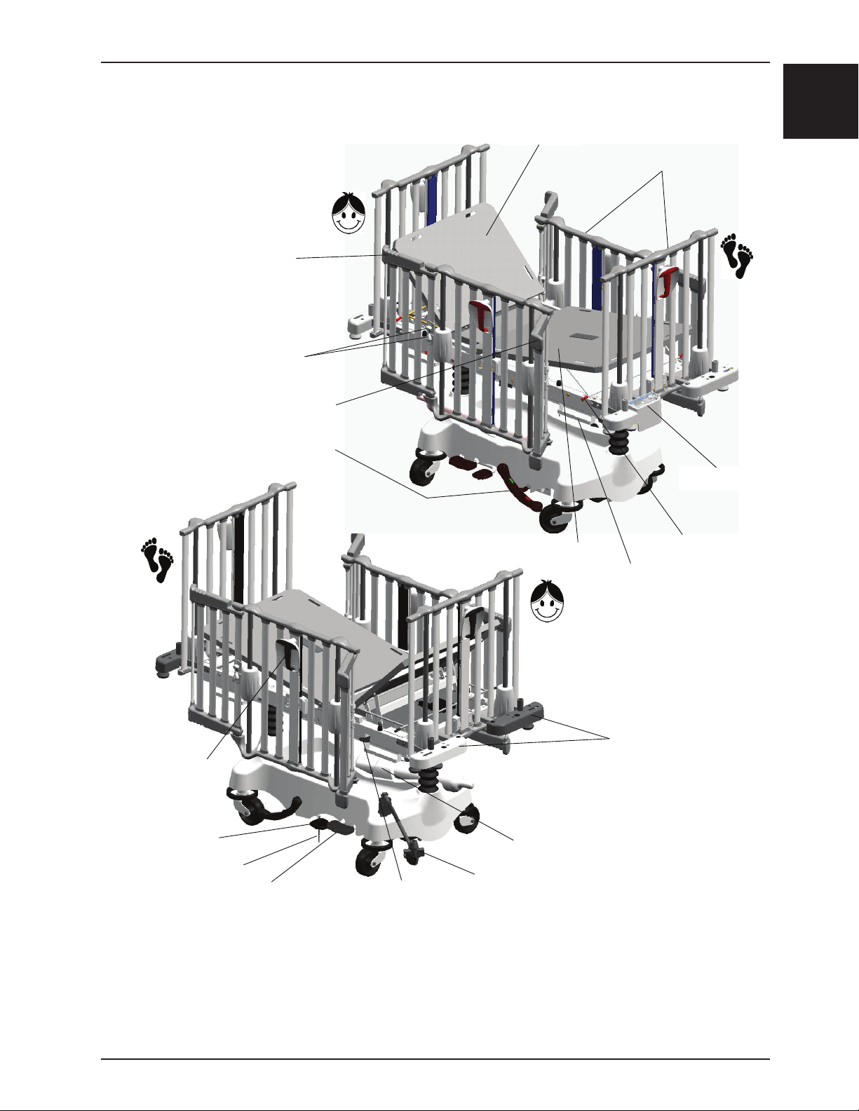
PRODUCT ILLUSTRATION
OPTIONAL ACCESS DOOR
ACCESS DOOR RELEASE KNOBS
(OPTIONAL)
OPTIONAL ACCESS DOOR
BRAKE / STEER PEDAL
OPTIONAL
(OPTIONAL)
Introduction
FOWLER
SIDE AND END RAILS
SCALE MODULE
English
OPTIONAL
SIDERAIL ACTIVATION
HANDLE
LITTER LIFT PEDAL
OPTIONAL
(
GROUND CHAIN
)
UNI-LOWER PEDAL
PNEUMATIC HEAD SECTION
ACTIVATION LEVER
OXYGEN BOTTLE RETAINING COLLAR
IV CADDY ARM (OPTIONAL
FOOT SECTION
)
FOOT SECTION SUPPORT
DRAINAGE BAG HOOK
HEAD PREMIUM ACCESSORY
(
BRACKETS
OPTIONAL
ARM
)
Figure 1 - Bed illustration
Return To Table of Contents
www.stryker.com 1900-009-001 REV B 1-9
Page 12

Introduction
English
CONTACT INFORMATION
Contact Stryker Customer Service or Technical Support at 1-800-327-0770.
Stryker Medical
3800 E. Centre Avenue
Portage, Michigan 49002
USA
Return To Table of Contents
1-10 1900-009-001 REV B www.stryker.com
Page 13

Summary of safety precautions
Before operating the Cub® Pediatric Stretcher, it is important to read and understand all information in this manual.
Carefully read and strictly follow the safety precautions listed on this page. The safety precautions are repeated
throughout the manual, where applicable.
WARNING
• Hospital staff should ensure a safe environment to the patient by verifying that the stretcher components (rails,
access doors, accessories, etc.) are in good condition and properly secured before placing a patient on the
stretcher.
• Always apply the brakes when a patient is removed from or placed on the stretcher. Always engage the brakes
unless the stretcher is being moved. Push on the stretcher to ensure the brakes are securely locked. Injury could
result if a stretcher moves while a patient is placed or removed from the stretcher.
• When brakes are applied on a fixed height stretcher, be sure all four casters are locked to ensure a complete
immobilization of the stretcher.
• To reduce risk of injury, ensure the litter is horizontal and in the lowest position with the rails fully raised when
moving the pediatric stretcher with a patient on it.
• The rails must always remain in the highest position and the litter in the lowest position unless the patient is being
tended. Never leave a patient unattended when the rails are lowered.
• Make sure that proper policies are applied to ensure the patient’s safety when an IV pole and/or an oxygen bottle
is used. The patient should not be able to reach nor manipulate them.
• To prevent possible fire hazard when using an oxygen tent on a stretcher equipped with the scale system (optional),
do not activate the scale. Also ensure that the rails are outside the tent.
• To avoid injury to the patient and/or the user, ensure the rails are in their highest position before lowering the litter
or placing it in one of the Trendelenburg positions, and that all equipment and people are removed from the area
below and around the litter.
• To avoid falls and injury, verify the rails and access doors are properly locked into position before leaving a patient
unattended or after having moved a rail or an access door.
• To avoid injury to the patient, ensure the patient’s extremities are clear of all moving parts before operating a rail.
Always ensure the rail is securely locked after moving it.
• To avoid falls and injury, ensure that both access door open/close indicators (located on both lock release knobs)
show green when the door is closed and locked into position.
• Avoid using an access door or a rail handle as push/pull devices or damage to the unit or injury to the patient and/
or user may occur.
• To avoid injury to the patient and/or user, do not attempt to move the stretcher directly sideways with the steer
mode engaged. The fifth steer wheel cannot pivot.
• To avoid injury to the patient, verify the patient is safely positioned on the litter before lowering the siderail or
operating the Fowler or foot section.
• To avoid injury to the patient when raising or lowering the manual Fowler or the foot section, verify the support arm
is securely engaged in the arm stoppers before releasing the Fowler or foot section.
• When patient is able to climb out the stretcher or reaches the height of 35 in. (90 cm), the stretcher shall no longer
be used.
• Do not place cords, straps or similar items that could become wound around the patient’s neck in or near the
stretcher.
• Do not leave objects or toys in the stretcher.
• Do not use a water mattress with this stretcher.
• To avoid injury to the patient, any mattress used on this stretcher must be at least 57 1/2 in. (146.05 cm) long by
29 3/8 in. (74.6 cm) wide and not less than 3 in. (7.6 cm) or more than 6 in. (15.3 cm) thick.
• Failure to properly clean the mattress, or dispose of it if defective, may increase the risk of exposure to pathogenic
substances and may bring about diseases to the patient and/or the user.
• Do not use the stretcher if any components are missing or broken. Contact your dealer or Stryker for replacement
parts. Use only replacement parts provided by Stryker.
• Maximum static weight capacity = 400 lb (181.4 kg).
English
Return To Table of Contents
www.stryker.com 1900-009-001 REV B 1- 11
Page 14

Summary of safety precautions
English
CAUTION
• To avoid damage to the scale electronic components, do not lean on the accessory bracket housing the scale
module.
• Do not use a two or three stage fixed IV pole at the foot end of a stretcher equipped with the scale.
• The scale weighing zone is made up of all the upper part of the stretcher, including the safety end/siderails, the
accessory brackets, the drainage bag hooks, the chart and monitor holders (optional) located under the mattress
support. Ensure no external object is in contact with the stretcher during a weighing or when zeroing the scale.
• To maintain the scale accuracy, it is recommended to zero the scale at least once a week. Note that the patient
must be removed from the stretcher before zeroing the scale.
• Use only 1.5 VDC alkaline batteries. The use of batteries other than the one recommended may damage the scale
electronic components.
• Remove the batteries if the scale module or the stretcher is not used for long periods.
• Always store the IV Caddy when not in use to avoid damaging it when the stretcher is moved.
• The weight of the IV bags should not exceed 40 lb (18 kg).
• Do not install a two or three-stage fixed IV pole at the foot end of a stretcher equipped with the scale.
• Do not use the protective top as a push/pull device.
Note
• Throughout the manual, the words “right” and “left” refer to the right and left sides of a patient lying face up on
the stretcher.
Return To Table of Contents
1-12 1900-009-001 REV B www.stryker.com
Page 15

Setup
It is important to check that all the stretcher components operate properly before it is put into service.
Some stretchers are equipped with one or both fixed endrails. Since stretchers are shipped with all four rails down,
a special document describes the procedure to permanently install a fixed endrail. This document is part of the kit
provided for the fixed endrail positioning and is to be found in a plastic envelop on the mattress as well as detailed in
the Maintenance Manual.
RAIL VERIFICATION (OPTIONAL)
Refer to pa g e 1-19
1. Side/endrail handles operate properly, handle triggers and rotational movement operates smoothly.
2. Side/endrails raise and lower smoothly, and lock in the 9", 14" and upper positions when raised or lowered.
3. Side/endrails automatically stop at the 9" position when lowered without interruption (handle kept rotated to the left
or right while lowering the rail) from upper positions. Rotating the handle to the left or right further lowers the rail
from the 9" position to its lowest position under the mattress surface.
NOTE
On some stretchers, the 9" double safety lock may not be present.
ACCESS DOOR VERIFICATION (OPTIONAL)
Refer to pa g e 1-19
1. Release knobs operate properly.
2. Access doors open, close and lock properly.
3. Both release knob open/close indicators show green when the door is closed and locked, and yellow when the
door is open. Verify that the access doors are properly closed and locked when both open/close indicators show
green.
English
SCALE VERIFICATION (OPTIONAL)
Refer to page 1-20
1. Press and release the Weigh/On button. A weight will appear on the scale display four to ten seconds later. If the
stretcher is unstable while the scale tries to weigh, the unstable stretcher icon (see icon and note page 1-21) will
appear on the display. Repeat the current operation once the stretcher is stabilized. Next, press and keep pressed
during at least two seconds the Zero button. A 0.0 lb/kg weight should appear on the display four to ten seconds later.
NOTE: The scale automatically shuts off after a 30 seconds of inactivity, except during the Change Equipment
procedure where there is a three minute delay. To reactivate the scale, press the Weigh/On button.
2. The weight reading can be displayed in pounds (lb) or kilograms (kg). Press the lb / kg button to switch from a
weight reading unit to the other. The lb / kg button can be deactivated to prevent inadvertently changing scale
units. To do so, press and hold the lb / kg and Memory buttons for at least two seconds. To reactivate the lb / kg
button, repeat the operation.
3. Place a known weight on the mattress of the stretcher and press the Weigh/On button. A weight reading will be
displayed four to ten seconds later. Ensure the unit is flat and the weight displayed is accurate to ± 0.5 lb (0.2 kg)
at 50 lb (22 kg) or less and ± 1.0 lb (0.4 kg) at ≥ 50 lb (22 kg) of the actual weight.
4. The weight reading displayed can be stored. To do so, press the Weigh/On button. Press and hold the Memory
button for two seconds, and release the button when "Memory" appears on the screen. The weight previously
displayed by the scale should now be stored in memory.
5. The stored weight reading can be erased. To do so, press the Weigh/On button. Simultaneously press and hold the
Memory and Zero buttons for at least two seconds. The value stored is erased when the keys are released and
0.0 lb/kg is displayed on the screen.
6. Equipment can be added or removed from the stretcher when the patient is in it. Leave the patient on the stretcher
and press the Weigh/On button. A reading will appear on the display four to ten seconds later. Next, press the
Change Equipment button; "Change Equipment" will appear on the screen four to ten seconds later. Add or remove
the extra equipment to the stretcher and press the Change Equipment button. The weight of the initial load should
now be displayed within ± 0.5 lb (0.2 kg) at 50 lb (22 kg) or less and within ± 1.0 lb (0.4 kg) at ≥ 50 lb (22 kg) when
flat.
Return To Table of Contents
www.stryker.com 1900-009-001 REV B 1-13
Page 16

Setup
English
BASE CONTROL VERIFICATION
Refer to pa g e 1-14
1. Optional steer pedal operates properly. Fifth steer wheel operational with steer pedal (green side of the pedal)
engaged.
2. Optional brake pedal operates properly. All casters lock with brake pedal engaged (red side of the pedal).
3. Optional lift pedal operates properly. Litter raises and reaches maximum height (40" - 102 cm) when lift pedal is
pumped.
4. Trendelenburg positions and litter descent are operational when uni-lower pedal (optional) is depressed using
respectively the extremities and its centre.
5. All casters lock and swivel properly.
6. Fixed height stretcher (optional) four casters lock and unlock properly using the brake lever.
7. Litter Movement Verification (see section 2.6):
8. Optional assisted or manual Fowler operates properly.
LITTER MOVEMENT VERIFICATION
Refer to pa g e 1-14
1. Optional assisted or manual Fowler operates properly.
NOTE: To raise the assisted Fowler, a slight push under the top part of the Fowler is needed to start its rise;
to lower it, push down on its top part while lifting the activation lever.
2. Foot section support arm operates properly.
OTHER EQUIPMENT:
1. Ground chain secured to base.
2. Accessory brackets secure.
3. Optional IV Caddy arm (see page 1-24) secure and working properly.
4. Optional two or three-stage IV pole (see page 1-25 and page 1-26) secured to accessory bracket and is easily
stored on the adjacent accessory bracket.
5. Optional oxygen bottle clamp (see page 1-24) secured to hood.
6. Optional chart holder (see page 1-27) located under the mattress support secured to frame.
If any problems are found during bed setup, contact the Technical Service department at 1-800-327-0770.
Return To Table of Contents
1-14 1900-009-001 REV B www.stryker.com
Page 17

Operation
E
F
A
A
D B C
D
B
C
HEAD END
RIGHT
LEFT
BASE CONTROLS
Two types of base models are available: the Fixed Height and Variable Height (hydraulic).
English
Figure 2 - Base Controls
A
B
C
D
E
Pump to raise litter.
Depress the center of pedal (B) to lower
both ends of the stretcher together.
Depress the side of pedal (B) closest
to the stretcher head end to lower the
head end.
Depress the side of pedal (B) closest
to the stretcher foot end to lower the
foot end.
Brake and Steer functions (left side)
Steer.
F
www.stryker.com 1900-009-001 REV B 1-15
Steer and Brake functions (right side).
Return To Table of Contents
Page 18

Operation
English
APPLYING OR RELEASING THE BRAKES
WARNING
• Always apply the brakes when a patient is removed from or placed on the stretcher.
• Always engage the brakes unless the stretcher is being moved. Push on the stretcher to ensure the brakes are
securely locked.
• Serious injury could result if a stretcher moves while a patient is placed or removed from the stretcher.
• If brakes do not hold properly, refer to your stretcher maintenance manual for the brake adjustment procedure.
Two types of base are available: the Hydraulic Base and the Fixed Height Base.
Note
Each of the two types of stretcher base available corresponds a different brake system: a pedal operated four-wheel
brake system for the optional hydraulic base and four separate locking casters for the fixed height base.
HYDRAULIC BASE
• To engage the brakes at the left side of the stretcher, push fully down on the left side of the pedal (E, page 1-15).
• To engage the brakes at the right side of the stretcher, push fully down on the right side of the pedal (F, page
1-15).
• To disengage the brakes at either side of the stretcher, move the pedal to neutral position.
FIXED HEIGHT BASE
A
WARNING
When brakes are applied, ensure all four casters are locked to ensure
complete stabilization of the stretcher.
• To engage the caster brakes, press fully down on all four caster
brake levers (A) (see Figure 3).
• To disengage the caster brake, push the opposite side of the brake
lever with your foot or lift up with your toe under the brake lever (see
Figure 3).
A A A
Figure 3 - Fixed Height Base
OPERATING THE DIRECTIONAL FIFTH WHEEL (OPTIONAL)
WARNING
• To reduce risk of injury, ensure the litter is horizontal and in the lowest position with the rails fully raised when
moving the pediatric stretcher with a patient in it.
• To avoid injury to the patient and/or user, or damage to the stretcher, do not attempt to move the stretcher directly
sideways with the steer mode engaged. The fifth steer wheel cannot pivot.
The purpose of the steer mode (fifth steer wheel) is to help guide the stretcher when transporting a patient along a
straight line and also for pivoting at corners.
• To engage the steer mode at the left side of the stretcher, push fully down on the right side of the pedal (E, page
1-15).
• To engage the steer mode at the right side of the stretcher, push fully down on the left side of the pedal (F, page
1-15).
• To disengage the steer mode at either side of the stretcher, move pedal to neutral position. Positioning the pedal
in neutral enables the stretcher to be moved in any directions, including sideways.
Return To Table of Contents
1-16 1900-009-001 REV B w ww.stryker.com
Page 19

Operation
RAISING OR LOWERING THE LITTER (OPTIONAL) - FL19H ONLY
WARNING
To avoid injury to the patient and/or the user, ensure the rails are in their highest position before lowering the litter or
placing it in one of the Trendelenburg positions, and that all equipment and people are removed from the area below
and around the litter.
Be sure to move any equipment that may be in the way before raising or lowering the litter.
• To raise the litter height, pump pedal (A, page 1-15) repeatedly until the desired height is achieved.
• To lower both ends of the litter together, depress the center of pedal (B, see page 1-15) until the desired height
is achieved. To lower only the head end of the litter, depress the side of pedal (B, page 1-15) closest to the head
end. To lower only the foot end of the litter, depress the side of pedal (B, page 13) closest to the foot end.
TRENDELENBURG / REVERSE TRENDELENBURG (OPTIONAL) - FL19H ONLY
NOTE
The litter height must be raised first in order to achieve a Trendelenburg position.
WARNING
To avoid injury to the patient and/or the user, ensure the rails are in their highest position before lowering the litter or
placing it in one of the Trendelenburg positions, and that all equipment and people are removed from the area below
and around the litter.
English
• For Trendelenburg positioning (head down), depress the side of pedal (B, page 1-15) closest to the stretcher
head end.
• For Reverse Trendelenburg positioning (foot down), depress the side of pedal (B, page 1-15) closest to the
stretcher foot end.
NOTE
The higher the litter is before a Trendelenburg positioning, the greater the Trendelenburg angle will be. (Maximum
Trendelenburg angles: +9.5° to -9.5°).
Return To Table of Contents
www.stryker.com 1900-009-001 REV B 1-17
Page 20

Operation
English
OPERATING THE FOWLER / FOOT SECTIONS
NOTE
Two types of Fowler are available: manually operated and pneumatic assisted. The foot section is manually operated.
WARNING
• To avoid injury, verify the patient is safely positioned on the litter before lowering the siderail and operating the
Fowler or foot section.
• To avoid injury when raising or lowering the manual Fowler or the foot section, verify the support arm is securely
engaged in the arm supports before releasing the Fowler or foot section.
MANUAL FOWLER POSITIONING
• To raise the Fowler, manually lift it up. As the Fowler is raised,
the support arm (A) will fall into position and engage the support
brackets into one of the three available angular positions: 25°, 40°
and 55° (see Figure 4).
• To adjust the Fowler angle, lift it up slightly with one hand and with
the other, lift one of the support arm handles (A) to disengage it
from the support brackets. Engage the support arm at the desired
position. To flatten the Fowler, hold the handle while lowering the
Fowler to flat and release the support (see Figure 4).
PNEUMATIC FOWLER POSITIONING
• To raise the Fowler, lift up the right or left activation lever (B)
while lifting the Fowler to the desired postion (see Figure 5),
and release the lever once the desired height is achieved.
• To lower the Fowler, push down on the Fowler while lifting up
the right or left activation lever (B) (see Figure 5). Release
the lever once the desired height is achieved.
FOOT SECTION POSITIONING
Fowler
A
Figure 4 - Fowler Positioning
Fowler
Foot Section
• To raise the foot section, lift it up manually. As the foot
section is raised, the support arm will fall into position and
B
C
engage the support brackets into one of the two available
angular positions: 6° and 12° (see Figure 5).
• To lower the foot section to the next position or to flat, lift it up
Pneumatic Fowler and Foot Positioning
Figure 5 -
with one hand and with the other lift one of the support harm
handles (C) to disengage it from the support brackets (see
Figure 5). Lower the foot section and release the support so
that it engages in the support brackets of the next position or
lower to flat, releasing the support only at the end.
Return To Table of Contents
1-18 1900-009-001 REV B w ww.stryker.com
Page 21

Operation
OPERATING THE SIDERAILS
WARNING
• To avoid injury, ensure the patient’s extremities are clear of all moving parts before operating a rail. Always ensure
the rail is securely locked after moving it.
• The rails must always remain in the highest position and the litter in the lowest position unless a patient is being
tended. Never leave a patient unattended when the rails are lowered.
• To avoid falls and injury, verify the rails and access doors are properly locked into position before leaving a patient
unattended or after having moved a rail or an access door.
NOTE
To ensure the rails are safely locked into position, verify that
the arrow pointers (B) are aligned.
• To raise a siderail/endrail, grasp the top bar or the handle
(A) and pull the rail up to the desired height. No turning of
the handle to any side is necessary. The rail will lock into
one of the three available positions: 9 in., 14 in. and 26 in.
A “click” will be heard as available locking positions are
crossed (see Figure 6).
• To lower a siderail/endrail, grasp the handle (A). Activate
the trigger, turn handle to the left or right and guide the
rail down to the desired height. Return the handle back to
vertical to lock the rail into desired position (see Figure 6).
A
English
NOTE
• For safety reasons, side/endrails automatically stop and
lock at the 9 in. position, even if the handle is kept turned
during the rail descent.
• On some stretchers, the double safety lock at 9 in. may not
be present.
OPERATING ACCESS DOORS (OPTIONAL)
WARNING
To avoid falls and injury, ensure the access door
open/close indicators (located on both release knobs)
show green when the door is closed and locked into
position.
• To open an access door, squeeze the two
release knobs (A) located on each access door
pivot bar and open the access door. The open/
close indicators (B) will show yellow (see Figure
7).
• To close an access door, return it back to the
closed position and it will automatically lock. The
open/close indicators (B) will show green. If one
of them remains yellow, it means that the door is
not completely closed; open and close the door
again (see Figure 7).
B
B
Figure 6 - Siderails / Endrails
A
Figure 7 - Access Door
Return To Table of Contents
www.stryker.com 1900-009-001 REV B 1-19
Page 22

Operation
D
C
E
A
B
F
English
OPERATING THE SCALE (OPTIONAL)
The scale system allows the reading of a patient’s weight in pounds (lb) or kilograms (kg) within ± 0.5 lb (0.2 kg) at 50
lb (22 kg) or less and within ± 1.0 lb (0.4 kg) at ≥ 50 lb (22 kg) when flat. The reading can be stored in memory. The
system also allows to add or remove a device or accessory from the stretcher without removing the patient.
SCALE CONTROL PANEL
CAUTION
• To avoid damage to the scale electronic components, do not lean on the accessory bracket housing the scale
module.
• Do not use a two or three stage fixed IV pole at the foot end of a stretcher equipped with the scale.
This table refers to Figure 8 above.
Activates the scale. A weighing is performed when this button is pressed and released.
A weight will be displayed on the display four to ten seconds later. However, no weight
is displayed if the Error -Ex.x or the movement
Weigh/On
A
Memory Stores the result of the weighing or recalls on display the weight stored.
B
Zero Zeroes the weight displayed on screen and the weight stored.
C
lb / kg Changes the unit of measurement (lb or kg).
D
Change Equipment To remove or add equipment from the stretcher without removing the patient.
E
Scale Display
F
error will have to be corrected or the stretcher stabilized before using the scale again
(see the Error Code List in the Maintenance Manual).
NOTE
The scale does not work in continuous mode. It must be activated using the Weigh/
On key each time a reading of the patient’s weight is required.
The scale will auto shut off after an inactivity period of 30 seconds, except during the
Change Equipment operation where three minutes are allowed. Press the Weigh/On
button to reactivate the scale.
If the patient weighs more than 100 lb (54 kg), the “Error - E05” message will appear
on the display to indicate that the scale should not be used in these conditions, as its
maximal weighing capacity is exceeded.
Some other error messages may be displayed while operating the scale. Refer to the
Error Code List in the Maintenance Manual to understand their signification and what
action to take when they appear.
Figure 8 - Scale Control Panel
icon appears on display. The
Return To Table of Contents
1-20 1900-009-001 REV B www.stryker.com
Page 23
Operation
SCALE OPERATION
CAUTION
The scale weighing zone is made up of all the upper part of the stretcher, including the safety end/siderails, the accessory
brackets, the drainage bag hooks, the chart and monitor holders (optional) located under the mattress support. Ensure
no external object is in contact with the stretcher during a weighing or when zeroing the scale.
NOTE
The
the patient’s weight because the stretcher is unstable. Simply stabilize the stretcher and repeat the current operation.
The Memory, Change Equipment and Zero keys may be used to stop the weight reading process when the operation
currently used does not need a weight reading to be displayed.
icon may appear at any time when using the scale. It indicates that the scale is unable to take a reading of
A. PREPARING (ZEROING) THE SCALE FOR A NEW PATIENT
• Prepare the stretcher for the new patient (sheets, pillows, equipment, etc.).
• Press and release the Weigh/On button to activate the scale. A weight reading will appear on the display
four to ten seconds later during which a three-hyphen line will flash.
• Press and keep pressed the Zero button during at least two seconds. Release the key; the weight
displayed and the weight stored will be zeroed four to ten seconds later.
• With the patient in the stretcher, press the Weigh/On button. The patient’s weight will be displayed four
to ten seconds later.
English
CAUTION
To maintain the scale accuracy, it is recommended to zero the scale at least once a week. Note that the patient must be
removed from the stretcher before zeroing the scale.
B. STORING IN MEMORY A WEIGHT READING
• Press the Weigh/On button to activate the scale. Wait for the reading to be displayed.
• Press and hold the Memory button for two seconds. Release the button when the “Memory” message
appears on the display. The weight previously displayed is now stored.
C. RECALLING ON DISPLAY THE WEIGHT STORED IN MEMORY
• Press the Weigh/On button to activate the scale. Do not wait for the weight to be displayed, proceed
immediately with the next step.
• Press the Memory button. The value stored will be displayed along with “Memory”. To leave the Memory
mode, press the Weigh/On button.
D. ZEROING THE WEIGHT DISPLAYED AND STORED IN MEMORY
• Press the Weigh/On key to activate the scale. Do not wait for the weight to be displayed, proceed
immediately with the next step.
• Press and hold the Zero button for at least two seconds. Release the button; the weight displayed and the
weight stored will be zeroed four to ten seconds later.
E. ZEROING THE MEMORY ONLY
• Press the Weigh/On button to activate the scale. Do not wait for the weight to be displayed, proceed
immediately with the next step.
• Simultaneously press and hold the Memory and Zero buttons for at least two seconds and release. The
screen will display 0.0 lb/kg.
Return To Table of Contents
www.stryker.com 1900-009-001 REV B 1-21
Page 24
Operation
English
F. ADDING OR REMOVING EQUIPMENT WITH A PATIENT IN THE STRETCHER
• Press the Weigh/On button to activate the scale. You may proceed immediately with the next step, but if
you want to compare the weight reading resulting from the Change Equipment procedure with the patient’s
weight reading before the procedure, let the weigh process display a weight reading and note the weight.
• Press the Change Equipment button. The “Change Equipment” message will appear on the display four to
ten seconds later. NOTE: the scale will automatically shut off if this step takes more than three minutes.
The operation will then have to be started over.
• Add or remove the equipment on the stretcher. Then, press the Change Equipment button. The unchanged
patient’s weight will reappear on the screen four to ten seconds later.
NOTE
To prevent erroneous weight readings, the “Adding or Removing Equipment with a Patient in the Stretcher” procedure
must be completed each time an object is added or removed from the scale weighing zone.
G. CHANGING THE UNIT OF MEASUREMENT
• Press the Weigh/On button to activate the scale. A weight reading will appear on the display four to ten
seconds later.
• Press the lb /kg button to change from pounds (lb) to kilograms (kg) or conversely.
• The lb /kg button can be deactivated to prevent inadvertent use of the button. To do so, press and hold
the lb /kg and Memory buttons for at least two seonds. Do the same to reactivate the lb /kg button.
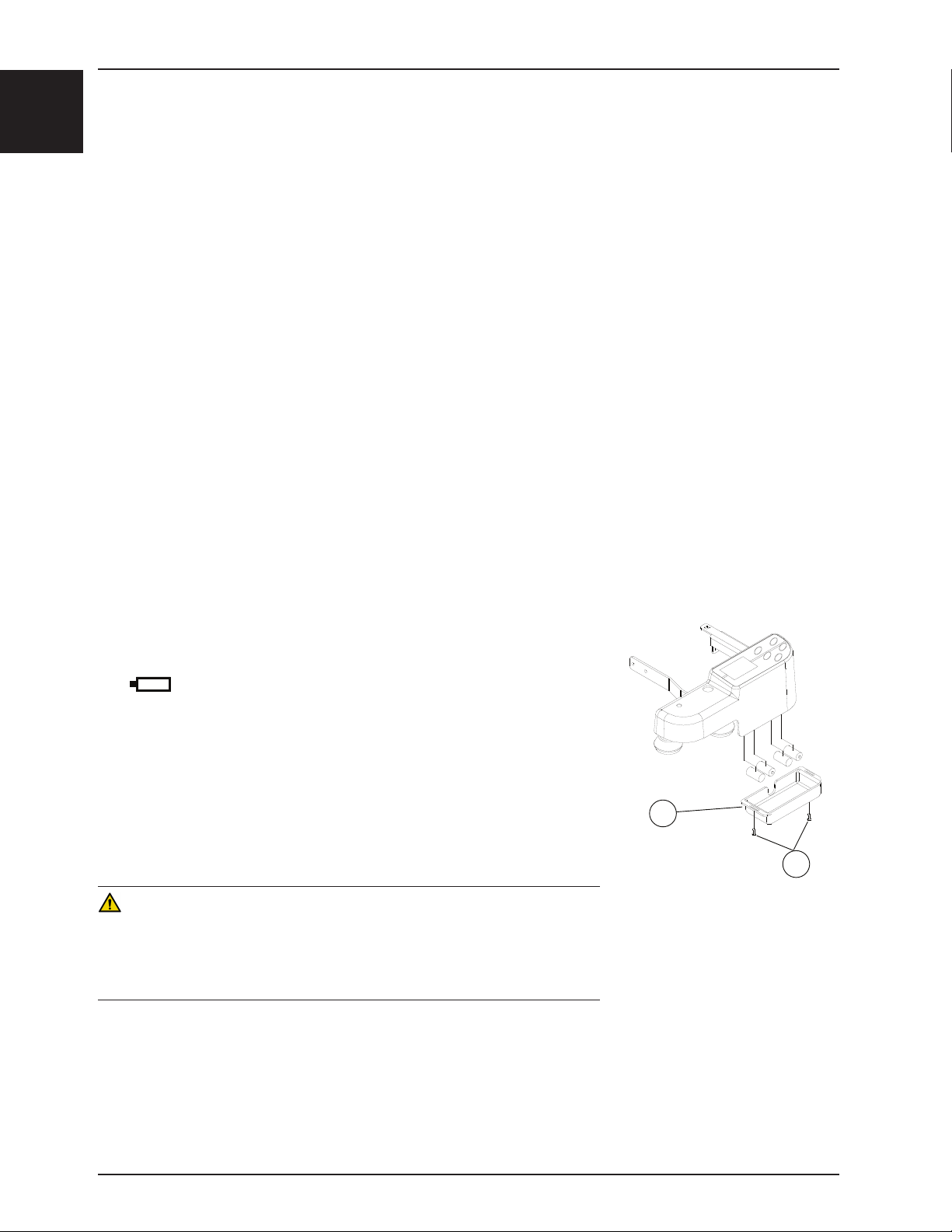
BATTERY REPLACEMENT
The electronic system of the scale is powered by four alkaline C type batteries (1.5 VDC). To replace them, refer to
Figure 9 and follow steps 1-4 below.
NOTE
The icon will appear on the display to notify that the batteries must be
replaced.
1. Using a #2 Phillips screwdriver, remove the 2 screws (A) holding the cover
(B) of the battery enclosure.
2. Remove the four batteries and replace them with four new alkaline C type
batteries (1.5 VDC). Ensure the batteries are installed with the proper polarity.
3. Replace the cover.
4. Zero the scale (see procedure A, previous page) without a patient in the
stretcher before returning it to service.
CAUTION
• Use only 1.5 VDC alkaline batteries. The use of batteries other than the one
recommended may damage the scale electronic components.
• Remove the batteries if the scale module or the stretcher is not used for long
periods.
B
A
Figure 9 - Battery Replacement
Return To Table of Contents
1-22 1900-009-001 REV B www.stryker.com
Page 25

Accessories
BRACKET
STANDARD ACCESSORY BRACKET USAGE
Standard accessory brackets are installed at the four corners of the stretcher to support an optional vertical oxygen
bottle holder, optional removable IV poles and/or an optional retracting protective top. A convenient rubber bumper
completes the bracket assembly (see Figure 10).
PROTECTIVE TOP MOUNTING
SOCKET
RUBBER BUMPER
Figure 10 - Standard Accessory Bracket
REMOVABLE IV POLE INSTALLED
(
NOT INCLUDED
STANDARD ACCESSORY
)
English
PREMIUM ACCESSORY BRACKET USAGE (OPTIONAL)
The pediatric stretcher may be equipped with optional premium accessory brackets to hold different pieces of equipment
needed for patient care. Designed to be mounted at one or both ends of the stretcher, they come in set of two or four.
See Figure 11 for the bracket socket functions.
CAUTION
The scale weighing zone is made up of all the upper part of the stretcher, including the safety end/siderails, the accessory
brackets, the drainage bag hooks, the chart and monitor holders (optional) located under the mattress support. Ensure
no external object is in contact with the stretcher during a weighing or when zeroing the scale.
PERMANENT IV POLE HANGER
STORAGE SOCKET
PERMANENT IV POLE
SOCKET
STRYKER
SOCKET
UPRIGHT O
HOLDER SOCKET
1/2
IV POLE
"
BOTTLE
2
PROTECTIVE TOP MOUNTING SOCKETS
REQUIRES SET OF FOUR ACCESSORY BRACKETS
(
OR
STRYKER ACCESSORY SOCKETS
)
UPRIGHT O
BOTTLE
2
HOLDER SOCKET
PERMANENT IV POLE HANGER
STORAGE SOCKET
PERMANENT IV POLE
SOCKET
STRYKER
1/2
SOCKET
"
IV POLE
Figure 11 - Premium Accessory Bracket
Return To Table of Contents
www.stryker.com 1900-009-001 REV B 1-23
Page 26

Accessories
A
English
OXYGEN BOTTLE CLAMP USAGE (OPTIONAL)
An oxygen bottle clamp (A) may be installed on the
base hood to secure an oxygen bottle installed in the
cavity provided on the hood (see Figure 12).
Slide the bottle into the cavity, bottom first.
OPERATING THE IV CADDY (OPTIONAL)
The IV Caddy enables an IV pole on casters to be transported when the stretcher is moved. Always ensure the IV Caddy
is secured tightly on the IV pole before transporting to avoid damaging the IV pole or causing injury to the patient or
user (see Figure 13).
1. Lift the IV Caddy from the storage clip.
2. Pivot the IV Caddy to the desired position.
3. Turn knob (A) counter clockwise to loosen the pole clamp (C).
4. Pivot the knob (A) away from the clamp (B). The clamp (C) may then be opened.
5. Place the IV pole into the clamp (B). Close the clamp (C) around the IV pole and pivot the knob (A) back into
position.
6. Turn the knob clockwise to tighten it. The IV pole is now ready to move with the stretcher.
7. To remove the IV pole from the IV Caddy, turn knob (A) counter clockwise to loosen the pole clamp.
8. Pivot the knob away from the clamp (B), open the clamp and remove the IV pole from the IV Caddy.
9. Store the IV Caddy.
Figure 12 - Oxygen Bottle Clamp
CAUTION
Always store the IV Caddy when not in use to avoid damaging it when the stretcher is moved.
Figure 13 - IV Caddy
Return To Table of Contents
1-24 1900-009-001 REV B www.stryker.com
Page 27

Accessories
OPERATING THE TWO-STAGE FIXED IV POLE (OPTIONAL)
WARNING
Make sure that proper policies are applied to ensure the patient’s safety when an IV pole and/or an oxygen bottle are
used. The patient should not be able to reach nor manipulate them.
To use the two-stage fixed IV pole refer to Figure 14 and follow steps 1-4 below:
1. Lift and pivot the pole from the storage position and push it down until it is locked into the receptacle.
2. To raise the height of the pole, pull up on the telescoping portion (A) until it locks into place at its fully raised
position. There are no intermediary positions for this section.
3. Rotate the IV pole hangers (B) to desired position and hang the IV bag.
4. To store the IV pole, turn the latch (C) clockwise until section (A) lowers. Lift up on the pole to remove it from its
receptacle, fold it and insert the hangers into the storage location provided on the adjacent accessory bracket.
English
Figure 14 - 2-Stage IV Pole
CAUTION
• The weight of the IV bags should not exceed 40 lb (18 kg).
• Do not install a two or three-stage fixed IV pole at the foot end of a stretcher equipped with the scale.
Return To Table of Contents
www.stryker.com 1900-009-001 REV B 1-25
Page 28

Accessories
English
OPERATING THE THREE-STAGE IV POLE (OPTIONAL)
WARNING
Make sure that proper policies are applied to ensure the patient’s safety when an IV pole and/or an oxygen bottle are
used. The patient should not be able to reach nor manipulate them.
To use the three-stage IV pole, refer to Figure 15 and follow steps 1-5 below:
1. Lift and pivot the pole from the storage position and push it down until it is locked into the receptacle.
2. To raise the height of the pole, pull up on the first telescoping portion (A) until it locks into place at its fully raised
position. There are no intermediary positions for this section.
3. For a higher IV pole, pull up on the second telescoping portion (B). Release the section (B) at any desired height
and it will lock into place. To lower the section, push up on the red part of the handle while holding the section and
lower the section to the desired height. Release the red part of the handle to lock the section into place.
4. Rotate the IV hangers (C) to the desired position and hang the IV bags.
5. To store the IV pole, push up on the red portion of the grip (D) while holding onto section (B) and lower it
completely. Turn latch (E) clockwise to lower section (A). Lift up the pole to remove it from its receptacle, fold it
and insert the hangers into the location provided on the adjacent accessory bracket.
Figure 15 - 3-Stage IV Pole
CAUTION
• The weight of the IV bags should not exceed 40 lb (18 kg).
• Do not install a two or three-stage fixed IV pole at the foot end of a stretcher equipped with the scale.
Return To Table of Contents
1-26 1900-009-001 REV B www.stryker.com
Page 29
Accessories
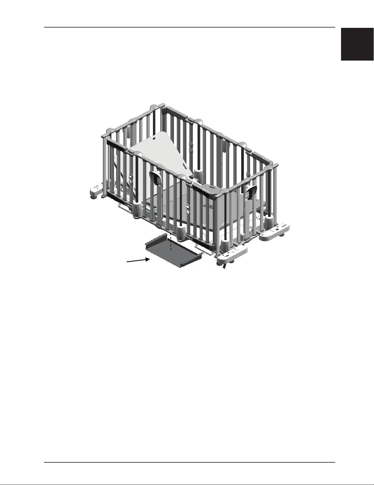
CHART HOLDER / MONITOR HOLDER USAGE (OPTIONAL)
The chart holder (2 1/2 in. high) and the monitor holder (4 1/2 in. high), located under the litter on either or both sides
of the stretcher, are convenient devices allowing the patient’s medical records to follow when the patient is transferred
from one care unit to another or a monitor to be placed on the stretcher.
English
Figure 16 - Chart Holder / Monitor Holder
Return To Table of Contents
www.stryker.com 1900-009-001 REV B 1-27
Page 30
Accessories
English
RETRACTING PROTECTIVE TOP INSTALLATION (FA64074-BIL)
The protective top was designed to close all possible openings about the safety rails.
WARNING
• Remove the patient from the bed before installing the accessory.
• If the stretcher on which the protective top will be installed is equipped with the Weigh system optional), ensure
you turn it off before undertaking the installation of the top. Once done with the installation, refer to the stretcher
Operations Manual to zero the scale.
Necessary Tools:
• 9/16 in. Wrench
Prodedure: (See figure 17)
Note: Two people are necessary to install the protective top.
1. Mount the four posts into the two top plastic structures the following way: Press on the lock pin located on the top
part of the post and insert the post into one of the four slots provided on the plastic structures.
2. Ensure that the post is securely locked in place by checking that the lock pin is positioned in the slot provided on
the outer side of the plastic structure.
3. Install the four posts in the accessory bracket sockets and lock the posts in place using the four hitch pins.
WARNING
It is very important for the patient’s safety that the whole assembly is thoroughly inspected before use to ensure it is
properly and securely mounted.
Protective top
Lower rail
Release knobs
Accessory bracket
Plastic structure
Post
Pin
Figure 17
Return To Table of Contents
1-28 1900-009-001 REV B www.stryker.com
Page 31

Accessories
RETRACTING PROTECTIVE TOP OPERATIONS (FA64074-BIL)
1. To open the protective top from the left or right side of the stretcher, squeeze the two release knobs located on the
lower rail (see figure 18), lift the rail and fold the top toward the opposite side until the desired opening is reached.
2. To close the protective top, grasp the lower rail and lower it until it locks into position. Verify that both lower rail
spring plungers are properly engaged in the slot provided on the plastic structures.
English
Figure 18
WARNING
• For the patient’s safety, ensure that both sides of the two lower rails are properly locked into position before leaving
the patient unattended.
• To avoid injury to the hands and/or fingers, do not use the lateral arms to close the top. Always use the centre of
the lower rail.
CAUTION
Do not use the protective top as a push/pull device.
RETRACTING PROTECTIVE TOP CLEANING
The plastic membrane of the protective top may be clean daily with mild soaps or low concentrated ammonia based
cleaners like window cleaners.
Return To Table of Contents
www.stryker.com 1900-009-001 REV B 1-29
Page 32

Accessories
English
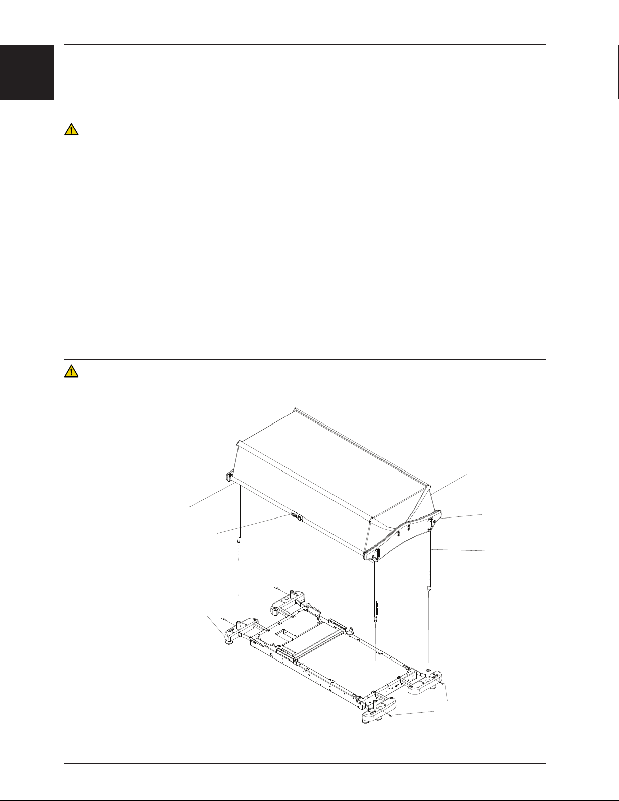
PROTECTIVE TOP WITH SUPPORTS INSTALLATION (FA64183-BIL)
The protective top was designed to close all possible openings about the safety rails.
WARNING
• Remove the patient from the bed before installing the accessory.
• If the stretcher on which the protective top will be installed is equipped with the Weigh system optional), ensure
you turn it off before undertaking the installation of the top. Once done with the installation, refer to the stretcher
Operations Manual to zero the scale.
Necessary Tools:
• 9/16 in. Wrench
Prodedure: (See figure 19)
Note: Two people are necessary to install the protective top.
1. Mount the four posts
into the two top plastic
structures the following
way: Press on the lock
pin located on the top
part of the post and insert
the post into one of the
four slots provided on the
plastic structures.
2. Ensure that the post is
securely locked in place
by checking that the lock
pin is positioned in the slot
provided on the outer side
of the plastic structure.
3. Install the four posts in the
accessory bracket sockets
and lock the posts in place
using the four hitch pins.
WARNING
LOWER RAIL
RELEASE
KNOBS
POSITIONING FRAME
ANCHOR
POINTS
It is very important for the
patient’s safety that the
whole assembly is thoroughly
POST
PLASTIC
STRUCTURE
inspected before use to ensure
it is properly and securely
mounted.
ACCESSORY
BRACKETS
PINS
Figure 19
Return To Table of Contents
1-30 1900-009-001 REV B www.stryker.com
Page 33
Accessories
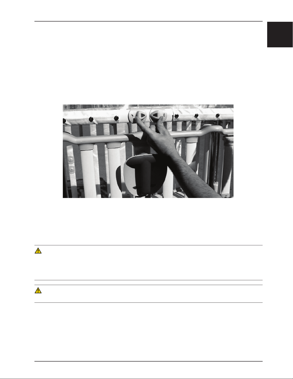
PROTECTIVE TOP WITH SUPPORTS OPERATIONS (FA64183-BIL)
Note: Unless indicated otherwise, the items mentioned and underlined in this operation procedure refer to figure 19.
1. To partially open the protective top, squeeze the two release knobs (Figure 20), lift the lower rail until the anchor
points are slightly passed, release the knobs and bring the rail back so its ends rest in the anchor points.
Note: Ensure that the lower rail ends are properly positioned in the anchor points by trying to lower the rail without
activating the release knobs.
2. To completely open the protective top, unlock the lower rail by squeezing the release knobs, and, while maintaining
them squeezed, lift the rail until the maximum opening of the top is reached. Release the knobs when the anchor
points are passed.
English
Figure 20
3. To close a partially opened top, slightly lift the lower rail to remove it ends from the anchor points, then squeeze
the release knobs and bring the rail back to its original position. Release the knobs.
4. To close a completely opened top, grasp the lower rail, squeeze the release knobs and bring the rail back to its
original position. Release the knobs.
WARNING
• Before leaving the patient unattended after closing the protective top, ensure that both sides of the two lower rails
are properly locked into position.
• To avoid injury to the hands and/or fingers, do not use the lateral arms to close the top. Always use the centre of
the lower rail.
CAUTION
Do not use the protective top as a push/pull device.
PROTECTIVE TOP WITH SUPPORTS CLEANING
The plastic membrane of the protective top may be clean daily with mild soaps or low concentrated ammonia based
cleaners like window cleaners.
Return To Table of Contents
www.stryker.com 1900-009-001 REV B 1-31
Page 34

Cleaning
English
These instructions are intended to provide recommended cleaning methods for stretcher mattresses. They outline
proper care that will provide effective cleaning and disinfecting of mattresses between patients and prolong the life of
the mattress.
RECOMMENDED CLEANING METHOD
• Hand-wash all surfaces of the mattress with warm water and mild detergent cleaner.
• Dry thoroughly.
• Apply disinfectant solution either by spray, solution or pre-impregnated wipes (do not soak mattress).
• Clean per hospital protocol for bed mattresses.
• Wipe up excess disinfectant.
• Rinse with clean water.
• Allow surface to dry.
RECOMMENDED DISINFECTANTS
IMPORTANT: DILUTE ALL DISINFECTANTS IN ACCORDANCE WITH MANUFACTURER’S DIRECTIONS
When used in concentrations recommended by the manufacturer, diluted bleach, diluted phenolic, or diluted quaternary
germicidal disinfectants are recommended.
Chlorine Bleach, typically 5.25% Sodium Hypochlorite, should be used at a dilution ratio of 1 part bleach to 10 parts
water.
RINSE OFF CORROSIVE CLEANERS
These products are NOT considered mild detergents. They are corrosive in nature and may cause damage to your
stretcher mattress if used improperly. Mattresses must be rinsed with clean water and dried thoroughly after using
corrosives such as quaternary, phenolic, or chlorine bleach. Failure to properly rinse and dry the mattress leaves a
corrosive residue on the surface, likely causing premature corrosion.
Iodophor type disinfectants are not recommended for use because staining may result.
The following table lists the recommended cleaner types for each mattress cover material (see definitions below):
Vinyl Mattress Cover Polyurethane Mattress Cover
Recommended Phenolics Quaternary, Quat/Isopropyl
Acceptable Quaternary, Chlorine Bleach (1:10) Chlorine Bleach (1:10)
Not Recommended Quat/Isopropyl Phenolics
Quaternary Cleaners: identified by ingredients containing the phrase “…yl ammonium chloride”
Quat/Isopropyl Cleaners: identified by a quaternary ingredient above plus isopropyl alcohol
Phenolic Cleaners: identified by ingredients containing the suffix “-phenol”
Chlorine Bleach: known generically as “Sodium Hypochlorite
Return To Table of Contents
1-32 1900-009-001 REV B www.stryker.com
Page 35

Cleaning
SPECIAL INSTRUCTIONS
Velcro: to clean and disinfect Velcro, saturate with disinfectant, rinse with water, and allow it to evaporate.
Soils or Stains: use neutral soaps and warm water. Do not use harsh cleansers, solvents or abrasive cleaners.
Hard-To-Clean Spots: use standard household/vinyl cleansers and a soft bristle brush on troublesome spots or stains.
Pre-soak heavy, dried-on soil.
Laundering is NOT RECOMMENDED: laundering may substantially decrease the useful life of the mattress.
DO NOT STEAM CLEAN, PRESSURE WASH, HOSE OFF OR ULTRASONICALLY CLEAN MATTRESSES.
Using these methods of cleaning is not recommended and may void this product’s warranty.
REMOVAL OF IODINE STAINS
1. Make a solution of 1−2 tablespoons Sodium Thiosulfate in a pint of warm water and use it to wipe the stained area.
Clean the stain as soon as possible after it occurs. If stains are not immediately removed, allow solution to soak
or stand on the surface before wiping.
2. Rinse surfaces which have been exposed to the solution with clear water before returning mattress to service.
NOTE
Failure to follow the above directions when using these types of cleaners may void this product’s warranty.
English
Return To Table of Contents
www.stryker.com 1900-009-001 REV B 1-33
Page 36

Preventive Maintenance
English
Remove product from service before you perform the preventive maintenance inspection. At a minimum, check all items
listed during annual preventive maintenance for all Stryker Medical products. You may need to perform preventive
maintenance checks more frequently based on your level of product usage. Service only by qualified personnel.
CHECKLIST
____ All fasteners secure.
____ No cables worn, pinched, or frayed.
____ Replace siderail assist cable every five years.
____ Replace siderail central column spring every four years.
____ All plastic covers (including the base hood) intact. Replace if broken. Patient’s safety could be at stake if any
plastic cover is cracked, as sharp edges may be present.
____ Lubricate where required (see Maintenance Manual, figure 2.2, page 12).
____ Calibrate the scale (optional) once a year.
____ Review each function of the (optional) scale. Refer to the verification of the scale in the Setup Procedure
section (page 8). If the weight calibrated is out of the acceptable range (± 0.5 lb (0.2 kg) at 50 lb (22 kg) or
less or ± 1.0 lb (0.4 kg) at ≥ 50 lb (22 kg) when flat), immediately recalibrate the scale system (see section 3.7
of the Maintenance Manual, “Scale Calibration”).
____ Side/endrail handles trigger and rotating movement operates properly.
____ Side/endrails raise and lower smoothly, and lock in the 9 in., 14 in. and upper positions. If a siderail moves with
difficulty, remove the brake shoe cover and adjust the position of the stop catches. Refer to step 11 of the
“Central Column Assembly” replacement procedure, page 34 of the Maintenance Manual.
____ Side/endrails automatically stop at the 9 in. position when lowered without interruption (handle kept rotated to
the left or right while lowering the rail) from upper positions. Rotating the handle to the left or right further
lowers the rail from the 9 in. position to its lowest position under the mattress surface.
NOTE: On some stretchers, the 9 in. double safety lock may not be present.
____ Optional access doors open, close and lock properly. Release knobs operate properly.
____ Check the optional access door open/close color indicators for proper operation. Green should appear when
the door is closed and locked, and yellow when the door is open. Verify the access doors are closed and
locked when both open/close indicators show green.
____ Optional assisted or manual Fowler operates properly.
____ Foot section support arm operates properly.
____ Optional brake pedal operates properly. All casters lock with the brake pedal engaged.
____ Optional steer pedal operates properly. Fifth steer wheel operational with the steer pedal engaged.
____ Optional lift pedal operates properly. Litter raises when the pedal is pumped.
____ Optional uni-lower pedal operates properly. Trendelenburg positions and litter descent are operational when
uni-lower pedal is depressed.
____ All casters secure and swivel properly. Ground chain secured to frame and intact.
____ Fixed height stretcher four casters lock and unlock properly using the brake lever.
____ No oil leak on optional hydraulic jacks.
____ Optional hydraulic jacks holding properly.
____ Optional hydraulic jack oil level sufficient (see Maintenance Manual, section 3.2).
____ No rips or cracks in the mattress cover.
____ Optional retracting protective top secure and working properly.
____ Optional IV Caddy secure and working properly.
____ Standard or optional premium accessory brackets secure.
Product serial number:
Completed by: _______________________________________ Date: ___________________
Return To Table of Contents
1-34 1900-009-001 REV B www.stryker.com
Page 37

Recycling passport
Assembly Part Number: OL190186 (Reference Only)
English
A
B
Item Recycling/Material Code Important Information Qty
A (QDF19-0888) Circuit Board 1
B (QDF7909) C Battery 4
Return To Table of Contents
www.stryker.com 1900-009-001 REV B 1-35
Page 38

Warranty
English
LIMITED WARRANTY
Stryker Medical Division, a division of Stryker Corporation, warrants to the original purchaser the Cub® Pediatric
Stretcher to be free from defects in material and workmanship for a period of one (1) years after date of delivery.
Stryker’s obligation under this warranty is expressly limited to supplying replacement parts and labor for, or replacing,
at its option, any product which is, in the sole discretion of Stryker, found to be defective. If requested by Stryker,
products or parts for which a warranty claim is made shall be returned prepaid to the factory. Any improper use or
any alteration or repair by others in such manner as in Stryker’s judgment affects the product materially and adversely
shall void this warranty. Any repair of Stryker products using parts not provided or authorized by Stryker shall void this
warranty. No employee or representative of Stryker is authorized to change this warranty in any way.
Stryker Medical Stretcher products are designed for a 10 year expected service life under normal use, conditions, and
with appropriate periodic maintenance as described in the maintenance manual for each device. Stryker warrants to
the original purchaser that the welds on its Stretcher products will be free from structural defects for the expected 10
year life of the Stretcher product as long as the original purchaser owns the product.
WARRANTY EXCLUSION AND DAMAGE LIMITATIONS
The express warranty set forth herein is the only warranty applicable to the product. Any and all other warranties,
whether express or implied, including any implied warranty of merchantability or fitness for a particular purpose
are expressly excluded by Stryker. In no event shall Stryker be liable for incidental or consequential damages.
TO OBTAIN PARTS AND SERVICE
Stryker products are supported by a nationwide network of dedicated Stryker Field Service Representatives. These
representatives are factory trained, available locally, and carry a substantial spare parts inventory to minimize repair
time. Simply call your local representative or call Stryker Customer Service at 1-800-327-0770.
RETURN AUTHORIZATION
Product cannot be returned without prior approval from the Stryker Customer Service Department. An authorization
number will be provided which must be printed on the returned product. Stryker reserves the right to charge shipping
and restocking fees on returned product. Special, modified, or discontinued products are not subject to return.
DAMAGED MERCHANDISE
ICC Regulations require that claims for damaged product must be made with within fifteen (15) days of receipt of the
product. Do not accept damaged shipments unless such damage is noted on the delivery receipt at the time of receipt.
Upon prompt notification, Stryker will file a freight claim with the appropriate carrier for damages incurred. Claims will
be limited in amount to the actual replacement cost. In the event that this information is not received by Stryker within
the fifteen (15) day period following the delivery of the product, or the damage was not noted on the delivery receipt at
the time of receipt, the customer will be responsible for payment of the original invoice in full within thirty (30) days of
receipt. Claims for any incomplete shipments must be made within thirty (30) days of invoice.
INTERNATIONAL WARRANTY CLAUSE
This warranty reflects U.S. domestic policy. Warranty outside the U.S. may vary by country. Contact your local Stryker
Medical representative for additional information.
Return To Table of Contents
1-36 1900-009-001 REV B www.stryker.com
Page 39

Page 40
CUB Crib - Model FL19
D
C
E
A
B
F
Scale Operation
The scale system allows the reading of a patient’s weight in pounds (lb) or kilograms (kg) within ± 0.5 lb (0.2 kg) at 50
lb (22 kg) or less and within ± 1.0 lb (0.4 kg) at ≥ 50 lb (22 kg) when flat. The reading can be stored in memory. The
system also allows to add or remove a device or accessory from the stretcher without removing the patient.
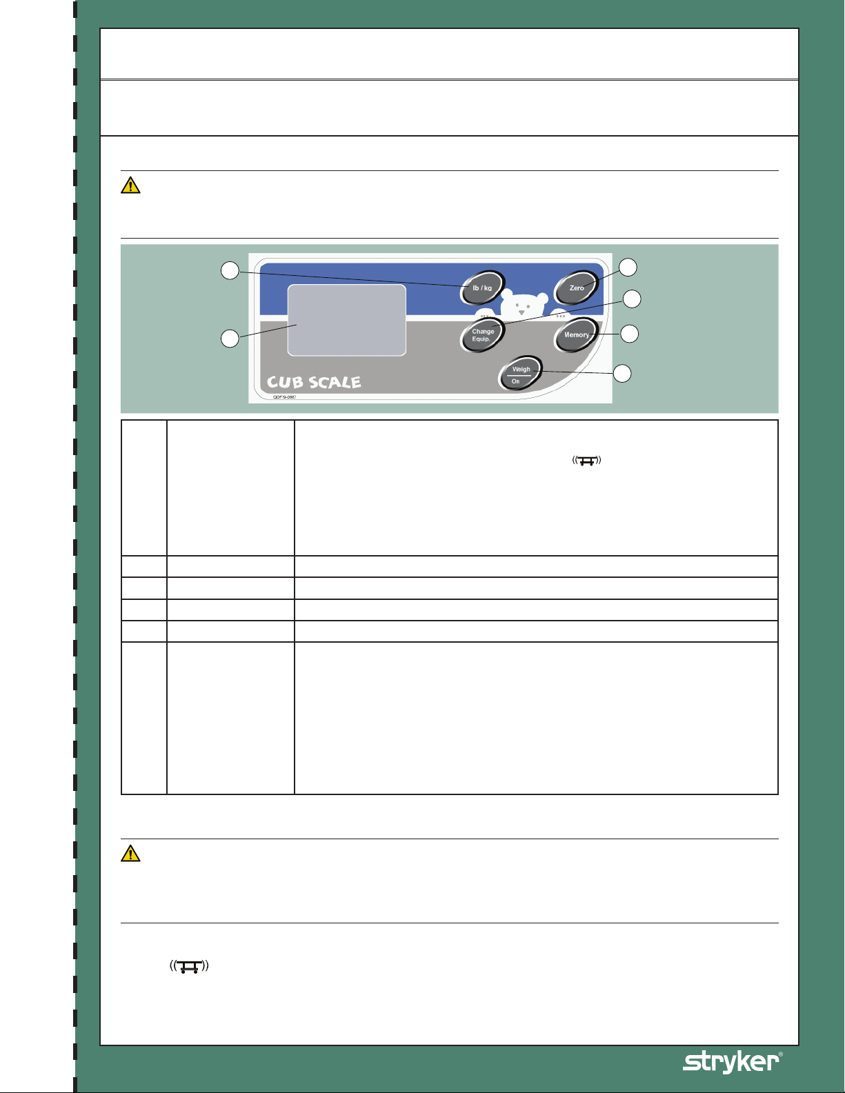
SCALE CONTROL PANEL
CAUTION
• To avoid damage to the scale electronic components, do not lean on the accessory bracket housing the scale module.
• Do not use a two or three stage fixed IV pole at the foot end of a stretcher equipped with the scale.
Weigh/On
A
Memory Stores the result of the weighing or recalls on display the weight stored.
B
Zero Zeroes the weight displayed on screen and the weight stored.
C
lb / kg Changes the unit of measurement (lb or kg).
D
Change Equipment To remove or add equipment from the stretcher without removing the patient.
E
Scale Display
F
SCALE OPERATION
Activates the scale. A weighing is performed when this button is pressed and released.
A weight will be displayed on the display four to ten seconds later. However, no weight
is displayed if the Error -Ex.x or the movement
error will have to be corrected or the stretcher stabilized before using the scale again
(see the Error Code List in the Maintenance Manual).
NOTE
The scale does not work in continuous mode. It must be activated using the Weigh/
On key each time a reading of the patient’s weight is required.
The scale will auto shut off after an inactivity period of 30 seconds, except during the
Change Equipment operation where three minutes are allowed. Press the Weigh/On
button to reactivate the scale.
If the patient weighs more than 100 lb (54 kg), the “Error - E05” message will appear
on the display to indicate that the scale should not be used in these conditions, as its
maximal weighing capacity is exceeded.
Some other error messages may be displayed while operating the scale. Refer to the
Error Code List in the Maintenance Manual to understand their signification and what
action to take when they appear.
icon appears on display. The
CUB Crib Quick Reference Guide
CAUTION
Detach Here Detach Here
The scale weighing zone is made up of all the upper part of the stretcher, including the safety end/siderails, the accessory
brackets, the drainage bag hooks, the chart and monitor holders (optional) located under the mattress support. Ensure
no external object is in contact with the stretcher during a weighing or when zeroing the scale.
NOTE
• The
• The Memory, Change Equipment and Zero keys may be used to stop the weight reading process when the operation currently
Part Number: 1900-069-001 Rev A.0
Refer to the operations manual for additional information.
icon may appear at any time when using the scale. It indicates that the scale is unable to take a reading of the
patient’s weight because the stretcher is unstable. Simply stabilize the stretcher and repeat the current operation.
used does not need a weight reading to be displayed.
Page 41

CUB Crib - Model FL19
Scale Operation (Continued)
SCALE OPERATION (CONTINUED)
A. PREPARING (ZEROING) THE SCALE FOR A NEW PATIENT
• Prepare the stretcher for the new patient (sheets, pillows, equipment, etc.).
• Press and release the Weigh/On button to activate the scale. A weight reading will appear on the display four to ten
seconds later during which a three-hyphen line will flash.
• Press and keep pressed the Zero button during at least two seconds. Release the key; the weight displayed and the
weight stored will be zeroed four to ten seconds later.
• With the patient in the stretcher, press the Weigh/On button. The patient’s weight will be displayed four to ten
seconds later.
CAUTION
To maintain the scale accuracy, it is recommended to zero the scale at least once a week. Note that the patient must be
removed from the stretcher before zeroing the scale.
B. STORING IN MEMORY A WEIGHT READING
• Press the Weigh/On button to activate the scale. Wait for the reading to be displayed.
• Press and hold the Memory button for two seconds. Release the button when the “Memory” message appears on
the display. The weight previously displayed is now stored.
Detach Here Detach Here
C. RECALLING ON DISPLAY THE WEIGHT STORED IN MEMORY
• Press the Weigh/On button to activate the scale. Do not wait for the weight to be displayed, proceed immediately
with the next step.
• Press the Memory button. The value stored will be displayed along with “Memory”. To leave the Memory mode, press
the Weigh/On button.
D. ZEROING THE WEIGHT DISPLAYED AND STORED IN MEMORY
• Press the Weigh/On key to activate the scale. Do not wait for the weight to be displayed, proceed immediately with
the next step.
• Press and hold the Zero button for at least two seconds. Release the button; the weight displayed and the weight
stored will be zeroed four to ten seconds later.
E. ZEROING THE MEMORY ONLY
• Press the Weigh/On button to activate the scale. Do not wait for the weight to be displayed, proceed immediately
with the next step.
• Simultaneously press and hold the Memory and Zero buttons for at least two seconds and release. The screen will
display 0.0 lb/kg.
F. ADDING OR REMOVING EQUIPMENT WITH A PATIENT IN THE STRETCHER
• Press the Weigh/On button to activate the scale. You may proceed immediately with the next step, but if you want to
CUB Crib Quick Reference Guide
compare the weight reading resulting from the Change Equipment procedure with the patient’s weight reading before
the procedure, let the weigh process display a weight reading and note the weight.
• Press the Change Equipment button. The “Change Equipment” message will appear on the display four to ten
seconds later. NOTE: the scale will automatically shut off if this step takes more than three minutes. The operation
will then have to be started over.
• Add or remove the equipment on the stretcher. Then, press the Change Equipment button. The unchanged patient’s
weight will reappear on the screen four to ten seconds later.
NOTE
To prevent erroneous weight readings, the “Adding or Removing Equipment with a Patient in the Stretcher” procedure must be
completed each time an object is added or removed from the scale weighing zone.
G. CHANGING THE UNIT OF MEASUREMENT
• Press the Weigh/On button to activate the scale. A weight reading will appear on the display four to ten seconds later.
• Press the lb /kg button to change from pounds (lb) to kilograms (kg) or conversely.
• The lb /kg button can be deactivated to prevent inadvertent use of the button. To do so, press and hold the lb /kg
and Memory buttons for at least two seconds. Do the same to reactivate the lb /kg button.
Part Number: 1900-069-001 Rev A.0
Refer to the operations manual for additional information.
Page 42
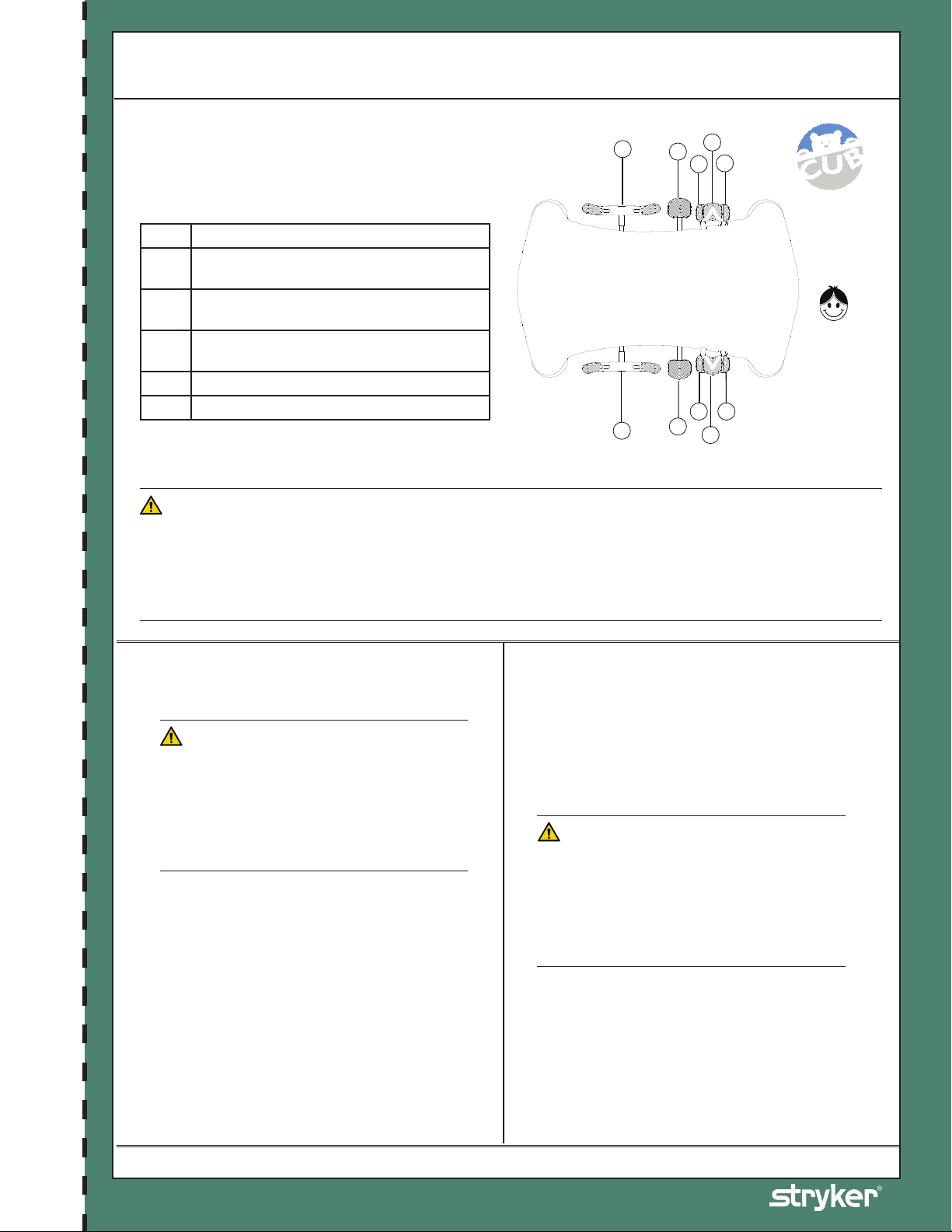
BASE CONTROLS
E
F
A
A
D B C
D
B
C
CUB Crib - Model FL19
Features Overview
Two types of base models are available: the Fixed Height
and Variable Height (hydraulic).
Pump to raise litter.
A
Depress the center of pedal (B) to lower both
B
ends of the stretcher together.
Depress the side of pedal (B) closest to the
C
stretcher head end to lower the head end.
Depress the side of pedal (B) closest to the
D
stretcher foot end to lower the foot end.
Brake and Steer functions (left side) Steer.
E
Steer and Brake functions (right side).
F
APPLYING THE BRAKES
RIGHT
HEAD END
LEFT
Base Controls
WARNING
• Always apply the brakes when a patient is removed from or placed on the stretcher.
• Always engage the brakes unless the stretcher is being moved. Push on the stretcher to ensure the brakes are
securely locked.
• Serious injury could result if a stretcher moves while a patient is placed or removed from the stretcher.
• If brakes do not hold properly, refer to your stretcher maintenance manual for the brake adjustment procedure.
Detach Here Detach Here
RAISING / LOWERING LITTER (OPTIONAL)
- FL19H ONLY
WARNING
To avoid injury to the patient and/or the user,
ensure the rails are in their highest position
before lowering the litter or placing it in one of the
Trendelenburg positions, and that all equipment
and people are removed from the area below and
around the litter.
Be sure to move any equipment that may be in
the way before raising or lowering the litter.
• To raise the litter height, pump pedal
(A) repeatedly until the desired height is
achieved.
• To lower both ends of the litter together,
depress the center of pedal (B) until the
desired height is achieved. To lower only the
head end of the litter, depress the side of
pedal (B) closest to the head end. To lower
only the foot end of the litter, depress the
side of pedal (B) closest to the foot end.
TRENDELENBURG / REVERSE
TRENDELENBURG (OPTIONAL)
- FL19H ONLY
NOTE
The litter height must be raised first in order to
achieve a Trendelenburg position.
WARNING
To avoid injury to the patient and/or the user,
ensure the rails are in their highest position
before lowering the litter or placing it in one of the
Trendelenburg positions, and that all equipment
and people are removed from the area below and
around the litter.
• For Trendelenburg positioning (head down),
depress the side of pedal (B) closest to the
stretcher head end.
• For Reverse Trendelenburg positioning (foot
down), depress the side of pedal (B) closest
to the stretcher foot end.
CUB Crib Quick Reference Guide
Part Number: 1900-069-001 Rev A.0
Refer to the operations manual for additional information.
Page 43
CUB Crib - Model FL19
Warnings and Cautions
WARNING
• Hospital staff should ensure a safe environment to the patient by verifying that the stretcher components (rails, access doors, accessories,
etc.) are in good condition and properly secured before placing a patient on the stretcher.
• Always apply the brakes when a patient is removed from or placed on the stretcher. Always engage the brakes unless the stretcher is
being moved. Push on the stretcher to ensure the brakes are securely locked. Injury could result if a stretcher moves while a patient is
placed or removed from the stretcher.
• When brakes are applied on a fixed height stretcher, be sure all four casters are locked to ensure a complete immobilization of the
stretcher.
• To reduce risk of injury, ensure the litter is horizontal and in the lowest position with the rails fully raised when moving the pediatric
stretcher with a patient on it.
• The rails must always remain in the highest position and the litter in the lowest position unless the patient is being tended. Never leave a
patient unattended when the rails are lowered.
• Make sure that proper policies are applied to ensure the patient’s safety when an IV pole and/or an oxygen bottle is used. The patient
should not be able to reach nor manipulate them.
• To prevent possible fire hazard when using an oxygen tent on a stretcher equipped with the scale system (optional), do not activate the
scale. Also ensure that the rails are outside the tent.
• To avoid injury to the patient and/or the user, ensure the rails are in their highest position before lowering the litter or placing it in one of
the Trendelenburg positions, and that all equipment and people are removed from the area below and around the litter.
• To avoid falls and injury, verify the rails and access doors are properly locked into position before leaving a patient unattended or after
having moved a rail or an access door.
• To avoid injury to the patient, ensure the patient’s extremities are clear of all moving parts before operating a rail. Always ensure the rail
is securely locked after moving it.
• To avoid falls and injury, ensure that both access door open/close indicators (located on both lock release knobs) show green when the
door is closed and locked into position.
• Avoid using an access door or a rail handle as push/pull devices or damage to the unit or injury to the patient and/or user may occur.
• To avoid injury to the patient and/or user, do not attempt to move the stretcher directly sideways with the steer mode engaged. The fifth
steer wheel cannot pivot.
• To avoid injury to the patient, verify the patient is safely positioned on the litter before lowering the siderail or operating the Fowler or
foot section.
• To avoid injury to the patient when raising or lowering the manual Fowler or the foot section, verify the support arm is securely engaged
in the arm stoppers before releasing the Fowler or foot section.
• When patient is able to climb out the stretcher or reaches the height of 35 in. (90 cm), the stretcher shall no longer be used.
• Do not place cords, straps or similar items that could become wound around the patient’s neck in or near the stretcher.
• Do not leave objects or toys in the stretcher.
• Do not use a water mattress with this stretcher.
• To avoid injury to the patient, any mattress used on this stretcher must be at least 57 1/2 in. (146.05 cm) long by 29 3/8 in. (74.6 cm) wide
and not less than 3 in. (7.6 cm) or more than 6 in. (15.3 cm) thick.
• Failure to properly clean the mattress, or dispose of it if defective, may increase the risk of exposure to pathogenic substances and may
bring about diseases to the patient and/or the user.
• Do not use the stretcher if any components are missing or broken. Contact your dealer or Stryker for replacement parts. Use only
replacement parts provided by Stryker.
• Maximum static weight capacity = 400 lb (181.4 kg).
Detach Here Detach Here
CAUTION
• To avoid damage to the scale electronic components, do not lean on the accessory bracket housing the scale module.
• Do not use a two or three stage fixed IV pole at the foot end of a stretcher equipped with the scale.
• The scale weighing zone is made up of all the upper part of the stretcher, including the safety end/siderails, the accessory brackets, the
CUB Crib Quick Reference Guide
drainage bag hooks, the chart and monitor holders (optional) located under the mattress support. Ensure no external object is in contact
with the stretcher during a weighing or when zeroing the scale.
• To maintain the scale accuracy, it is recommended to zero the scale at least once a week. Note that the patient must be removed from
the stretcher before zeroing the scale.
• Use only 1.5 VDC alkaline batteries. The use of batteries other than the one recommended may damage the scale electronic components.
• Remove the batteries if the scale module or the stretcher is not used for long periods.
• Always store the IV Caddy when not in use to avoid damaging it when the stretcher is moved.
• The weight of the IV bags should not exceed 40 lb (18 kg).
• Do not install a two or three-stage fixed IV pole at the foot end of a stretcher equipped with the scale.
• Do not use the protective top as a push/pull device.
The information presented in this Quick Reference Guide is intended to demonstrate a Stryker product. Always refer to the package insert, product
label and/or Operations manual before using any Stryker product. Products may not be available in all markets. Some features indicated in this Quick
Reference Guide are options and may not be configured on all products. Product availability is subject to the regulatory or medical practices that
govern individual markets. Please contact your Stryker Account Manager if you have questions about the availability of Stryker products in your area.
Products referenced with ™ designation are trademarks of Stryker.
Products referenced with ® designation are registered trademarks of Stryker.
Part Number: 1900-069-001 Rev A.0
Refer to the operations manual for additional information.
Page 44

Civière pédiatrique
voir au dos du manuel
Détachable Guide de référence rapide
CUB
REF
FL19F/H (190)
®
Manuel d’utilisation
2014/10 B.0 1900-009-001 REV B www.stryker.com
Page 45

Page 46

Symboles
Avertissement/Mise en garde, consulter la documentation d’accompagnement
Charge maximale admissible
Appareil du type BF
Appareil à source électrique interne alimenté par batteries
IPX4
REF
Protection contre les projections de liquides
Courant direct
Conformément à la directive européenne 2002/96/EC sur les rebuts d’équipements électriques et
électroniques, ce symbole indique que le produit ne doit pas être disposé comme un rebut municipal non
trié, mais devrait être recueilli séparément. Référez-vous à votre distributeur régional pour le retour et/ou
les systèmes de collection disponibles dans votre pays.
,NCKD
Fabricant
Page 47

Page 48

Table des matières
Symboles ................................................................................1
Introduction ............................................................................2-4
Utilisation prévue .....................................................................2-4
Renseignements techniques.............................................................2-5
Conditions d’environnement .............................................................2-6
Illustration du produit ..................................................................2-7
Informations de contact ................................................................2-8
Résumé des mesures de sécurité ............................................................2-9
Vérification des côtés (s’applique aux côtes mobiles) .........................................2-11
Vérification des portes d’accès (s’applique aux portes d’accès mobiles) ........................... 2-11
Vérification de la balance (en option) .....................................................2-11
Vérification des commandes de la base ....................................................2 -12
Vérification de la mobilité des sections du sommier............................................2-12
Autres .............................................................................2-12
Fonctionnement .........................................................................2-13
Commandes de la base ................................................................2 -13
Fonctionnement des freins ..............................................................2 -14
Fonctionnement de la 5e roue directionnelle (en option) ........................................2 -14
Élévation / descente du sommier (en option) - FL19H seulement ..................................2 -15
Trendelenburg / Trendelenburg inversé (en option) - FL19H seulement..............................2 -15
Positionner les sections de tête et de pied ................................................. 2 -16
Positionner la section de tête manuelle.................................................... 2 -16
Positionner la section de tête assistée par pneumatique ....................................... 2 -16
Positionner la section de pied .......................................................... 2-1 6
Fonctionnement des côtés de sûreté ......................................................2 -17
Fonctionnement des portes d’accès (en option) ..............................................2 -17
Fonctionnement de la balance (en option) ..................................................2 -18
Remplacement des batteries ...........................................................2-20
Accessoires ...........................................................................2-21
Utilisation du support d’accessoires régulier ................................................2-21
Utilisation du support d’accessoires de luxe (en option)........................................2-21
Utilisation du collet pour bouteille d’oxygène (en option) .......................................2-22
Fonctionnement du bras d’attache (en option)...............................................2-22
Fonctionnement de la tige à soluté fixe à deux étages (en option)................................2-23
Fonctionnement de la tige à soluté à trois étages (en option) ...................................2-24
Utilisation du support à dossier / porte-moniteur (en option) ....................................2-25
Toit de protection d’installation (FA64074-BIL)...............................................2-26
Toit de protection avec supports d’installation (FA64183-BIL)....................................2-28
Nettoyage.............................................................................2-30
Méthode de nettoyage recommandée.....................................................2-30
Désinfectants recommandés ...........................................................2-30
NETTOYANTS CORROSIFS À RINCER.................................................... 2-30
Directives particulières................................................................ 2-31
ÉLIMINATION DES TACHES D’IODE ......................................................2-31
Français
www.stryker.com 1900-009-001 REV B 2-1
Page 49

Français
Table des matières
Entretien préventif ......................................................................2-32
Liste de vérification ..................................................................2-32
Recyclabilité...........................................................................2-33
Garantie..............................................................................2-34
Garantie limitée .....................................................................2-34
Exclusion de garantie et limitations des dommages...........................................2-34
Pièces de rechange et service technique ..................................................2-34
Autorisation de retour.................................................................2-34
Produit endommagé..................................................................2-34
Clause de garantie internationale ........................................................2-35
Guide de référence du lit CUB Crib.......................................................... 2-37
Commandes de la base ...............................................................2-39
Fonctionnement des freins ............................................................. 2-39
Élévation / descente du sommier
(en option) - FL19H seulement.......................................................... 2-39
Trendelenburg / Trendelenburg inversé
(en option) - FL19H seulement.......................................................... 2-39
2-2 1900-009-001 REV B www.stryker.com
Page 50

Définition de « Avertissement », « Mise en garde » et « Remarque »
Les rubriques Avertissement, Mise en garde et Remarque ont une signification particulière et doivent faire l’objet
d’une lecture attentive.
AVERTISSEMENT
Avertit le lecteur des précautions à prendre afin d’éviter une situation présentant un risque potentiel de décès ou de blessure grave.
Peut également attirer l’attention sur l’existence potentielle d’effets indésirables graves ou de risques d’accident.
MISE EN GARDE
Avertit le lecteur des mesures à prendre afin d’éviter une situation potentiellement dangereuse susceptible de causer des blessures
mineures ou modérées à l’utilisateur ou au patient ou d’endommager le matériel en question ou d’autres biens. Couvre notamment les
précautions à prendre afin d’assurer l’utilisation sécuritaire et efficace du matériel et d’éviter les dommages qui pourraient découler
de l’utilisation ou d’une utilisation inappropriée du matériel.
Remarque
Il s’agit de renseignements spécifiques destinés à faciliter l’entretien ou à clarifier des instructions importantes.
Français
Retour à la table des matières
www.stryker.com 1900-009-001 REV B 2- 3
Page 51

Français
Introduction
UTILISATION PRÉVUE
Ce guide a été conçu pour vous aider dans l’utilisation de la civière pédiatrique CUB® modèle FL19 de Stryker.
Afin d’assurer un environnement sécuritaire aux patients, il est extrêmement important que ce guide soit lu et que
les informations qu’il contient soient bien comprises avant d’utiliser la civière. Ce guide doit être à la disposition du
personnel soignant afin qu’il puisse s’y référer en tout temps.
Ce guide de l’utilisateur fait partie intégrante de la civière et doit donc être remis à son nouveau propriétaire dans le
cas d’un transfert ou d’une vente.
BRÈVE DESCRIPTION DU PRODUIT ET DÉCLARATION D’UTILISATION PRÉVUE
INDICATIONS MÉDICALES PRÉVUES: Le lit pédiatrique Stryker Cub est un lit d’hôpital/brancard à usage médical
qui se compose d’un lit ou berceau conçu pour un enfant, il est doté de barreaux fixes aux extrémités et de barreaux
latéraux amovibles et verrouillables. Le contour de la surface du lit peut être réglable.
POPULATION DE PATIENTS PRÉVUE: La charge maximale admissible fait référence au poids total du patient, du
matelas et des accessoires. La charge maximale admissible pour le lit pédiatrique Stryker Cub est de 45 kg. Ce lit n’est
pas conçu pour une utilisation avec un patient dont la taille est supérieure à 89 cm.
PARTIE DU CORPS PRÉVUE: Le lit pédiatrique Stryker Cub est conçu pour prendre en charge un patient conformément
aux charges maximales admissibles prévues. Le patient peut entrer en contact avec le lit mais ne doit jamais être placé
sur la structure sans surface de couchage. Le lit pédiatrique Stryker Cub est conçu pour être utilisé avec une surface
de couchage de 10 cm d’épaisseur, une surface de couchage plus épaisse ou un revêtement à valeur thérapeutique.
Le lit doit être utilisé avec une extrême précaution. La supervision du patient est suggérée.
PROFIL DE L’UTILISATEUR PRÉVU: Le lit pédiatrique Stryker Cub est destiné aux patients en centre de soins intensifs,
y compris aux services des urgences, sous traitement dégressif, en soins progressifs, en soins médico-chirurgicaux, en
soins subaigus et en salle de surveillance post-interventionnelle (SSPI) ou dans tout autre établissement professionnel
de santé, selon la prescription d’un professionnel de la santé. Le lit pédiatrique Stryker Cub n’est pas prévu pour être
utilisé dans le cadre de soins à domicile. L’opérateur type du lit pédiatrique Stryker Cub est un professionnel de la
santé expérimenté.
CONDITIONS D’UTILISATION ET DURÉE DE VIE PRÉVUES: Le lit pédiatrique Stryker Cub est conçu pour une durée
de vie utile prévue de 10 ans dans des conditions normales d’utilisation et avec un entretien périodique approprié
comme décrit dans le manuel d’entretien de chaque dispositif. Stryker garantit à l’acheteur initial que les soudures
présentes seront exemptes de défauts structurels pendant la durée de vie utile prévue de 10 ans du produit aussi
longtemps que l’acheteur initial est en possession du produit.
Retour à la table des matières
2-4 1900-009-001 REV B www.stryker.com
Page 52

RENSEIGNEMENTS TECHNIQUES
Introduction
Modèle FL19H
190 Base hydraulique
Charge maximale admissible 100 lb (45 kg) 100 lb (45 kg)
Longueur/largeur hors-tout
• Sans supports d’accessoires
• Avec supports d’accessoires
Capacité de charge 400 lb (181 kg) 400 lb (181 kg)
Poids total (sans option) 375 lb (170 kg) 310 lb (140,6 kg)
Hauteur limite (jusqu’au dessus du sommier)
• Haute
• Basse
Positionnement du sommier
• À commande manuelle
• Assisté par pneumatique
• Trendelenburg/Trendelenburg inversé
• Articulation de la section de pied
Espace patient 29,5 po x 57 po (75 x 145 cm) 29,5 po x 57 po (75 x 145 cm)
Diamètre des roulettes 6 po (15 cm) 5 po (13 cm)
Mécanisme de freinage
Capacité Patient pesant 4 lb (1,8 kg) à 100 lb (54,4 kg)
Précision
Balance (en option)
Alimentation
Électrique
Caractéristiques
Électriques
65,5 po x 37 po (166 x 94 cm)
72,25 po x 37,5 po (184 x 95 cm)
40 po (102 cm)
33 po (84 cm)
0° / 25° / 40° / 55°
0° - 50°
+/- 9,5°
0° / 6° / 12°
Freinage à anneaux aux quatre
roulettes
Effectuer une échelle de mesure lorsque l’appareil est à plat:
± 0.5 lb (0.2 kg) at 50 lb (22 kg) or less
± 1.0 lb (0.4 kg) at ≥ 50 lb (22 kg)
Batteries - 4 alcalines, type C, 1,5 Vcc
6 Vcc, 0,15 A
65,5 po x 37 po (166 x 94 cm)
72,25 po x 37,5 po (184 x 95 cm)
33 po (84 cm)
33 po (84 cm)
0° / 25° / 40° / 55°
0° - 50°
0° / 6° / 12° à propulsion manuelle au pied
0° / 6° / 12°
Quatre roulettes de blocage
Modèle FL19F
190 Base à hauteur fixe
Français
Stryker porte un soin particulier à l’amélioration de ses produits et se réserve le droit d’en changer les spécifications
sans préavis.
Conforme aux normes suivantes : CSA C22.2, No. 60601.1; UL2601-1; IEC/EN 60601-1.
Remarque: La Cub ® est approuvé CE seulement sans l’option balance.
Retour à la table des matières
www.stryker.com 1900-009-001 REV B 2- 5
Page 53

Introduction
CONDITIONS D’ENVIRONNEMENT
* Environnement d’utilisation recommandé pour assurer la précision de la balance.
Français
Conditions d’environnement Fonctionnement * Rangement et transport
Température ambiante
Humidité relative
(sans condensation)
Pression atmosphérique
15,5 °C
(60 °F)
0 %
700 hPa
29,1 °C
(85 °F)
-30 °C
(-22 °F)
95 %
0 %
1060 hPa
500 hPa
50 °C
(122 °F)
95 %
1060 hPa
Retour à la table des matières
2-6 1900-009-001 REV B www.stryker.com
Page 54
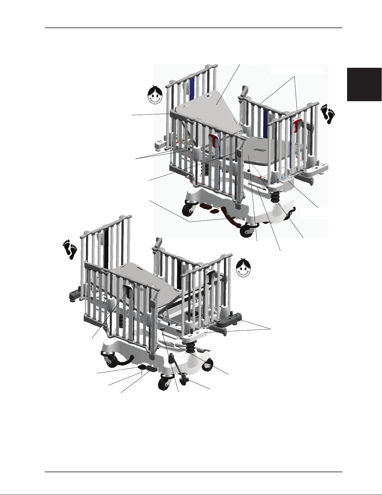
(
)
(
)
(OPTIONAL)
(OPTIONAL)
ILLUSTRATION DU PRODUIT
OPTIONAL ACCESS DOOR
PORTE D’ACCÈS FERMÉE
(EN OPTION)
BOUTONS DE DÉVERROUILLAGE DE LA
ACCESS DOOR RELEASE KNOBS
PORTE D’ACCÈS
(OPTIONAL)
OPTIONAL ACCESS DOOR
PORTE D’ACCÈS OUVERTE
(EN OPTION)
OPTIONAL
PÉDALE DE FREINAGE/
BRAKE / STEER PEDAL
DIRECTION
(OPTIONAL)
(EN OPTION)
Introduction
SECTION DE TÊTE
FOWLER
CÔTÉS DE SÛRETÉ LATÉRAUX
SIDE AND END RAILS
ET D’EXTRÉMITÉ
MODULE BALANCE
SCALE MODULE
(EN OPTION)
OPTIONAL
Français
SIDERAIL ACTIVATION
POIGNÉE D’ACTIVATION
DU CÔTÉ DE SÛRETÉ
HANDLE
LITTER LIFT PEDAL
PÉDALE DE LEVAGE DU
SOMMIER (EN OPTION)
OPTIONAL
(
GROUND CHAIN
CHAÎNE ANTISTATIQUE
)
UNI-LOWER PEDAL
PÉDALE DE DESCENTE (EN
OPTION)
PNEUMATIC HEAD SECTION
LEVIER D’ACTIVATION DE LA
SECTION DE TÊTE ASSISTÉE
ACTIVATION LEVER
SECTION DE PIED
FOOT SECTION
OXYGEN BOTTLE RETAINING COLLAR
BAGUE DE RETENUE POUR BOUTEILLE
D’OXYGÈNE (EN OPTION)
BRAS D’ATTACHE POUR
IV CADDY ARM (OPTIONAL
TIGE À SOLUTÉ MOBILE (EN
OPTION)
CROCHET POUR SAC DE
DRAINAGE BAG HOOK
DRAINAGE
SUPPORTS D’ACCESSOIRES DE
HEAD PREMIUM ACCESSORY
LUXE - TÊTE (EN OPTION)
BRACKETS
)
SUPPORT DE LA SECTION
FOOT SECTION SUPPORT
DE PIED
ARM
(
)
OPTIONAL
Figure 1 - Illustration du lit
Retour à la table des matières
www.stryker.com 1900-009-001 REV B 2-7
Page 55

Introduction
Contacter le service clientèle ou le support technique de Stryker au +1-800-327-0770.
Français
Stryker Medical
3800 E. Centre Avenue
Portage, Michigan 49002
États-Unis
Retour à la table des matières
2-8 1900-009-001 REV B www.stryker.com
Page 56

Résumé des mesures de sécurité
Il est important de lire et de maîtriser le contenu du présent manuel avant d’utiliser la civière pédiatrique Cub®. Lire attentivement et
respecter à la lettre les directives de sécurité indiquées sur la présente page. Les directives de sécurité sont répétées tout au long
du guide, lorsqu’il y a lieu.
AVERTISSEMENT
• Afin d’assurer un environnement sécuritaire au patient, le personnel hospitalier s’assurera que les composants de
la civière (côtés de sûreté, portes d’accès, accessoires, etc.) sont en bon état et fonctionnent correctement avant
d’installer un patient dans la civière.
• Appliquez toujours les freins lorsqu’un patient est retiré ou placé dans la civière.
• Laissez toujours les freins en fonction à moins que la civière ne soit déplacée. Après avoir appliqué les freins,
poussez sur la civière afin de vous assurer qu’elle est bien immobilisée.
• Une civière instable peut causer des blessures graves au patient lorsqu’il est installé sur la civière ou retiré de
celle-ci.
• Si les freins ne fonctionnent pas correctement, référez-vous à la procédure de réglage des freins du manuel
d’entretien.
• Assurez-vous d’appliquer les freins aux quatre roulettes pour une immobilisation complète de la civière à hauteur
fixe.
• Lorsqu’une immobilisation complète de la civière à hauteur fixe est requise, assurez-vous d’activer le mécanisme
de blocage des quatre roulettes de la civière.
• Afin de réduire les risques de blessure, placez le sommier en position horizontale et au plus bas et relevez
complètement les côtés de sûreté lorsqu’un patient est déplacé avec la civière.
• Les côtés de sûreté doivent toujours être maintenus en position haute et le sommier en position basse sauf lorsque
le patient est soigné. Ne laissez jamais un patient sans surveillance lorsque les côtés de sûreté sont abaissés.
• Assurez-vous que des politiques appropriées sont mises en place pour assurer la sécurité du patient lorsqu’une
tige à soluté ou une bouteille d’oxygène est utilisée. Le patient ne doit pas y avoir accès ni les manipuler.
• Afin de prévenir tout risque d’incendie, n’activez pas la balance lorsqu’une tente à oxygène est utilisée sur une
civière munie de la balance (en option). De plus, assurez-vous que les côtés de sûreté sont à l’extérieur de la tente.
• Afin d’éviter les blessures au patient et/ou à l’utilisateur, assurez-vous, avant de baisser le sommier ou de le placer
en l’une des positions Trendelenburg, que les côtés de sûreté sont complètement relevés et qu’aucun équipement
ni personne ne se trouve près du sommier ou sous celle-ci.
• Afin d’éviter les blessures au patient et/ou à l’utilisateur ou d’endommager la civière, ne tentez pas de déplacer la
civière de côté lorsque le mode directionnel est activé. La 5e roue directionnelle ne pivote pas.
• Afin d’éviter les chutes et les blessures, assurez-vous que les côtés de sûreté et les portes d’accès sont bien
verrouillés après les avoir manipulés ou avant de laisser un patient sans surveillance.
• Afin d’éviter les chutes et les blessures, assurez-vous que les deux indicateurs d’ouverture/fermeture (situés sur
les boutons de déverrouillage) de la porte d’accès sont tous deux de couleur verte lorsque la porte est fermée et
verrouillée.
• Afin d’éviter toute blessure au patient, assurez-vous que ses membres ne sont pas à proximité des parties mobiles
d’un côté de sûreté qui doit être relevé ou baissé. Assurez-vous que le côté de sûreté est bien verrouillé après
l’avoir manipulé.
• Afin d’éviter les blessures au patient et/ou à l’utilisateur ou d’endommager la civière, ne déplacez pas la civière
en utilisant une porte d’accès ou la poignée d’un côté de sûreté.
• Évitez de vous servir d’une porte d’accès ou d’une main courante comme dispositif de poussée ou de traction, car
cela risque d’endommager la civière ou de blesser le patient.
• Afin d’éviter les blessures au patient et/ou à l’utilisateur ou d’endommager la civière, ne tentez pas de déplacer la
civière de côté lorsque le mode directionnel est activé. La 5e roue directionnelle ne pivote pas.
• Afin d’éviter toute blessure au patient, assurez-vous qu’il repose en toute sécurité dans la civière avant de manipuler
la section de tête ou de pied ou de baisser un côté de sûreté.
• Afin d’éviter toute blessure au patient, assurez-vous que le patient repose en toute sécurité dans le sommier avant
de manipuler la section de tête ou de pied ou d’abaisser un côté de sûreté.
• Afin d’éviter toute blessure au patient, assurez-vous que les membres du patient ne sont pas à proximité des
parties mobiles d’un côté de sûreté qui doit être relevé ou abaissé. Assurez-vous que le côté de sûreté est bien
verrouillé après l’avoir manipulé.
• N’utilisez plus la civière lorsque le patient est capable d’en sortir sans aide ou qu’il a atteint la grandeur de 90 cm.
• Ne mettez pas dans la civière, ou à proximité de celle-ci, des cordons, courroies ou objets semblables susceptibles
de s’enrouler autour du cou du patient.
• Ne laissez aucun objet ou jouet dans la civière.
Français
Retour à la table des matières
www.stryker.com 1900-009-001 REV B 2- 9
Page 57

Français
Résumé des mesures de sécurité
AVERTISSEMENT (SUITE)
• N’utilisez pas de matelas d’eau avec cette civière.
• Afin d’éviter toute blessure lorsque la section de tête manuelle ou la section de pied du sommier est élevée ou
abaissée, assurez-vous que le support est bien engagé dans les arrêts de support avant de relâcher la section de
tête ou de pied.
• Afin d’éviter les blessures au patient, tout matelas utilisé dans cette civière doit mesurer au moins 146,05 cm de
longueur par 74,6 cm de largeur, et son épaisseur ne doit pas être inférieure à 7,6 cm ni dépasser 15,3 cm.
• Négliger de nettoyer correctement les matelas ou de retirer du service les matelas défectueux accroît le risque
d’exposition aux substances pathogènes susceptibles de causer des infections chez le patient ou l’utilisateur.
• N’utilisez pas la civière si des pièces y manquent ou sont brisées. Adressez-vous à votre vendeur autorisé ou à
Stryker pour obtenir des pièces de rechange. N’utilisez que des pièces de rechange d’origine fournies par Stryker.
• Capacité de charge statique maximale = 181,4 kg.
• Retirez le patient du lit avant d’entreprendre l’installation de l’accessoire.
• Si la civière qui recevra le toit de protection est équipée du dispositif de pesée (en option), assurez-vous de
le fermer avant d’entreprendre l’installation du toit. Une fois l’installation terminée, référez-vous au Guide de
l’utilisateur de la civière pour mettre la balance à zéro.
• Assurez-vous, pour la sécurité du patient, que les extrémités des deux traverses inférieures sont correctement
verrouillées avant de laisser le patient sans surveillance.
• Afin d’éviter des blessures aux mains et /ou aux doigts, n’utilisez jamais les bras latéraux articulés du toit pour le
refermer. Manipuler toujours le toit par le centre de la traverse inférieure.
• Il est très important pour la sécurité du patient que l’ensemble est soigneusement inspecté avant son utilisation afin
de s’assurer qu’elle est correctement et solidement fixés.
MISE EN GARDE
• Le poids des sacs de soluté ne doit pas dépasser 18 kg.
• N’utilisez pas de tige à soluté fixe à deux ou trois étages au pied d’une civière munie de la balance.
• Afin d’éviter d’endommager les composants électroniques de la balance, ne vous appuyez pas sur le support
d’accessoires abritant le module de commande de la balance.
• N’utilisez pas de tige à soluté fixe à deux ou trois étages au pied d’une civière munie de la balance.
• La zone de pesée de la balance comprend toute la partie supérieure de la civière, incluant les côtés de sûreté, les
supports d’accessoires, les crochets pour sac de drainage, les supports à dossier (en option) et porte-moniteur
(en option) situés sous le sommier. Lors d’une pesée ou d’une mise à zéro, assurez-vous qu’aucun objet extérieur
n’est en contact avec la civière.
• Afin de maintenir la précision de la balance, il est recommandé de la remettre à zéro au moins une fois par
semaine. Notez que le patient devra être retiré de la civière avant de mettre la balance à zéro.
• N’utilisez que des batteries alcalines 1,5 V. L’utilisation de batteries autres que celles spécifiées risque
d’endommager les composants électroniques de la balance.
• Retirez les batteries de leur emplacement lorsque la balance ou la civière ne sont pas utilisés pendant de longues
périodes.
• N’utilisez que des batteries alcalines 1,5 V. L’utilisation de batteries autres que celles spécifiées risque
d’endommager les composants électroniques de la balance.
• Retirez les batteries de leur emplacement lorsque la balance ou la civière ne sont pas utilisés pendant de longues
périodes.
• Rangez toujours un bras d’attache non utilisé afin d’éviter de l’endommager lorsque la civière est déplacée.
• Avant d’utiliser le toit de protection, il est très important pour la sécurité du patient de s’assurer, par un examen
minutieux, que le toit a été correctement installé sur la civière.
• N’utilisez pas le toit de protection pour déplacer la civière.
Remarque
• Les termes droit et gauche utilisés tout au long de ce guide réfèrent aux côtés droit et gauche d’un patient allongé sur le dos
dans la civière.
Retour à la table des matières
2-10 1900-009-001 REV B www.stryker.com
Page 58

Préparation
Il est important de vérifier que tous les composants de la civière fonctionnent correctement avant de la mettre en
service.
Certains modèles de civière sont munis d’un ou de deux côtés de sûreté d’extrémité fixes. Les civières étant livrées
avec les côtés complètement abaissés, un document spécial décrit la procédure de mise en place permanente du côté
de sûreté d’extrémité fixe. Ce document fait partie de l’ensemble nécessaire à la mise en place permanente des côtés
de sûreté d’extrémité fixes et se trouve dans une enveloppe de plastique sur le matelas de la civière ainsi que détaillé
dans le Manuel d’entretien de la civière.
VÉRIFICATION DES CÔTÉS (S’APPLIQUE AUX CÔTES MOBILES)
Référez-vous à la page 17
1. La poignée des côtés de sûreté latéraux et d’extrémité fonctionne correctement; le mouvement de rotation de la
poignée fonctionne sans problème ainsi que le déclenchement de la gâchette.
2. Les côtés de sûreté latéraux et d’extrémité se lèvent et s’abaissent sans problème et se verrouillent à 23 cm et
36 cm et à la position supérieure en montée comme en descente.
3. Les côtés de sûreté latéraux et d’extrémité s’arrêtent automatiquement à 23 cm du sommier lorsqu’ils sont abaissés
sans interruption, c.-à-d. la poignée maintenue tournée pendant la descente. Lorsque la poignée est tournée vers
la gauche ou la droite à partir de la position 23 cm, les côtés descendent davantage, jusqu’à la position la plus
basse, en dessous de la surface du matelas.
REMARQUE
Cet arrêt automatique double à 23 cm peut ne pas être présent sur certaines civières.
Français
VÉRIFICATION DES PORTES D’ACCÈS (S’APPLIQUE AUX PORTES D’ACCÈS MOBILES)
Référez-vous à la page 17
1. Les boutons de déverrouillage fonctionnent correctement.
2. Les portes d’accès s’ouvrent, se ferment et se verrouillent sans problème.
3. Les deux indicateurs d’ouverture/fermeture des boutons de déverrouillage de chaque porte d’accès sont de
couleur verte lorsque la porte est fermée et verrouillée et jaune lorsque la porte est ouverte. Assurez-vous que
chaque porte est bien fermée et verrouillée lorsque les deux indicateurs sont de couleur verte.
VÉRIFICATION DE LA BALANCE (EN OPTION)
Référez-vous à la page 18
1. Pressez et relâchez la touche Weigh/On (Peser/Marche). Quatre à dix secondes plus tard, un poids s’affichera à
l’écran de la balance. Si la civière est instable pendant que la balance tente d’établir un poids, l’icône indiquant
une civière instable (voir la remarque et l’icône à la page 19) apparaîtra à l’écran. Reprenez l’opération lorsque la
civière se sera stabilisée. Ensuite, pressez et maintenez enfoncée pendant au moins deux secondes la touche Zero
(Remise à zéro). Un poids de 0.0 lb/kg doit apparaître à l’écran quatre à dix secondes plus tard.
REMARQUE : La balance s’éteint d’elle-même après 30 secondes d’inactivité, sauf pendant l’opération Change
Equipment (Modifier le matériel) où le délai est de trois minutes. Réactivez la balance en pressant la touche Weigh/
On (Peser/Marche).
2. Le poids lu peut être affiché en livre (lb) ou en kilogramme (kg). Pressez la touche lb / kg pour passer à l’une ou
l’autre des unités de mesure du poids. La touche lb / kg peut être rendue inopérante afin de prévenir son activation
par inadvertance. Pour ce faire, pressez et maintenez enfoncées pendant au moins deux secondes les touches lb /
kg et Memory (Mémoire). Faites de même pour la rendre de nouveau accessible.
3. Placez une masse dont le poids est connu sur le matelas de la civière et pressez/relâchez la touche Weigh/On
(Peser/Marche). Un poids s’affichera quatre à dix secondes plus tard. Assurez-vous que l’appareil est à plat et
assurez-vous que le poids affiché est précis à ± 0,5 lb (0,2 kg) à 50 lbs (22 kg) ou moins et ± 1,0 lbs (0,4 kg) à ≥
50 lbs (22 kg) du poids de la masse.
4. Le poids mesuré peut être mis en mémoire. Pressez/relâchez la touche Weigh/On (Peser/Marche) si nécessaire.
Pressez et maintenez enfoncée pendant deux secondes la touche Memory (Mémoire). Dès que le mot « Memory »
(Mémoire) apparaît à l’écran, relâchez la touche. Le poids de la masse précédemment pesée par la balance doit
maintenant être enregistré en mémoire.
Retour à la table des matières
www.stryker.com 1900-009-001 REV B 2- 11
Page 59

Français
Préparation
VÉRIFICATION DE LA BALANCE (EN OPTION) (SUITE)
5. Le poids de la masse mis en mémoire à l’étape précédente peut être effacé. Pressez/relâchez la touche Weigh/On
(Peser/Marche) si nécessaire. Pressez simultanément et maintenez enfoncées pendant au moins deux secondes
les touches Memory (Mémoire) et Zero (Remise à zéro). La valeur en mémoire est mise à zéro dès que les touches
sont relâchées et que 0.0 lb/kg apparaît à l’écran.
6. De l’équipement peut être ajouté à la civière ou retiré de celle-ci pendant que le patient y repose. Laissez la
masse sur la civière et pressez la touche Weigh/On (Peser/Marche). Une lecture apparaîtra à l’écran quatre à
dix secondes plus tard. Ensuite, pressez la touche Change Equipment (Modifier le matériel); les mots « Change
Equipment » s’afficheront quatre à dix secondes plus tard. Ajouter une masse supplémentaire sur la civière et
pressez de nouveau la touche Change Equipment (Modifier le matériel). Quatre à dix secondes plus tard, le poids
de la première masse doit réapparaître à l’écran. Assurez-vous que l’appareil est à plat et assurez-vous que de
la première masse est précis à ± 0,5 lb (0,2 kg) à 50 lbs (22 kg) ou moins et ± 1,0 lbs (0,4 kg) à ≥ 50 lbs (22 kg).
VÉRIFICATION DES COMMANDES DE LA BASE
Référez-vous aux pages 13 à 15
1. La pédale de direction (en option) fonctionne bien. La 5e roue directionnelle est bien activée lorsque la pédale de
direction (côté vert de la pédale) est enfoncée.
2. La pédale de freinage (en option) fonctionne bien. Toutes les roulettes se bloquent lorsque la pédale de freinage
(côté rouge de la pédale) est enfoncée.
3. La pédale de levage (en option) fonctionne bien. Le sommier atteint sa hauteur maximale (102 cm) lorsque la
pédale de levage est pompée.
4. Les positions Trendelenburg s’obtiennent bien et la civière descend correctement lorsque la pédale de descente
(en option) est pressée respectivement à ses extrémités et en son centre.
5. Toutes les roulettes sont solidement fixées et pivotent aisément.
6. Le mécanisme de blocage de chacune des roulettes de la civière à hauteur fixe (en option) fonctionne correctement
à l’aide du levier de blocage.
7. Vérification de la mobilité des sections du sommier (section 2.6).
8. La section de tête assistée (en option) ou manuelle fonctionne bien.
VÉRIFICATION DE LA MOBILITÉ DES SECTIONS DU SOMMIER
Référez-vous à la page 15
1. La section de tête assistée (en option) ou manuelle fonctionne bien.
REMARQUE : Pour soulever la section de tête assistée, une légère poussée vers le haut doit être appliquée
sous sa partie supérieure pour amorcer sa montée. Sa descente s’effectue en exerçant une poussée vers le
bas sur sa partie supérieure tout en soulevant le levier d’activation.
2. Le support de la section de pied fonctionne bien.
AUTRES
1. La chaîne antistatique est bien fixée à la base de la civière.
2. Les supports d’accessoires installés aux extrémités de la civière sont bien fixés.
3. Le bras d’attache (en option, voir la page 22) est bien fixé à la base de la civière et tous ses mouvements
s’effectuent sans problème.
4. La tige à soluté fixe à deux ou trois étages (en option, voir les pages 23 et 24) est bien fixée au support
d’accessoires et se range bien sur le support d’accessoires adjacent.
5. Le collet pour bouteille d’oxygène (en option, voir la page 22) est bien fixé au capot.
6. Le support à dossier (en option, voir la page 25) sous le sommier est bien fixé au châssis.
Si des problèmes surviennent pendant l’installation du lit, contactez le service technique au 1-800-327-0770.
Retour à la table des matières
2-12 1900-009-001 REV B www.stryker.com
Page 60

Fonctionnement
E
F
A
A
D B C
D
B
C
HEAD END
RIGHT
LEFT
COMMANDES DE LA BASE
Deux types de modèle de base sont offerts : à hauteur fixe et à hauteur variable (hydraulique).
DROITE
Français
CÔTÉ TÊTE
GAUCHE
Figure 2 - Commandes de la base
A
B
C
D
Pompez pour lever le sommier.
Appuyez au centre de la pédale (B)
pour abaisser les deux extrémités de la
civière simultanément.
Appuyez sur le côté de la pédale (B) le
plus près de la tête de la civière pour
abaisser le côté tête.
Appuyez sur le côté de la pédale (B)
le plus près du pied de la civière pour
abaisser le côté pied.
DIRECTION
FREIN
E
NEUTRE
Fonctions Brake (Frein) et Steer
(Direction) (côté gauche).
DIRECTION
F
www.stryker.com 1900-009-001 REV B 2 -13
NEUTRE
FREIN
Fonctions Steer (Direction) et Brake
(Frein) (côté droit).
Retour à la table des matières
Page 61

FONCTIONNEMENT DES FREINS
Fonctionnement
Français
AVERTISSEMENT
• Appliquez toujours les freins lorsqu’un patient est retiré ou placé dans la civière.
• Laissez toujours les freins en fonction à moins que la civière ne soit déplacée. Après avoir appliqué les freins, poussez sur la
civière afin de vous assurer qu’elle est bien immobilisée.
• Une civière instable peut causer des blessures graves au patient lorsqu’il est installé sur la civière ou retiré de celle-ci.
• Si les freins ne fonctionnent pas correctement, référez-vous à la procédure de réglage des freins du manuel d’entretien.
Deux types de base sont offerts : la base hydraulique et la base à hauteur fixe.
Remarque
À chacune des deux bases de civière offertes correspond un système de freinage différent : freinage à anneaux aux
quatre roulettes pour la base hydraulique (en option) et roulettes avec mécanisme de blocage individuel pour la base
à hauteur fixe.
BASE HYDRAULIQUE
• Pour appliquer les freins du côté gauche de la civière, pressez à fond le côté gauche de la pédale (E, page 13).
• Pour appliquer les freins du côté droit de la civière, pressez à fond le côté droit de la pédale (F, page 13).
• Pour relâcher les freins, ramenez l’une ou l’autre pédale au neutre.
BASE À HAUTEUR FIXE
AVERTISSEMENT
Assurez-vous d’appliquer les freins aux quatre roulettes pour une immobilisation
complète de la civière à hauteur fixe.
A
• Pour appliquer les freins, enfoncez du pied le levier de blocage (A) de
chacune des quatre roulettes (voir la Figure 3).
• Pour relâcher les freins, enfoncez du pied le côté opposé du levier de
blocage ou soulevez du pied le levier enfoncé de chaque roulette (voir
la Figure 3).
FONCTIONNEMENT DE LA 5E ROUE DIRECTIONNELLE (EN OPTION)
A A A
Figure 3 - Base à hauteur fixe
AVERTISSEMENT
• Afin de réduire les risques de blessure, placez le sommier en position horizontale et au plus bas et relevez
complètement les côtés de sûreté lorsqu’un patient est déplacé avec la civière.
• Afin d’éviter les blessures au patient et/ou à l’utilisateur ou d’endommager la civière, ne tentez pas de déplacer la civière de côté
lorsque le mode directionnel est activé. La 5e roue directionnelle ne pivote pas.
La fonction du mode directionnel (5e roue) est d’aider à diriger la civière lors du transport d’un patient sur une ligne
droite et dans les virages.
•
Pour activer le mode directionnel du côté gauche de la civière, pressez à fond le côté droit de la pédale (E, page 13).
• Pour activer le mode directionnel du côté droit de la civière, pressez à fond le côté gauche de la pédale (F, page 13).
• Pour enlever le mode directionnel des deux côtés de la civière, ramenez l’une ou l’autre pédale au neutre. En ramenant la
pédale au neutre, la civière peut être déplacée dans toutes les directions, y compris de côté.
Retour à la table des matières
2- 14 1900-009-001 REV B www.stryker.com
Page 62

Fonctionnement
ÉLÉVATION / DESCENTE DU SOMMIER (EN OPTION) - FL19H SEULEMENT
AVERTISSEMENT
Afin d’éviter les blessures au patient et/ou à l’utilisateur, assurez-vous, avant de baisser le sommier ou de le placer en l’une des
positions Trendelenburg, que les côtés de sûreté sont complètement relevés et qu’aucun équipement ni personne ne se trouve près
du sommier ou sous celle-ci.
Assurez-vous de déplacer tout équipement pouvant nuire à la descente ou à l’élévation de la civière.
• Pour lever le sommier, pompez la pédale (A, page 13) sans arrêt jusqu’à ce que la hauteur désirée soit atteinte.
• Pour baisser les deux extrémités du sommier en même temps, pressez le centre de la pédale (B, page 13) jusqu’à
la hauteur désirée. Pour baisser uniquement la tête du sommier, pressez le côté de la pédale (B, page 13) le plus
près du côté tête. Pour baisser uniquement le pied du sommier, pressez le côté de la pédale (B, page 13) le plus
près du côté pied.
TRENDELENBURG / TRENDELENBURG INVERSÉ (EN OPTION) - FL19H SEULEMENT
REMARQUE
Le sommier doit d’abord être monté pour obtenir une position Trendelenburg.
Français
AVERTISSEMENT
Afin d’éviter les blessures au patient et/ou à l’utilisateur, assurez-vous, avant de baisser le sommier ou de le placer en l’une des
positions Trendelenburg, que les côtés de sûreté sont complètement relevés et qu’aucun équipement ni personne ne se
trouve près du sommier ou sous celle-ci.
• Pour la position Trendelenburg (tête en bas), pressez le côté de la pédale (B, page 13) le plus près de la tête de la
civière.
• Pour la position Trendelenburg inversé (pied en bas), pressez le côté de la pédale (B, page 13) le plus près du pied
de la civière.
REMARQUE
Plus le sommier est élevé avant le positionnement Trendelenburg, plus prononcé sera l’angle Trendelenburg. (Angles
maximaux Trendelenburg : +9,5° à -9,5°.)
Retour à la table des matières
www.stryker.com 1900-009-001 REV B 2 -15
Page 63
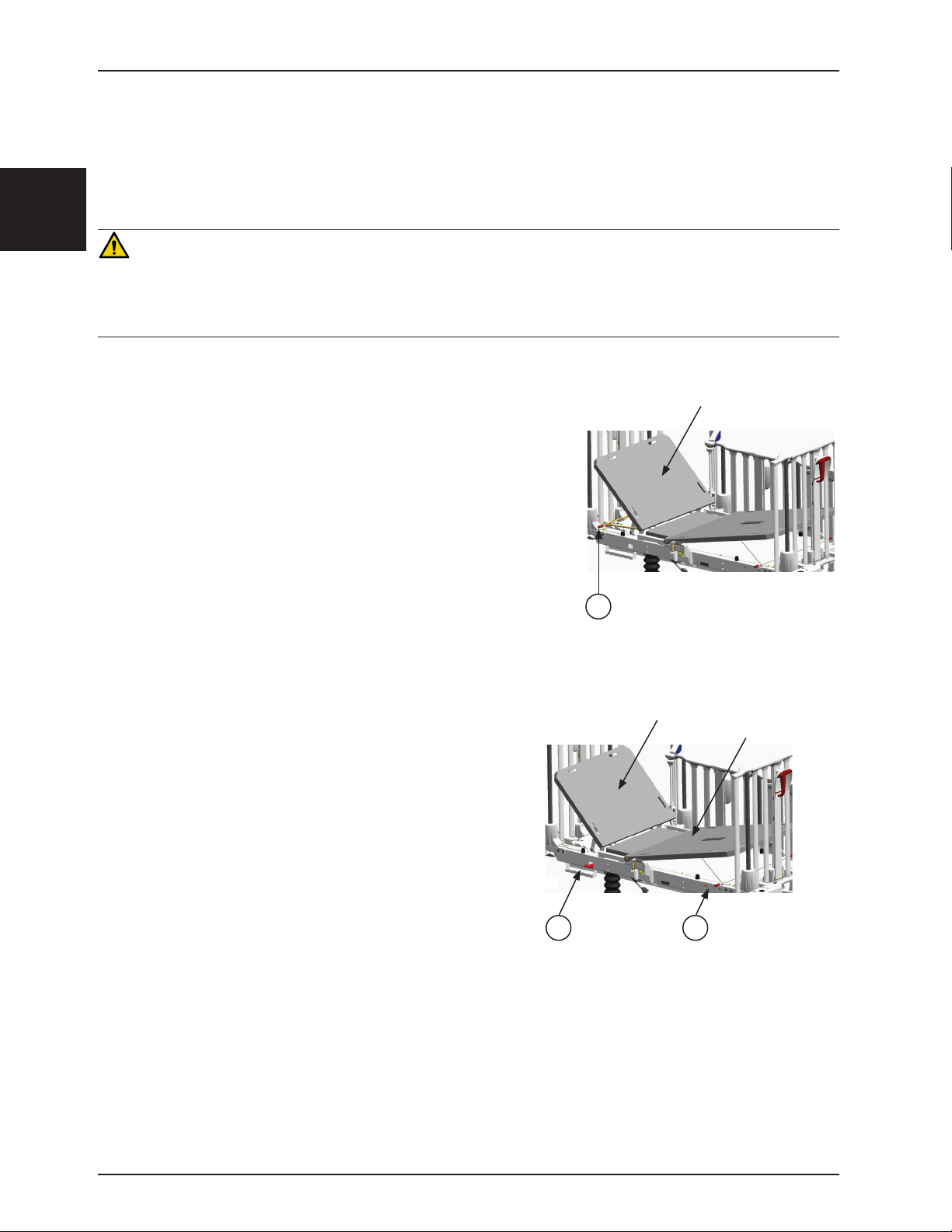
Français
Fonctionnement
POSITIONNER LES SECTIONS DE TÊTE ET DE PIED
REMARQUE
Deux sections de tête sont offertes : à commande manuelle et assistée par pneumatique. La section de pied est du
type manuel.
AVERTISSEMENT
• Afin d’éviter toute blessure au patient, assurez-vous que le patient repose en toute sécurité dans le sommier avant de manipuler
la section de tête ou de pied ou d’abaisser un côté de sûreté.
• Afin d’éviter toute blessure lorsque la section de tête manuelle ou la section de pied du sommier est élevée ou abaissée,
assurez-vous que le support est bien engagé dans les arrêts de support avant de relâcher la section de tête ou de pied.
POSITIONNER LA SECTION DE TÊTE MANUELLE
• Pour monter la section de tête, soulevez-la manuellement. À mesure que
la section de tête sera soulevée, le support (A) suivra et s’engagera dans
les arrêts de l’une des trois positions angulaires possibles : 25°, 40° et 55°
(voir la Figure 4).
• Pour modifier la position angulaire de la section de tête, soulevez-la
légèrement d’une main et de l’autre, soulevez le support par sa
poignée gauche ou droite (A) afin de le dégager des arrêts. Placez
le support à la position désirée. Pour abaisser complètement la
section de tête, maintenez la poignée tout en baissant la section de
tête jusqu’en bas, puis relâchez le support (voir la Figure 4).
Section de tête
POSITIONNER LA SECTION DE TÊTE ASSISTÉE PAR PNEUMATIQUE
• Pour monter la section de tête, soulevez le levier d’activation gauche
ou droit (B) tout en exerçant momentanément une légère
poussée sous le coin supérieur gauche ou droit de la section
de tête pour amorcer sa montée assistée (voir la Figure 5).
Relâchez le levier d’activation lorsque la position désirée est
obtenue.
• Pour baisser la section de tête, exercez une poussée vers
le bas au sommet de la section de tête tout en soulevant
le levier d’activation gauche ou droit (B) (voir la Figure 5).
Relâchez le levier d’activation lorsque la position désirée est
obtenue.
POSITIONNER LA SECTION DE PIED
• Pour monter la section de pied, soulevez-la manuellement. À
mesure que la section de pied sera soulevée, le support suivra et
s’engagera dans les arrêts de l’une des deux positions angulaires
possibles : 6° et 12° (voir la Figure 5).
• Pour baisser la section de pied à la position suivante ou pour
la baisser complètement, soulevez-la d’une main et soulevez
de l’autre main l’une des poignées du support (C) pour le
dégager des arrêts (voir la Figure 5). Baissez la section
de pied et relâchez le support pour qu’il s’engage dans
les arrêts de la nouvelle position ou maintenez le support
soulevé pour baisser complètement la section de pied.
Figure 5 - Positionnement de la section
Figure 4 - Positionner la section
A
de tête
Section de tête
Section de pied
B
C
de tête et de la section de pied assisté
par pneumatique
Retour à la table des matières
2-16 1900-009-001 REV B w ww.stryker.com
Page 64

Fonctionnement
FONCTIONNEMENT DES CÔTÉS DE SÛRETÉ
AVERTISSEMENT
• Afin d’éviter toute blessure au patient, assurez-vous que les membres du patient ne sont pas à proximité des parties mobiles
d’un côté de sûreté qui doit être relevé ou abaissé. Assurez-vous que le côté de sûreté est bien verrouillé après l’avoir manipulé.
• Les côtés de sûreté doivent toujours être maintenus en position haute, et le sommier en position basse, sauf lorsque le patient
est soigné. Ne laissez jamais un patient sans surveillance lorsque les côtés de sûreté sont abaissés.
• Afin d’éviter les chutes et les blessures, assurez-vous que les côtés de sûreté et les portes d’accès sont bien verrouillés après
les avoir manipulés ou avant de laisser un patient sans surveillance.
REMARQUE
Afin de vous assurer que le côté est bien verrouillé à la position voulue,
vérifiez que les indicateurs fléchés (B) sont bien alignés.
• Pour relever un côté de sûreté latéraux et d’extrémité, saisissez
la traverse supérieure ou la poignée (A) et soulevez le côté à
la hauteur désirée. Nul besoin de tourner la poignée. Le côté se
verrouillera à l’une des trois positions possibles : 23 cm, 36 cm et
66 cm. Un « clic » se fera entendre chaque fois qu’une position de
verrouillage sera atteinte (voir la Figure 6).
• Pour abaisser un côté de sûreté latéraux et d’extrémité, saisissez
la poignée (A). Pressez la gâchette, tournez la poignée vers la
gauche ou la droite et abaissez le côté à la hauteur désirée.
Ramenez la poignée en position verticale pour verrouiller le côté à
la position désirée (voir la Figure 6).
A
Français
REMARQUE
• Pour des raisons de sécurité, les côtés de sûreté latéraux et
d’extrémité s’arrêtent automatiquement à la position 23 cm, même
si la poignée est maintenue tournée pendant la descente.
• Certaines civières peuvent ne pas être munies de cet arrêt
automatique double à la position 23 cm.
FONCTIONNEMENT DES PORTES D’ACCÈS (EN OPTION)
AVERTISSEMENT
Afin d’éviter les chutes et les blessures, assurez-vous que
les deux indicateurs d’ouverture/fermeture (situés sur les
boutons de déverrouillage) de la porte d’accès sont tous
deux de couleur verte lorsque la porte est fermée et
verrouillée.
• Pour ouvrir une porte d’accès, pressez les deux
boutons de déverrouillage (A) situés sur la barre de
pivotement de chaque porte d’accès et ouvrez la porte
d’accès. Les indicateurs d’ouverture/fermeture (B)
seront de couleur jaune (voir la Figure 7).
• Pour fermer une porte d’accès, ramenez-la en
position fermée, et elle se verrouillera d’elle-même.
Les indicateurs d’ouverture/fermeture (B) seront
de couleur verte. Si l’un d’eux demeure jaune, cela
signifie que la porte n’est pas complètement fermée;
rouvrez et refermez la porte (voir la Figure 7).
B
B
Figure 6 - Côtés de sûreté latéraux et
d’extrémité
A
Figure 7 - Porte d’accès
Retour à la table des matières
www.stryker.com 1900-009-001 REV B 2 -17
Page 65

Français
D
C
E
A
B
F
Fonctionnement
FONCTIONNEMENT DE LA BALANCE (EN OPTION)
La balance permet d’obtenir une lecture du poids du patient en livres (lb) ou en kilogrammes (kg) avec une précision
de ± 0,5 lb (0,2 kg) à 50 lbs (22 kg) ou moins et ± 1,0 lbs (0,4 kg) à ≥ 50 lbs (22 kg) quand plat. Cette lecture peut
être conservée en mémoire. Le système permet aussi d’ajouter ou d’enlever un appareil ou un accessoire de la civière
sans en retirer le patient.
MODULE DE COMMANDE DE LA BALANCE
MISE EN GARDE
• Afin d’éviter d’endommager les composants électroniques de la balance, ne vous appuyez pas sur le support d’accessoires
abritant le module de commande de la balance.
• N’utilisez pas de tige à soluté fixe à deux ou trois étages au pied d’une civière munie de la balance.
QDF19-0867
Figure 8 - Module de commande de la balance
Ce tableau renvoie à la Figure 8 ci-dessus.
Active la balance. Une pesée s’effectue dès que cette touche est pressée et relâchée. Un
poids s’affiche à l’écran quatre à dix secondes plus tard. Aucun poids n’est cependant affiché
si l’icône « Error - Ex.x » ou l’icône de mouvement
Weigh/On
A
(Peser/Marche)
Memory (Mémoire) Mise en mémoire du résultat de la pesée ou rappel à l’écran du poids enregistré en mémoire.
B
Zero (Remise à zéro) Mise à zéro du poids affiché à l’écran et du poids enregistré en mémoire.
C
lb / kg Changer d’unité de mesure (lb ou kg).
D
Change Equipment
E
(Modifier le matériel)
Écran de la balance
F
l’erreur ou stabiliser la civière avant d’utiliser la balance à nouveau (voir la Liste des codes
d’erreur du Manuel d’entretien).
REMARQUE
La balance ne fonctionne pas en mode continu. Celle-ci doit être activée en pressant la touche
Weigh/On (Peser/Marche) chaque fois qu’une lecture du poids du patient est requise.
Retirer ou ajouter de l’équipement à la civière sans en retirer le patient.
La balance se mettra hors fonction après 30 secondes d’inactivité, sauf pendant l’opération
d’ajout/retrait d’équipement, où le délai est de trois minutes. Elle peut être réactivée simplement
en pressant la touche Weigh/On (Peser/Marche).
Si le patient pèse plus de 54 kg, le message « Error - E05 » apparaîtra à l’écran pour indiquer
que la balance ne doit pas être utilisée dans ces conditions, car sa capacité maximale de
pesée est dépassée.
D’autres messages d’erreur sont susceptibles d’apparaître à l’écran lors de l’utilisation de la
balance. Référez-vous à la Liste des codes d’erreur du Manuel d’entretien afin de comprendre
leur signification et les mesures à prendre lorsqu’ils apparaissent.
lb / kg
Modifier
le matériel
Remise
à zéro
Mémoire
Peser
Marche
apparaît à l’écran. Il faudra corriger
Retour à la table des matières
2-18 1900-009-001 REV B w ww.stryker.com
Page 66

Fonctionnement
UTILISATION DE LA BALANCE
MISE EN GARDE
La zone de pesée de la balance comprend toute la partie supérieure de la civière, incluant les côtés de sûreté, les supports
d’accessoires, les crochets pour sac de drainage, les supports à dossier (en option) et porte-moniteur (en option) situés sous le
sommier. Lors d’une pesée ou d’une mise à zéro, assurez-vous qu’aucun objet extérieur n’est en contact avec la civière.
REMARQUE
Français
L’icône
incapable d’effectuer une lecture du poids du patient parce que la civière est instable. Stabilisez la civière puis répétez
l’opération en cours.
Les touches Memory (Mémoire), Change Equipment (Modifier le matériel) et Zero (Remise à zéro) peuvent être
utilisées pour interrompre le processus de lecture du poids lorsque l’opération désirée ne nécessite pas l’affichage
d’un poids.
peut apparaître à n’importe quel moment de l’utilisation de la balance. Il indique que la balance est
A. PRÉPARATION (MISE À ZÉRO) DE LA BALANCE POUR UN NOUVEAU PATIENT
• Préparez la civière pour le nouveau patient (draps, oreillers, équipement, etc.).
• Pressez/relâchez la touche Weigh/On (Peser/Marche) pour activer la balance. Une lecture de poids
apparaîtra à l’écran après 4 à 10 secondes d’attente durant lesquelles une ligne de trois traits d’union
clignotera.
•
Pressez et maintenez enfoncée la touche Zero (Remise à zéro) pendant au moins deux secondes. Relâchez
la touche de 4 à 10 secondes plus tard, le poids affiché et celui mis en mémoire seront ramenés à zéro.
•
Installez le patient dans la civière et pressez/relâchez la touche Weigh/On (Peser/Marche). Le poids du
patient s’affichera 4 à 10 secondes plus tard.
MISE EN GARDE
Afin de maintenir la précision de la balance, il est recommandé de la remettre à zéro au moins une fois par semaine. Notez que le
patient devra être retiré de la civière avant de mettre la balance à zéro.
B. ENREGISTREMENT EN MÉMOIRE D’UNE LECTURE DE POIDS
• Pressez/relâchez la touche Weigh/On (Peser/Marche) pour activer la balance. Attendez l’affichage du
poids à l’écran.
• Pressez et maintenez enfoncée pendant deux secondes la touche Memory (Mémoire). Dès que le
message « Memory » apparaît à l’écran, relâchez la touche. Le poids lu précédemment est maintenant
mis en mémoire.
C. RAPPEL À L’ÉCRAN DU POIDS ENREGISTRÉ EN MÉMOIRE
• Pressez/relâchez la touche Weigh/On (Peser/Marche) pour activer la balance. Passez directement à
l’étape suivante sans attendre l’affichage du poids.
• Pressez la touche Memory (Mémoire). « Memory » apparaîtra à l’écran, tout comme la valeur enregistrée
en mémoire. Pour sortir du mode Memory (Mémoire), pressez/relâchez de nouveau la touche Weigh/On
(Peser/Marche).
D. MISE À ZÉRO DU POIDS AFFICHÉ À L’ÉCRAN ET DU POIDS ENREGISTRÉ EN MÉMOIRE
• Pressez la touche Weigh/On (Peser/Marche) pour activer la balance. Passez directement à l’étape
suivante sans attendre l’affichage du poids.
• Pressez et maintenez enfoncée la touche Zero (Remise à zéro) pendant au moins deux secondes.
Relâchez la touche de 4 à 10 secondes plus tard, le poids affiché et celui mis en mémoire seront ramenés
à zéro.
Retour à la table des matières
www.stryker.com 1900-009-001 REV B 2 -19
Page 67

Français
Fonctionnement
E. MISE À ZÉRO DE LA MÉMOIRE SEULEMENT
• Pressez la touche Weigh/On (Peser/Marche) pour activer la balance. Passez directement à l’étape
suivante sans attendre l’affichage du poids.
• Pressez simultanément et maintenez enfoncées pendant au moins deux secondes les touches Memory
(Mémoire) et Zero (Remise à zéro). Relâchez les touches. L’écran affichera 0.0 lb/kg.
F. AJOUT OU RETRAIT D’ÉQUIPEMENT AVEC UN PATIENT DANS LA CIVIÈRE
• Pressez la touche Weigh/On (Peser/Marche) pour activer la balance. Vous pouvez passer immédiatement
à la prochaine étape, mais si vous désirez comparer le poids résultant de la procédure d’ajout/retrait
d’équipement avec le poids du patient avant la procédure, laissez le processus suivre son cours jusqu’à
l’affichage du poids et notez ce poids.
• Pressez la touche Change Equipment (Modifier le matériel). Quatre à dix secondes plus tard, le message
« Change Equipment » apparaîtra à l’écran. REMARQUE : La balance s’éteindra automatiquement si cette
étape prend plus de trois minutes à s’accomplir; il faudra alors reprendre l’opération depuis le début.
•
Ajoutez ou retirez l’équipement de la civière. Puis, pressez de nouveau la touche Change Equipment
le matériel).
Quatre à dix secondes plus tard, le poids du patient inchangé réapparaîtra à l’écran.
REMARQUE
Afin d’éviter de fausser la lecture du poids d’un patient, le mode Change Equipment (Modifier le matériel) doit être
utilisé chaque fois qu’un objet, quel qu’il soit, est ajouté à la zone de pesée de la balance ou retiré de celle-ci.
Advenant le cas où un objet aurait été prématurément (sans la procédure d’ajout/retrait d’équipement) ajouté à une
civière occupée par un patient ou retiré de celle-ci, il faudra impérativement mettre la balance à zéro (voir la procédure
A à la page 19) après avoir retiré le patient de la civière.
(Modifier
G. CHANGEMENT D’UNITÉ DE MESURE DU POIDS
• Pressez la touche Weigh/On (Peser/Marche) pour activer la balance. Une lecture de poids apparaîtra à
l’écran après 4 à 10 secondes d’attente.
• Pressez la touche lb / kg pour passer de livres (lb) à kilogrammes (kg), ou l’inverse.
• La touche lb / kg peut être rendue inopérante afin de prévenir son activation par inadvertance. Pour ce
faire, pressez et maintenez enfoncées pendant au moins deux secondes les touches lb / kg et Memory
(Mémoire). Faites de même pour rendre de nouveau accessible la touche lb / kg.
REMPLACEMENT DES BATTERIES
Le système électronique de la balance est alimenté par quatre batteries alcalines
de type C (1,5 V). Pour les remplacer, référez-vous à la Figure 9 et suivez les
étapes 1 à 4 ci-dessous.
REMARQUE
L’icône apparaîtra à l’écran pour signaler que les batteries doivent être
remplacées.
1. À l’aide d’un tournevis Phillips, retirez les deux vis (A) fixant le couvercle (B)
du boîtier des batteries.
2. Retirez les quatre batteries et remplacez-les par quatre nouvelles batteries
alcalines de type C (1,5 V). Assurez-vous de respecter la polarité des
batteries en les installant dans le boîtier.
3. Replacez le couvercle.
4. Mettez la balance à zéro (voir la procédure A à la page précédente) sans
patient dans la civière avant de la remettre en service.
B
A
Figure 9 - Remplacement des
batteries
MISE EN GARDE
• N’utilisez que des batteries alcalines 1,5 V. L’utilisation de batteries autres que celles spécifiées risque d’endommager les
composants électroniques de la balance.
• Retirez les batteries de leur emplacement lorsque la balance ou la civière ne sont pas utilisés pendant de longues périodes.
Retour à la table des matières
2-20 1900-009-001 REV B ww w.stryker.com
Page 68

Accessoires
BRACKET
UTILISATION DU SUPPORT D’ACCESSOIRES RÉGULIER
Des supports d’accessoires réguliers sont installés aux quatre coins de la civière. Ces supports sont conçus pour
supporter un support vertical de bouteille à oxygène (en option), des tiges à soluté amovibles (en option) et/ou le toit
de protection rétractable (en option). Un pare-chocs en caoutchouc pratique complète le support d’accessoires (voir
la Figure 10).
Français
PROTECTIVE TOP MOUNTING
DOUILLE DE MONTAGE DU
TOIT DE PROTECTION
SOCKET
RUBBER BUMPER
PARE-CHOCS EN
CAOUTCHOUC
REMOVABLE IV POLE INSTALLED
TIGE À SOLUTÉ AMOVIBLE
(
NOT INCLUDED
INSTALLÉE (NON COMPRISE)
SUPPORT D’ACCESSOIRES
STANDARD ACCESSORY
RÉGULIER
)
Figure 10 - Support d’accessoires régulier
UTILISATION DU SUPPORT D’ACCESSOIRES DE LUXE (EN OPTION)
La civière pédiatrique peut être munie de supports d’accessoires de luxe (en option) destinés à l’installation d’équipements
nécessaires aux soins des patients. Conçus pour s’installer à une ou aux deux extrémités de la civière, ils sont fournis
en ensemble de deux ou de quatre supports. Référez-vous à la Figure 11 pour les fonctions des douilles de support.
MISE EN GARDE
La zone de pesée de la balance comprend toute la partie supérieure de la civière, incluant les côtés de sûreté, les supports
d’accessoires, les crochets pour sac de drainage, les supports à dossier (en option) et porte-moniteur (en option) situés sous le
sommier. Lors d’une pesée ou d’une mise à zéro, assurez-vous qu’aucun objet extérieur n’est en contact avec la civière.
DOUILLE POUR SUPPORT
UPRIGHT O
DE BOUTEILLE D’OXYGÈNE
HOLDER SOCKET
DOUILLE DE RANGEMENT
PERMANENT IV POLE HANGER
DES CROCHETS DE LA TIGE À
DOUILLE POUR TIGE À
SOLUTÉ PERMANENTE
STORAGE SOCKET
SOLUTÉ PERMANENTE
PERMANENT IV POLE
SOCKET
DOUILLE POUR TIGE
STRYKER
À SOLUTÉ 1,3 CM DE
1/2
SOCKET
STRYKER
IV POLE
"
2
VERTICAL
(NECESSITE QUATRE SUPPORTS D’ACCESSOIRES)
BOTTLE
PROTECTIVE TOP MOUNTING SOCKETS
DOUILLES DE MONTAGE DU TOIT DE PROTECTION
REQUIRES SET OF FOUR ACCESSORY BRACKETS
(
OR
OU
STRYKER ACCESSORY SOCKETS
DOUILLES POUR ACCESSOIRES STRYKER
Figure 11 - Support d’accessoires de luxe
www.stryker.com 1900-009-001 REV B 2-21
)
DOUILLE POUR SUPPORT DE
UPRIGHT O
BOTTLE
BOUTEILLE D’OXYGÈNE VERTICAL
2
HOLDER SOCKET
DOUILLE DE RANGEMENT DES CROCHETS
PERMANENT IV POLE HANGER
DE LA TIGE À SOLUTÉ PERMANENTE
STORAGE SOCKET
PERMANENT IV POLE
DOUILLE POUR TIGE À
SOCKET
SOLUTÉ PERMANENTE
STRYKER
1/2
DOUILLE POUR TIGE À
SOLUTÉ 1,3 CM DE STRYKER
SOCKET
"
IV POLE
Retour à la table des matières
Page 69

Accessoires
A
Français
UTILISATION DU COLLET POUR BOUTEILLE D’OXYGÈNE (EN OPTION)
Un collet pour bouteille d’oxygène (A) peut être
installé sur le capot de la base afin de tenir en place
une bouteille d’oxygène installée dans la cavité
prévue à cette fin sur le capot (voir la Figure 12).
Glissez le bout de la bouteille dans la cavité jusqu’à
insertion complète.
FONCTIONNEMENT DU BRAS D’ATTACHE (EN OPTION)
Le bras d’attache permet à une tige à soluté sur roulettes de suivre la civière en déplacement. Assurez-vous toujours
que la tige à soluté est bien fixée au bras d’attache avant le transport afin d’éviter d’endommager la tige à soluté ou
de causer des blessures au patient ou à l’utilisateur (voir la Figure 13).
1. Soulevez le bras d’attache de sa position de rangement.
2. Pivotez le bras vers l’endroit désiré.
3. Tournez le bouton (A) dans le sens antihoraire pour desserrer le collier de serrage (C).
4. Pivotez le bouton (A) hors du collier de serrage (B). Ouvrez le collier (C).
5. Placez la tige à soluté à l’intérieur du collier de serrage (B). Fermez le collier (C) autour de la tige à soluté et
ramenez le bouton (A) à sa position d’origine.
6. Tournez le bouton dans le sens horaire pour le serrer. La tige à soluté est maintenant prête à suivre la civière en
déplacement.
7. Pour retirer la tige à soluté du bras d’attache, tournez le bouton (A) dans le sens antihoraire pour desserrer le
collier de serrage.
8. Pivotez le bouton hors du collier de serrage (B), ouvrez le collier et retirez la tige à soluté du bras d’attache.
9. Rangez le bras d’attache.
Figure 12 - Collet pour bouteille d’oxygène
MISE EN GARDE
Rangez toujours un bras d’attache non utilisé afin d’éviter de l’endommager lorsque la civière est déplacée.
Figure 13 - Bras d’attache
Retour à la table des matières
2-22 1900-009-001 REV B ww w.stryker.com
Page 70

Accessoires
FONCTIONNEMENT DE LA TIGE À SOLUTÉ FIXE À DEUX ÉTAGES (EN OPTION)
AVERTISSEMENT
Assurez-vous que des politiques appropriées sont mises en place pour assurer la sécurité du patient lorsqu’une tige à soluté ou une
bouteille d’oxygène est utilisée. Le patient ne doit pas y avoir accès ni les manipuler.
Pour utiliser la tige à soluté fixe à deux étages, référez-vous à la Figure 14 et aux étapes 1 à 4 ci-dessous :
1. Soulevez la tige de sa position de rangement, redressez-la puis enfoncez-la dans son socle de fixation pour la
bloquer.
2. Pour augmenter la hauteur de la tige, tirez sur la section télescopique (A) jusqu’à ce qu’elle se verrouille
automatiquement à son extension maximale. Il n’y a pas de position intermédiaire pour cette section.
3. Tournez les crochets (B) de la tige vers la position désirée et accrochez-y le sac de soluté.
4. Pour ranger la tige à soluté, tournez le verrou (C) dans le sens horaire jusqu’à ce que la section (A) descende.
Sortez la tige de son réceptacle, pliez-la et rangez les crochets de la tige dans l’espace prévu à cette fin sur le
support d’accessoires adjacent.
Français
Figure 14 - Tige à soluté à deux étages
DÉTAIL DU VERROU DE LA TIGE À SOLUTÉ
MISE EN GARDE
• Le poids des sacs de soluté ne doit pas dépasser 18 kg.
• N’utilisez pas de tige à soluté fixe à deux ou trois étages au pied d’une civière munie de la balance.
Retour à la table des matières
www.stryker.com 1900-009-001 REV B 2-23
Page 71

Accessoires
FONCTIONNEMENT DE LA TIGE À SOLUTÉ À TROIS ÉTAGES (EN OPTION)
Français
AVERTISSEMENT
Assurez-vous que des politiques appropriées sont mises en place pour assurer la sécurité du patient lorsqu’une tige à soluté ou une
bouteille d’oxygène est utilisée. Le patient ne doit pas y avoir accès ni les manipuler.
Pour utiliser la tige à soluté à trois étages, référez-vous à la Figure 15 et suivez les étapes 1 à 5 ci-dessous :
1. Soulevez la tige de sa position de rangement, redressez-la puis enfoncez-la dans son socle de fixation pour la
bloquer.
2. Pour augmenter la hauteur de la tige, tirez sur la première section télescopique (A) jusqu’à ce qu’elle se verrouille
automatiquement à son extension maximale. Il n’y a pas de position intermédiaire pour cette section.
3. Pour élever davantage la tige, tirez sur la deuxième section télescopique (B). Il suffit de relâcher la section (B) à
n’importe quelle hauteur pour qu’elle se verrouille automatiquement en place. Pour abaisser la section, poussez
vers le haut la partie rouge de la poignée tout en tenant la section et descendez-la à la hauteur désirée. Relâchez
la partie rouge de la poignée pour fixer la section en place.
4. Tournez les crochets de la tige (C) à la position voulue et suspendez-y les sacs de soluté.
5. Pour ranger la tige, poussez vers le haut la partie rouge de la poignée (D) tout en tenant la section (B) et
descendez-la complètement. Tournez le verrou (E) dans le sens horaire pour abaisser la section (A). Sortez la
tige de son socle, pliez-la et rangez les crochets dans l’espace prévu à cette fin sur le support d’accessoires
adjacent.
DÉTAIL DU VERROU
DE LA TIGE À SOLUTÉ
DÉTAIL DE LA POIGNÉE DE LA TIGE À SOLUTÉ
Figure 15 - Tige à soluté à trois étages
MISE EN GARDE
• Le poids des sacs à soluté ne doit pas dépasser 18 kg.
• N’utilisez pas de tige à soluté fixe à deux ou trois étages au pied d’une civière munie de la balance.
Retour à la table des matières
2-24 1900-009-001 REV B www.stryker.com
Page 72

Accessoires
UTILISATION DU SUPPORT À DOSSIER / PORTE-MONITEUR (EN OPTION)
Le support à dossier (6,4 cm de hauteur) et le porte-moniteur (11,4 cm de hauteur), situés sous le sommier, à gauche
ou à droite ou des deux côtés de la civière, permettent de faire suivre le dossier du patient lorsqu’il est transféré d’unité
de soins ou d’installer un moniteur sur la civière.
Français
Figure 16 - Support à dossier / porte-moniteur
Retour à la table des matières
www.stryker.com 1900-009-001 REV B 2-25
Page 73
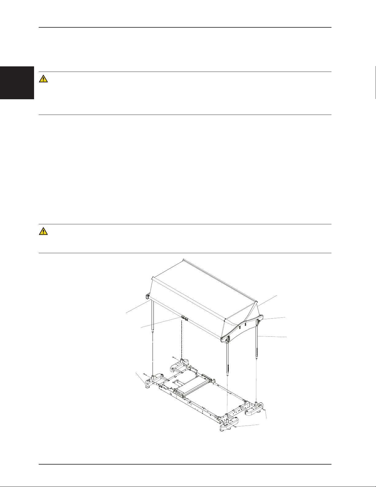
Français
Accessoires
TOIT DE PROTECTION D’INSTALLATION (FA64074-BIL)
Toit conçu pour fermer toutes ouvertures possibles au dessus des côtés de sûreté.
AVERTISSEMENT
• Retirez le patient du lit avant d’entreprendre l’installation de l’accessoire.
• Si la civière qui recevra le toit de protection est équipée du dispositif de pesée (en option), assurez-vous de le fermer avant
d’entreprendre l’installation du toit. Une fois l’installation terminée, référez-vous au Guide de l’utilisateur de la civière pour mettre
la balance à zéro.
Necessary Tools:
• Clé 9/16”
Procédure : (voir le schéma 17)
Remarque: Deux personnes sont nécessaires pour installer le toit de protection.
1. Installez les 4 poteaux dans les deux structures de plastique du toit de la façon suivante :
2. Pressez la goupille d’ancrage, située dans la partie supérieure du poteau et insérez le poteau dans un des quatre
orifices prévus à cette fin sur les structures de plastique.
3. Tourner le poteau jusqu’à ce que la goupille s’insère dans l’orifice qui lui est destiné sur la face externe de la
structure de plastique.
4. Installez les quatre poteaux du toit dans les douilles des supports d’accessoires et verrouillez les poteaux en place
à l’aide des goupilles d’attelage.
MISE EN GARDE
Avant d’utiliser le toit de protection, il est très important pour la sécurité du patient de s’assurer, par un examen minutieux, que le toit
a été correctement installé sur la civière.
Toit de protection
Traverse inférieure
Boutons de déverrouillage
Support d'accessoires
Structure de plastique
Poteau
Goupille
Figure 17
Retour à la table des matières
2-26 1900-009-001 REV B ww w.stryker.com
Page 74

Accessoires
TOIT DE PROTECTION D’INSTALLATION (FA64074-BIL)
1. Pour ouvrir le toit de protection du côté droit ou gauche de la civière, rapprochez les deux boutons de déverrouillage de la traverse inférieure (voir la figure 2), soulevez la traverse et rabattez le toit vers le côté opposé jusqu’à
ce que l’ouverture désirée soit atteinte.
2. Pour refermer le toit, saisissez la traverse inférieure du toit et ramenez-la vers vous jusqu’à ce qu’elle se verrouille
en place. Assurez-vous que le verrou à ressort de chaque extrémité de la traverse inférieure est bien engagée
dans l’orifice.
Français
Figure 18
AVERTISSEMENT
• Assurez-vous, pour la sécurité du patient, que les extrémités des deux traverses inférieures sont correctement
verrouillées avant de laisser le patient sans surveillance.
• Afin d’éviter des blessures aux mains et /ou aux doigts, n’utilisez jamais les bras latéraux articulés du toit pour le refermer.
Manipuler toujours le toit par le centre de la traverse inférieure.
MISE EN GARDE
N’utilisez pas le toit de protection pour déplacer la civière.
TOIT DE PROTECTION NETTOYAGE
La membrane de plastique du toit de protection peut être nettoyée quotidiennement à l’aide de savons doux ou de
nettoyants à base d’ammoniaque en faible concentration tels les nettoyants à vitre.
Retour à la table des matières
www.stryker.com 1900-009-001 REV B 2-27
Page 75
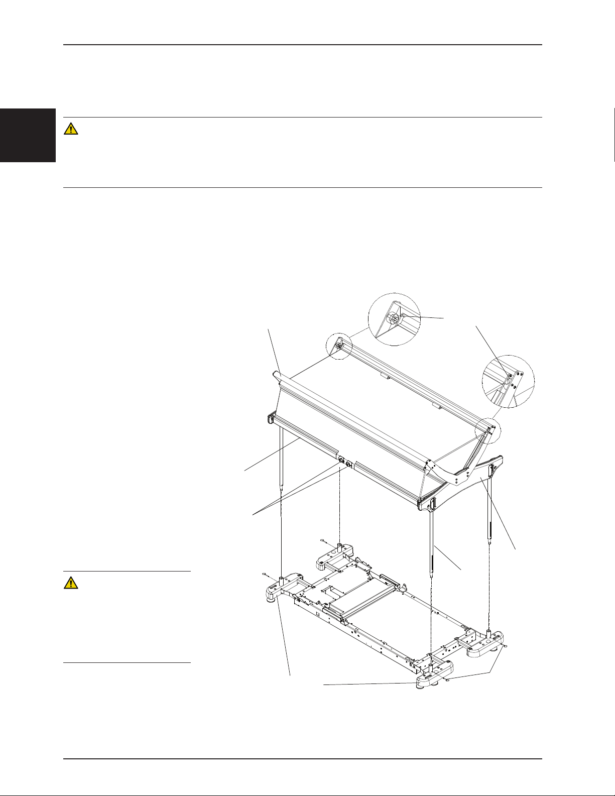
Français
QUE
Accessoires
TOIT DE PROTECTION AVEC SUPPORTS D’INSTALLATION (FA64183-BIL)
Toit conçu pour fermer toutes ouvertures possibles au dessus des côtés de sûreté.
AVERTISSEMENT
• Retirez le patient du lit avant d’entreprendre l’installation de l’accessoire.
• Si la civière qui recevra le toit de protection est équipée du dispositif de pesée (en option), assurez-vous de le fermer avant
d’entreprendre l’installation du toit. Une fois l’installation terminée, référez-vous au Guide de l’utilisateur de la civière pour mettre
la balance à zéro.
Necessary Tools:
• Clé 9/16’’
Procédure: (voir le schéma 19)
Remarque: Deux personnes sont nécessaires pour installer le toit de protection.
1. Installez les 4 poteaux
dans les deux structures
de plastique du toit de la
façon suivante : Pressez la
goupille d’ancrage, située
dans la partie supérieure
du poteau et insérez le
poteau dans un des quatre
orifices prévus à cette
fin sur les structures de
plastique.
2. 2. Tourner le poteau
jusqu’à ce que la goupille
s’insère dans l’orifice qui
lui est destiné sur la face
externe de la structure de
plastique.
3. Installez les quatre poteaux
du toit dans les douilles des
supports d’accessoires et
verrouillez les poteaux en
place à l’aide des goupilles
d’attelage.
SUPPORT DE POSITIONNEMENT
TRAVERSE INFÉRIEURE
BOUTONS DE DÉVERROUILLAGE
POINTS D'ANCRAGE
STRUCTURE DE PLASTI
POTEAU
AVERTISSEMENT
Il est très important pour la sécurité
du patient que l’ensemble est
soigneusement inspecté avant son
utilisation afin de s’assurer qu’elle
est correctement et solidement
fixés.
SUPPORTS D'ACCESSOIRES
Retour à la table des matières
2-28 1900-009-001 REV B www.stryker.com
GOUPILLES
Figure 19
Page 76
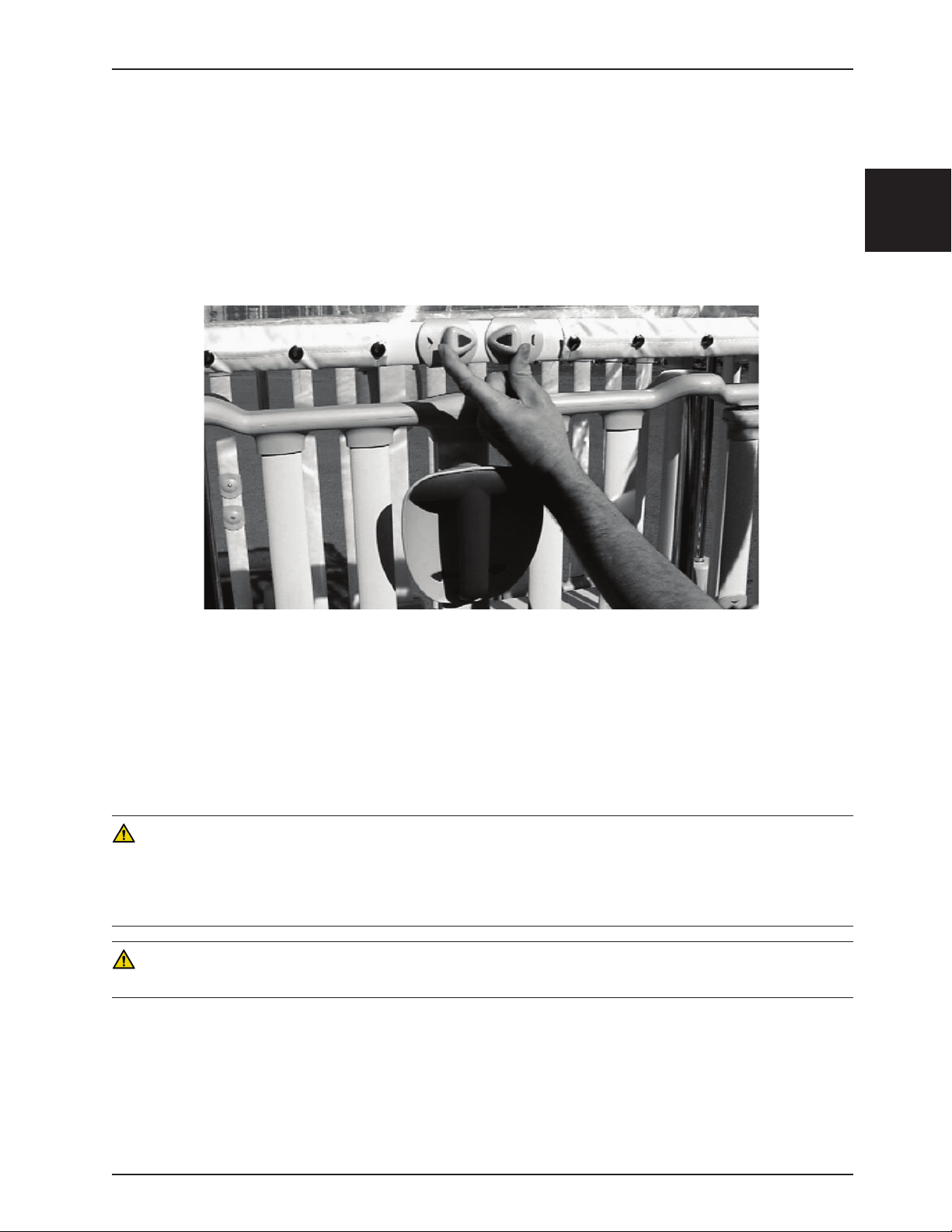
Accessoires
TOIT DE PROTECTION AVEC SUPPORTS D’INSTALLATION (FA64183-BIL)
Remarque: À moins d’indication contraire, les éléments mentionnés et soulignés de cette procédure d’utilisation
réfèrent à la figure 19.
1. Pour ouvrir partiellement le toit de protection, rapprochez les deux boutons de déverrouillage figure 2), soulevez la
traverse inférieure jusqu’à ce qu’elle ait légèrement dépassé les points d’ancrage, relâchez les boutons de déverrouillage et ramener la traverse vers soi afin que ses extrémités reposent dans les points d’ancrage
Remarque: Assurez-vous que les extrémités de la traverse sont bien positionnées dans les points d’ancrage en
tentant de déplacer la traverse vers le bas sans activer les boutons de déverrouillage.
Français
Figure 20
2. Pour ouvrir complètement le toit, déverrouillez la traverse inférieure en rapprochant les boutons de déverrouillage
et, tout en les maintenant rapprochés, soulevez la traverse jusqu’à ce que l’ouverture maximale du toit soit atteinte.
Relâchez les boutons lorsque la traverse aura dépassé les points d’ancrage.
3. Pour refermer un toit partiellement ouvert, soulevez la traverse inférieure pour dégager ses extrémités des points
d’ancrage, rapprochez ensuite les boutons de déverrouillage et ramenez la traverse à sa position d’origine.
Relâchez les boutons de déverrouillage.
4. Pour refermer un toit complètement ouvert, saisissez la traverse inférieure, rapprochez les boutons de déverrouillage et ramenez la traverse à sa position d’origine. Relâchez les boutons de déverrouillage.
AVERTISSEMENT
• Avant de laisser le patient sans surveillance après avoir fermé le toit de protection, assurez-vous que les extrémités
des deux traverses inférieures sont correctement verrouillées.
• Afin d’éviter des blessures aux mains et /ou aux doigts, n’utilisez jamais les bras latéraux articulés du toit pour le refermer.
Manipuler toujours le toit par le centre de la traverse inférieure.
MISE EN GARDE
N’utilisez pas le toit de protection pour déplacer la civière.
TOIT DE PROTECTION AVEC SUPPORTS NETTOYAGE
La membrane de plastique du toit de protection peut être nettoyée quotidiennement à l’aide de savon doux ou de nettoyants à base d’ammoniaque en faible concentration tels les nettoyants à vitre.
Retour à la table des matières
www.stryker.com 1900-009-001 REV B 2-29
Page 77

Français
Nettoyage
Ces directives expliquent les méthodes de nettoyage recommandées pour les matelas de civière. Elles décrivent
l’entretien requis pour nettoyer et désinfecter adéquatement les matelas entre les séjours de patients et pour prolonger
la durée de vie des matelas.
MÉTHODE DE NETTOYAGE RECOMMANDÉE
• Lavez toutes les surfaces du matelas à la main, avec de l’eau tiède et un détergent doux.
• Séchez soigneusement.
• Appliquez une solution désinfectante en aérosol, liquide ou sous forme de lingettes pré-humectées (ne trempez pas le matelas).
• Nettoyez selon le protocole de l’hôpital applicable aux matelas de lits.
• Essuyez l’excès de désinfectant.
• Rincez à l’eau claire.
• Laissez sécher la surface.
DÉSINFECTANTS RECOMMANDÉS
IMPORTANT : DILUEZ TOUS LES DÉSINFECTANTS SELON LES DIRECTIVES DU FABRICANT
De l’eau de Javel diluée ou des désinfectants germicides phénoliques ou quaternaires dilués sont recommandés s’ils
sont utilisés dans les concentrations recommandées par le fabricant.
L’eau de Javel, généralement 5,25 % d’hypochlorure de sodium, doit être diluée au 1/10 dans de l’eau.
NETTOYANTS CORROSIFS À RINCER
Ces produits NE sont PAS considérés comme des détergents doux. Ils sont corrosifs et risquent d’endommager le
matelas de la civière s’ils ne sont pas correctement utilisés. Les matelas doivent être rincés à l’eau propre et bien
séchés après l’utilisation de produits corrosifs comme les désinfectants phénoliques ou quaternaires ou l’eau de Javel.
Un résidu corrosif risque de rester à la surface du matelas si celui-ci n’est pas correctement rincé et séché, entraînant
une corrosion prématurée.
Les désinfectants iodophores ne sont pas recommandés car ils risquent de laisser des taches.
Le tableau suivant dresse la liste des types de produits nettoyants recommandés pour chaque matériau de housse de
matelas (voir définitions ci-dessous) :
Housse en vinyle Housse en polyuréthane
Recommandé Nettoyants phénoliques Nettoyants quaternaires, quat/isopropyliques
Acceptable Nettoyants quaternaires, eau de Javel (1/10) Eau de Javel (1/10)
Non recommandé Nettoyants quaternaires/isopropyliques Nettoyants phénoliques
Nettoyants quaternaires : identifiés par les ingrédients contenant les termes « chlorure d’ammoniaque …yle »
Nettoyants quaternaires/isopropyliques : identifiés par un ingrédient quaternaire ci-dessus, plus de l’alcool
isopropylique
Nettoyants phénoliques : identifiés par les ingrédients contenant le suffixe « -phénol »
Eau de Javel : connu génériquement sous le nom de « hypochlorure de sodium »
Retour à la table des matières
2-30 1900-009-001 REV B ww w.stryker.com
Page 78

Nettoyage
DIRECTIVES PARTICULIÈRES
Velcro : pour nettoyer et désinfecter les languettes Velcro, saturez avec un désinfectant, rincez à l’eau et laissez
évaporer.
Saletés ou taches : utilisez des savons neutres et de l’eau chaude. Ne pas utiliser des nettoyants décapants, des
solvants ou des abrasifs.
Taches difficiles à nettoyer : utilisez des nettoyants pour vinyle/ménager standard et une brosse à poils doux sur les
taches et décolorations rebelles. Pré-trempez les saletés prononcées qui ont séchées.
Un lavage à la machine N’EST PAS RECOMMANDÉ : le lavage à la machine risque de réduire de façon significative
la vie utile du matelas.
NE PAS NETTOYER LE MATELAS À LA VAPEUR OU PAR PRESSION, NI LAVER AU JET OU AUX ULTRASONS.
Ces méthodes de nettoyage ne sont pas recommandées et peuvent invalider la garantie du produit.
ÉLIMINATION DES TACHES D’IODE
1. Préparez une solution avec un demi-litre d’eau tiède et 15 à 30 ml de thiosulfate de sodium et utilisez-la pour
essuyer la zone tachée. Nettoyez la tache dès que possible après son apparition. Si cela est impossible, laissez la
solution imprégner les taches ou reposer sur les taches avant d’essuyer.
2. Rincez à l’eau claire les surfaces qui ont été en contact avec la solution avant de remettre le matelas en service.
Français
REMARQUE
L’inobservation des recommandations ci-dessus lorsque ces produits sont utilisés peut entraîner l’annulation de la
garantie du produit.
Retour à la table des matières
www.stryker.com 1900-009-001 REV B 2-31
Page 79

Français
Entretien préventif
Les lits nécessitent un programme d’entretien efficace; nous conseillons une vérification semestrielle de ces éléments. Utilisez cette
feuille aux fins de consignation. À verser au dossier.
LISTE DE VÉRIFICATION
____ Toute la boulonnerie est bien serrée.
____ Les câbles ne sont ni usés, ni pincés, ni effilochés.
____ Remplacer rails latéraux aider câble tous les cinq ans.
___ Remplacez le ressort de la colonne centrale des côtés de sûreté latéraux tous les quatre ans.
____ Toutes les pièces de finition en plastique, y compris le capot de la base, sont en bon état. Remplacez si fendues. La sécurité
du patient peut être compromise si les pièces de plastique fendues présentent des parties saillantes.
____ Lubrifiez au besoin les points de lubrification illustrés à la figure 2.2 de la page 12 du Manuel d’entretien.
____ Étalonnez la balance (en option) tous les ans. Référez-vous à la section 3.7 du Manuel d’entretien, « Étalonnage de la
balance ».
____ Deux fois par année, passez en revue chaque fonction (en option) de la balance; référez-vous aux vérifications des fonctions
de la balance à la section « Mise en service de la civière » (page 11). Si la limite de précision acceptable (± 0,5 lb (0,2 kg) à
50 lbs (22 kg) ou moins et ± 1,0 lbs (0,4 kg) à ≥ 50 lbs (22 kg) quand plat) du poids est dépassée, n’attendez pas le prochain
étalonnage annuel prévu; procédez immédiatement à l’étalonnage (voir la section 3.7 du Manuel d’entretien, « Étalonnage de
la balance »).
____ Les côtés de sûreté latéraux et d’extrémité se relèvent et s’abaissent sans problème.
____ Ils se verrouillent à 23 cm et 36 cm et à la position supérieure en montée comme en descente. Si un côté de sûreté se déplace
difficilement, retirez le couvercle du sabot de frein et ajustez la position des butées de verrouillage. Référez-vous à l’étape 11
de la procédure de remplacement de la colonne centrale de la page 34 du Manuel d’entretien.
____ Les côtés de sûreté latéraux et d’extrémité s’arrêtent automatiquement à 23 cm du sommier lorsqu’ils sont abaissés sans
interruption, c.-à-d. la poignée maintenue tournée pendant la descente. Lorsque la poignée est tournée vers la gauche ou
la droite à partir de la position 23 cm, les côtés descendent davantage, jusqu’à la position la plus basse, en dessous de la
surface du matelas.
REMARQUE : Cet arrêt automatique double à 23 cm peut ne pas être présent sur certaines civières.
____ Les portes d’accès (en option) s’ouvrent, se ferment et se verrouillent bien. Les boutons de déverrouillage fonctionnent
correctement.
____ Vérifiez le bon fonctionnement des deux indicateurs d’ouverture/fermeture (en option) des portes d’accès. Les indicateurs
doivent être de couleur verte lorsque la porte est fermée et verrouillée et de couleur jaune lorsque la porte est ouverte.
Assurez-vous que les portes d’accès sont fermées et verrouillées lorsque les indicateurs d’ouverture/fermeture sont de
couleur verte.
____ La section de tête assistée (en option) ou manuelle fonctionne bien.
____ Le support de la section de pied fonctionne bien.
____
La pédale de freinage (en option) fonctionne bien. Toutes les roulettes se bloquent lorsque la pédale de freinage est enfoncée.
____ La pédale de direction (en option) fonctionne bien. La 5e roue directionnelle (en option) fonctionne bien lorsque la pédale de
direction est enfoncée.
____ La pédale de levage (en option) fonctionne bien. Le sommier s’élève lorsque la pédale est pompée.
____ La pédale de descente (en option) fonctionne bien. Les positions Trendelenburg s’obtiennent bien et la descente du sommier
s’effectue bien lorsque la pédale de descente est enfoncée.
____ Toutes les roulettes sont solidement fixées et pivotent aisément. La chaîne antistatique est solidement fixée au châssis et
intacte.
____ Le mécanisme de blocage des quatre roulettes de la civière à hauteur fixe fonctionne correctement à l’aide du levier de
blocage.
____ Pas de fuite d’huile sur les cylindres hydrauliques (en option).
____ Les cylindres hydrauliques (en option) sont solidement fixés.
____ Le niveau d’huile des cylindres hydrauliques (en option) est suffisant (voir la section 3.2 du Manuel d’entretien).
____ Pas de fendillement ni de déchirure dans la housse du matelas.
____ Le toit de protection rabattable (en option) est solidement fixé et fonctionne bien.
____ Le bras d’attache (en option) pour tige à soluté mobile est solidement fixé et fonctionne bien.
____ Les supports d’accessoires réguliers ou de luxe (en option) sont solidement fixés.
Numéro de série de la civière :
Vérification réalisée par : _____________________________________ Date : ___________________
Retour à la table des matières
2-32 1900-009-001 REV B ww w.stryker.com
Page 80

Recyclabilité
Numéro de pièce : OL190186 (à titre de référence uniquement)
Français
A
B
Article Code de recyclage du matériel Informations Importantes Qté.
A (QDF19-0888) Carte de circuits imprimés 1
B (QDF7909) Batterie de type C 4
Retour à la table des matières
www.stryker.com 1900-009-001 REV B 2-33
Page 81

Français
Garantie
GARANTIE LIMITÉE
Stryker Medical Division, division de Stryker Corporation, garantit à l’acheteur d’origine que la civière pédiatrique Cub®
sera exempte de vices matériels et de fabrication pendant une période de un (1) an à compter de la date de livraison.
L’obligation de Stryker en vertu de la présente garantie se limite expressément à la fourniture de pièces détachées et
de main-d’œuvre ou au remplacement de tout produit que la société, à sa seule discrétion, aura jugé défectueux. Le cas
échéant, à la demande de Stryker, tout produit ou pièce faisant l’objet d’une réclamation de garantie doit être renvoyé
en port payé à l’usine de Stryker. Tout usage incorrect ou toute modification ou réparation réalisée par un tiers ayant,
selon l’avis de Stryker, un effet appréciable et indésirable sur le produit, annule la présente garantie. Toute réparation
de produits Stryker effectuée avec des pièces non fournies ou non agréées par Stryker annule cette garantie. Aucun
employé ou représentant de Stryker n’est autorisé à modifier la présente garantie de quelque manière que ce soit.
Les civières Stryker Medical sont conçues pour une durée de vie utile prévue de 10 ans dans des conditions d’utilisation
normale, et avec un entretien périodique approprié comme décrit dans le manuel d’entretien de chaque dispositif.
Stryker garantit à l’acheteur d’origine que les soudures présentes sur ses civières seront exempts de défauts structurels
pendant la durée de vie utile prévue de 10 ans de la civière aussi longtemps que l’acheteur d’origine possède le
produit.
EXCLUSION DE GARANTIE ET LIMITATIONS DES DOMMAGES
La garantie expresse décrite ici est la seule garantie appliquée au produit. Toute autre garantie, qu’elle soit expresse
ou implicite, y compris toute garantie de qualité marchande ou d’adéquation à un usage particulier, est expressément
exclue par Stryker. En aucun cas, Stryker ne pourra être tenue responsable de tout dommage accessoire ou indirect.
PIÈCES DE RECHANGE ET SERVICE TECHNIQUE
Les produits Stryker bénéficient du soutien d’un réseau national de réparateurs-représentants locaux spécialisés. Ces
représentants locaux formés dans nos usines ont des stocks importants de pièces détachées qui permettent de réduire
au minimum les délais de réparation. Appeler le représentant local ou contacter le service clientèle de Stryker au
+1-800-327-0770.
AUTORISATION DE RETOUR
Le retour de produits ne peut pas être effectué sans l’accord préalable du service clientèle de Stryker. Le numéro
d’autorisation qui sera fourni doit être inscrit sur le produit retourné. Stryker se réserve le droit de facturer des frais
d’expédition et de restockage pour les articles retournés. Les articles spéciaux, modifiés ou sans suite ne peuvent pas
faire l’objet d’un retour.
PRODUIT ENDOMMAGÉ
La réglementation ICC (Interstate Commerce Commission) exige que les réclamations relatives à un produit endommagé
soient effectuées dans les quinze (15) jours suivant la réception du produit. Ne pas accepter de livraisons endommagées
à moins que lesdits dommages ne soient signalés sur le bordereau de livraison au moment de la réception. Dès la
réception de la notification prompte, Stryker soumettra une réclamation au transporteur approprié pour les dommages
encourus. Le montant des réclamations sera limité au coût de remplacement réel. Si cette information n’est pas reçue
par Stryker dans les quinze (15) jours suivant la livraison du produit, ou si les dommages ne sont pas signalés sur
le bordereau de livraison au moment de la réception, le client restera redevable du paiement intégral de la facture
d’origine dans un délai de trente (30) jours à compter de la réception. Les réclamations pour livraison incomplète
doivent être déposées dans les trente (30) jours suivant la date de la facture.
Retour à la table des matières
2-34 1900-009-001 REV B ww w.stryker.com
Page 82

Garantie
CLAUSE DE GARANTIE INTERNATIONALE
La présente garantie reflète les dispositions en vigueur aux États-Unis. Hors des États-Unis, la garantie peut différer
selon le pays. Contacter le représentant Stryker Medical local pour obtenir plus d’informations.
Français
Retour à la table des matières
www.stryker.com 1900-009-001 REV B 2-35
Page 83

Page 84
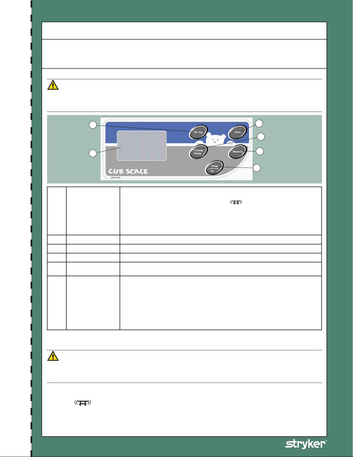
CUB Crib - FL19
D
C
E
A
B
F
Utilisation de la balance
La balance permet d’obtenir une lecture du poids du patient en livres (lb) ou en kilogrammes (kg) avec une précision
de ± 0,5 lb (0,2 kg) à 50 lbs (22 kg) ou moins et ± 1,0 lbs (0,4 kg) à ≥ 50 lbs (22 kg) quand plat. Cette lecture peut
être conservée en mémoire. Le système permet aussi d’ajouter ou d’enlever un appareil ou un accessoire de la
civière sans en retirer le patient.
MODULE DE COMMANDE DE LA BALANCE
MISE EN GARDE
• Afin d’éviter d’endommager les composants électroniques de la balance, ne vous appuyez pas sur le support d’accessoires abritant
le module de commande de la balance.
• N’utilisez pas de tige à soluté fixe à deux ou trois étages au pied d’une civière munie de la balance.
Active la balance. Une pesée s’effectue dès que cette touche est pressée et relâchée. Un
poids s’affiche à l’écran quatre à dix secondes plus tard. Aucun poids n’est cependant affiché
si l’icône « Error - Ex.x » ou l’icône de mouvement
Weigh/On
A
(Peser/Marche)
Memory (Mémoire) Mise en mémoire du résultat de la pesée ou rappel à l’écran du poids enregistré en mémoire.
B
Zero (Remise à zéro) Mise à zéro du poids affiché à l’écran et du poids enregistré en mémoire.
C
lb / kg Changer d’unité de mesure (lb ou kg).
D
Change Equipment
E
(Modifier le matériel)
Écran de la balance
F
UTILISATION DE LA BALANCE
MISE EN GARDE
Détachez ici Détachez ici
La zone de pesée de la balance comprend toute la partie supérieure de la civière, incluant les côtés de sûreté, les supports d’accessoires,
les crochets pour sac de drainage, les supports à dossier (en option) et porte-moniteur (en option) situés sous le sommier. Lors d’une
pesée ou d’une mise à zéro, assurez-vous qu’aucun objet extérieur n’est en contact avec la civière.
l’erreur ou stabiliser la civière avant d’utiliser la balance à nouveau (voir la Liste des codes
d’erreur du Manuel d’entretien).
REMARQUE
La balance ne fonctionne pas en mode continu. Celle-ci doit être activée en pressant la touche
Weigh/On (Peser/Marche) chaque fois qu’une lecture du poids du patient est requise.
Retirer ou ajouter de l’équipement à la civière sans en retirer le patient.
La balance se mettra hors fonction après 30 secondes d’inactivité, sauf pendant l’opération
d’ajout/retrait d’équipement, où le délai est de trois minutes. Elle peut être réactivée simplement
en pressant la touche Weigh/On (Peser/Marche).
Si le patient pèse plus de 54 kg, le message « Error - E05 » apparaîtra à l’écran pour indiquer
que la balance ne doit pas être utilisée dans ces conditions, car sa capacité maximale de
pesée est dépassée.
D’autres messages d’erreur sont susceptibles d’apparaître à l’écran lors de l’utilisation de la
balance. Référez-vous à la Liste des codes d’erreur du Manuel d’entretien afin de comprendre
leur signification et les mesures à prendre lorsqu’ils apparaissent.
apparaît à l’écran. Il faudra corriger
Guide de référence du lit CUB Crib
REMARQUE
• L’icône
d’effectuer une lecture du poids du patient parce que la civière est instable. Stabilisez la civière puis répétez l’opération en cours.
• Les touches Memory (Mémoire), Change Equipment (Modifier le matériel) et Zero (Remise à zéro) peuvent être utilisées pour
interrompre le processus de lecture du poids lorsque l’opération désirée ne nécessite pas l’affichage d’un poids.
Numéro de pièce : 1900-069-001 Rev A.0
Consulter le Manuel d’utilisation pour de plus amples informations.
peut apparaître à n’importe quel moment de l’utilisation de la balance. Il indique que la balance est incapable
Page 85

CUB Crib - Model FL19
Utilisation de la balance (Suite)
A. PRÉPARATION (MISE À ZÉRO) DE LA BALANCE POUR UN NOUVEAU PATIENT
• Préparez la civière pour le nouveau patient (draps, oreillers, équipement, etc.).
• Pressez/relâchez la touche Weigh/On (Peser/Marche) pour activer la balance. Une lecture de poids apparaîtra à l’écran
après 4 à 10 secondes d’attente durant lesquelles une ligne de trois traits d’union clignotera.
•
Pressez et maintenez enfoncée la touche Zero (Remise à zéro) pendant au moins deux secondes. Relâchez la touche de
4 à 10 secondes plus tard, le poids affiché et celui mis en mémoire seront ramenés à zéro.
•
Installez le patient dans la civière et pressez/relâchez la touche Weigh/On (Peser/Marche). Le poids du patient s’affichera
4 à 10 secondes plus tard.
MISE EN GARDE
Afin de maintenir la précision de la balance, il est recommandé de la remettre à zéro au moins une fois par semaine. Notez que le patient
devra être retiré de la civière avant de mettre la balance à zéro.
B. ENREGISTREMENT EN MÉMOIRE D’UNE LECTURE DE POIDS
• Pressez/relâchez la touche Weigh/On (Peser/Marche) pour activer la balance. Attendez l’affichage du poids à l’écran.
• Pressez et maintenez enfoncée pendant deux secondes la touche Memory (Mémoire). Dès que le message « Memory »
apparaît à l’écran, relâchez la touche. Le poids lu précédemment est maintenant mis en mémoire.
C. RAPPEL À L’ÉCRAN DU POIDS ENREGISTRÉ EN MÉMOIRE
• Pressez/relâchez la touche Weigh/On (Peser/Marche) pour activer la balance. Passez directement à l’étape suivante
sans attendre l’affichage du poids.
• Pressez la touche Memory (Mémoire). « Memory » apparaîtra à l’écran, tout comme la valeur enregistrée en mémoire.
Pour sortir du mode Memory (Mémoire), pressez/relâchez de nouveau la touche Weigh/On (Peser/Marche).
D. MISE À ZÉRO DU POIDS AFFICHÉ À L’ÉCRAN ET DU POIDS ENREGISTRÉ EN MÉMOIRE
• Pressez la touche Weigh/On (Peser/Marche) pour activer la balance. Passez directement à l’étape suivante sans
attendre l’affichage du poids.
• Pressez et maintenez enfoncée la touche Zero (Remise à zéro) pendant au moins deux secondes. Relâchez la touche
de 4 à 10 secondes plus tard, le poids affiché et celui mis en mémoire seront ramenés à zéro.
E. MISE À ZÉRO DE LA MÉMOIRE SEULEMENT
• Pressez la touche Weigh/On (Peser/Marche) pour activer la balance. Passez directement à l’étape suivante sans
attendre l’affichage du poids.
• Pressez simultanément et maintenez enfoncées pendant au moins deux secondes les touches Memory (Mémoire) et
Zero (Remise à zéro). Relâchez les touches. L’écran affichera 0.0 lb/kg.
F. AJOUT OU RETRAIT D’ÉQUIPEMENT AVEC UN PATIENT DANS LA CIVIÈRE
• Pressez la touche Weigh/On (Peser/Marche) pour activer la balance. Vous pouvez passer immédiatement à la prochaine
étape, mais si vous désirez comparer le poids résultant de la procédure d’ajout/retrait d’équipement avec le poids du
patient avant la procédure, laissez le processus suivre son cours jusqu’à l’affichage du poids et notez ce poids.
• Pressez la touche Change Equipment (Modifier le matériel). Quatre à dix secondes plus tard, le message « Change
Equipment » apparaîtra à l’écran. REMARQUE : La balance s’éteindra automatiquement si cette étape prend plus de
trois minutes à s’accomplir; il faudra alors reprendre l’opération depuis le début.
•
Ajoutez ou retirez l’équipement de la civière. Puis, pressez de nouveau la touche Change Equipment
Quatre à dix secondes plus tard, le poids du patient inchangé réapparaîtra à l’écran.
(Modifier le matériel).
Détachez ici Détachez ici
REMARQUE
Afin d’éviter de fausser la lecture du poids d’un patient, le mode Change Equipment (Modifier le matériel) doit être utilisé chaque fois
qu’un objet, quel qu’il soit, est ajouté à la zone de pesée de la balance ou retiré de celle-ci. Advenant le cas où un objet aurait été
prématurément (sans la procédure d’ajout/retrait d’équipement) ajouté à une civière occupée par un patient ou retiré de celle-ci, il
Guide de référence du lit CUB Crib
faudra impérativement mettre la balance à zéro (voir la procédure A à la page 19) après avoir retiré le patient de la civière.
G. CHANGEMENT D’UNITÉ DE MESURE DU POIDS
• Pressez la touche Weigh/On (Peser/Marche) pour activer la balance. Une lecture de poids apparaîtra à l’écran après
4 à 10 secondes d’attente.
• Pressez la touche lb / kg pour passer de livres (lb) à kilogrammes (kg), ou l’inverse.
• La touche lb / kg peut être rendue inopérante afin de prévenir son activation par inadvertance. Pour ce faire, pressez et
maintenez enfoncées pendant au moins deux secondes les touches lb / kg et Memory (Mémoire). Faites de même pour
rendre de nouveau accessible la touche lb / kg.
Les informations présentées dans ce guide de référence rapide est destiné à démontrer un produit Stryker. Toujours se référer à la notice, étiquette
du produit et / ou manuel des opérations avant d’utiliser tout produit Stryker. Les produits peuvent ne pas être disponibles dans tous les marchés.
Certaines caractéristiques indiquées dans ce guide de référence rapide sont les options et ne peut être configuré sur tous les produits. La
disponibilité des produits est soumise aux pratiques de réglementation ou médicaux qui régissent les marchés individuels. S’il vous plaît contacter
votre Account Manager Stryker si vous avez des questions concernant la disponibilité des produits Stryker dans votre région.
Les produits référencés avec la désignation ™ sont des marques déposées de Stryker.
Les produits référencés avec la désignation ® sont des marques déposées de Stryker.
Numéro de pièce : 1900-069-001 Rev A.0
Consulter le Manuel d’utilisation pour de plus amples informations.
Page 86

Aperçu des Caractéristiques
E
F
A
A
D B C
D
B
C
COMMANDES DE LA BASE
CUB Crib - FL19
Deux types de modèle de base sont offerts : à hauteur fixe
et à hauteur variable (hydraulique).
Pompez pour lever le sommier.
A
Appuyez au centre de la pédale (B) pour abaisser
B
les deux extrémités de la civière simultanément.
Appuyez sur le côté de la pédale (B) le plus près
C
de la tête de la civière pour abaisser le côté tête.
Appuyez sur le côté de la pédale (B) le plus près
D
du pied de la civière pour abaisser le côté pied.
Fonctions Brake (Frein) et Steer (Direction) (côté
E
gauche).
Fonctions Steer (Direction) et Brake (Frein) (côté
F
droit).
DROITE
RIGHT
LEFT
GAUCHE
Commandes de la base
CÔTÉ TÊTE
HEAD END
FONCTIONNEMENT DES FREINS
AVERTISSEMENT
• Appliquez toujours les freins lorsqu’un patient est retiré ou placé dans la civière.
• Laissez toujours les freins en fonction à moins que la civière ne soit déplacée. Après avoir appliqué les freins, poussez
sur la civière afin de vous assurer qu’elle est bien immobilisée.
• Une civière instable peut causer des blessures graves au patient lorsqu’il est installé sur la civière ou retiré de celle-ci.
• Si les freins ne fonctionnent pas correctement, référez-vous à la procédure de réglage des freins du manuel d’entretien.
ÉLÉVATION / DESCENTE DU SOMMIER (EN OPTION) - FL19H SEULEMENT
TRENDELENBURG / TRENDELENBURG INVERSÉ (EN OPTION) - FL19H SEULEMENT
AVERTISSEMENT
Afin d’éviter les blessures au patient et/ou à l’utilisateur,
assurez-vous, avant de baisser le sommier ou de le
placer en l’une des positions Trendelenburg, que les
côtés de sûreté sont complètement relevés et qu’aucun
équipement ni personne ne se trouve près du sommier ou
sous celle-ci.
Assurez-vous de déplacer tout équipement pouvant
nuire à la descente ou à l’élévation de la civière.
• Pour lever le sommier, pompez la pédale (A)
sans arrêt jusqu’à ce que la hauteur désirée
soit atteinte.
Détachez ici Détachez ici
• Pour baisser les deux extrémités du sommier en
même temps, pressez le centre de la pédale
(B) jusqu’à la hauteur désirée. Pour baisser
uniquement la tête du sommier, pressez le côté
de la pédale (B) le plus près du côté tête. Pour
baisser uniquement le pied du sommier, pressez
le côté de la pédale (B) le plus près du côté pied.
REMARQUE
Le sommier doit d’abord être monté pour obtenir
une position Trendelenburg.
AVERTISSEMENT
Afin d’éviter les blessures au patient et/ou à l’utilisateur,
assurez-vous, avant de baisser le sommier ou de le
placer en l’une des positions Trendelenburg, que
les côtés de sûreté sont complètement relevés et
qu’aucun équipement ni personne ne se trouve près
du sommier ou sous celle-ci.
• Pour la position Trendelenburg (tête en bas),
pressez le côté de la pédale (B) le plus près de
la tête de la civière.
• Pour la position Trendelenburg inversé (pied en
bas), pressez le côté de la pédale (B) le plus
près du pied de la civière.
Guide de référence du lit CUB Crib
Numéro de pièce : 1900-069-001 Rev A.0
Consulter le Manuel d’utilisation pour de plus amples informations.
Page 87
CUB Crib - Model FL19
AVERTISSEMENT
• Afin d’assurer un environnement sécuritaire au patient, le personnel hospitalier s’assurera que les composants de la civière (côtés de sûreté, portes
d’accès, accessoires, etc.) sont en bon état et fonctionnent correctement avant d’installer un patient dans la civière.
• Appliquez toujours les freins lorsqu’un patient est retiré ou placé dans la civière.
• Laissez toujours les freins en fonction à moins que la civière ne soit déplacée. Après avoir appliqué les freins, poussez sur la civière afin de vous assurer
qu’elle est bien immobilisée.
• Une civière instable peut causer des blessures graves au patient lorsqu’il est installé sur la civière ou retiré de celle-ci.
• Si les freins ne fonctionnent pas correctement, référez-vous à la procédure de réglage des freins du manuel d’entretien.
• Assurez-vous d’appliquer les freins aux quatre roulettes pour une immobilisation complète de la civière à hauteur fixe.
• Lorsqu’une immobilisation complète de la civière à hauteur fixe est requise, assurez-vous d’activer le mécanisme de blocage des quatre roulettes de
la civière.
• Afin de réduire les risques de blessure, placez le sommier en position horizontale et au plus bas et relevez complètement les côtés de sûreté lorsqu’un
patient est déplacé avec la civière.
• Les côtés de sûreté doivent toujours être maintenus en position haute et le sommier en position basse sauf lorsque le patient est soigné. Ne laissez
jamais un patient sans surveillance lorsque les côtés de sûreté sont abaissés.
• Assurez-vous que des politiques appropriées sont mises en place pour assurer la sécurité du patient lorsqu’une tige à soluté ou une bouteille d’oxygène
est utilisée. Le patient ne doit pas y avoir accès ni les manipuler.
• Afin de prévenir tout risque d’incendie, n’activez pas la balance lorsqu’une tente à oxygène est utilisée sur une civière munie de la balance (en option).
De plus, assurez-vous que les côtés de sûreté sont à l’extérieur de la tente.
• Afin d’éviter les blessures au patient et/ou à l’utilisateur, assurez-vous, avant de baisser le sommier ou de le placer en l’une des positions Trendelenburg,
que les côtés de sûreté sont complètement relevés et qu’aucun équipement ni personne ne se trouve près du sommier ou sous celle-ci.
• Afin d’éviter les blessures au patient et/ou à l’utilisateur ou d’endommager la civière, ne tentez pas de déplacer la civière de côté lorsque le mode
directionnel est activé. La 5e roue directionnelle ne pivote pas.
• Afin d’éviter les chutes et les blessures, assurez-vous que les côtés de sûreté et les portes d’accès sont bien verrouillés après les avoir manipulés ou
avant de laisser un patient sans surveillance.
• Afin d’éviter les chutes et les blessures, assurez-vous que les deux indicateurs d’ouverture/fermeture (situés sur les boutons de déverrouillage) de la
porte d’accès sont tous deux de couleur verte lorsque la porte est fermée et verrouillée.
• Afin d’éviter toute blessure au patient, assurez-vous que ses membres ne sont pas à proximité des parties mobiles d’un côté de sûreté qui doit être
relevé ou baissé. Assurez-vous que le côté de sûreté est bien verrouillé après l’avoir manipulé.
• Afin d’éviter les blessures au patient et/ou à l’utilisateur ou d’endommager la civière, ne déplacez pas la civière en utilisant une porte d’accès ou la
poignée d’un côté de sûreté.
• Évitez de vous servir d’une porte d’accès ou d’une main courante comme dispositif de poussée ou de traction, car cela risque d’endommager la civière
ou de blesser le patient.
• Afin d’éviter les blessures au patient et/ou à l’utilisateur ou d’endommager la civière, ne tentez pas de déplacer la civière de côté lorsque le mode
directionnel est activé. La 5e roue directionnelle ne pivote pas.
• Afin d’éviter toute blessure au patient, assurez-vous qu’il repose en toute sécurité dans la civière avant de manipuler la section de tête ou de pied ou
de baisser un côté de sûreté.
• Afin d’éviter toute blessure au patient, assurez-vous que le patient repose en toute sécurité dans le sommier avant de manipuler la section de tête ou
de pied ou d’abaisser un côté de sûreté.
• Afin d’éviter toute blessure au patient, assurez-vous que les membres du patient ne sont pas à proximité des parties mobiles d’un côté de sûreté qui
doit être relevé ou abaissé. Assurez-vous que le côté de sûreté est bien verrouillé après l’avoir manipulé.
• N’utilisez plus la civière lorsque le patient est capable d’en sortir sans aide ou qu’il a atteint la grandeur de 90 cm.
• Ne mettez pas dans la civière, ou à proximité de celle-ci, des cordons, courroies ou objets semblables susceptibles de s’enrouler autour du cou du
patient.
• Ne laissez aucun objet ou jouet dans la civière.
• N’utilisez pas de matelas d’eau avec cette civière.
• Afin d’éviter toute blessure lorsque la section de tête manuelle ou la section de pied du sommier est élevée ou abaissée, assurez-vous que le support
est bien engagé dans les arrêts de support avant de relâcher la section de tête ou de pied.
• Afin d’éviter les blessures au patient, tout matelas utilisé dans cette civière doit mesurer au moins 146,05 cm de longueur par 74,6 cm de largeur, et
son épaisseur ne doit pas être inférieure à 7,6 cm ni dépasser 15,3 cm.
• Négliger de nettoyer correctement les matelas ou de retirer du service les matelas défectueux accroît le risque d’exposition aux substances pathogènes
susceptibles de causer des infections chez le patient ou l’utilisateur.
• N’utilisez pas la civière si des pièces y manquent ou sont brisées. Adressez-vous à votre vendeur autorisé ou à Stryker pour obtenir des pièces de
rechange. N’utilisez que des pièces de rechange d’origine fournies par Stryker.
• Capacité de charge statique maximale = 181,4 kg.
• Retirez le patient du lit avant d’entreprendre l’installation de l’accessoire.
• Si la civière qui recevra le toit de protection est équipée du dispositif de pesée (en option), assurez-vous de le fermer avant d’entreprendre l’installation
du toit. Une fois l’installation terminée, référez-vous au Guide de l’utilisateur de la civière pour mettre la balance à zéro.
• Assurez-vous, pour la sécurité du patient, que les extrémités des deux traverses inférieures sont correctement verrouillées avant de laisser le patient
sans surveillance.
• Afin d’éviter des blessures aux mains et /ou aux doigts, n’utilisez jamais les bras latéraux articulés du toit pour le refermer. Manipuler toujours le toit
par le centre de la traverse inférieure.
• Il est très important pour la sécurité du patient que l’ensemble est soigneusement inspecté avant son utilisation afin de s’assurer qu’elle est correctement
et solidement fixés.
Guide de référence du lit CUB Crib
Détachez ici Détachez ici
MISE EN GARDE
• Le poids des sacs de soluté ne doit pas dépasser 18 kg.
• N’utilisez pas de tige à soluté fixe à deux ou trois étages au pied d’une civière munie de la balance.
• Afin d’éviter d’endommager les composants électroniques de la balance, ne vous appuyez pas sur le support d’accessoires abritant le module de
commande de la balance.
• N’utilisez pas de tige à soluté fixe à deux ou trois étages au pied d’une civière munie de la balance.
• La zone de pesée de la balance comprend toute la partie supérieure de la civière, incluant les côtés de sûreté, les supports d’accessoires, les crochets
pour sac de drainage, les supports à dossier (en option) et porte-moniteur (en option) situés sous le sommier. Lors d’une pesée ou d’une mise à zéro,
assurez-vous qu’aucun objet extérieur n’est en contact avec la civière.
• Afin de maintenir la précision de la balance, il est recommandé de la remettre à zéro au moins une fois par semaine. Notez que le patient devra être
retiré de la civière avant de mettre la balance à zéro.
• N’utilisez que des batteries alcalines 1,5 V. L’utilisation de batteries autres que celles spécifiées risque d’endommager les composants électroniques
de la balance.
• Retirez les batteries de leur emplacement lorsque la balance ou la civière ne sont pas utilisés pendant de longues périodes.
• N’utilisez que des batteries alcalines 1,5 V. L’utilisation de batteries autres que celles spécifiées risque d’endommager les composants électroniques
de la balance.
• Retirez les batteries de leur emplacement lorsque la balance ou la civière ne sont pas utilisés pendant de longues périodes.
• Rangez toujours un bras d’attache non utilisé afin d’éviter de l’endommager lorsque la civière est déplacée.
• Avant d’utiliser le toit de protection, il est très important pour la sécurité du patient de s’assurer, par un examen minutieux, que le toit a été correctement
installé sur la civière.
• N’utilisez pas le toit de protection pour déplacer la civière.
Numéro de pièce : 1900-069-001 Rev A.0
Consulter le Manuel d’utilisation pour de plus amples informations.
Page 88

Page 89

Stryker Medical
3800 E. Centre Avenue
Portage, MI 49002
USA
2014/10 1900-009-001 REV B www.stryker.com
 Loading...