

Page 1

Booms and Lights
Installation and Service Manual
July 2011 1004-400-061 REV YB www.stryker.com
Page 2

Page 3

Stryker Booms and Lights
Installation and Service Manual
is manual contains condential information that shall not be disclosed or duplicated for any reason other than to use and maintain a
Stryker Booms and Lights. is restriction does not limit the right to use information contained in this manual, if it is obtained from another source without restriction. e information subject to this restriction is contained in all pages of this manual.
© June 2011 Stryker Communications. All rights reserved. Information in this document is subject to change without notice. Stryker,
Stryker logo, Visum®, and StrykeCam® 2 are registered trademarks of Stryker
All rights reserved.
Stryker Booms and Lights Installation and Service Manual
1004-400-061 REV YB
Page 4

Page 5

S
Contents
1. Warnings and Cautions ........................................................................................................................................ 10
1.1 Safeguards and Precautions............................................................................................... 10
1.2 Warnings .......................................................................................................................... 10
2. Product Symbol Denition .................................................................................................................................. 11
3. Tool List ............................................................................................................................................................... 13
3.1 Required Tools .................................................................................................................. 13
3.2 Optional Tools ................................................................................................................... 13
4. Unpacking ........................................................................................................................................................... 14
4.1 Halogen Light ................................................................................................................... 14
4.1.1 Suspension Box .........................................................................................................14
4.1.2 Accessory Box ...........................................................................................................14
4.1.3 Light Head Boxes ......................................................................................................14
4.2 LED Light .......................................................................................................................... 15
4.2.1 Suspension Box .........................................................................................................16
4.2.2 Accessory Box ...........................................................................................................16
4.2.3 Light Head Boxes 1 and 2 ...........................................................................................16
4.3 Flat Panel Arms ................................................................................................................ 17
4.4 Booms .............................................................................................................................. 17
5. Preparing the Mounting (Interface) Plate............................................................................................................ 18
6. Preparing the Suspensions .................................................................................................................................. 19
6.1 Installing the Cable Kit for Lights ....................................................................................... 19
6.2 Surgical Lights .................................................................................................................. 20
6.2.1 Standard Horizontal Arm ...........................................................................................20
6.2.2 Extended Horizontal Arm...........................................................................................20
6.2.3 Alternate Light Installation Instructions.....................................................................21
6.3 Flat Panel ......................................................................................................................... 22
6.4 Booms .............................................................................................................................. 22
6.5 Routing Cables .................................................................................................................. 24
7. Installing the Suspension and Boom Arms .......................................................................................................... 25
7.1 Alternate Light Installation Instructions (Continued) ........................................................... 26
5
Page 6

S
8. Installing Light Heads ......................................................................................................................................... 27
8.1 LED and Halogen ............................................................................................................... 27
8.1.1 Standard Light ..........................................................................................................27
8.1.2 Low Ceiling Light ......................................................................................................28
9. Powering the System .......................................................................................................................................... 31
9.1 Halogen Lights .................................................................................................................. 31
9.1.1 Electrical and Data Connections .................................................................................31
9.2 LED Lights ......................................................................................................................... 32
9.2.1 Power Supply Box Wall Mount (Optional) ....................................................................32
9.3 Power Supply Box Connections ........................................................................................... 33
9.3.1 Power ......................................................................................................................34
9.3.2 Control .....................................................................................................................34
9.3.3 Wall Control Unit Port ...............................................................................................35
9.3.4 SORN ........................................................................................................................35
9.3.5 SIDNE .......................................................................................................................35
9.3.6 Expansion Port (Optional) ..........................................................................................35
9.4 Visum LED New Installation Setup ...................................................................................... 36
9.4.1 Required Tools ..........................................................................................................36
9.4.2 Installing USB to RS-232 Adapter (for laptops without Serial Ports) ..............................36
9.4.3 Connecting a Laptop to the SIDNE Port on Visum LED System .......................................37
9.4.4 Visum LED Main Menu ...............................................................................................39
9.4.5 New Installation .......................................................................................................39
10. Monitor Assembly ............................................................................................................................................. 40
10.1 Light Flat Panel or Single Panel installation ....................................................................... 40
10.2 Adjusting the Yoke ............................................................................................................ 41
10.2.1 Adjusting the Width ..................................................................................................41
10.2.2 Adjusting the Height .................................................................................................45
10.3 Attaching the Monitor ....................................................................................................... 46
10.4 Balancing the Monitor ....................................................................................................... 48
10.5 Adjusting the Brakes ......................................................................................................... 50
11. Boom Shelf Attachment and Adjusting Brakes/Stops ....................................................................................... 51
11.1 Boom Shelf and Accessories Attachment ............................................................................. 51
11.1.1 FLEXiS Shelf Installation ............................................................................................51
6
Page 7

S
11.1.2 FLEXiS Handle to MFR Bracket Installation ..................................................................54
11.1.3 FLEXiS Handle to Service Head Installation .................................................................56
11.1.4 Installing Auxiliary Plates ..........................................................................................58
11.1.5 Installing Other Accessories .......................................................................................59
11.1.6 Installing GCX Accessory Track on OSC600 Down Tube ...................................................59
11.1.7 Drawer Installation ...................................................................................................59
11.2 Lights and Flat Panel Arms ................................................................................................. 60
11.2.1 Height Adjustment ...................................................................................................60
11.2.2 Tension Adjustment ..................................................................................................62
11.2.3 Adjusting the Friction Brakes .....................................................................................62
11.2.4 Adjusting the Brake Force of the Extension and Spring Arms ........................................64
11.2.5 Adjusting Down Tube Screws ......................................................................................64
11.3 Adjusting the Cardanic Suspension .................................................................................... 66
11.4 Boom Arms ....................................................................................................................... 67
11.4.1 OSC400 .....................................................................................................................67
11.4.2 OSC600 .....................................................................................................................70
12. Installing Covers ................................................................................................................................................ 72
12.1 Lights and Flat Panel Suspension ....................................................................................... 72
12.2 Booms .............................................................................................................................. 72
12.3 Tandem ............................................................................................................................ 73
12.4 Cable Covers ...................................................................................................................... 75
12.4.1 Flat Panel/Light/Light Suspension .............................................................................75
12.4.2 Light/Flat Panel Suspension - Teacup Installation .......................................................75
12.4.3 MMP200, OSC400, and OSC600 ...................................................................................76
12.4.4 Mounting Motor Ring Covers ......................................................................................77
12.4.5 Replacing Rear End Spring Arm Covers ........................................................................77
12.5 Installing a Flexstrip Kit (Dual Flat Panel Arm Only) ............................................................. 78
13. Accessories ........................................................................................................................................................ 79
13.1 Lights ............................................................................................................................... 79
13.1.1 Halogen In-Light Camera and Weighted Light Handle Assemblies ................................79
13.1.2 LED In-Light Camera and Weighted Light Handle Assemblies .......................................79
13.1.3 Field Upgrade for StrykeCam In-Light Camera .............................................................79
13.1.4 Power Supply Box Components .................................................................................81
13.1.5 Camera Installation ..................................................................................................82
7
Page 8

S
14. Legacy ............................................................................................................................................................... 84
14.1 Suspension Installation ..................................................................................................... 84
14.2 Installing Spring Arms (if necessary for lights only suspension) ............................................ 84
14.3 Standard Width Yoke ......................................................................................................... 87
14.4 Halogen Light Flat Panel Stop Replacement ........................................................................ 87
14.5 Variant ............................................................................................................................. 89
14.6 Installing GCX Accessory Track on OSC400 Service Head ........................................................ 89
15. Cleaning and Completion .................................................................................................................................. 93
16. Servicing the Visum 600/450 ............................................................................................................................. 94
16.1 Electronic Control System .................................................................................................. 94
16.2 Power Supply Box ............................................................................................................. 96
16.2.1 Halogen Power Supply Box Troubleshooting Guide ......................................................96
16.3 Wall Control ..................................................................................................................... 99
16.4 Plug Layout of the Electronic Control System .................................................................... 101
16.5 Plug Allocation ............................................................................................................... 101
16.5.1 Location of the Plug and Diagnostic LEDs on the Terminal ..........................................102
16.5.2 Plug Allocation Operating Console and Diagnostic LEDs .............................................103
16.5.3 Plug Locations of the Power Box ..............................................................................103
16.5.4 Connections at the front: ......................................................................................... 104
16.5.5 Connections at the back: .........................................................................................105
16.5.6 Connection Structure of Systems ..............................................................................107
16.6 Can Bus Troubleshooting ................................................................................................. 110
16.6.1 Light Block Diagram ................................................................................................ 110
17. Servicing Booms .............................................................................................................................................. 114
17.1 System operation ........................................................................................................... 114
17.2 Troubleshooting ............................................................................................................. 114
17.2.1 Air Leaks .................................................................................................................115
17.3 Miscellaneous Hardware Parts List ................................................................................... 117
17.4 Replacing the Trim Strip .................................................................................................. 119
17.5 Replacing Med Gas .......................................................................................................... 120
17.5.1 Replacing a Nitrogen Regulator ...............................................................................120
17.5.2 Replacing Med Gas Plate..........................................................................................120
8
Page 9

S
17.6 Replacing the Brake Bladder ............................................................................................ 121
17.7 Reassembling the Service Head ........................................................................................ 127
17.7.1 Removing and Attaching the Front and Back Plates ...................................................127
17.7.2 Removing and Attaching the MFR ............................................................................128
17.7.3 Removing Extrusions ...............................................................................................129
17.7.4 Installing Extrusions ...............................................................................................129
17.7.5 Removing Modules .................................................................................................130
17.7.6 Installing Modules ..................................................................................................132
17.8 Replacing the Motor ........................................................................................................ 133
17.9 Electro-Pneumatic (EP) Module ........................................................................................ 135
17.9.1 Removing the Electro-Pneumatic (EP) Module ..........................................................135
17.9.2 Installing an Electro-Pneumatic (EP) Module ............................................................135
17.10 Generation 1 Service Head ............................................................................................... 136
17.10.1 Replacing a Shelf with Brake ...................................................................................136
17.10.2 Replacing the Brake Button ..................................................................................... 138
18. Servicing the LED ............................................................................................................................................ 140
19. Replacement Part Numbers ............................................................................................................................. 141
20. Contact Information ........................................................................................................................................ 144
9
Page 10

S
1. Warnings and Cautions
Please read this manual and follow its instructions carefully. The words WARNING, CAUTION, and
Note carry special meanings and should be carefully reviewed:
Warning e personal safety of service personnel may be involved. Disregarding
this information could result in injury to the patient.
Caution Special service procedures or precautions must be followed to avoid dam-
aging the equipment.
Warning A warning with a lightening bolt warns of hazardous voltage. All service
must be performed by authorized personnel.
Note Special information to make maintenance easier or important information more
clear.
1.1 Safeguards and Precautions
Stryker trained personnel are the only personnel authorized to install the equipment described in this
manual.
Incorrect operation or negligence of safety measures may cause damage to the equipment, bodily injury or death. oroughly read this manual before use.
• Do not add additional weight to the surgical lights.
• Do not place anything over the surgical lights.
• Do not look directly into the surgical light while powered on.
1.2 Warnings
1. Be a qualied/trained installer for this equipment.
2. Test this equipment prior to release for use by hospital personnel.
3. Disconnect the unit from the electric outlet before inspecting or servicing system components.
Note that more than one electrical supply may be used. Disconnect all power sources before
inspecting.
4. e electrical installation of the operating room must comply with any applicable IEC, CEC,
NEC requirements as well as the local codes and pre-installation manual.
Caution Carefully unpack the unit and check to ensure that no damage occurred
during shipment. If damage has occurred, please contact Stryker Communications.
10
Page 11
2. Product Symbol Denition
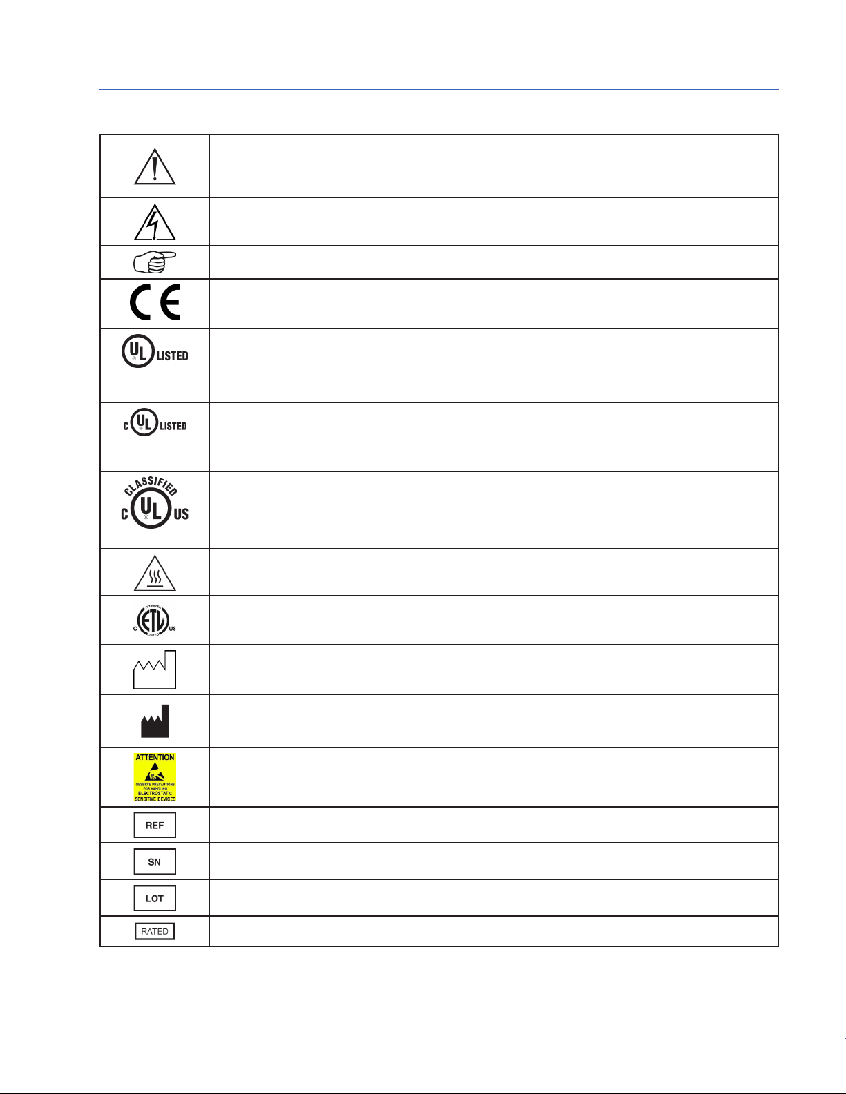
e following symbols may be found on the Stryker Booms and Lights equipment:
An exclamation mark within a triangle is intended to alert the user to the presence
of important operating and maintenance (service) instructions in the literature accompanying the product.
A lightning bolt within a triangle indicates the presence of hazardous voltage. Refer
all service to authorized personnel.
Denotes usage tips and useful information.
Denotes compliance to European Community Directive 93-42-EEC.
Indicates the product is compliant “Medical Electrical Equipment with Respect to
Electrical Shock, Fire, and Mechanical Hazard only in accordance with UL60601-1.
EDS
(29AZ)
Indicates the product is compliant “Medical Electrical Equipment with Respect to
EDS
(29AZ)
(13PZ)
Electrical Shock, Fire, and Mechanical Hazard only in accordance with CAN/CSA
C22.2 No601.1.
Indicates the product is compliant “Medical Electrical Equipment with Respect to
Electrical Shock, Fire, and Mechanical Hazard only in accordance with UL60601-1,
CAN/CSA C22.2 No601.1.
Indicates hot surfaces.
S
Denotes compliance to CSA Standard C22.2, 60601.1 - M90, AS 3200, IEC 60601,
IEC 60601-2-41, UL 60601, EN 60601
Denotes the date the equipment was manufactured.
Denotes the manufacturer of the device.
A yellow box with a hand within a triangle is intended to warn the user of the presence of an electrostatic sensitive device. Follow ESD prevention procedures.
Denotes product/part number.
Denotes product/serial number.
Denotes lot or batch number.
e acceptable wattage input range for this product.
11
Page 12

S
In accordance with European Community Directive 2002/96/EC on Waste Electrical and Electronic Equipment, this symbol indicates that the product must not be
disposed of as unsorted municipal waste but should be collected separately.
Note: e device does not contain any hazardous materials.
Legal regulations may include specications regarding the disposal of this product. We request that you contact Stryker when you plan to withdraw this device
from service for discard.
12
Page 13

3. Tool List
3.1 Required Tools
• Genie li or equipment li, SLC-12 or equivalent
• Torpedo level
• Metric allen set (Shortened 3mm)
• Small and large phillips head
• Small and Large at head screwdriver
• 24mm (15/16 inch) wrench
• Snap ring plier (adjustable to 15mm)
• Torque Wrench (in. lbs.)
• Torque Wrench (. lbs.)
3.2 Optional Tools
• Porta band saw
• Large hand le
• 1/2 inch Drill/Driver
• Tape measure
• Drill bit set
• Hand tool pouch
• Adjustable wrench
• Roofer’s square
S
13
Page 14

S
4. Unpacking
4.1 Halogen Light
Warning Use caution when liing heavy objects to avoid serious bodily injury or
damage to the equipment.
e equipment will arrive in shipping boxes on two separate pallets and may be arranged as depicted
in the images below. e shipping boxes should contain all the necessary components required to install the halogen light system. Use the image and list below to determine where each component of the
light suspension is packaged.
Down Tubes
Suspension
Suspension
Pallet
Ceiling
Covers
4.1.1 Suspension Box
• Light Suspension
• Suspension (Single, Dual, or Triple)
• Spring Arms
• Installation Hardware
• Flat Panel Cable Kit
Accessory Box
Light Head
Light Head
Light Head
Light Head
Pallet
4.1.2 Accessory Box
• Wall Control Unit and Cable Kits
• Power Supply Box
4.1.3 Light Head Boxes
• Halogen light heads
• Light Handle Assemblies
• StrykeCam® In-Light Camera (if purchased)
• Sterilizable Light Handle
• Sterilizable Camera Handle (if StrykeCam was ordered)
If any parts are missing, contact the Shipping and Receiving Department to verify whether a shipping
box(es) was le behind. If all boxes were delivered and parts are unaccounted for, call and inform your
Project Manager of the missing items.
14
Page 15

S
Use box cutters to open the shipping box along the seams.
Note Notice that the boxes have “break away” panels to allow easy access to the parts.
Verify that all parts are present and visibly undamaged.
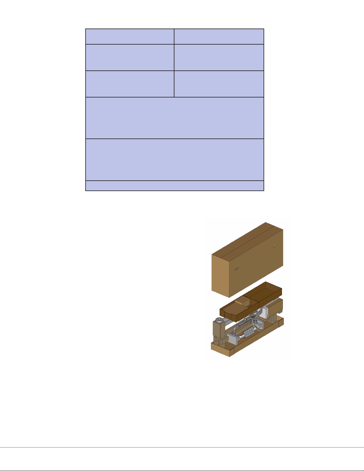
4.2 LED Light
Warning Use caution when liing heavy objects to avoid serious bodily injury or
damage to the equipment.
e equipment will arrive in shipping boxes and may be arranged as depicted in the image below. e
shipping boxes should contain all the necessary components required to install the Visum® LED light
system. Use the image and list below to determine where each component of the light suspension is
packaged.
Light Head Light Head
Light Head Light Head
Suspension Accessory Box
Suspension Accessory Box
Pallet
*e outlined boxes represent a double shipment of supplies.
Orientation of packaging may arrive dierently.
15
Page 16
S
Accessory Box Accessory Box
Light Head Light Head
Light Head Light Head
Suspension
Suspension
Pallet
4.2.1 Suspension Box
• Light Suspension
• Suspension (Single, Dual, or Triple)
• Spring Arms
• Installation Hardware
• Flat Panel Cable Kit
• Tea Cup (EHA only)
4.2.2 Accessory Box
(ere are three boxes within the Accessory Box)
• Ceiling Cover (Box 1)
• Wall Control Unit and Light Cable Kits
(Box 2)
• Power Supply Box and Bezel (Box 3)
• Down Tub e
Extended Horizontal Arm Packaging
4.2.3 Light Head Boxes 1 and 2
• LED light heads
• Light Handle Assemblies
• StrykeCam® 2 In-Light Camera (if purchased)
• Sterilizable Light Handle
• Sterilizable Camera Handle (if StrykeCam 2 was ordered)
16
Page 17

S
If any parts are missing, contact the Shipping and Receiving Department to verify whether a shipping
box(es) was le behind. If all boxes were delivered and parts are unaccounted for, call and inform your
Project Manager of the missing items.
Use box cutters to open the shipping box along the seams.
Note Notice that the boxes have “break away” panels to allow easy access to the parts.
Verify that all parts are present and visibly undamaged.
4.3 Flat Panel Arms
e equipment will arrive in a shipping box on one pallet. e shipping box should contain the Flat
Panel Arm System and Ceiling Covers.
e Flat Panel Arm will be fully assembled and completely wired out of the crate. Uncrate pallet and
open the shipping box.
Use box cutters to open the shipping box along the seams.
Verify that all parts are present and visibly undamaged.
4.4 Booms
Each Boom will arrive in a shipping box on one pallet. e shipping box should contain a Boom Arm,
Service Head, shelves (if applicable), and Ceiling Covers.
Use box cutters to open the shipping box along the seams.
Verify that all parts are present and visibly undamaged.
17
Page 18
S
5. Preparing the Mounting (Interface) Plate
Remove the hardware bag from the suspension box.
Note Ensure all-thread rods do not interfere with the application of ceiling cover by
performing a dry t. e all-thread rods should not extend below the base of the
cover. If they do, cut the rods back.
1. Install six hex nuts below Mounting (Interface) Plate to align ange top approximately even with the bottom of nished ceiling.
2. Use a Torpedo Level to verify that the nuts
are level. Measure two sets at a time.
3. Place at washers and Plastic Isolation Discs (required in Europe) below each hex nut to hold in
place.
Note Plastic Isolation Discs are only required in Europe.
Caution No more than 8 inches of exposed all-thread rod is allowed between the Pre-
installation Plate and the down tube ange for Seismic considerations. No
more than 2 inches of exposed all-thread rod is allowed for Zone 4 installations.
Cover Size
180 mm (7 inches) 153 mm (6 inches)
80 mm (3 inches) 64 mm (2.5 inches)
18
Page 19
S
6. Preparing the Suspensions
6.1 Installing the Cable Kit for Lights
1. Route the power and control cables between the power supply box and the suspension structure.
Verify that the light connectors remain near the ceiling plate, as shown in the gure below.
2. (For LED only) Route the S-Video cable through the pre-installed conduit between the super
structure and video output location.
Note Consult your Project Engineer and/or room drawings to determine the video
output location.
3. Pull the cable between the wall control unit and the power supply box.
One end of the wall control unit cable is unterminated.
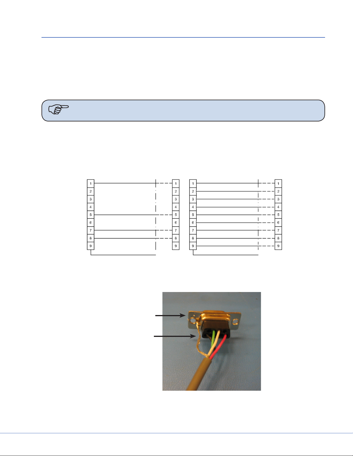
4. Cut the wall control unit cable to length and terminate it. Connect the wires into the female
connector according to the schematic chart shown below.
P1 P2
RED
BLK
WHT
GRN
SHLD
Schematic
P1 P2
SHLD
Schematic
Wall Control Unit Cable Pin Conguration - LED (le) Halogen (right)
5. Solder the Shield Conductor to the DB9 female connector chassis as shown below.
DB9 Female
Connector
Shield Conductor
Soldered Shield Conductor
19
Page 20
S
6.2 Surgical Lights
6.2.1 Standard Horizontal Arm
1. Load the suspension shipping box onto a heavy machinery li device.
2. Cut cardboard 9 inches from the top of the box to facilitate hanging suspension. Be careful not
to cut cables or scratch the suspension.
3. Mount down tube onto suspension. Use the six at head socket cap screws (taped to down tube)
to attach the down tube to the central axis spindle. Tighten all screws with a torque wrench set
to 100 lb-in (8.33 lb-, 11.3 Nm). Once all screws have been tightened, retighten each screw to
ensure correct torque is set.
If you are installing a at panel along with a dual light suspension, verify that the at panel cable
kit is routed through the opening in the down tube.
4. Position the suspension assembly directly below the mount site.
5. Go to Section 7, “Installing the Suspension” to complete installation.
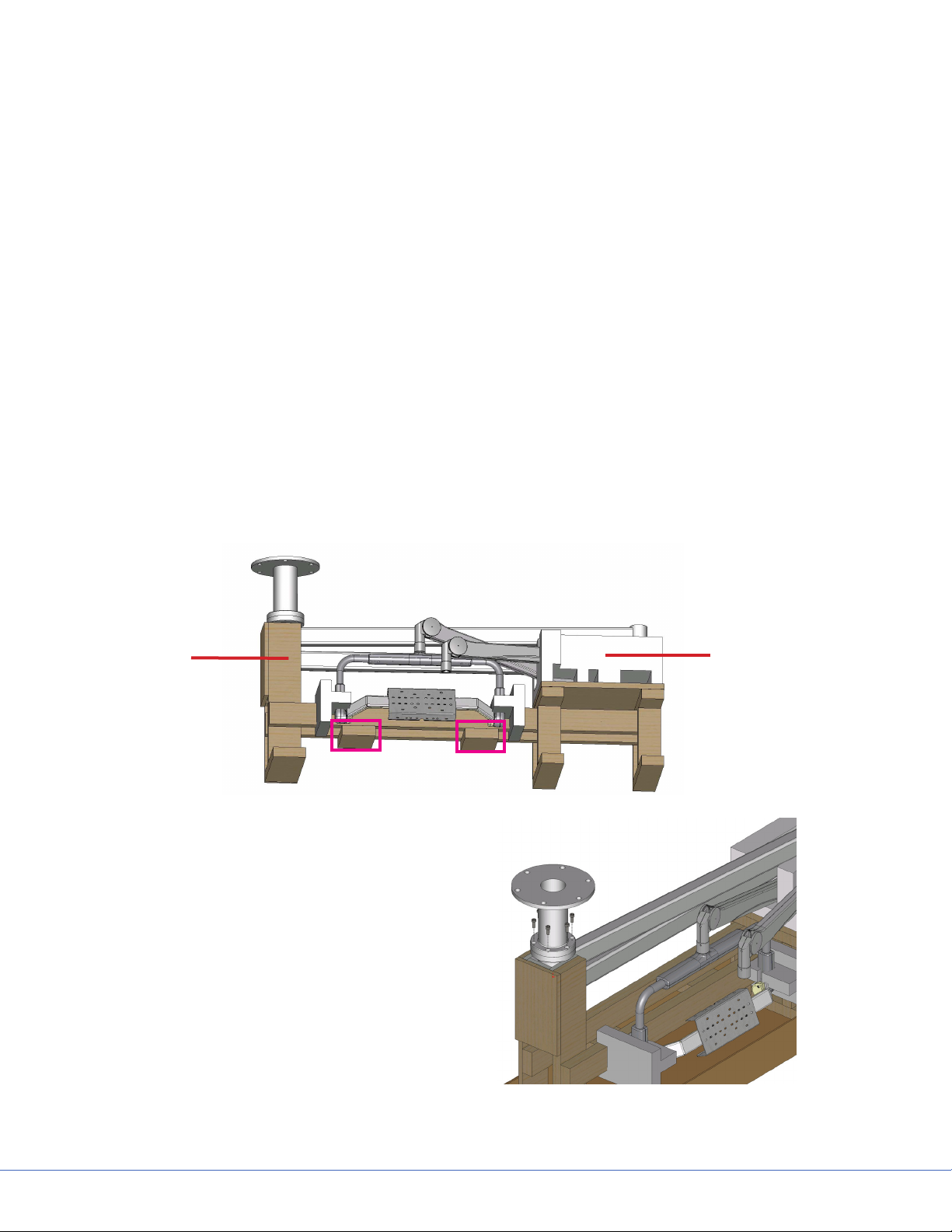
6.2.2 Extended Horizontal Arm
1. Remove all accessories and the cardboard box.
2. Position Genie Life so that forks are underneath the highlighted areas shown in the following
gure.
Brown
packaging is
wood
3. Mount down tube onto suspension. Use
the six socket cap screws to attach the
down tube to the central axis spindle.
Tighten all screws with a torque wrench
set to 354 lb-in (29.5 lb-, 40 N-m). Once
all screws have been tightened, retighten
each screw to ensure correct torque is set.
If you are installing a at panel along with
a dual light suspension, verify that the at
panel cable kit is routed through the opening in the down tube.
White
packaging is
styrofoam
4. Position the suspension assembly directly
below the mount site.
20
Page 21

S
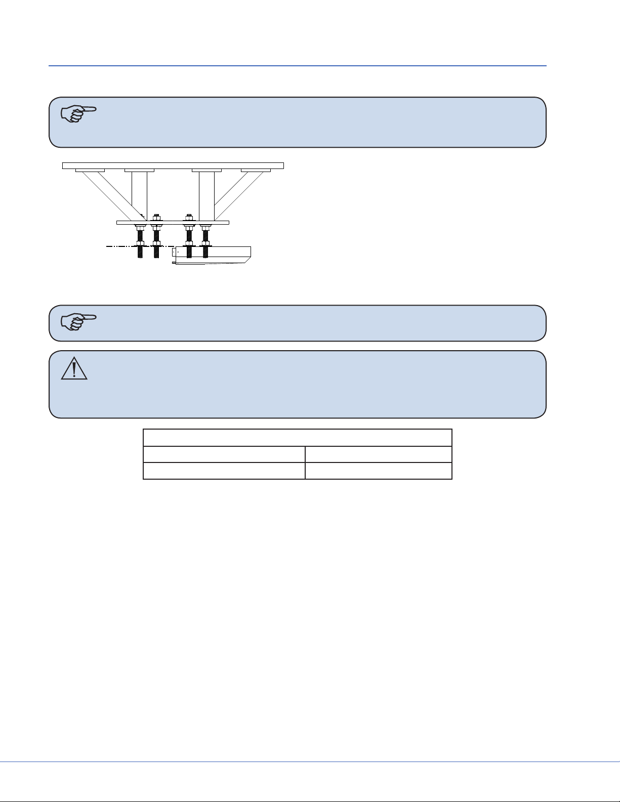
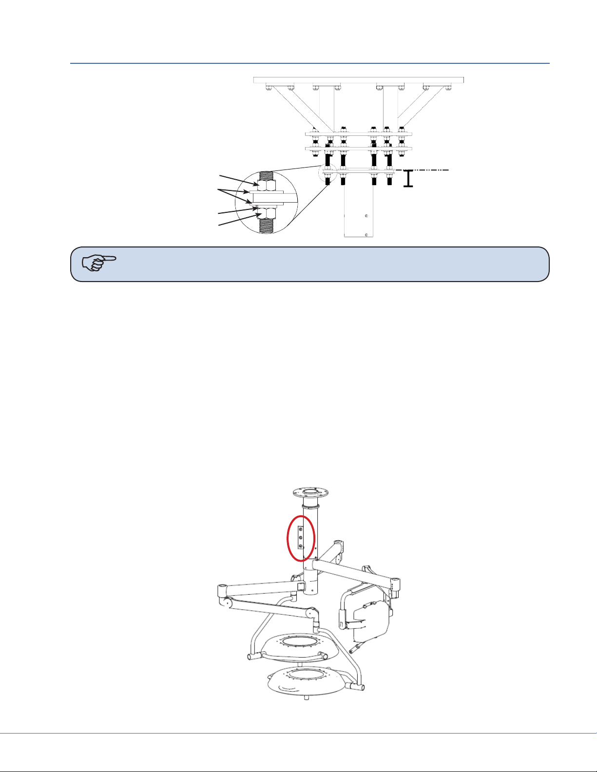
6.2.3 Alternate Light Installation Instructions
1. Load the suspension shipping box onto a heavy machinery li device.
2. Cut cardboard 9 inches from the top of the box to facilitate hanging suspension. Be careful not
to cut cables or scratch the suspension.
Hex Nut
Flat Washer
Lock Washer
Hex Nut
Note When necessary, Plastic Isolation Discs surround the mounting plate, but are only
required in Europe.
3. Raise the down tube toward the mount site.
4. Guide the all-thread rods through the holes located on the down tube ange.
e down tube ange must press lightly against the hardware assembly.
5. Place a at washer on alternating all-thread rods followed by a hex nut; tighten the hex nut.
6. Use a Torpedo Level to verify the down tube ange is level across three horizontal planes. If the
ange is not level, adjust the hex nuts until the Torpedo Level indicates the down tube ange
is level across three horizontal planes. Conrm that the down tube is also level by placing the
Torpedo Level on the down tube at three, evenly-spaced locations.
7. Install a at washer, lock washer, and hex nut on the remaining all-thread rods.
Note Plastic Isolation Discs are only required in Europe.
8. Tighten the hex nuts to 75 -lbs. Ensure the lock washers are fully compressed.
9. Remove the hex nuts from the all-thread rods applied in step 5 and install a lock washer and hex
nut.
21
Page 22
S
10. Use a Torpedo Level to verify that the down tube ange is level across three horizontal planes.
11. Connect the ground wire (found on the down tube ange) to the ground lug located in the ceiling.
12. Refer to Section 7 to complete installation.
6.3 Flat Panel
1. Place the suspension onto a heavy machinery li device.
2. Use zip ties to tie the horizontal arm and
Spring Arm together to prevent swinging
during installation.
3. Raise the Flat Panel Arm for installation;
position the arm so the stop is in the specied location (the Project Manager should
have this information).
Note e normal stop position is above the bed, allowing 330° of rotation of the upper
arm, with the 30° “dead” spot.
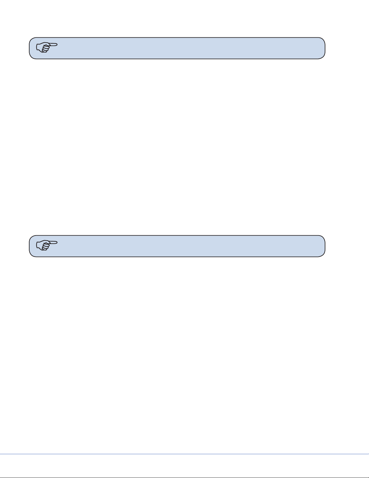
6.4 Booms
Due to door entry height, the ange and drop tube may be removed for entry into the room. e
ange and drop tube must be reinstalled before installation of the equipment boom.
If the MMP200/OSC600 Service Head is not assembled:
1. Place pallet securely on material li (e.g.,
Genie Li).
2. Determine the orientation of the service head before attaching to the down
tube, feel for the notch. e notch will be
mounted to the front of the service Head.
22
Page 23

Shelf End
S
3. Remove the four Allen screws from the
Service Head using a 5mm Allen wrench.
4. Locate the cable kit end and pass through
the service head opening.
MMP200 only
Note e Shelf Wedge kit has a
thick and a thin component.
Orientation of the thin side
towards the front of the service head is important.
0682-001-345 Wedge Kit
If the OSC400 Service Head is not assembled:
5. Verify which Wedge is the thinner wedge
of the 2 halves of the Wedge Kit
6. Place the thinner Wedge towards the front
of the Service Head
7. Place the thicker Wedge towards the rear
of the Service Head.
8. Connect Service Head to articulating arm.
9. Tighten the four Allen screws to 14.75 lb-
(20 Nm) using a 5mm Allen wrench.
10. s
23
Page 24

S
1. Remove the six (6) Allen screws from the
Service Head using a 5mm Allen wrench.
2. Remove the cylinder cover located on the
Down Tube. e two (2) halves can be detached by depressing on the two (2) clips
with a at edge tool.
3. Rotate the Down Tube and determine the
stop location. is point will be installed
to the front of the service head.
4. Locate the cable kit end and pass through the service head opening. In some cases, half of the
pass-thru plate will need to be removed to feed the cable kit completely through.
Caution Be sure to leave enough slack for the EP Module control cable within the
arm set. Failure to do so may result in damage to the cable upon removal
of the EP module.
5. Attach the service head by inserting and tightening the six (6) Allen screws to 7.4 lb- (10 Nm)
using a 5mm Allen wrench.
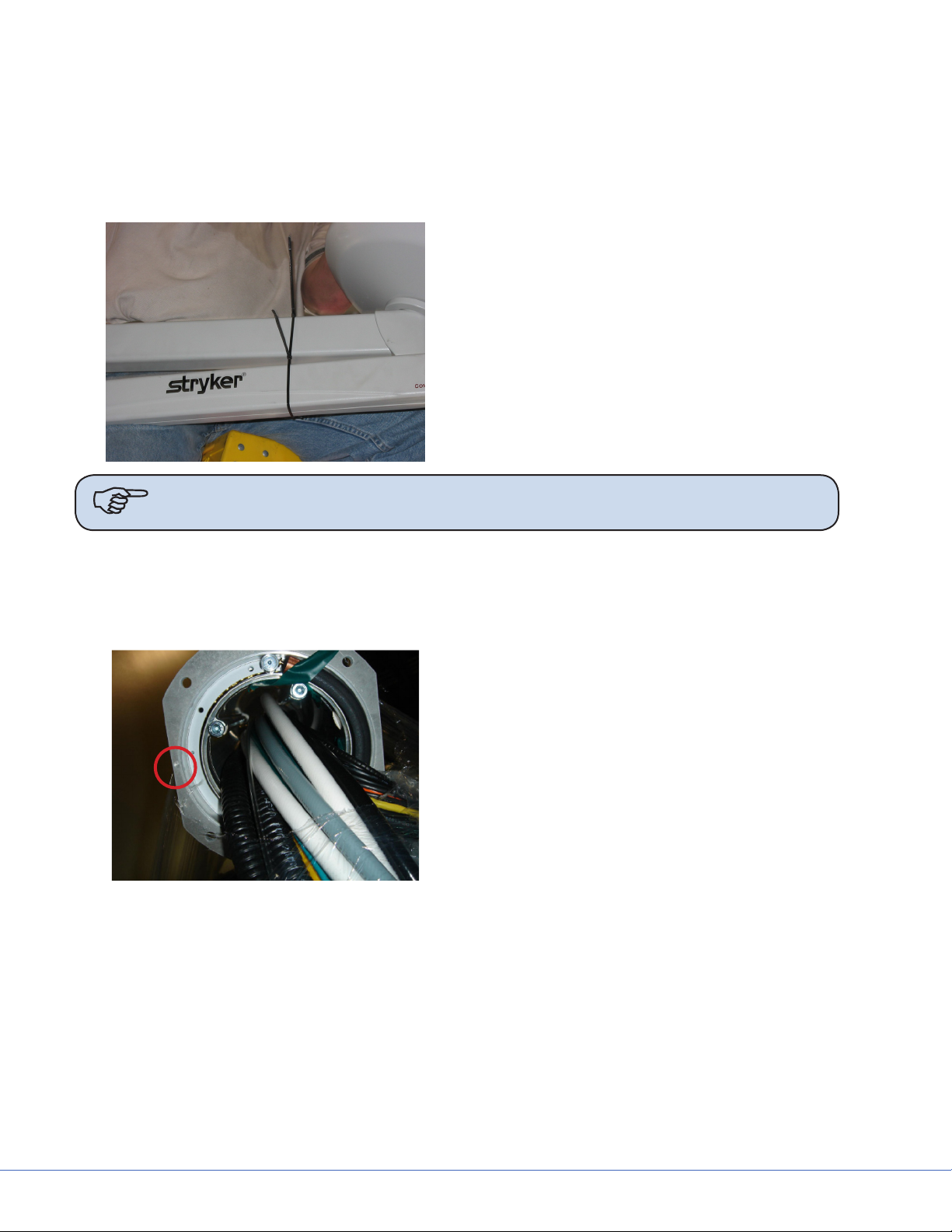
6.5 Routing Cables
is section is only applicable to suspensions with lengthy cable kits.
1. Uncoil the cable kit.
2. Pull the cables from the suspension through the top of the mounting interface plate.
3. Continue to route the cable through the ceiling conduits. Consult your Project Engineer and/or
room drawings to determine cable routing through the conduits.
24
Page 25
S
7. Installing the Suspension and Boom Arms
Hex Nut
Flat Washer
Lock Washer
Hex Nut
Note When necessary, Plastic Isolation Discs surround the mounting plate, but are only
required in Europe.
1. Raise the Suspension assembly toward the mount site.
2. Take care when raising the suspension to prevent pinching cables between the all-thread rods
and down tube.
3. Guide the all-thread rods through the holes located on the down tube ange.
e down tube ange must press lightly against the hardware assembly.
4. Pull all cables and electrical connections through the Mounting (Interface) Plate. If ORIS connectivity is going to occur at a later date, tie-wrap cable kit to down tube ange.
5. Place a at washer on alternating all-thread rods followed by a hex nut; tighten the hex nut.
6. Use a Torpedo Level to verify the down tube ange is level across three horizontal planes. If the
ange is not level, adjust the hex nuts until the Torpedo Level indicates the down tube ange
is level across three horizontal planes. Conrm that the down tube is also level by placing the
Torpedo Level on the down tube at three, evenly-spaced locations.
25
Page 26
S
7. Install a at washer, lock washer, and hex nut on the remaining all-thread rods.
Note Plastic Isolation Discs are only required in Europe.
8. Tighten the hex nuts to 75 -lbs. Ensure the lock washers are fully compressed.
9. Remove the hex nuts from the all-thread rods applied in step 10 and install a lock washer and
hex nut.
10. Use a Torpedo Level to verify that the down tube ange is level across three horizontal planes.
11. Connect the ground wire (found on the down tube ange) to the ground lug located in the ceiling.
12. Lower the li device and check the suspension for stability.
13. Pull excess cable through conduit.
7.1 Alternate Light Installation Instructions (Continued)
1. Using a li device, raise the suspension into the down tube.
2. Pull all cables and electrical connections through the Mounting (Interface) Plate. If ORIS connectivity is going to occur at a later date, tie-wrap cable kit to down tube ange.
3. Pull excess cable through conduit.
4. Mount down tube onto suspension. Use the six at head socket cap screws (taped to down tube)
to attach the down tube to the central axis spindle. Tighten all screws with a torque wrench set
to 100 lb-in (8.33 lb-, 11.3 Nm). Once all screws have been tightened, retighten each screw to
ensure correct torque is set.
Note For EHA - Tighten all screws with a torque wrench set to 354 lb-in (29.5 lb-, 40
N-m).
If you are installing a at panel along with a dual light suspension, verify that the at panel cable
kit is routed through the opening in the down tube.
5. Take care when raising the suspension to prevent pinching cables between the down tube and
suspension.
26
Page 27
S
8. Installing Light Heads
8.1 LED and Halogen
Always install the light heads before installing the light handle assembly and In-Light Camera. e
camera light head must be installed on the uppermost Light Spring Arm.
In the case of LED only, the physical dierence between a 5-pole Spring Arm and a 9-pole Spring Arm
is that the 5-pole slip ring is keyed and the 9-pole slip ring is not. e keys resemble rectangles when
viewed from the end of the slip ring.
Note Two people should li the light head to attach it to the Spring Arm.
Light 1 w/
StrykeCam
Note StrykeCam 2 is always associated with Light 1 and is always installed above Light
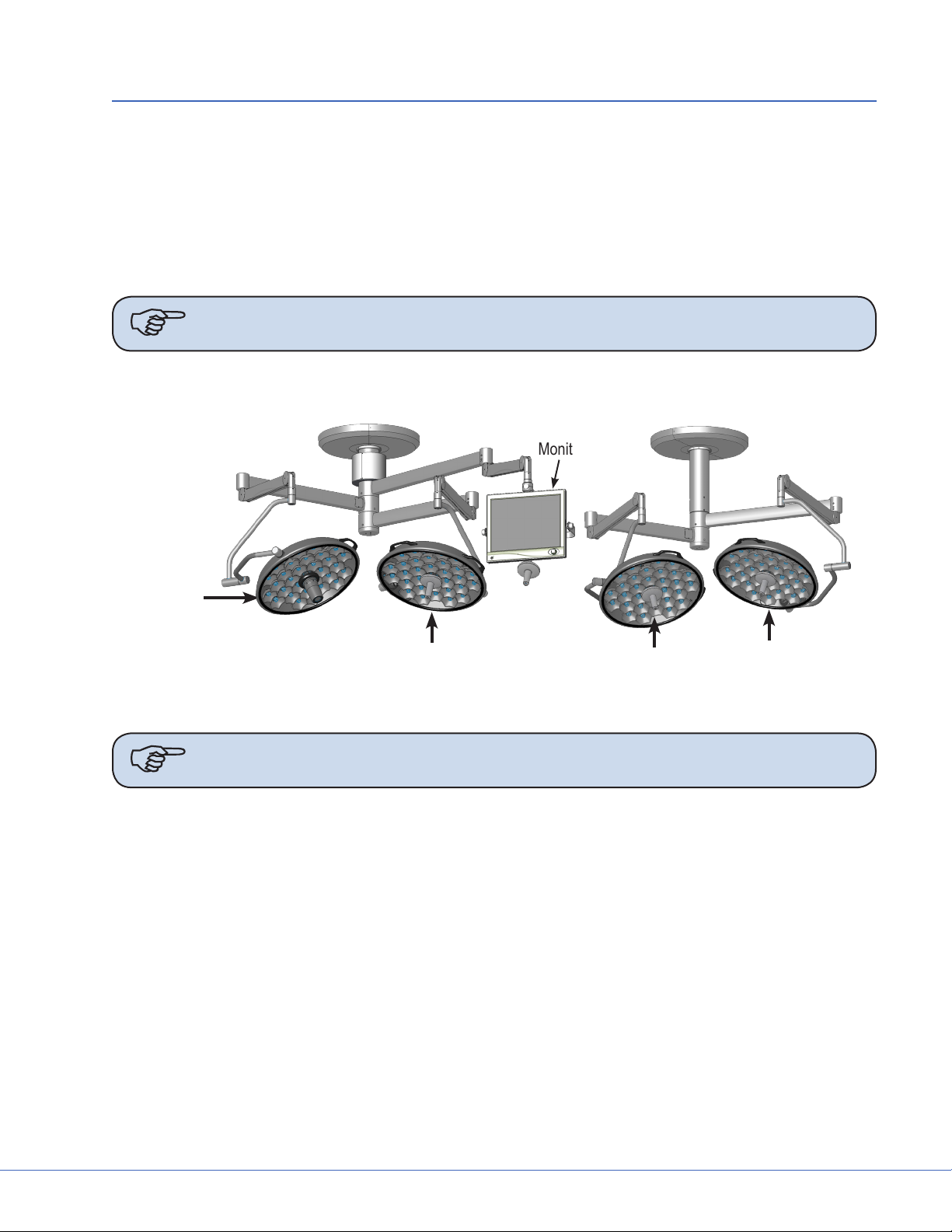
8.1.1 Standard Light
Head 2.
Triple Arm Visum
LED Light Suspension
Light 2
Visum LED Light Suspension
Monitor
Dual Arm Visum LED Light Suspension
Light 4
Light 3
8.1.1.1 5-Pole Light Head
1. Locate the 5-pole Spring Arm and remove the M3 screw.
2. Slide the Safety Segment Cover up to reveal the Safety Segment and re-insert the M3 screw to
hold the cover up.
3. Remove the Safety Segment.
4. Install the 5-pole Light Head.
a. Align the top of the Cardanic Suspension with the bottom of the Spring Arm.
b. Align the rectangle-like keys along the outer wall of the 5-pole slip ring, (located in the light
head) with the notches of the Spring Arm Slip Ring.
c. Raise the light head into the Spring Arm.
5. Reinstall the Safety Segment.
27
Page 28
S
a. Remove the M3 screw and slide the Safety Segment Cover down.
b. Re-insert and tighten the M3 screw to keep the cover in place.
Warning Failure to tighten this screw can cause the Safety Segment Cover to slide
and the light head to fall from the Spring Arm.
8.1.1.2 9-Pole Light Head (LED Only)
1. Locate the 9-pole Spring Arm and remove the M3 screw.
2. Slide the Safety Segment Cover up to reveal the Safety Segment.
3. Remove the Safety Segment.
4. Align the top of the Cardanic Suspension with the bottom of the Spring Arm.
5. Install the 9-pole Light-Head.
Note e 9-pole slip ring is not keyed.
6. Raise the light head into the Spring Arm.
7. Reinstall the Safety Segment.
a. Slide the Safety Segment Cover down.
b. Tighten the M3 screw to keep the cover in place.
Warning Failure to tighten this screw can cause the Safety Segment Cover to slide
and the light head to fall from the Spring Arm.
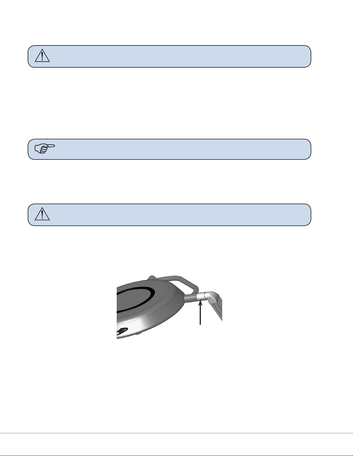
8.1.2 Low Ceiling Light
8.1.2.1 Low Ceiling 5-Pole Light Head
1. Locate the 5-pole Spring Arm and remove the brake screw.
Brake Screw
2. Rotate the cu 90° to reveal the rst retaining screw. Remove the retaining screw from the
Spring Arm.
3. Rotate the cu 180° to reveal the second retaining screw. Remove the retaining screw from the
Spring Arm.
4. Install the 5-pole Light Head.
• Align the rectangle-like keys along the outer wall of the 5-pole slip ring (located in the light
head) with the notches of the Spring Arm slip ring.
28
Page 29

S
• Insert the light head into the Spring Arm. Make sure to support the Spring Arm when assembling.
5. Reinsert the retaining screws removed in steps 2 and 3.
WARNING e cu must be in place before installing the retaining screws.
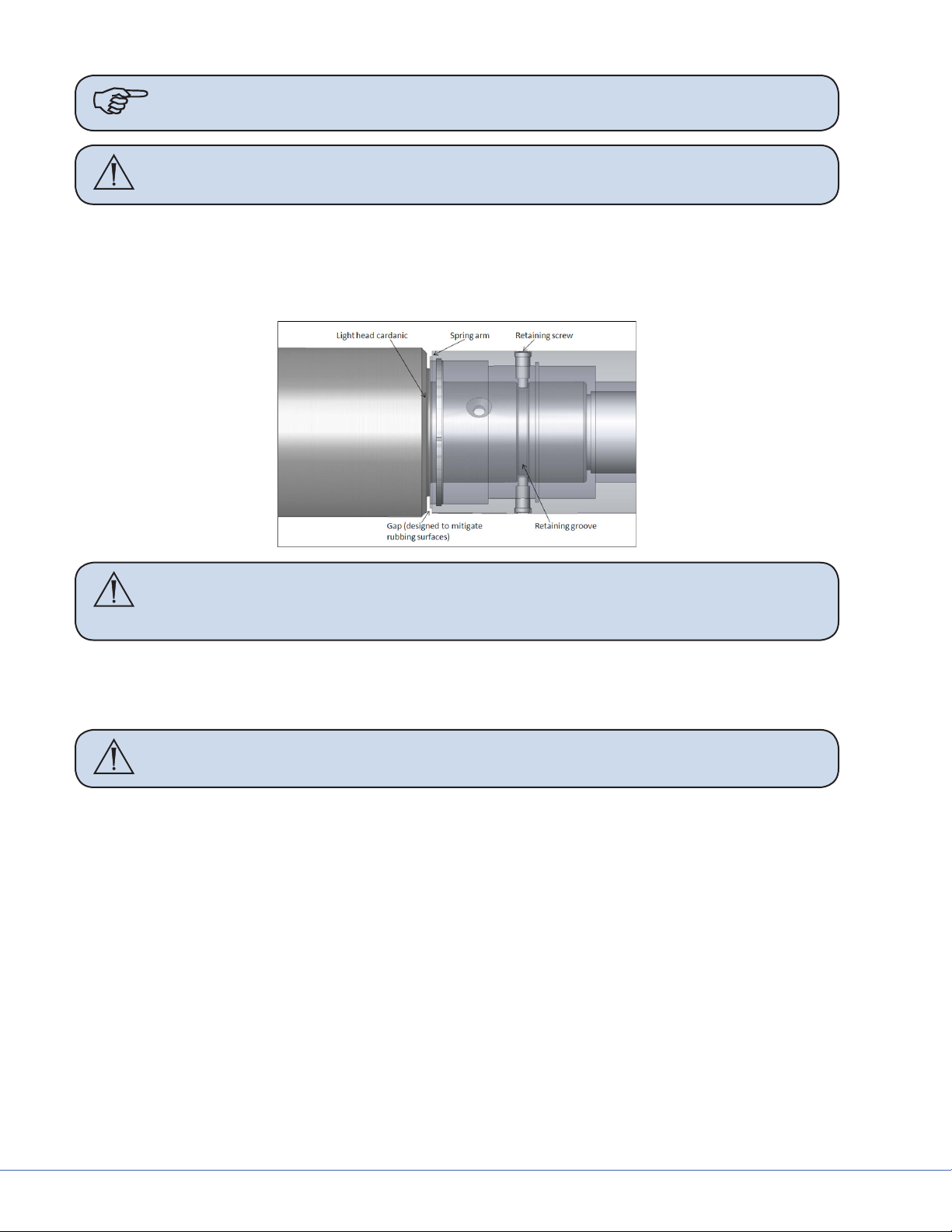
• Align the retaining ring groove feature on the Cardanic of the light head with the retaining
screw holes in the spring arm. A gap will be present between the face of the Cardanic and
face of the spring arm when properly aligned. If needed, back the light head out slightly.
Caution Tightening the retaining screws into the wall of the Cardanic without
aligning them into the retaining ring groove may damage the surface of the
Cardanic.
• Place the rst retaining screw through the opening of the cu and reinstall it. Tighten the
screw completely to ensure that the cu will still rotate freely.
• Rotate the cu 180° to reinstall the second retaining screw. Tighten completely.
Caution Over tightening the Low Ceiling light head to Spring Arm brake screw can
cause permanent damage to the light
• Rotate the cu 90° to insert the brake screw back into place. Tighten the screw until the light
head constantly holds the position in which it is placed.
• When adjusting the brake screw aer installing the light for the rst time or any time aer
performing preventative maintenance, adjust the brake screw and rotate the joint through
a minimum of ve rotations. If aer ve rotations the joint becomes dicult to rotate, the
brake screw is over tightened and needs to be readjusted.
8.1.2.2 Low Ceiling 9-Pole Light Head
1. Locate the 9-pole Spring Arm and remove the brake screw.
2. Rotate the cu 90° to reveal the rst retaining screw. Remove the retaining screw from the
Spring Arm.
3. Rotate the cu 180° to reveal the second retaining screw. Remove the retaining screw from the
Spring Arm.
4. Install the 9-pole light head. Make sure to support the Spring Arm when assembling.
29
Page 30
S
Note e 9-pole slip ring is not keyed.
WARNING e cu must be in place before installing the retaining screws.
5. Reinsert the retaining screws removed in steps 2 and 3.
• Align the retaining ring groove feature on the Cardanic of the light head with the retaining
screw holes in the spring arm. A gap will be present between the face of the Cardanic and
face of the spring arm when properly aligned. If needed, back the light head out slightly.
Caution Tightening the retaining screws into the wall of the Cardanic without
aligning them into the retaining ring groove may damage the surface of the
Cardanic.
• Place the rst retaining screw through the opening of the cu and reinstall it. Tighten the
screw completely to ensure that the cu will still rotate freely.
• Rotate the cu 180° to reinstall the second retaining screw. Tighten completely.
Caution Over tightening the Low Ceiling light head to Spring Arm brake screw can
cause permanent damage to the light
• Rotate the cu 90° to insert the brake screw back into place. Tighten the screw until the light
head constantly holds the position in which it is placed.
• When adjusting the brake screw aer installing the light for the rst time or any time aer
performing preventative maintenance, adjust the brake screw and rotate the joint through
a minimum of ve rotations. If aer ve rotations the joint becomes dicult to rotate, the
brake screw is over tightened and needs to be readjusted.
30
Page 31

9. Powering the System
9.1 Halogen Lights
9.1.1 Electrical and Data Connections
e electrical system consists of the following parts:
• Wall control box
• Power supply box
• Electronics in light head
1. Mount the wall control box into back box and connect the two cables. Top cable is for Light
One (black connector), bottom connection is for Light Two (white connector) and the camera
controls.
2. Place the power supply box
into designated the location
in the documentation station.
e front of the power supply
box has the video connections,
RS-232 connections, and the
low voltage connections to the
lights. e rear has an IEC connector for 115/230VAC power
cord. Additionally a 24VDC
safety power connection is provided for countries with this
requirement.
S
Power Supply Box (Front and Rear View)
Note Proper positioning of the light Power supply box in the Documentation Station
with cable connections in the front.
3. Connect the two cables from the wall control box to the proper connectors.
4. Connect the surgical lighting low voltage and listen for an audible click to conrm proper installation.
5. Connect the data cables to the power supply box.
6. Connect hospital-provided 24 VDC backup power to provided connector (if applicable).
Note Have the hospital designated contractor connect the high voltage cord to the
junction box they installed for Light/ Flat Panel models only. Stryker will not
make high voltage connections. Do not close the circuit breaker yet.
7. Connect low voltage leads from the power supply box to connections at the top of the surgical
lighting suspension.
31
Page 32

S
8. Verify all electrical connections are made, then have contractor turn breaker back on. Power up
the lights using the wall box.
9. Run lights through control, checking the following order:
a. On/o (10 times each light head).
b. Intensity up and down through the full range (10 times per light head).
c. Verify reserve bulb indicator is operational by removing the primary bulb from each light
head. e reserve bulb indicator on the wall control panel should light up. Replace primary
bulb aer turning o the lights.
Caution DO NOT touch the bulb directly with your hands.
9.2 LED Lights
9.2.1 Power Supply Box Wall Mount (Optional)
e power supply box wall mount should be used to securely install and mount a Visum LED power
supply box to a wall.
Mount a standard Hubbell Wiegmann (P/N SC101004) junction box to a wall and then install the
power supply box.
Power
Supply Box
Control
Panel
Note Consult the hospital to determine ideal placement for a power supply box before
mounting the junction box.
Exploded View of
Power Supply Box
Customer Supplied
Back Box*
Wall
Mount
Plate
Vertical Side View of
Power Supply Box
and Back Box
Power Supply Box
Customer
Supplied
Back Box*
*The Back Box is recessed ush within the wall.
Exploded/Side view of Power Supply Box
32
Wall
Page 33

S
9.3 Power Supply Box Connections
Place the power supply box in the designated location in the documentation station.
e front of the power supply box has RS-232 and low voltage connections. e power inlet connector
is located on the rear side of the power supply box for the 115/230VAC power cord.
Light Control
Light Power
Wall
Connection
Port
SORN
Port
SIDNE
Port
Expansion
Power Supply Box, Front View
12.5
(317.5)
Port
Light Control
Light Power
Circuit Breaker
Power Inlet
7.0
(177.8)
Depth 15.5 (393.7)
INCHES (mm)
Power Supply Box, Rear View
Note Avoid blocking the fan exhausts or placing objects within 2 inches of the fan
exhausts.
To control the Visum LED Surgical Light and StrykeCam 2 In-Light Camera from the wall-mounted
control panel, the Light Power Connector and Wall Control Connector must be connected to a power
supply box. Review the sets of instructions and diagrams below for connections.
33
Page 34

S
9.3.1 Power
Light Power
Panel Mount
Light Power
Connector Tabs
Light Power
Connector
Release
Power Supply Box Light Connections
1. Align the Power Connector Tabs
with the slots on the Light Power
Panel Mount.
2. Insert the Power Connector into the
mount and turn it clockwise until
you hear a click.
is ensures that the connection is
secure.
Light Power
Connector
9.3.2 Control
Control Panel
Prongs
Control
Connector
Power Supply Box Control Connections
Control Panel
Mount
Control
Connector
Release
1. Align the prongs on the Control
Panel Mount with the slots on the
Control Connector.
e prongs must t into the slots on
the Control Connector.
2. Insert the Control Connector into
the Control Panel Mount and press
until you hear a click.
is ensures that the connection is
secure.
34
Page 35

9.3.3 Wall Control Unit Port
S
Wall
Control Unit
Port
SORN
Port
SIDNE
Port
Expansion
Port
See the diagram and instructions below to set up
and connect the following ports:
• Wall Control Unit Port
• SORN Port
• SIDNE Port
• Expansion Port
Connection Ports
To enable a connection between the wall-mounted control panel, Visum LED Surgical Lights, and
StrykeCam 2 In-Light Camera, connect the Wall Control Unit Port on the power supply box to the
wall-mounted control panel. Use a Stryker-supplied cable to connect the Wall Control Unit Port to the
Wall Mounted Control Panel.
9.3.4 SORN
SORN is a system that enables device management and networking capability among Stryker equipment. Use an Ethernet or CAT 5e cable to connect the SORN port on the power supply box to a local
hospital network port.
9.3.5 SIDNE
SIDNE is a voice activation platform that enables an operation room and its equipment to be controlled with voice commands. Use a USB A (male) to B (male) cable to connect SIDNE to the power
supply box.
9.3.6 Expansion Port (Optional)
SIDNE can control up to four Visum LED Surgical Lights. To do this, a second power control box is
necessary. Use the Expansion port on the rst power supply box to connect a second power supply box
to control the additional two lights.
To enable SIDNE to control four surgical lights:
1. Connect the
rst power supply box.
2. Insert a second
3. Connect the cable (leading from the Expansion port) to the SIDNE port on the second power
supply box (see diagram below).
USB A to B
USB A to B
cable from an available SIDNE device port to the SIDNE port on the
cable into the Expansion Port on power supply box 1.
35
Page 36

S
Power supply box 1
Connect Power Supply
Box 1 to Power Supply
Box 2 with a USB A to B
cable.
Power supply
box 2
Dual Power Supply Box for Multiple Light Control
Caution Do not connect the SIDNE device port directly to power supply box 2.
4. Connect the power supply box to 110V/230VAC using a medical grade power cord
(included with shipment).
5. Connect the BNC female connectors to the BNC male connectors at the top of the suspension to
establish the S-Video connection.
9.4 Visum LED New Installation Setup
9.4.1 Required Tools
• Laptop with a RS-232 COMM Serial Port
• USB to RS-232 Serial Adapter (0682-400-030; if no Serial Port is present on laptop)
• USB to RS-232 Serial Install Driver
• Visum LED Field Service and Installation Cable (0682-001-691)
• Windows Hyperterminal or other terminal program
9.4.2 Installing USB to RS-232 Adapter (for laptops without Serial Ports)
1. Insert Driver CD.
36
Page 37

S
2. A Driver and User’s Guide window may appear. Close the window. Do not install from this
window.
3. Connect the USB to Serial Adapter. e Found New Hardware Window should open.
4. Select - No, not this time.
5. Click Next.
6. Select - Install from a list of specic location (Advanced). Click Next.
7. Select - Search for the best driver in these locations. Make sure to include the CD-ROM drive by
checking the box that says “Search removable media (oppy, CD-ROM...).” Click Next.
8. Wait while Windows searches for Drivers.
9. Select Appropriate Driver (if using Windows XP/2000 the highlighted driver shown in below).
Make sure to select “usb 2.0 to RS-232 converter.” DO NOT select cable. Click Next.
10. Click Finish.
11. e Found New Hardware Window will appear again. Repeat Steps 4 through 9 once again
selecting the ‘usb 2.0 to RS-232 converter’ and NOT the cable.
12. e USB to RS-232 Serial Adapter is now installed.
9.4.3 Connecting a Laptop to the SIDNE Port on Visum LED System
Note Make sure system is completely connected and fully functional. Failure to do so
may result in improper setup.
1. Insert the USB-B end of the Visum LED Field Service and Installation Cable into the SIDNE
port on the Visum LED power supply box.
2. Insert the DB-9 end of the cable into the Serial port of your laptop (or Serial to USB adapter).
3. Power ON the Visum LED power supply box.
9.4.3.1 Launch Hyperterminal
1. Boot up the laptop and login.
2. Select Windows Start, Programs,
Accessories, Communications, Hyperterminal.
e Connection Description dialog
should display.
3. Enter <VISUM LED> in the Name
eld.
4. Click OK.
e Connect To dialog box displays.
Connection Description Dialog
37
Page 38

S
5. Select a COM Port in the Connect
Using eld and click OK.
A COM Properties Window displays.
Connect To Dialog
6. Select the following options for the
listed elds:
• Bits per second: 19200
• Data bits: 8
• Parity: None
• Stop Bits: 1
• Flow Control: None
7. Click OK.
e Visum LED - HyperTerminal
Screen should display.
COM Properties Dialog
38
Page 39

Visum LED - HyperTerminal Screen
9.4.4 Visum LED Main Menu
S
is screen indicates that a connection has been established between
your laptop and the Visum LED
system.
To view the Main Menu, press “~” on the
laptop keyboard. e Visum LED Main
Menu should display.
e following information can be accessed
from the main menu:
• New Installation
• Service Menu
• View power supply boxCU info
• Test Menu
Visum LED Main Menu
Note Notice that [NOT INSTALLED] displays aer the menu name in the gure above
to indicate the LED Light System has not been installed.
9.4.5 New Installation
To set up a new installation press “0” on your keyboard. e system will prompt you to provide the following information:
• Region Number
• Account Number
• Location of the Installation (room number or operating room number)
• Light Indication: L1 and L2 or L3 and L4.
• Finished Installation, Are you sure ‘y’ or ‘n’ (program is case sensitive)
Note Obtain the Region Number and Account Number from your Project Manager if
this information is unknown to you.
e system completes the installation aer your response to the last inquiry. Enter <x> to exit the
installation.
e installation is successful if the LED lights on the Wall Control Unit are not ashing.
39
Page 40

S
10. Monitor Assembly
10.1 Light Flat Panel or Single Panel installation
16
17
15
14
11
13
12
4
10
3
2
1
5
9
6
8
7
Yoke Anatomy
Part Description Part Description
1 Shroud 10 Central Monitor Support Bracket
2 Shroud Knobs 10. Monitor Vertical Adjust Bracket
3 Monitor Width Adjust Clamp Bottom 12 Handle Assembly
4 Monitor Width Adjust Clamp Top 13 Le Pivot Arm Cable Cover
5 Right Side Support Tube 14 Le Pivot Arm
6 Outer Right Adjust Clamp 15 Inner Le Adjust Clamp
7 Inner Right Adjust Clamp 16 Outer Le Adjust Clamp
8 Right Pivot Arm 17 Le Side Support Tube
9 Right Pivot Arm Cover
40
Page 41

10.2 Adjusting the Yoke
10.2.1 Adjusting the Width
To adjust the width of the yoke:
1. Remove the power supply from the Central Monitor Support Bracket.
2. Remove the cable cover that is concealing the cables on the le Pivot Arm.
Width Adjust Clamp
Left Pivot Arm
Cable Cover
S
Central Monitor
Support
Right Pivot Arm
Cable Cover
Remove the cable cover
Note It is not necessary to remove the cable cover from both Pivot Arms, only the le
side where the cables are concealed.
3. Remove the Central Support Bracket by removing the eight M6 socket head screws and all
washers using a 5mm Allen wrench.
Caution Before beginning to remove the screws holding the Width Adjust Clamp
together, loosely place two cable ties around each side of the clamp to prevent the yoke from falling once the screws have been removed.
41
Page 42

S
Support Straps
Support strap locations
(each yoke will only contain two support straps
even though four are shown in this gure)
4. Remove the eight M5 screws located under
the Width Adjust Clamp using a 4mm Allen wrench, and pull down the clamp.
5. Loosen the support strap inside the Width
Adjust Clamp that is securing the support
tube in place from either the le or the
right side. Do not remove the strap completely.
Note For ease of installation, adjust one side at a time.
6. Yoke width is adjusted by inserting the tube alignment pins into the numbered holes in the
bottom piece of the Width Adjust Clamp. Use Table 10.1 to determine the correct holes for the
monitor, and seat the alignment pins in their respective bracket holes.
Note Measurements presented in the table are estimates only. Adjustments may need
to be made before completing installation to ensure correct balance and t.
7. Secure the horizontal tube to the lower Width Adjust Clamp by tightening the support straps
with self tapping screws until the strap is torqued. Avoid tearing the strap.
WARNING Failure to tighten the support straps could result in the yoke falling.
Note Use the inside strap locations when possible.
8. Repeat steps 5-7 for the opposite side.
9. Reassemble the Width Adjust Clamp and secure using the M5 socket head screws. Tighten all
screws to 35 lb. in. (3.95 Nm) torque.
WARNING Ensure that all screws are present. Missing screws could result in the yoke
falling.
Note Use a torque wrench to tighten screws. If a torque wrench is not available, do not
attempt to tighten screws yourself, but contact your Stryker representative.
42
Page 43

S
3 and 4
Support
Central Monitor
Handle
Adjust Hole
Hole
Depth
Monitor Adjustment
holes
1 and 2
holes
1 and 2
holes
3 and 4
holes
1 and 2
holes
Vertical
Monitor
Adjustment Hole
Table 10.1 - Bracket Adjustments
Height Pin
Placement
5 3 Bottom screws in 8 4 Bottom 2
1 3 Bottom screws in 10 1 Bottom 2
7 7 Bottom screws in 5 1 Top 2 holes 4 and 5
1 1 Top screws in 5 11 Bottom 2
Monitor Width Pin
Stryker Vision
Elect HDTV 26”
43
Elect 21”
Stryker Vision
Radiance 19” 1 3 Bottom screws in 5 3 Bottom 2
Sony LMD 24” 5 3 Bottom screws in 10 3 Bottom 2
Allowable
Configuration
Most Expanded
Configuration
Most Collapsed
Allowable
Page 44

S
13 13
1 15 5811 8 11
Width Adjust Clamp
10. Using Table 10.1 as a guide, reattach the Central Monitor Support to the Pivot Arms using all
eight socket head screws and related washers, ensuring that each Pivot Arm has a least one serrated washer attached for grounding purposes. Be sure to center the Central Support Bracket
within the general assembly. Tighten all screws to 65 lb. in. (7.34 Nm) torque.
WARNING It is necessary to use serrated washers and scratch them through the paint
layer to the actual metal surface to prevent the possibility of electric shock.
1
2
3
4
5
4
3
2
1
1
2
3
4
5
Pivot Arm
Central Monitor Support Bracket
Warning Ensure that all screws are present. Missing screws could result in the yoke
falling.
Note Use Table 10.1 as a guide on how to properly adjust the yoke to account for the
center of gravity. If the center of gravity is improperly balanced, the yoke will not
perform correctly.
44
Page 45

10.2.2 Adjusting the Height
Left Cable Cover
Le cable cover
S
1. Remove the cable cover from the le Pivot
Arm where the cables are concealed.
Note It is not necessary to remove
the cable cover from both
horizontal arm supports,
only the le side where the
cables are concealed.
2. Remove the M5 screws from either the le
or right Height Adjust Clamp. Use care
when removing the screws, as pieces of the
clamp may fall o.
Note For ease of installation,
adjust the height one arm at
a time.
3. Remove the outer piece of the Height Adjust Clamp and remove the tube alignment pin from
the inner piece.
4. Use Table 10.1 to determine the appropriate hole to seat the alignment pin into in the inner
piece of the Height Adjust Clamp.
Note Measurements presented in the table are estimates only. Adjustments may need
to be made before completing installation to ensure correct balance and t.
5. Set the alignment pins in their respective
bracket holes in the inner Height Adjust
Clamp.
6. Reattach the outer Height Adjust Clamp
and secure with M5 socket head screws.
Tighten all screws to 35 lb. in. (3.95 Nm)
torque.
WARNING Ensure that all screws
are present. Missing
screws could result in
the yoke falling.
Height Adjust Clamp
8. Attach the cable cover to the Le Pivot Arm, using three M4 X 12 button head socket cap
screws. Hand tighten all screws fully.
Note Ensure that cables do not get pinched.
45
7. Repeat steps 1-5 for the opposite Height
Adjust Clamp.
Page 46

S
10.3 Attaching the Monitor
1. Attach the power supply to the Central Support Bracket using cable ties. Tighten the cable ties
to prevent movement of the power supply.
2. Ensure that all monitor cables lay at below the power supply and are routed to the right or le.
Caution Take care not to kink the ber optic cable beyond a 5mm bend radius to
prevent damaging it.
WARNING DO NOT OVERLOAD THE ADJUSTABLE YOKE.
Cable Tie Locations
Cable Tie Locations
Cable tie locations
3. Lay the monitor screen side down on a at surface.
Caution If there are knobs that extrude from the surface of the monitor, take care to
ensure that they hang o the edge of the table to prevent them from being
broken or damaged while installing the Monitor Vertical Adjust Bracket.
Caution Take care not to scratch the monitor screen when placing it face down.
4. Align the holes on the Monitor Vertical Adjust Bracket with the VESA mounting holes on the
back of the monitor, using Table 10.1 as a guide. Ensure that the cutout for the handle assembly
is at the bottom of the monitor.
5. Secure the Monitor Vertical Adjust Bracket to the back of the monitor using four M4 socket
head screws, and tighten using a 3mm Allen wrench.
WARNING Ensure that all screws are present. Missing screws could result in the moni-
tor falling.
6. Align and place the handle assembly on the back of the Monitor Vertical Adjust Bracket using
the screw mounting holes. Take care to ensure that the handle assembly does not interfere with
the base of the monitor.
7. Secure the handle assembly to the Monitor Vertical Adjust Bracket using two M5 socket head
screws and washers; tighten to 35 lb. in. (3.95 Nm) torque.
46
Page 47

S
8. From the position shown in the next gure, rotate the Pivot Arms of the support bracket to determine which side is the top to ensure that the monitor is installed right side up. e pivot arm
will rotate 90º in one direction only; the side that rotates up is the top.
Top
Bracket rotations
9. Place the monitor onto the Central Monitor Support Bracket so that the Monitor Vertical Adjust
bracket is seated outside the Central Monitor Support Bracket.
Vertical Adjust
Bracket
Vertical Adjust
Bracket
Central Monitor
Support
Monitor Vertical Adjust Bracket seated outside the Central Monitor Support Bracket
10. Align the safety guide slots on the Monitor Vertical Adjust Bracket with the center-most two
holes on the Central Monitor Support Bracket. Secure the brackets together using four M6
socket head screws, and loosely tighten using a 5mm Allen wrench. Do not tighten screws completely to allow the monitor to slide freely in the safety guides.
11. Tip the monitor up into a vertical position.
12. Slide the monitor backward or forward so that the end of the Monitor Vertical Adjust Bracket
sits ush with the back of the Central Support Bracket, or to provide enough space for the power
supply. Be sure that the handle does not touch the power supply.
13. Align the bracket adjustment holes on both brackets, and secure them together using four M6
socket head screws and serrated washers. Tighten all screws to 65 lb. in. (7.34 Nm) torque.
14. Connect the cables to the monitor.
47
Page 48

S
15. Attach the shroud to the back of the Adjustable Yoke using the four knob screws.
WARNING Ensure that all screws are present. Missing screws could result in the yoke
falling.
10.4 Balancing the Monitor
When the monitor is balanced correctly
and the brakes are properly adjusted, the
yoke will always hold the position in which
it is placed throughout its range of motion.
Improper balance and brake adjustments
10
11
1
2
3
4
5
6
7
8
9
1
2
3
4
5
6
7
8
9
10
may result in the monitor driing when it is
released. e vertical and horizontal adjustments of the yoke center of gravity are
accomplished by changing the position of
the Monitor Vertical Adjust Bracket either
on the back of the monitor, in relation to the
Central Monitor support bracket, or both.
To test balancing and brake adjustment,
move and release the yoke in various positions throughout it’s range of motion. If the
monitor dris in any position, use Table 10.2
to determine where the center of gravity
is located; use Table 10.1 as an adjustment
guide. Note that the yoke’s center of gravity
may require adjustment in both the vertical
and horizontal directions (for example topheavy or bottom-heavy). If the monitor still
continues to dri, tighten the brakes.
1
2
3
4
5
6
7
8
9
10
11
Monitor Vertical Adjust Bracket (see Table 10.1)
48
11
1
2
3
4
5
6
7
8
9
10
Page 49

Table 10.2 - Adjusting the Center of Gravity
Monitor Center of Gravity and Drift Direction Condition
The center of gravity is aligned with the pitch
adjustment joint, and the yoke is balanced. The
monitor does not drift when released from any
position with little brake force.
Problem: Monitor is top-heavy
Solution: Move monitor down on Vertical Adjust
Bracket
S
Problem: Monitor is bottom-heavy
Solution: Move monitor up on Vertical Adjust
Bracket
Problem: Monitor is front-heavy
Solution: Move monitor and Vertical Adjust
Bracket backward on Central Monitor Support
Problem: Monitor is back-heavy
Solution: Move monitor and Vertical Adjust
Bracket forward on Central Monitor Support
If the monitor does not continue to fall forward or backward on its own, it is properly adjusted.
49
Page 50

S
10.5 Adjusting the Brakes
Once the center of gravity has been properly adjusted, you may need to tighten or loosen the tension
on the brakes.
To adjust the brake tension, insert a 3mm Allen
wrench into the socket head screw located on
the underside of the respective height adjust arm
and tighten the screw in a clockwise direction
or loosen in a counterclockwise direction. Only
tighten or loosen the screw slightly to determine
if it is sucient to hold the monitor in place.
Adjust brake screws identically for both sides
at the same time (i.e., turn the right side one
quarter turn, then turn the le side one quarter
turn). Continue to adjust the brakes a little bit at
Brakes
Brake location
a time until they easily hold the monitor in place
throughout it’s range of motion.
50
Page 51

11. Boom Shelf Attachment and Adjusting Brakes/Stops
11.1 Boom Shelf and Accessories Attachment
11.1.1 FLEXiS Shelf Installation
Shelf with handle attached
S
To install a shelf:
1. Remove the shelf from the packaging. e shelf should include all the parts shown in the gure
above, unless it comes without a handle.
2. Assemble the shelf clamps.
a. Combine the clamp pieces as shown in the gure below (Item 1). Use the M8 clamp screw
(Item 2) and clamp nut (Item 3) to loosely assemble the clamps.
b. Assemble the M10 mounting screws (Item 4) through the clamps into the shelf.
1
2
3
2
4
Shelf Assembly
Part Part Name
1 Shelf Clamps
2 M6 Clamp Screws
3 Clamp Nuts
4 M10 Mounting Screws
51
Page 52

S
3. Loosen the mounting screws (Item 2).
4. Loosen the clamp screws (Item 1 in the following gure) as much as possible without disassembly.
2
1
1
Screw and Nut Locations
5. Slide each clamp assembly apart and position the shelf on the MFRs of the FLEXiS System. e
clamps should be able to open enough to directly install the shelf to the desired location. e
shelf can also be attached by sliding the clamps onto the MFRs.
6. If the clamps cannot close properly, the shelf may not be level.
7. Fully tighten the clamp screws (Item 1).
8. Fully tighten the mounting screws (Item 2).
1 2
Location of Screws on Access Panel
9. If the shelf has a handle, connect the control cable from the FLEXiS System to the
connector on the back of the shelf.
a. Using a Phillips screw driver, open the
access panel (Item 1) on the front or
back of the FLEXiS System by removing
the eight Phillips screws (Item 2).
52
Page 53

Tether Wire Location
S
b. e access panel is attached to the
FLEXiS System via a tether wire inside
the system to prevent it from falling
when removed. Ensure the panel rests
on the tether when it is removed and not
1
on the medical gas hoses.
c. Locate the control cable connector in-
side the FLEXiS System.
Control Cable for a Shelf with Handle
Data Pass-rough Location
d. Pass the control cable through the data
pass-through on the same side as the
shelf with handle.
e. Connect the control cable to the shelf
and store cable slack inside the FLEXiS
System.
53
Page 54

S
11.1.2 FLEXiS Handle to MFR Bracket Installation
1
2
Part Part Name
1 Clamps
2 M6 Clamp Screws
3 Clamp Nuts
4 M10 Mounting Screws
2
3
4
Handle Assembly
1. Remove the handle to MFR bracket and handle from the packaging. e handle with bracket
should include all the parts seen in the gure above. e clamps may be disassembled.
2. If the bracket comes with clamps attached skip to Step 5, otherwise assemble the clamps.
a. Combine the clamp pieces as shown in the gure above (Item 1). Use the M8 clamp screws
(Item 2) and clamp nut (Item 3) to loosely combine the clamps.
b. Assemble the M10 mounting screws (Item 4) through the clamps into the handle. Do not
tighten completely
3. Loosen the mounting screws (Item 4).
4. Loosen the clamp screws (Item 2) as much as possible without disassembly.
5. Slide each clamp assembly apart and position the bracket on the MFRs of the FLEXiS System.
e clamps should be able to open enough to directly install the bracket to the desired location.
6. Use a level to ensure the shelf is level.
7. Fully tighten the clamp screws (Item 2).
8. Fully tighten the mounting screws (Item 4).
54
Page 55

S
1 2
Location of Screws on Access Panel
9. Connect the control cable from the FLEXiS System to the connector on the bracket.
a. Using a Phillips screw driver, open the
access panel (Item 1) on the front or
back of the FLEXiS System by removing
the eight Phillips screws (Item 2).
b. Locate the control cable connector in-
side the FLEXiS System. If this handle is
the main control interface of the boom
use the primary (larger) connector.
If this handle is an addition to a shelf
control use the extra cord provided with
the handle and connect to the secondary (smaller) control cable inside the
FLEXiS System.
Primary Control Cable
Secondary Control Cable
55
Page 56

S
Data Pass-rough Location
11.1.3 FLEXiS Handle to Service Head Installation
1. Remove the handle to chassis bracket from
the packaging.
2. Position the handle and bracket under
the FLEXiS System (Item 1) chassis in the
desired location.
3. Install the M3 mounting screws (Item 2)
into the bottom plate of the FLEXiS System.
c. Pass the control cable through the data
pass-through on the same side as the
handle.
d. Connect the control cable to the bracket
and store cable slack inside the FLEXiS
System.
2
1
Handle to FLEXiS Bracket
1 Handle and Bracket
2 M3 Mounting Screws
56
Page 57

S
1 2
Location of Screws on Access Panel
4. Connect the control cable from inside
FLEXiS System to the additional cable
included with the bracket.
a. Using a Phillips screw driver, open the
access panel (Item 1) on the front or
back of the FLEXiS System by removing
the eight Phillips screws (Item 2).
b. Locate the control cable connector in-
side the FLEXiS System.
Secondary Control Cable
Strain Relief Plug Location
c. Remove the strain relief plug from the
bottom of the FLEXiS System by punching it out from the inside of the FLEXiS
using a screw driver or similar tool.
Caution Take care not to dam-
age the service head
when removing the
strain relief plug.
57
Page 58

S
Strain Relief Plug
11.1.4 Installing Auxiliary Plates
d. Pass the small end of the cable provided
with the handle through the strain relief
and into the FLEXiS System.
e. Connect the cable to the secondary con-
trol cable inside the FLEXiS System.
f. Connect the cable to the D-sub connec-
tor on the bracket.
g. Measure the appropriate amount of
slack and install the strain relief plug
around the cable and into the bottom of
the FLEXiS System.
1. Locate a blank plate location to install the
auxiliary plate.
2. Remove the two (2) 6-32 screws that hold
the plate attached to the service head.
ese screws are held in place by either
a grounding bracket with pem nut (side
modules) or metal screw clips (front or
External View Internal View
Screw Clips
WARNING Low voltage plates, medical gas, and video connection plates cannot be
installed in the same side module as electrical outlets. Reference the project drawing for specic locations to install data or other low voltage plates.
Contact a Field Engineer for any deviations to the project drawing for approval
back plate), so there are no screw nuts to
account for.
3. Route the appropriate cables through the
opening and connect to the auxiliary plate.
4. Push any slack from the cable back into
the plate opening and install the auxiliary
plate with the two (2) 6-32 screws that
were removed in Step 2.
58
Page 59

S
11.1.5 Installing Other Accessories
For installation instructions on all other accessories, such as for GCX, IV transfer poles, StrykeVac,
etc., please refer the manufacturer’s instructions. For instructions on installing a SHAPE Arm, refer to
MAP07000.
11.1.6 Installing GCX Accessory Track on OSC600 Down Tube
1. Attach track to clamps with four 10-
4 X 10-24 X 34"
Clamps
4 X 1/4-20 X 2"
24 X 3/4 FHMS. e clamp beveled
edges should be oriented toward the
top of the upper clamp and toward
the bottom of the lower clamp.
2. Attach assembly to service head
down tube with mating clamps and
four 1/4-20 X 2 SHCS. Position
and orient assembly on tube where
desired.
11.1.7 Drawer Installation
1. Pull drawer unit to the edge of the frame, tilt drawer
upward, and remove from frame.
2. If the shelf has a bottom plate, remove the four
screws from the plate. Use tape to hold the plate in
place. Make sure that the brake lines and StrykeVac
leads (if applicable) are not pinched between the
bottom plate and the shelf frame.
59
Page 60

S
3. Align the four screw holes on the drawer from with
the bottom of the plate (if applicable) and shelf
frame.
4. Secure the frame using the four M6 X 16 Cheese
Head Screws, four lock washers, and four felder
washers included with the drawer.
5. Tilt the drawer at an angle, and insert into the
frame.
Note For instructions on installing a drawer on a FLEXiS System, refer to the FLEXiS
Operations Manual (P13742).
11.2 Lights and Flat Panel Arms
11.2.1 Height Adjustment
11.2.1.1 Standard Spring Arms
45°
50°
>360°
Wrench size 5
1. Insert the 5mm Hex wrench into the adjustment opening on the Spring Arm.
e opening is located on the end of the
Spring Arm near the light head.
2. Turn the adjustment screw clockwise, then
check the maximum height of the light
head.
Spring Arm Stop Adjustment
60
Page 61

Note e light should not contact any objects near or stationed on the ceiling, includ-
ing the ceiling.
11.2.1.2 Low Ceiling Spring Arms
1. Remove the covers from the Spring Arm.
• Remove the Phillips screws on the side of the Spring Arm.
• Separate the covers while carefully avoiding breaking the plastic clips.
2. Locate the two oval shaped cutouts on the side of the Spring arm.
S
Spring Arm Cutouts
3. Insert a 3mm Allen wrench into the opening shown and pull down to raise the limit of the arm,
and pull up to lower the limit.
Note You may have to push the Spring Arm down to see the Vertical Adjust Wheel
through the oval shaped cutouts.
4. Turn the light head so that the Cardanic is pointed toward the ceiling. Set the upper limit of the
Spring Arm to the point that the Cardanic is 2” (50.8mm) below the lowest structure in the ceiling (e.g., sprinkler head).
2” (50.8mm)
2” (50.8mm)
Ceiling Clearance
5. Once the limit is set, place the covers back onto the Spring Arm.
61
Page 62

S
11.2.2 Tension Adjustment
Note e Horizontal Arm and Spring Arm should always be parallel to the oor while
adjusting the tension.
Push the light head toward the ceiling and release
it. If the light head dris down, insert a 5mm Hex
key in the Spring Arm and turn the key counterclockwise to increase the tension.
>360º
Pull the light head down to the oor and release
it. If the light rises, insert a 5mm Hex key in the
Spring Arm and turn the key clockwise to decrease the tension.
Wrench size 5
Adjusting Spring Arm
11.2.3 Adjusting the Friction Brakes
Friction brakes hold the suspension in place and prevent driing. If the brakes are too loose, the
suspension may dri during use, but if they are too tight, the suspension may be dicult to move. For
each arm, there are two brake screws at the central axis and one at the Spring Arm.
Brake Screw
Horizontal Arm Brake Screws
62
Brake Screw
Brake Screw
(SHA Only)
Page 63

S
Brake Screws
Brake Screw
Brake Screws
Brake Screw
Horizontal Arm Brake Screws
(EHA Only)
Warning Disregarding the information concerning the adjustment of the brakes
could result in injury to the patient or physician.
Note If the brakes require excessive tightening or frequent adjustment, refer to the sec-
tion called, “Adjusting the down tube Screws.”
1. Fill the hollow nose of the brass brake pads with Castrol Optipit grease (PN 0682-300-260) and
lubricate the faces of the brake pads with a thin layer of the grease.
2. read the brake screws into position using a 4mm hex wrench. Tighten the brake screws until
resistance is initially felt; this indicates the brake screws are engaged.
3. Tighten the brake screws:
• Shoulder Screws: 1 revolution (360°) past the point of resistance
• Elbow Screws: ¾ of a turn (270°) past the point of resistance
4. Rotate the extension arm to multiple positions throughout its range of motion to check for driing. If driing is observed, increase the brake force by turning the brake screws clockwise until
the suspension no longer dris.
5. Finally, tighten the brake screw an additional:
• Shoulder Screws: 1 revolution (360°) to allow for brake wear
• Elbow Screws: ¼ of a turn (90°) to allow for brake wear
63
Page 64

S
11.2.4 Adjusting the Brake Force of the Extension and Spring Arms
1. Remove the cover caps.
2. To increase the brake force, turn the two
slotted brake screws clockwise.
3. Ensure that the extension and Spring
Arms can come to rest in any given position withoutt driing, and that they can
be moved easily. If not, slightly turn the
screws counterclockwise.
11.2.5 Adjusting Down Tube Screws
If the suspension brakes require excessive tightening or frequent adjustment, it is possible that the suspension is not level. is may be caused by a leaning down tube or loose down tube screws. To check
whether the down tube is level, see Section 7. To ensure that the down tube screws are tight, do the
following:
1. Rotate the extension arm so that it is below one of the down tube screws (see gure below) and
place the remaining arms in a Balance Posture.
Place an extension arm below a vertically-aligned pair of down tube screws.
Place the remaining arms in a Balanced Posture.
64
Page 65

S
Triple Suspension in Balanced Posture (bottom view):
Extension arms are evenly spaced, and Spring Arms are extended toward the center.
In a dual suspension, the extension arms would be oriented in opposite directions (not shown).
2. While standing on a ladder, place the extension arm on shoulder toward the Spring Arm joint
and life suspension up and down (see the gure below). Observe down tube screws for movement. While moving suspension up and down, tighten the two down tube screws that are
aligned above the extension arm; tighten down tube screws with a torque wrench set to 100 lbin (8.33 lb-, 11.3 Nm).
Note e specied torque is close to the maximum allowed for the screw. To prevent
stripping the screw, ensure the wrench is fully seated in the screw socket when
tightening and replace worn screws and wrenches.
WARNING Keep your back straight and li the suspension with your legs to prevent
injury.
3. Repeat Steps 1 and 2 until all six down tube screws have been tightened.
4. To ensure correct torque is set, retighten each screw with a torque wrench set to 100 lb-in (8.33
lb-, 11.3 Nm).
5. Ensure that all screws are seated against the down tube and li suspension up and down. Repeat
Steps 1 and 2 if any screws are not seated, or if there is motion (slop) in the suspension.
65
Page 66

S
6. Adjust friction brakes (Section 11.2.1.4) until the suspension no longer dris.
11.3 Adjusting the Cardanic Suspension
Use a 4mm Hex key to adjust the brake screws on the Cardanic suspension. If the brakes are
adjusted properly, the light head will not tilt when released and should be easily positioned with the
light handle.
• To increase the brake force, turn the screw clockwise.
• To decrease the brake force, turn the screw counterclockwise.
Brake Screws
Cardanic Suspension Brake Screws
(e Low Ceiling light only has one brake screw)
66
Page 67

S
Light Suspension Adjustment Points
11.4 Boom Arms
11.4.1 OSC400
11.4.1.1 Mounting Flange
1. Loosen the six set screws (3) in each stop ring (2).
2. Rotate the stop ring (2) to the desired position relative to the xed stop (1).
3. Tighten the six set screws (3) in each stop ring per stop (2).
4. Ensure that stop rings are in desired position and securely fastened by moving the boom
WARNING To prevent the internal supply lines from being twisted o, at least one
stop ring (2) must be locked.
11.4.1.2 Tandem (Long-Flange) Booms
1. To set the stops at the lower ange, the cover (5) must be removed.
2. Remove the three (M3 X 6mm) screws (4) and slide the cover (5) down.
3. Set the stops as described above for the Single (Regular-Flange).
4. Slide the cover (5) up and replace and tighten the three retaining screws (4).
67
Page 68

S
5. Ensure that the cover (5) and the retaining screws (4) are xed securely.
Adjusting the Mounting Flange
68
Page 69

S
11.4.1.3 Middle and Service Head Bearings
e middle bearing and service head bearing mechanical stops are adjusted by shiing the locations of
socket-head screws (1) located on the bearing, inside the upper arm and inside the down tube, respectively.
Middle Bearing Adjustment Service Head Bearing Adjustment
69
Page 70

S
Note e two preinstalled stop screws (1) limit the lower extension arm swiveling
range to approximately 180 degrees.
1. Remove the stop screw (1).
2. Install the stop screw (1) in the desired threaded hole (2) relative to the xed stop (3) and
tighten it.
3. Move or remove second stop screw if necessary.
4. Ensure that stop screws are in desired position and securely fastened by moving the boom
Caution To prevent the internal supply lines from being twisted o, at least one
stop screw (1) must be installed.
11.4.2 OSC600
1. Loosen the socket-head screws (5) and four threaded pins (3) in the mounting ange mechanical stops.
2. Slide mechanical stops (4) on ring (2) to the desired position and tighten socket-head screws (5)
and four threaded pins (3).
3. Ensure mechanical stops are seated securely.
4. Repeat for mechanical stops in middle bearing (if available).
5. Repeat for mechanical stops in service head bearing.
Note Adjust pneumatic brakes prior to installing covers.
OSC600 Adjustment
Caution All tubing used inside Service Head is 4mm (5/32 inch) and uses quick
release press-in ttings. To remove the tubing, press in on the ring next to
the tubing and carefully pull the tubing out. DO NOT pull on the tubing
without pressing in on the release ring or you could damage a component.
70
Page 71

S
6. Connect the tubing for supplying the brakes to the pressure regulator mounted above the Service Head.
7. Adjust the regulator for 80 (±5.0) PSIG.
8. Test the brakes:
• Verify the arms remain in place with moderate force applied.
• Press and hold down both brake buttons.
You should hear a short hissing sound as the brake bladders bleed o. Ensure the Booms can
be easily moved.
• Individually check each arm by pressing one button at a time.
Note If air seeps continuously when a button is pressed, the lines connected to it may
be reversed. e button should connect the source of air to the bladder when not
pressed and shut o the air supply on Port One of the valve while venting Port
Two to atmosphere.
71
Page 72

S
12. Installing Covers
12.1 Lights and Flat Panel Suspension
1. Loosen the reducing ring and lower it until it rests on the upper Suspension Arm.
2. Assemble the two halves of the ceiling cover around the down tube above the reducing ring.
3. Install the ceiling gasket cover and around the top edge of the ceiling cover
4. Raise the ceiling cover and secure to the four threaded rods with the supplied screws.
5. Slide the reducing ring up to the ceiling cover and tighten.
Warning Failure to properly attach the ceiling cover may result in the ceiling cover
falling during use!
12.2 Booms
1. Install the four threaded rods into the
Mounting (Interface) Plate
2. Use one-half of the ceiling cover as a guide
to adjust the height of the four threaded
rods. Tighten jam nuts against ceiling plate
to secure rods in place.
3. Attach the ceiling cover to the four threaded rods with the supplied cosmetic screws.
4. Assemble two halves of the ceiling cover
with remaining cosmetic screws.
Round, Single Suspension Ceiling Cover
Low Prole Single Suspension Ceiling Cover
72
Page 73

Mounting (Interface) Plate
Jam Nut
Ceiling
Low Prole Cover
S
Boom Bearing
Cosmetic Screw
Cross-Section View of Cover Installation
(Low-Prole Cover Shown)
Warning Failure to properly attach the ceiling cover may result in the ceiling cover
falling during use!
12.3 Tandem
1. Screw (M10) hex nuts with washers (#2 in gure below) on (M10 X 360mm) bolt (#3 in gure
below).
Ceiling Cover Installation
2. Screw bolts (#3 in previous gure) to interface plate and tighten. e washers and internal
thread of the bolts should point downward. If installation site includes a false ceiling, bolts
should extend approximately 4.1-4.7 inches (104-120mm) past the interface plate.
73
Page 74

S
Interface Plate
Hexagon nut M10 with washer
Threaded bolt M10 X 360 mm
Ceiling Cover Installation
3. Align the mounting holes of the ceiling cover halves (#4 in the gure) with the threaded bolts
(#3 in the gure) and join the two halves (#4 in the gure) using the cover tabs. e tops of the
ceiling cover halves should be ush with the ceiling.
Note Covers have two holes for tandem congurations. Use reducer rings to match
cover diameter to mounting ange diameter. Use hole cover when single boom is
mounted.
4. Secure the ceiling cover halves (#4 in the gure) by screwing the six cover retaining screws (#1
in the gure) into the threaded bolts.
5. Check ceiling cover halves (#4 in the gure) for secure fastening.
Note If cover does not t due to interference with boom parts, the boom may need to
be repositioned on the all-thread rods.
Note Ceiling cover may be circular.
Warning Improper installation of the Ceiling Covers may result in them potentially
falling into the sterile eld.
74
Page 75

12.4 Cable Covers
12.4.1 Flat Panel/Light/Light Suspension
Flat Panel Monitor Cables
with Grommet and Cable Tie
Rubber grommet
Cables
S
1. Route the Flat Panel Monitor cables
through the one-inch opening in the down
tube and attach the down tube to the suspension.
2. Rotate the upper extension arm in both
directions to ensure that sucient cable
remains outside the down tube.
e arm should be able to meet both limit
stops.
3. Pull the cables out of the down tube an
additional inch to ensure sucient cable is
available.
4. Wrap a split rubber grommet around the
cables and secure the grommet with a cable
tie.
e rubber grommet prevents the cables
from re-entering the down tube.
5. Place the two halves of the Rotating Cable
Cover around the down tube to conceal the
cables.
Assembled Cable
Cover
Assembled Cable Cover
6. Use two 6-sheet metal screws to attach the
halves together.
7. Use four 6-32 screws to attach the cover to
the base.
12.4.2 Light/Flat Panel Suspension - Teacup Installation
For SHA suspensions, fasten the dual suspension Flat Panel cable cover to the lowest Extension Arm
with four M3x8 screws.
For EHA suspensions, fasten the dual suspension Flat Panel cable cover to the lowest Extension Arm
with two M8x16 screws.
75
Page 76

S
ree M3x8 Screws (one is not shown)
(For SHA only)
Two M8x16 Screws
(For EHA only)
12.4.3 MMP200, OSC400, and OSC600
Note When removing the extension arm end cap, be sure to remove the two counter-
sunk screws, securing it in place from the top of the extension arm. Be aware that
the ceiling cover may have to be removed in order to access these screws.
1. Orient the cap so that the slotted clips are facing downward and align them with the pins in the
extension arm.
2. Push the end cap onto the end of the extension arm, snapping the slotted clips and pin together.
3. Secure the end cap with two countersunk screws.
4. Ensure that the end cap is securely attached to the extension arm.
5. Repeat for each end cap.
76
Page 77

S
Warning Improper installation may result in the end cap falling into the sterile eld.
Countersunk Screw (2 for each end cap)
Threaded Hole
Extension Arm End Cap
Slotted Clips (oriented to face down)
Extension Arm Pin (2 for each end cap)
Back View
MMP200/OSC600/OSC400 End Cap Installation
12.4.4 Mounting Motor Ring Covers
12.4.5 Replacing Rear End Spring Arm Covers
Front View
1. Place the semicircular covers around the
motor arm bearing and x into place by
screwing in two plastic screws M3 X 8 mm
and two MLF screws M3 X 6 mm
2. Check that the semicircular covers are
securely in place.
1. Use screw driver to separate covers.
2. Place new cover on spring arm.
77
Page 78

S
3. Insert ex strip with two holes on top.
4. Insert ex strip with one hole on bottom.
5. Move spring up and down to make sure
12.5 Installing a Flexstrip Kit (Dual Flat Panel Arm Only)
1. Undo the four M4x6mm Phillips screws
spring functions properly.
and remove the covers.
Cover
M4 X 6
Torx Screws
Flexstrip
2. Undo the two torx screws for each exstrip
and remove the exstrips.
3. Screw the two cover halves tight using M4x6 mm Phillips screws.
4. Insert the long exstrip into the guideway of the cover halves and screw tight with two torx
screws.
5. Insert the three short exstrip into the guideway of the cover halves and screw tight with two
torx screws.
Short Metal Strip
Short Metal Strip
6. Check that the cover halves are securely in place.
78
Short Metal StripLong Metal Strip
Page 79

13. Accessories
13.1 Lights
13.1.1 Halogen In-Light Camera and Weighted Light Handle Assemblies
1. Obtain Handle assembly.
2. Install two bulbs onto the Handle assembly.
Note DO NOT touch the bulb directly with your hands.
3. Position the light head so that it is on its side.
With one hand on the hood of the light head, line up the connector of the handle assembly with
the connector of the light head, and insert the handle assembly into the light head.
4. Tighten the three thumb screws.
WARNING Failure to tighten the three thumb screws may result in the light handle as-
sembly falling out during use!
S
13.1.2 LED In-Light Camera and Weighted Light Handle Assemblies
1. Position the light head so that it is on its side.
With one hand on the hood of the light head, line up the connector of the light handle assembly
with the connector of the light head, and insert the light handle or camera assembly into the
light head.
2. Tighten the three thumb screws.
WARNING Failure to tighten the three thumb screws may result in the light handle as-
sembly falling out during use!
13.1.3 Field Upgrade for StrykeCam In-Light Camera
Ensure that the camera kit contains the following:
• In-Light Camera with integrated light handle assembly
• Image Data Transmitter circuit board
• Video and Camera Control board
• Counter weight for the light head
Caution Ensure proper ESD handling precautions are followed while handling all cir-
cuit boards.
79
Page 80

S
1. Remove the cover from the light head
by removing the 10 Phillips head screws
around the circumference of the light
head.
2. Gently li the light head cover from the
Light.
3. Locate the Light Circuit Board and the
Mount for the Image Data Transmitter
board.
4. Place the Image Data Transmitter board
near its mounting location but do not
fasten yet.
5. Using the photo to the le, connect all of
the electrical connectors.
6. Remove the original DB-15 connector
from location 1.
a. Connect it to location 4 on the Image
Data Transmitter board.
b. Remove the CAN Bus connector from
point 2 and connect it to location 5 on
the Image Data Transmitter board.
c. Connect the ribbon cable from the Image Data Transmitter board shown in location 3 and
dress it out behind the light circuit board and connect to location 1.
d. Connect the CAN Bus connector from the Image Data Transmitter to the original light board
in location 2. Dress the wiring using tie wraps as necessary.
e. Using the supplied mounting hardware fasten the Image Data Transmitter board to the
mounts.
7. Mount the camera counter weight to the
light head cover using supplied hardware.
e second counter weight mounts inside
the light head using existing hardware that
holds the hand rail onto the light head. If
this weight is present, remove it.
8. Loosen both screws.
9. Remove bottom screws completely and
swing the weight out of the way of the bottom screw hole.
10. Re-insert the bottom screw and tighten.
11. Remove the top screw and weight.
12. Replace top screw.
80
Page 81

Note Do not place the cover on the light head until the entire procedure is complete
and the camera has been tested and aligned.
13.1.4 Power Supply Box Components
Caution Follow ESD prevention procedures.
S
Warning Ensure the power supply box is not connected to a power source prior to
proceeding with the following instructions.
1. Remove the cover to the power supply box
(power supply box) by removing the four
screws securing the top.
2. Locate the circuit board mount location
between the two power supply circuit
boards.
Without Circuit Board With Circuit Board
3. Mount the Camera Control and Video board in the power supply box using supplied hardware.
4. Remove the DB-9 connector from “Wall Control 1” position on the front of the power supply
box.
81
Page 82

S
5. Connect the female DB-9 connector removed from the power supply box to the male DB-9 connector on the Camera Control and Video board.
6. Mount the female DB-9 connector on the end of the ribbon cable from the Camera Control and
Video board to the power supply box front panel.
7. Remove the video cables from the Camera Control board to allow them to be fed through the
front of the power supply box. Use your nger to release the clip on the connectors.
8. Route the Video cables through the front of the power supply box. Mount them with supplied
hardware.
9. Reconnect the video cables internally to the Camera Control and Video board.
10. Reinstall the cover on the power supply box.
11. Connect the power cable to the power supply box.
13.1.5 Camera Installation
Caution Follow ESD prevention procedures.
12. Remove the original light handle assembly.
13. Put two new light bulbs into the light bulb section of the in-light camera. Ensure they are properly seated and not tilted.
Note Do not touch the light bulbs directly with your ngers. is will shorten bulb life.
82
Page 83

S
14. Install the in-light camera.
15. Adjust tension in the Spring Arm to compensate for additional weight of the newly installed
camera.
Aer performing test and adjustments, reinstall the cover on the light.
Warning Failure to tighten the three thumb screws may result in the In-Light Cam-
era falling out during use!
13.1.6 Testing
1. Turn the light on and verify that it functions normally and the wall touch panel controls the
light.
2. Connect a monitor to the video output of the power supply box.
3. Allow the light to warm up for at least 15 minutes.
4. While monitoring the image quality, perform the following adjustments:
a. Rotate Luminance Carrier level adjust-
ment potentiometer P1 clockwise until
the image is lost.
b. Slowly rotate P1 counterclockwise until
the image returns and is stable. Rotate
1/8th of a turn further counterclockwise.
c. Rotate Chrominance Carrier level adjust-
ment potentiometer P2 clockwise until
the color signal is lost and the image is
black and white.
d. Slowly rotate P2 counterclockwise until
the color returns to the picture. Rotate
1/8th of a turn further counterclockwise.
83
Page 84

S
14. Legacy
14.1 Suspension Installation
1. Assemble and hang suspension Assembly.
a. If suspension is lights suspension only,
attach down tube to suspension, slide
reducing ring over down tube (set
screws down), then attach ange to
down tube, installing all six screws and
bolts.
2. Place light suspension system securely on
material-li (e.g., Genie Li).
3. Use cardboard to protect arm from
scratching on li.
4. Position material-li directly under the ceiling mount.
5. Raise material li up slowly, guiding ceiling mount onto the all-thread rods.
6. Pull all cables and electrical connections through mounting (interface) plate.
7. Using alternating bolts, only secure three hex nuts.
8. Using a Torpedo Level, level the ange to zero across three horizontal planes.
9. Install remaining three at washers, lock washers, and hex nuts (24mm).
10. Remove original three hex nuts only and replace with three at washers, lock washers, and hex
nuts (24mm).
11. Tighten all six nuts.
12. Verify that the ange is level across three horizontal planes.
13. Lower the material li and check light for steadiness.
14.2 Installing Spring Arms (if necessary for lights only suspension)
1. Remove top cover at the end of
the Suspension Arm.
Top Cover
84
Page 85

S
2. Loosen brake screws.
Brake Screw
Elbow Cover
Warning Ensure the elbow covers are snapped together tightly. Failure to do so may
cause the elbow cover to fall into the sterile eld.
3. Prepare the snap ring pliers by locating the set screw on the side of the pliers. Use a hex key to
turn the screw clockwise. Continue turning the screw until the gap at the tips opens to 15mm
when fully extended.
Note It is important to set the stop at 15mm to prevent the retaining ring from being
overextended.
Setting the Snap Ring Pliers
4. Once adjusted, use snap ring pliers to remove the C-Clip and washer.
Note e new Spring Arm should have washers and a C-Clip. e C-Clip and rst
washer may require removal.
85
Page 86

S
5. Insert washers into top of Suspension
Arm.
6. Raise Spring Arm into the bottom of the
suspension. Insert Spring Arm into Suspension Arm and tighten brake screws to
hold.
7. Using the adjusted snap ring pliers secure
the C-Clip over the pair of washers, making sure it ts securely in the groove at the
top of the Spring Arm.
8. Visually inspect to verify that all three sides of the retaining ring are in contact with the inner
channel.
Retaining Right Contact Points
9. Ensure the retaining ring is securely seated in its groove as shown in the next gure.
Retaining Ring
Seated in Groove
Groove in Spring Arm
Retaining Ring Properly Seated in Groove of Spring Arm
WARNING e C-Clip must be properly seated or the Spring Arm and light could fall.
10. Replace top cover and ensure end cap is screwed down completely, check for proper keying of
electrical connection (align big and little keys with slots).
11. Repeat as necessary.
86
Page 87

14.3 Standard Width Yoke
the screw
Yoke
Handle
Loosen
Yoke
Apparatus
S
1. If yoke does not have a handle, follow the
steps below:
a. Loosen the middle screw on the yoke
apparatus; do not remove the screw
completely.
b. Insert the handle and align the groove
on the handle with the screw hole on the
yoke apparatus.
c. Tighten the screw to secure the handle
in place.
2. Remove the shroud cover by removing the
two knurled screws.
3. Install the Flat Panel Monitor on the Flat
Panel yoke and complete all video and
power connections.
4. Place the power brick in the special carrier.
5. Place cables in cable holders on inside of
the Flat Panel Yoke so that no cables can
be seen from the front or side. Secure the
power cable in a similar fashion.
6. Place the shroud cover and the two knurled screws back into their original seating.
14.4 Halogen Light Flat Panel Stop Replacement
Light Flat Panel Stop Kit (0682-400-163)
87
Page 88

S
1. Remove the three screws and cover.
Screws
Cover
2. Remove two Phillips screws and white
disc.
Note
3. Remove the two Allen screws and white
stop block.
Note
4. Place the stop pin in any existing stop
placement that is suitable to customer
needs.
If white disc needs to be
replaced, back pull bale
through center hole in disc.
If stop block needs to be
replaced, back pull cable
through center hole in disc.
5. Perform the above steps in reverse to complete the installation.
88
Note
If existing stop pin has been
sheared, leave the sheared
pin in existing hole and
place a new stop pin in any
existing stop placement
that is suitable to customer
needs.
Page 89

S
14.5 Variant
1. Place the end cap onto the extension arm and secure it using two countersunk Phillips screws.
2. Check the extension arm end cap and countersunk Phillips screws to ensure they are securely
fastened.
3. Repeat for each end cap.
Countersunk Screws
End Cap
Extension Arm
Threaded Holes
Variant End Cap Installation
14.6 Installing GCX Accessory Track on OSC400 Service Head
1. Determine the desired mounting conguration, as shown in the proceeding gure. e track
can be oriented upward or downward and can be rotated so that the accessory mounting faces
point to the sides or forward.
Accessory Mounting Face
89
Page 90

S
1/4-20 X 5/8 FHSCS
Accessory Mounting Face
t
Accessory Mounting Interface
1/4-20 X 1 FHSCS
WARNING Failure to remove all equipment from service head before installation can
Counterbored Holes
2. Attach the accessory track to the mounting
bracket in desired conguration with four
1/4-20 X 1 FHSCS. Note that the counterbored holes on the mounting bracket
will point upward when mounted on the
service head.
3. Remove all equipment from service head,
including equipment on shelves, at panel
monitors, accessory arms (SHAPE Arms,
other GCX accessories), IV poles, etc.
result in injury or damage to the service head and equipment.
90
4. Remove and save cosmetic caps from
screws in top of service head.
5. Determine the direction in which the
mounting bracket will be oriented and remove the screw and washer from the hole
in the top plate that will be under the rear
of the mounting bracket. Save washer, but
discard screw.
Page 91

S
WARNING Remove only one screw from service head top plate. Simultaneous removal
of multiple screws can result in injury or damage to the service head and
equipment.
6. Use the Low Head, M10 X 40 SHCS that is supplied with the bracket to attach back of bracket to
the service head and tighten. Do not reuse the screw that was removed from the service head.
WARNING Reusing the 30mm screw that was removed from the service head to attach
the bracket can result in injury or damage to the service head and equipment. Use the Low Head, M10 X 40 SHCS that is supplied with the bracket.
7. Rotate the bracket away from ser-
Low Head SHCS, M10
X 40
Washer
vice head and remove the opposite
screw and washer. Save washer but
discard screw.
Low Head SHCS, M10 X 40
Washer
8. Use the Low Head, M10 X 40
SHCS that is supplied with the
bracket to attach front of bracket to
the service head. Do not reuse the
screw that was removed from the
service head.
9. Tighten both mounting screws
with 7mm Hex Wrench and attach
cosmetic caps.
91
Page 92

S
1/4-20 X 5/8 FHSCS
1/4-20 X 5/8 FHSCS
Install GCX Accessories
10. Install GCX accessories in track
and install track cap with (4) 1/420 X 5/8 FHSCS.
92
Page 93

S
15. Cleaning and Completion
On a ladder, start cleaning at the top of the suspension addressing the ceiling cover and the down tube.
1. Clean the face glass.
2. Provide the primary hospital contact with extra bulbs (halogen only) and sterilizable handles.
3. (In-Service Biomedical and/or maintenance on the lighting system) Focus primarily on brake
adjustments, bulb change, and replacing the electrical board in the light head.
Review the service plan with the hospital contact.
4. Contact the shipping and receiving representative and notify them that the crates are ready for
waste removal.
5. Perform the appropriate QIP for the installation and return to Stryker Communications.
6. Fill out a DHR and mail it to the Designate at Stryker.
93
Page 94

S
16. Servicing the Visum 600/450
e various functions of the lights can be operated with the help of a wall control, which communicates with the controls via a CAN bus.
ese functions are explained with user-friendly symbols on the wall control. An external power box
is the power supply for all the electronic circuits. A lighting system always consists of two independent
lights. One light is set up for a camera system to allow for live recording sessions during surgery.
16.1 Electronic Control System
e electronic control system is designed to control the brightness of halogen lights in medical OR
lights. e principle is based on a phase-angle control of the input voltage to eectively control the
output voltage for the light.
is function includes:
• Brightness control of the halogen light
• Identication of a defective light, including mechanical switch to a back-up light
• Communication with peripheral devices via CAN bus
• Optional input and output
• Integration of an RS-232 interface
• Connection setup for an electronic camera
• Temperature measurement of the cooling element
e direct voltage (abbreviated DC) is chopped by the electronic circuits. e pulse/no pulse ratio
of the resulting PWM signal varies according to the supply voltage and the brightness level settings.
Smoothing and stabilizing processes produce the eective light voltage that is supplied to the light.
Using the gure on the following page as a reference, ensure the supply voltage for the low current
branch is routed over an input lter circuit (1). is lter circuit complies with the EMC and oers
polarity reversal protection and peak limiting. is is followed by several supply voltages (4).
e high current branch, which is designed to supply the lights, has been tted with a separate polarity
reversal protection (2).
e input voltage is recorded by two independent measuring circuits (3). e micro-controller (7)
calculates the necessary pulse/no pulse ratio to activate the light driver (11 or 13). e supply voltage
is forwarded in full strength to the light (L1 or L2). When the previously calculated time window has
reached the eectively set voltage of the light, the driver (11 or 13) opens the ground connection so
that no more current can continue to ow. Aer a dened frequency ratio, (PWM pulse/no pulse) the
driver is closed and the current can ow again.
To maintain a decoupling between high current branch and MC, galvanized isolation is implemented
by means of the optocouplers (10 and 12). Two independent light branches (L1, 11, 10 as well as L2,
13, 12) have been provided for the event that one of the lights becomes defective. A motor is activated
to change the light (5 + 22) when the electronic circuits recognize by way of the probe (3) that a light
is defective and the second light is automatically swiveled into the center of the mirror. is back-up
light starts to generate light and a “defective light“ message is sent to the wall control.
e control assembly contains an optional digital output drive and a digital input (6) for possible additional functions.
94
Page 95

150W Lamp
S
22
6
Lampen 150W
Bulb
Motor
Wechsel-
motor
Switching
21
Video Modu-
Optional I/O
optioneller Eingang
:
optioneller Ausgang
Kamera
Camera
lation
Video Modulati on
M
CAN BusCAN Bus
CAN Bus
1 Kbit
EEPROM
1 Kbit
EEPROM
9
Can I/O
zum Terminal
CAN
Interface
CAN
Micro-
Mikro-
Controller
Controller
Por
t
7
Interface
8
CAN Bus
CAN Bus
Filter
Filter
5V PS
Netzteil 5V
Micro-
Mikro-
controller
Controller
EMI-Filter
Protection
Over Voltage
CAN-
Polarity Protection
EMV-Fil ter
Verpolungsschutz
Überspannungsschutz
CAN-
Driver
Interfa ce
RS232-
Treiber
Interface
RS-232
Lamp Power
Lamp Power
RS232 + Motor + Video Power
Zum Lampenkopf bzw. Kameramodul
To Light Head and Camera Module
Terminal
Serial
RS-232
Interface
RS232
serielle Sc hnittstelle
14
1
10
Opto-
Optical Isolation
Opto-
Entkoppelung
Entkoppelung
Optical Isolation
12
18
1
Infinity
17
Electronic Control System
CAN Bus + Power
RS 232
Monitor
1
Video Demodulati on
24 VDC
Power Box
5
Driver for Bulb
Treiber
fuer:
Switching Focus
19
Motor
Wechselmotor
Focusmotor
5V
24V
12V
Netzteil
Power Supply
4
11
Lamp 1
Treiber
L1
Driver
Driver
Lamp 2
Lampe2
Treiber
Lampe1
13
Monitoring
Light Status
Temperature
Input Voltage
Messzweige:
Analog
Eingangsspannu ng
TemperaturoPeak Spannu ng
Strom Lampe 1
3
Strom Lampe 2
20
Tragarm
1
16
Light Suspension
EMI-Filter
Protection
Niederstro m
Verpolschut z
EMV-Filter
Peak Begrenzu ng
Overvoltage Protection
Undervoltage Protection
1
Over Current
Verpolschut z
Hochstrom
2
24 V Power
15
230 VAC /
115 VAC
24 VDC
Main Power
Versorgung +
der Lampen
Spannungs
Light
Leuchte
Anschluß der
Main Power
Safety Power
95
Page 96

S
e parameters required for the alignment and the proper functions of the control board are stored in
an EEPROM (9). is EEPROM retains its programmed data without external supply voltage.
16.2 Power Supply Box
e power box contains a mains adaptor (15), which is responsible for the power supply of all electronic circuits. e division of the wiring of the whole system takes place here. e wall control may
be connected to a monitor, an external PC system (Control) and the wiring for the light in the support
arm.
ere is a switchover option for 115V~ / 230V~ on the mains adaptor circuit board (15). To access
it, open the housing and bring the slide switch on both circuit boards into the corresponding desired
position.
Safety Power is also brought into the power supply box directly as 24VDC. Should the mains power
fail, an internal relay will switch over to supply the safety power to the light.
Since a system always consists of two independent lights, as well as a camera, two individual mains
adaptors and a connection for a potential camera have been provided. Should a camera be retrotted,
the system can be expanded by simply plugging in or screwing in a video demodulator (16).
e electronic control system communicates through the CAN interface (8). When a camera is added,
the CAN bus is looped over the video modulator (21) and then led over the support arm system (20)
to the power box. e bus reaches the support arm system directly when no camera is added. e bus
is then led over the mains adaptor (15) of the camera demodulator (16) to the terminal (18).
16.2.1 Halogen Power Supply Box Troubleshooting Guide
1. Are both lights out and unable to be turned on? If yes, go to the next step. If no, skip to Step 6.
Light 2 Printed
on Circuit Board
Front
Light 1 Printed on
Circuit Board
Halogen Power Supply Box Overview
2. Check the Power output on L1 and L2 by doing the following:
WARNING To avoid the risk of electrical shock, all service must be provided by autho-
rized personnel.
a. Set multimeter to VDC mode.
b. Insert multimeter leads as shown in Figure 2.
96
Page 97

S
c. Voltage output should be 33VDC +/-
1VDC.
d. If L1 & L2 both have 33VDC power out
the power supply is not the cause of the
problem. Continue troubleshooting the
rest of the light system.
e. If L1& L2 do not have 33VDC power
out, go to step 3.0.
f. If only one light has 33VDC power out
go to step 6.0 to troubleshoot the side
that does not have power out. Investigate the rest of the light system to
determine why the light that is getting
power from the power supply box is not
working.
3. Is the power supply box plugged in? If yes, go to the next step. If no, plug in the power supply
box and check the light system for normal operation, as per QIP07056.
4. Is the power supply box power switch in the ON position? If yes, go to Step 5. If no, turn the
power switch to the ON position and check the light system for normal operations, as per
QIP07056.
5. Does the AC outlet have line power when measured at the wall outlet?
Power Supply Box DC Voltage Measurement
WARNING To avoid risk of electrical shock, all service must be provided by authorized
personnel.
a. Set multimeter to VAC mode.
b. Insert multimeter leads into the outlet
as shown in the gure below.
c. Voltage output should be 110-120VAC
for 0682-000-055 power supply boxes.
Voltage output should be 220-240VAC
for 0682-000-055i international power
supply boxes.
d. If line power is present and at the cor-
rect voltage, then replace the power supply box and return it to Stryker Communications through the RMA process.
e. If line power is not present, investigate the reason for this. Check the system for proper opera-
tion once line power is restored, as per QIP07056.
6. For a single line that is out, check the power output on the aected light.
a. Power cycle the power supply box by turning the switch on the back of the box o then back
on.
b. Does the aected light turn back on? If yes, then investigate the rest of the light system for a
CAN-BUS problem. If no, then continue to the next step.
Line Voltage Measurement
97
Page 98

S
WARNING To avoid risk of electrical shock, all service must be provided by authorized
personnel.
c. Set multimeter to VDC mode.
d. Insert multimeter leads as shown in the previous gure.
e. Voltage output should be 33VDC+/- 1VDC.
f. If the light that is not working has 33VDC power, the power supply is not the cause of the
problem. Continue troubleshooting the rest of the light system.
g. If the aected light does not have 22VDC power out, go to the next step.
7. Troubleshoot internal power supply components.
a. Turn the power supply box power
switch to the OFF position.
b. Remove the top cover from the power
supply box by removing the four Phillips screws from the sides.
c. Inspect the inside of the power supply
box for obvious damage to the internal
components such as physical damage to
circuit boards or electrical components,
damaged/loose wiring, and blown fuses.
d. Turn the power supply box power
switch to the ON position.
Line Voltage Measurement
e. Check if the “LIGHT POWER” LED is illuminated for the aected light as shown in the gure
below.
f. Using a non-conductive tool, tap the 10A fuse on the power supply box while watching the
“LIGHT POWER” LED. Check to see if the “LIGHT POWER” LED ickers when tapped (this
can indicate a cold-solder failure on this component).
g. Turn o power to the power supply box.
h. Remove the 10A fuse and discard it.
i. Install a new 10A fuse.
j. Turn the power supply box power switch to the ON position.
k. Does aected light turn on? If yes, then replace the cover on power supply box and test the
light system for normal operation, as per QIP07056. If no, proceed to the next step.
98
Page 99

S
10A Fuse
4A Fuse
2A Fuse
“Light Power”
LED
Power Supply Board Fuses and LEDs
l. Turn power supply box power switch to the OFF position.
m. Remove and discard the old 4A fuses on the power supply box motherboard and replace with
new 4A fuses.
n. Remove and discard the 2A fuse on the power supply box motherboard and replace with new
2A fuses.
o. Turn power supply box switch to the ON position.
p. Do both lights work? If yes, then replace the power supply box cover, check the system for
normal operation, as per QIP07056. If no, replace the power supply box cover, remove the
power supply box and return it to Stryker Communications using the RMA process. In-
stall a replacement power supply box and test the light system for normal operation, as per
QIP07056.
16.3 Wall Control
e wall control consists of a front panel with LED display and keys for user input. e electronic circuit with a micro-controller is located behind the front panel. It is responsible for processing the user
input for camera and light controls and for output certain operating conditions on the LEDs. Communication with the primary electronic control system takes place via the CAN bus. e electronic control system of the terminal has a 9-pole sub-D plug. All control signals (CAN, serial) and the voltage
supply utilize this plug. e circuits are connected separately to comply with EMC regulations.
e terminal has two equivalent electronic control systems, because every light system consists of two
independent lights.
e functions of the terminal are briey described in the following diagram.
99
Page 100

S
LED1
S2
S4
S5
S7
LED1 8
S1 1
S1 2
S1 5
S3
S6
LED9
S8
LED1 7
S1 0
S1 4
S1 6
S9
LED1 9
S1 3
LED 2..8
LED 10..16
S1
LED Wall Control Panel
S1: Light 2 ON/ OFF
S2: Brightness Light 2 dark
S3: Brightness Light 2 bright
S4: Light 1 ON / OFF
S5: Brightness Light 1 dark
S6: Brightness Light 1 bright
S7: Camera ON / OFF
S8: Camera focus down (focus out)
S9: Camera auto focus
S10: Camera focus up (focus in)
S11: White balance (color adjustment)
S12: Camera iris down
S13: Camera auto-iris
S14: Camera iris up
S15: Zoom out
S16: Zoom in
LED1: Light 2 defective
LED2..8: Brightness indicator Light 2
LED9: Light 1 defective
LED10..16: Brightness indicator Light 1
LED17: Auto focus ON
LED18: White balance ON
LED19: Auto iris ON
100
 Loading...