

Page 1
OPERATIONS MANUAL
ELECTRIC ACUTE CARE BED
Model FL20E (USA: 2501)
TECHNICAL ASSISTANCE AND PARTS
1 800 428-5025 (Canada)
E-mail (Canada only): service@bertec.strykercorp.com
1 800 327-0770 (United States)
Manufactured by Stryker Bertec Medical Inc
72-0439 R1.3 September 2003
F15-43-E-A Printed in Canada
Page 2

Page 3

TABLE OF CONTENTS
1. INTRODUCTION................................................................................................................... 4
1.1 Bed Specifications.......................................................................................................... 4
1.2 Technical Support........................................................................................................... 5
1.3 Warning / Caution / Note Definitions............................................................................... 5
1.4 Safety Tips and Guidelines............................................................................................. 5
1.5 Warranty......................................................................................................................... 7
Limited Warranty............................................................................................................ 7
To Obtain Service and/or Parts....................................................................................... 7
Return Authorization....................................................................................................... 7
Damaged Merchandise .................................................................................................. 7
1.6 Symbols ......................................................................................................................... 7
1.7 Set-Up Procedure........................................................................................................... 8
1.8 Cleaning and Preventative Maintenance ........................................................................ 9
Bed Cleaning and Mattress Care.................................................................................... 9
Preventative Maintenance............................................................................................ 10
1.9 Bed Position Pictograms............................................................................................... 11
1.10 Bed Illustration............................................................................................................ 11
2. OPERATION GUIDE........................................................................................................... 12
2.1 Switching On Power..................................................................................................... 12
2.2 Applying the Brakes...................................................................................................... 12
2.3 Moving the bed............................................................................................................. 12
2.4 Foley Bag Hook Usage................................................................................................. 13
2.5 Foot Support Arm Operation......................................................................................... 13
2.6 Patient Restraint Strap Locations ................................................................................. 13
2.7 Emergency CPR Release (Optional) ............................................................................ 14
2.8 Night Light Usage (Optional)......................................................................................... 14
2.9 Nurse Call Usage (Optional)......................................................................................... 14
2.10 Auxiliary Power Outlet Usage (Option Available w/120V~ Bed Model)........................ 14
2.11 Positioning Siderails................................................................................................... 15
2.12 Head and Foot Board Operation................................................................................. 15
2.13 Head Siderail Function Guide..................................................................................... 16
2.14 Foot Board Control Panel Guide................................................................................. 17
2.15 Function Lockout Usage............................................................................................. 17
2.16 Weigh System Control Panel Guide (Optional)........................................................... 18
Operating (Zeroing) the Scale Before Putting a New Patient on the Bed...................... 18
Adding or Removing Equipment when a Patient is on the Bed..................................... 19
Changing Manually the Numerical Value of Displayed Weight...................................... 19
Changing the Weight Measure Unit.............................................................................. 19
2.17 Chaperone Bed Exit (Optional)................................................................................... 20
2.18 Chaperone Bed Exit with Zone Control (Optional) ...................................................... 21
Zone Settings................................................................................................................ 21
3. ACCESSORIES.................................................................................................................. 22
Page 4

GOBED+ Operations Manual
1. INTRODUCTION
This manual is designed to assist you with the operation of the Model FL20E . Read it
thoroughly before operating the bed. Hospital staff should be able to refer to this manual at all
time when using the bed.
This Operations Manual is an integral part of the bed and should be included if the bed is sold or
transferred.
1.1 BED SPECIFICATIONS *
Safe Working Load 579 lb (263 kg)
Weigh System Capacity Patients weighing up to 500 lb (227 kg)
Weigh System Accuracy ± 2 % of patient weight from 100 lb (45.3 kg) to 500 lb
(227 kg)
± 2 lb of patient weight under 100 lb (45.3 kg)
Overall Length/Width 92 7/8" x 42 9/16" (235 cm x 108.1 cm) - siderails up
92 7/8" x 38 3/4" (235 cm x 98.4 cm) - siderails down
Weight w/Boards 417 lb (189 kg)
Patient Sleep Surface 35 x 80" (89 x 203 cm) extendable to 82" (208 cm) &
84" (213 cm)
Recommended Mattress Size 35 x 80" (89 x 203 cm); 35 x 82" (89 x 208 cm); 35 x
84" (89 x 213 cm); 6.25" (15.9 cm) max. thickness
Min/Max Mattress Support Height: 14.5 to 28.9" (36.8 to 73.4 cm)
Fowler Angle w/CPR Mechanism
Fowler Angle w/o CPR Mechanism
Knee Gatch Angle w/o Auto Contour
Knee Gatch Angle w/Auto Contour
0 to 60°
0 to 65°
0 to 32°
0 to 24°
Trendelenburg/Reverse Trendelenburg +14 to -14°
Environmental Conditions
- Transport and storage
- Ambient Temperature
- Relative humidity
- Atmospheric Pressure
- Operating **
- Ambient Temperature
- Relative humidity
- Atmospheric Pressure
Electrical Requirements - all electrical
requirements meet CSA C22.2 No. 601.1M90, UL 2601 and IEC 60601-1, 60601-238 specifications.
-40 to 70°C (-40 to 158°F)
10 to 100%
500 to 1060 hPa
18.3 to 26.7°C (65 to 80°F)
20 to 80% without condensation
700 to 1060 hPa
100V∼, 50-60Hz, 7.5A -Two 250V, 10A Slow Blow
Fuses
120V∼, 50-60Hz, 4.0A -Two 250V, 10A Slow Blow
Fuses
120 V∼, 50-60Hz, 9.8A w/Auxiliary Outlet - Two 250V,
10A Slow Blow Fuses
200V∼, 50-60Hz, 3.2A -Two 250V, 6.3A Slow Blow
Fuses
220V∼, 50-60Hz, 2.9A -Two 250V, 6.3A Slow Blow
Fuses
240V∼, 50-60Hz, 2.7A -Two 250V, 6.3A Slow Blow
Fuses
* Stryker Bertec pays special attention to product improvement and reserves the right to change specifications without
notice.
**Operating environment recommended to ensure the scale precision.
4
Page 5
Introduction Chapter 1
WWAARRNNIINNGG
WWAARRNNIINNGG
1.2 TECHNICAL SUPPORT
For questions regarding this product, contact the following Technical Service department or your
local representative:
In Canada: In the United States:
Stryker Bertec Medical Inc Stryker Medical
1 800 428-5025 1 800 327-0770
E-mail (Canada only):service@bertec.strykercorp.com 6300, South Sprinkle Road
70, 5th Avenue, P.O. Box 128 Kalamazoo, MI 49001-9799
L’Islet (Québec), G0R 2C0, Canada USA
1.3 WARNING / CAUTION / NOTE DEFINITIONS
The words WARNING, CAUTION and NOTE carry special meanings and should be carefully
reviewed.
The personal safety of the patient or user may be involved. Disregarding this information could
result in injury to the patient or user.
CCAAUUTTIIOON
N
These instructions point out special procedures or precautions that must be followed to avoid
damaging the equipment.
E
NNOOTTE
Notes provide special information to make maintenance easier or important instructions clearer.
1.4 SAFETY TIPS AND GUIDELINES
Before operating the , it is important to read and understand all information in this manual.
Carefully read and strictly follow the safety guidelines listed below.
It is important that all users have been trained and educated on the inherent hazards associated with
the usage of electric beds.
• The is not intended for pediatric use.
• The mattress thickness should not exceed 6.25" (15.9 cm).
• This bed is equipped with a hospital grade plug for protection against shock hazard. It must be
plugged directly into a properly grounded receptacle. Grounding reliability can be achieved only
when a hospital grade receptacle is used.
• Serious injury can result if caution is not used when operating the bed. Operate the bed only
when all people and equipment are clear of the electrical and mechanical systems.
• Always apply the brakes when a patient is on the bed (except during transport). Serious injury
could result if the bed moves while a patient is getting on or off the bed. After the brake pedal is
engaged, push on the bed to ensure the brakes are securely locked.
• To help reduce the number and severity of falls by patients, always leave the bed in the lowest
position when the patient is unattended.
• Leave the siderails fully up and locked when the patient is unattended. When raising the
siderails, be sure that you hear the click that signals the up and locked condition. Pull firmly on
the siderail to ensure it is locked into position.
• Keep siderails in the fully raised position and the sleep surface horizontal in its lowest position
when the patient is sleeping unless the patient's medical conditions dictates otherwise.
• When the sleep surface sections are articulated, ensure that all patient's extremities are within
the raised siderails to avoid patient injury.
5
Page 6

GOBED+ Operations Manual
• Siderails, with or without their padded covers or nets, are not intended to serve as restraint
devices to keep patient from exiting the bed. Siderails are designed to keep a patient from
inadvertently rolling off the bed. It is the responsibility of the attending medical personnel to
determine the degree of restraint necessary to ensure a patient will remain safely in bed. Failure
to utilize the siderails properly could result in serious patient injury.
• To reduce risk of injury, ensure the sleep surface is horizontal and in the lowest position with the
siderails fully raised and locked when moving the bed with a patient in it.
• To avoid injury to the patient and/or user, do not attempt to move the bed laterally with the steer
pedal engaged. The fifth steer wheel cannot swivel.
• When a patient's condition requires greater safety measures for his/her security, use the lockout
switches in the foot board control panel to inhibit the siderail functions or remove any optional
pendant control and install protective pads on the siderails.
• The instant CPR release is for emergency use only. When activating the CPR release handle, all
people and equipment must be removed from the area below and around the head, thigh and
foot sections of the bed or serious personal injury or equipment damage could occur.
• Possible fire hazard exists when this bed is used with oxygen administering equipment other
than nasal, mask type or half bed-length tent type. It is recommended to unplug the bed power
cord from the wall when oxygen-administering equipment is used. When using a half bed-length
tent type, ensure the siderails are outside the oxygen tent and oxygen tent should not extend
below the mattress support level.
• The Weigh system is intended to assist in the monitoring of the patient's weight variation. Under
no circumstances should its reading be used as sole reference for medical treatment.
• The Bed Exit system is intended only to aid in the detection of a patient exiting the bed. It is not
intended to replace patient monitoring protocol. The Bed Exit system signals when a patient is
about to exit the bed. Adding or removing objects from the bed after having armed the Bed Exit
system may cause a reduction in the sensitivity of the Bed Exit system, resulting in erroneous
readings of the patient's movements in the bed.
• The Bed Exit system is not designed to be used with patients weighing less than 50 lb (23 kg).
• When large fluid spills occur in the area of the circuit board, cables and motors, immediately
unplug the bed power cord from the wall outlet. Remove the patient from the bed and clean up
the fluid. Have maintenance completely check the bed. Fluids can have an adverse effect on
operational capabilities of any electrical product. DO NOT put the bed back into service until it is
completely dried and has been thoroughly tested for safe operation.
• Do not steam clean, hose off or ultrasonically clean the bed. Do not immerse any part of the bed.
The internal electrical parts may be damaged by exposure to water. Hand wash regularly all
surfaces of the bed with warm water and a mild detergent. Wipe cleaned surfaces dry to avoid
build up of cleaning substance. Inspect the mattress after each use. Discontinue use if any
cracks or rips are found in the mattress cover, which may allow fluid to enter the mattress.
Failure to properly clean the mattress, or dispose of it if defective, may increase the risk of
exposure to pathogenic substances and may bring about diseases to the patient and user.
• Preventive maintenance should be performed at least once a year to ensure all bed features are
functioning properly. Ensure that any bed malfunction is promptly reported to service personnel
for immediate attention.
• Always unplug the bed power cord from the wall outlet when servicing or cleaning the bed. When
working under the bed with the bed in the high position, always place blocks under the mattress
support frame and apply the brakes to prevent injury in case the Bed Down switch is accidentally
pressed.
• To avoid damage to the siderail mechanisms, do not move the bed using the raised siderails.
Use the push/pull handles integrated to the boards to move the bed.
• Before using the optional manual crank during a power failure, always unplug the power cord. An
unexpected return of power could rotate the handle and cause injury.
• When servicing use only identical replacement parts provided by Stryker Bertec.
NOTE
Throughout this operations manual, the words “right” and “left” refer to the right and left sides of a
patient lying face up on the bed.
6
Page 7
Introduction Chapter 1
electric
systems
electric systems
1.5 WARRANTY
LIMITED WARRANTY
All Stryker Bertec products are guaranteed against material or manufacturing defects, improper
operation of mechanisms, and premature wear of bed components under normal use
conditions.
For questions regarding warranty, please contact Stryker Bertec Technical Service department
(see section 1.2) or your local representative.
TO OBTAIN SERVICE AND/OR PARTS
For an on-site diagnosis of a malfunction a Field Service Representatives or to order
replacement parts, simply contact our Service department (see section 1.2) or your local
representative. For the part ordering procedure, refer to section 1.5 of the bed maintenance
manual, “To Obtain Service and/or Parts”.
RETURN AUTHORIZATION
Merchandise cannot be returned without approval from the Stryker Bertec Technical Service
department. An authorization number will be provided, which must be clearly printed on the
returned merchandise. Stryker Bertec reserves the right to charge shipping and restocking fees
on returned items.
DAMAGED MERCHANDISE
Claims for damaged merchandise must be made with the carrier within fifteen (15) days of
receipt of merchandise. DO NOT ACCEPT DAMAGED SHIPMENTS UNLESS SUCH DAMAGE
IS NOTED ON THE DELIVERY RECEIPT AT THE TIME OF RECEIPT. Upon prompt
notification, Stryker Bertec will file a freight claim with the appropriate carrier for damages
incurred. Claims will be limited in amount to the actual replacement cost. In the event that this
information is not received by Stryker Bertec within the fifteen (15) day period following the
delivery of the merchandise, or the damage was not noted on the delivery notice at the time of
receipt, the customer will be responsible for payment of the original invoice in full.
Claims for any short shipment must be made within 5 days of invoice.
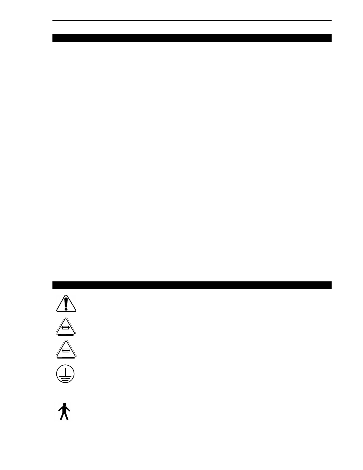
1.6 SYMBOLS
Warning, consult accompanying documents
Fuse rating for bed with the 100V∼ and 120V∼
10A 125V
Fuse rating for beds with 200V∼, 220V∼ and 240V∼
6.3A 250V
Protective earth (ground)
Alternating Current
Type B Equipment
IPX4 Protection from liquid splash
7
Page 8

GOBED+ Operations Manual
WWAARRNNIINNG
G
1.7 SET-UP PROCEDURE
CHECKLIST
It is important to ensure that the bed is working properly before it is put into service. The
following list will help ensure that each part of the bed is checked.
_____ Install the foot and head boards on the bed. Insert the foot board carefully so that the
board and the casing connectors fit in smoothly.
E
NNOOTTE
Boards can be fixed permanently by using two 1/4" flat washers/1/4" spring washers/1/4-20 x 1
3/4" hexagon screws for the head board and two 1/4" flat washers/1/4" spring washers/1/4-20 x
2 1/4" hexagon screws for the foot board. Simply insert a screw and the two different washers in
factory installed nuts (refer to drawing 20-0130L, attached to the parts list L20-001, for the
illustration of the nut (part VE20A1N -ref. no. 17)) accessible through holes located on the inner
sides of the foot end and head end casings.
_____ Plug the power cord to the bed connector at the head end of the bed and into a properly
grounded hospital grade wall outlet. Turn on the power switch loacted on the power
connecter.
The bed is equipped with a hospital grade plug for protection against shock hazard. It must be
plugged directly into a properly grounded receptacle. Grounding reliability can be achieved only
when a hospital grade receptacle is used.
_____ Depress the red “TOTAL BRAKE” side of the pedal at both sides of the bed fully down to
set the brakes (see page 12). Push on the bed to ensure it is immobilized. Toggle the
pedal to the neutral position and ensure the brakes are released.
_____ Depress the green “AXIAL STEER” side of the pedal at both sides of the bed fully down
to put the bed in the steer mode (see page 12). Ensure the 5th steer wheel is properly
engaged. Toggle the pedal to the neutral position and ensure the 5th wheel disengages.
_____ Ensure the siderails raise, lock in the up position and lower smoothly (see page 15).
_____ Run through each control of the foot board control panel (see page 17).
_____ Verify the optional Weigh and Bed Exit systems for proper operation (see page 18,
"Operating (Zeroing) the Scale…" and page 20 or 21, "To activate the Bed Exit…").
_____ Run through each function on both head end siderails (see page 16).
_____ Raise the bed to full up position and activate the Trendelenburg function (see page 17).
Ensure the head end lowers to the full down position.
_____ Raise the bed to the full up position and activate the reverse Trendelenburg function (see
page 17). Ensure the foot end lowers to the full down position.
_____ Verify the optional CPR hold-to-run release mechanism. Raise the Fowler to full up.
Using the CPR release handle (see page 14), lower the Fowler gradually to flat position
by pulling, holding and releasing the handle several times. Ensure the Knee Gatch (if
raised) also start flattening when the Fowler is completely down. Verify that the Fowler
actuator resets itself when the Fowler is completely lowered. Note that during the Fowler
motor reset period, the bed functions are not available.
_____ Verify the following optional equipments for proper operation: 120V auxiliary outlet, night
light, two or three function pendant control, emergency crank operation, etc.
If any problems are found during bed set-up, contact our Technical Service department (see
section 1.2).
8
Page 9

Introduction Chapter 1
CCAAUUTTIIOON
N
WWAARRNNIINNG
1.8 CLEANING AND PREVENTATIVE MAINTENANCE
BED CLEANING AND MATTRESS CARE
WWAARRNNIINNG
G
Always unplug the bed power cord from the wall outlet when cleaning or servicing the bed.
Do not use harsh cleaners, solvents or detergents. Do not steam clean, hose off or
ultrasonically clean the bed. Do not immerse any part of the bed. The bed electrical parts may
be damaged by exposure to water.
Germicidal disinfectant, used as directed, and/or Chlorine Bleach products are not considered
mild detergents. These products are corrosive in nature and may cause damage to your bed if
used improperly. If these types of products are used, ensure the beds are rinsed with clean
water and thoroughly dried following cleaning. Failure to properly rinse and dry the beds will
leave a corrosive residue on the surface of the bed, possibly causing premature corrosion of
critical components. Failure to follow the above directions when using these types of cleaners
may void this product warranty.
Bed Cleaning
Hand wash all surfaces of the bed with a soft cloth moistened with a solution of lukewarm water
and a mild detergent.
Wipe the bed clean and dry thoroughly to avoid build up of cleaning solution.
E
NNOOTTE
Do not use cleaning solutions containing a degreaser near the siderail pivots (see figure 2.2B on
page 11 of the Maintenance Manual) to avoid deteriorating the grease used to ensure a smooth
movement of the siderails.
Mattress Care
G
Inspect the mattress after each use. Discontinue use if any cracks or rips are found in the
mattress cover which may allow fluid to enter the mattress. Failure to properly clean the
mattress, or dispose of it if defective, may increase the risk of exposure to pathogenic
substances and may bring about diseases to the patient and user.
• Inspection
Implement local policies to address regular care, maintenance, and cleaning of mattresses and
covers. The cover cleaning procedure can be found below and on the bed label.
Inspect mattress cover surface (also zip fasteners and cover inner surface if mattresses have
zip fasteners) regularly for signs of damage. If the mattress cover is heavily stained or soiled, or
torn, remove the mattress from service.
• Cleaning
Stains: Wash with lukewarm water using a mild detergent. Rinse with water and let dry. For
tough stains use bleach diluted with ten parts of water.
9
Page 10

GOBED+ Operations Manual
PREVENTATIVE MAINTENANCE
Annual Checklist
____ All fasteners secure.
____ Inspect for excessive wear the oil-impregnated bronze shoulder spacers found at the bed
hinge points. Replace as needed. Do not lubricate these spacers.
____ Engage the “TOTAL BRAKE” pedal at both sides of the bed and ensure the brakes are
applied. Toggle the pedal to neutral and ensure the brakes are released.
____ Engage the “Axial Steer” pedal at both side of the bed and ensure the 5th steer wheel
engages properly. Toggle the pedal to neutral and ensure the 5th wheel disengages.
____ Siderails move, latch and stow properly (see page 15).
____ All functions on the foot board working properly, including LED's (see page 17).
____ Calibrate the optional scale system (see section 4.6 “Scale System Calibration” of the
bed Maintenance manual).
____ All siderail functions working properly (see page 16). Verify the nurse call function, alarm
sounds in the nurse station?
____ Optional CPR hold-to-run release handles working properly (see page 14). Fowler and
Knee Gatch (if raised) flatten. Fowler control motor resets itself automatically as soon as
the fowler is completely lowered.
____ Verify the Fowler, Knee Gatch and Hi-lo movements to ensure that the motion interrupt
switch integrated to each of the four actuators is operating properly.
____ Auxiliary outlet (option available only with 120V electric system beds) working properly
(see page 14).
____ Optional night light working properly.
____ Foot prop rod working properly with the Knee Gatch or Contour positioning activated.
____ No cracks or splits in the boards and siderails.
____ Head end bumpers tightly secured to frame and working properly.
____ No rips or cracks in mattress cover.
____ Power cord not frayed.
____ No cables worn or pinched.
____ All electrical connections tight.
____ All grounds secure to the frame.
____ All casters roll properly. Check caster for cuts, wear, etc.
____ Ground chain intact and in place.
____ Inspect and lubricate, if needed, the bed lubrication points described in section 2.2 of the
GOBED+ maintenance manual.
____ Measure current leakage and grounding continuity of the bed and the optional auxiliary
outlet (check with our Technical Service department for the acceptable values).
E
NNOOTTE
Preventive maintenance may need to be performed more frequently based on the usage level of
the bed.
10
Page 11

Introduction Chapter 1
VASCULAR
POSITION
TRENDELENBURG
POSITION
POSITION
MODULE
F
igure 1.10
LOCATION
NURSE CALL CABLE
OPTIONAL NURSE CALL
OUTLET
1.9 BED POSITION PICTOGRAMS
The following pictograms illustrate the basic positions.
Not illustrated here is the Cardiac Chair position that is obtained by combining the reverse
Trendelenburg and the Contour positions.
1.10 BED ILLUSTRATION
OPTIONAL GEN III
PENDANT CONTROL
CABLE CONNECTOR
FOWLER ELEVATION
KNEE GATCH ELEVATION
BED Hi-Lo MOT ION
OPTIONAL EMERGENCY
CRANK STORAGE
PATIENT'S RIGHT
REVERSE TRENDELENBURG
CONTOUR
POSITION
Figure 1.9
PATIENT'S LEFT
HEAD END
SPEAKERPHONE
POWER CORD
CONNECTOR AND
ON/OFF SWITCH
OPTIONAL 37-PIN
CONNECTOR
CPR RELEASE
HANDLE
FOLEY BAG HOOK
SIDERAIL OUTER
CONTROL PANEL
RELEASE LEVER
SIDERAIL
FIFTH STEER
WHEEL
BRAKE/STEER
PEDAL
RESTRAINT STRAP
LOCATION
MATTRESS RETAINER
SIDERAIL INNER
CONTROL PANEL
EMERGENCY CRANK
FOOT BOARD
CONTROL PANEL
FOOT END
QE71-0299
OPTIONAL
AUXILIARY
OPENINGS
11
Page 12

GOBED+ Operations Manual
WWAARRNNIINNG
G
WWAARRNNIINNG
G
2. OPERATION GUIDE
2.1 SWITCHING ON POWER
The bed is equipped with a main power switch located at the head end of the bed where the
power cord connects to the bed. Turn it on to activate the bed functions. When the bed power
switch is turned off or in the event of a power failure, the settings of the lockout controls and the
optional Weigh and/or Bed Exit calibration data are preserved.
2.2 APPLYING THE BRAKES
The bed is equipped with a central locking system activated by a pedal (see page 11, “Bed
Illustration”) located at the midpoint of the bed on both sides.
Always apply the brakes when a patient is on the bed (except during transport) or when
entering/exiting the bed. Serious injury could result if the bed moves while a patient is getting on
or off the bed. After the brake pedal is engaged, push on the bed to ensure the brakes are
securely locked.
Brake Pedal Operation
To engage the wheel brakes, fully depress the red “TOTAL BRAKE” side of the brake/steer
pedal at either side of the bed.
To disengage the wheel brakes, toggle the pedal to the neutral position.
2.3 MOVING THE BED
The bed is equipped with a fifth steer wheel activated by a pedal (see page 11, “Bed
Illustration”) located at midpoint of the bed on both sides.
The fifth steer wheel helps guiding the bed along a straight line and helps the bed pivot around
corners.
To reduce risk of injury, ensure the sleep surface is horizontal and in the lowest position with the
siderails fully raised and locked when moving the bed with a patient in it.
To avoid injury to the patient and/or user, do not attempt to move the bed laterally with the steer
pedal engaged. The fifth steer wheel cannot swivel.
To avoid damage to the siderail mechanisms, do not move the bed using the raised siderails.
Use the push/pull handles integrated to the boards to move the bed.
Steer Pedal Operation
To engage the steer mode, fully depress the green “AXIAL STEER” side of the brake/steer
pedal at either side of the bed.
To remove the steer mode, toggle the pedal to the neutral position.
12
Page 13

Chapter 2 Operation Guide
WWAARRNNIINNG
G
2.4 FOLEY BAG HOOK USAGE
Foley bag hooks (see page 11, “Bed Illustration”) are found at three locations on both sides
of the bed under the edges of the mattress support head, seat and foot sections.
E
NNOOTTE
The Foley bag hooks move when the Fowler is raised or lowered. Fowler motion must be locked
out when using these hooks to avoid inadvertent movement of the hooks.
2.5 FOOT PROP ROD OPERATION
A foot prop rod, integrated to the foot section, engages automatically as the Knee Gatch is
raised thus maintaining the foot section in a nearly horizontal position. The support arm
enables the positioning of the sleep surface into the vascular position (see page 11, “Bed
Positions”).
Since the prop rod is automatically engaged, it must be disengaged manually whenever a
simple Knee Gatch raise is required. To do so, perform the following steps:
1. Before raising the Knee Gatch, reach under the foot section, lift the prop rod and hold it
while raising the Knee Gatch through the foot board control panel.
2. As the Knee Gatch raises, the rod will come to pass the support brackets. Release it
then and continue to raise the Knee Gatch. The foot section will then simply follow the
move of the Knee Gatch without being propped.
2.6 PATIENT RESTRAINT STRAP LOCATIONS
The bed has 12 locations on the mattress support for installing patient restraint straps. Ten
of them are located on the mattress support edges directly across from each other and the
remaining two are located on the top edge of the head section (see page 11, “Bed
Illustration”).
Improperly adjusted restraint straps can cause serious injury to a patient. It is the responsibility
of the attending medical personnel to determine proper use of restraint straps and restraint strap
locations.
13
Page 14

GOBED+ Operations Manual
WWAARRNNIINNG
G
WWAARRNNIINNG
2.7 EMERGENCY CPR RELEASE (OPTIONAL)
The CPR release is for emergency use only. When activating the CPR release, all people and
equipment must be removed from the area below and around the head, thigh and foot sections
of the bed or serious personal injury or equipment damage could occur.
When quick access to the patient is needed, and the Fowler is raised, squeeze one of the
two release handles located under the upper right and left sides of the head section (see
page 11, “Bed Illustration”). The Fowler and the knee section (if also raised) will
automatically flatten. The Fowler control motor will reset itself automatically as soon as the
Fowler will be completely lowered.
The handle can be released at any time to stop the Fowler from lowering. Note that the
resetting of the control motor does not occur when the Fowler is not lowered completely.
E
NNOOTTE
During the short period of time the Fowler control motor is resetting, the bed functions are
not available.
2.8 NIGHT LIGHT USAGE (OPTIONAL)
The bed may be equipped with an optional photoelectric night light to illuminate the floor
area around the bed. The night light turns on as the room lights dim.
2.9 NURSE CALL USAGE (OPTIONAL)
The bed may be equipped with an optional nurse call function allowing the patient to
communicate through speakerphones with the nurse station by simply pressing a nurse call red
button integrated to both head end siderail inner control panels (see page 16).
The communication between the patient and the nurse station is established the moment a
member of the nursing staff responds to the call signal.
Included with this option are two Ø1/4" phono jacks located on both sides of the head end
casing. The phono jacks enable the use of a nurse call cord which can be placed within reach of
a patient who is not in bed.
E
NNOOTTE
The nurse call system will automatically send a call signal to the nurse station if the
communication between the bed and the nurse station is interrupted following a power failure,
the switching off of the bed or the disconnection of the nurse call communication cable.
2.10 AUXILIARY POWER OUTLET USAGE (OPTION AVAILABLE W/120V~ BED MODEL)
G
Use only hospital grade electric equipments with the auxiliary power outlet. The use of
normal electric equipments may bring the current leakage to a level unacceptable for
hospital equipment.
The North American version (120V~ electrical system) of the may be equipped with
an optional 120V~ auxiliary power outlet integrating a 5A breaker. Located on the left side at the
foot end of the bed (see page 11, “Bed Illustration”), this feature provides nursing staff with a
convenient power source for peripheral equipments.
E
NNOOTTE
Use only equipment with a current consumption of 5 amp or less.
14
Page 15

Chapter 2 Operation Guide
WWAARRNNIINNG
G
2.11 POSITIONING SIDERAILS
The siderails have one lock position, in the upper position. They can be tucked away against the
mattress support when not in use.
E
NNOOTTE
The rail has to be removed from its tucked position by pulling it outward prior to raise it.
Leave the siderails fully up and locked when the patient is unattended. When raising the
siderails, be sure that you hear the click that signals the up and locked condition. Pull firmly on
the siderail to ensure it is locked into position.
Siderails, with or without their padded covers or nets, are not intended to serve as restraint
devices to keep patient from exiting the bed. Siderails are designed to keep a patient from
inadvertently rolling off the bed. It is the responsibility of the attending medical personnel to
determine the degree of restraint necessary to ensure a patient will remain safely in bed. Failure
to utilize the siderails properly could result in serious patient injury.
Keep siderails in the fully raised position and the sleep surface horizontal in its lowest position
when the patient is sleeping unless the patient's medical conditions dictates otherwise.
To raise a head end siderail, grasp the rail, pull it outward and swing it upward towards the
head end of the bed until it latches in the up position.
To raise a foot end siderail, the same procedure is required as for the head end siderail,
however, the siderail swings to the foot end of the bed.
To lower a siderail, lift it up slightly, push in the release lever located under the mattress
support (see page 11, “Bed Illustration”) and hold siderail as it rotates down to low position.
Push the siderail against the mattress support to tuck it away.
2.12 HEAD AND FOOT BOARD OPERATION
The head and foot boards slide down into two mounting sockets located at each end of the bed.
Both boards can be removed or replaced easily. They may also be mounted permanently (see
page 8, “Set-Up Procedures”).
Removing Boards
Seize both ends of the board and lift it up until posts come out of the mounting sockets.
Replacing Boards
• Head board: Insert the board with the laminated finish side facing inside the bed.
• Foot board: Insert the board with the laminated finish side facing outside the bed. Be
cautious when inserting the foot board to avoid damaging the board and foot end casing
connectors.
E
NNOOTTE
If the foot board must be removed and the bed electric functions remain accessible through the
siderails, ensure that the siderail functions are operational by deactivating all three lockout
switches in the foot board control panel (see page 17) before removing the foot board.
15
Page 16

GOBED+ Operations Manual
Figure 2.13A
B
D
F A
C E E C
A F
D B
E D
B C
A A
C
D
E F F
2.13 HEAD SIDERAIL FUNCTION GUIDE
Outside Siderail (Patient's Right Rail) Outside Siderail (Patient's Left Rail)
A: Press to raise Fowler D: Press to lower sleep surface
B: Press to lower Fowler E: Press to raise Knee Gatch
C: Press to raise sleep surface F: Press to lower Knee Gatch
Inside Siderail (Patient's Right Rail) Inside Siderail (Patient's Left Rail)
Figure 2.13B
A: Press to raise Fowler C: Press to raise Knee Gatch
B: Press to lower Fowler D: Press to lower Knee Gatch
E: Press to activate the Nurse Call function (optional)
Figure 2.13C
F: Nurse call speakerphones (this panel is optional equipment and will be present on
the inner side of both head siderails if the bed is equipped with the Nurse Call option,
see page 14, “Nurse Call Usage”).
16
Page 17

Chapter 2 Operation Guide
B2 C1 C2 D1 D2 E1 E2 F A3 A2 A1
2.14 FOOT BOARD CONTROL PANEL GUIDE
B1
Figure 2.14
A1: Press to lock out Fowler controls at both head siderails. The Fowler padlock icon will come
on. Press again to unlock.
A2: Press to lock out Knee Gatch controls at both head siderails. The Knee Gatch padlock icon
will come on. Press again to unlock.
A3: Press to lock out the bed height adjustment (Hi-lo) at both head siderails (outer sides). The
Hi-lo padlock icon will come on. Press again to unlock.
E
NNOOTTE
The foot board controls are not affected by the lockout switches.
Lockout settings are automatically saved in the event of a power failure and restored following
resumption of power.
B1: Press to raise Fowler
B2: Press to lower Fowler
C1: Press to raise Knee Gatch
C2: Press to lower Knee Gatch
D1: Press to raise the sleep surface
D2: Press to lower the sleep surface
E1: Press to obtain the Trendelenburg position (head down, foot up)
E2: Press to obtain the reverse Trendelenburg position (head up, foot down)
E
NNOOTTE
To replace the sleep surface to horizontal position after a Trendelenburg positioning, simply use
the bed height controls to either raise or lower the sleep surface to its limits. Then position the
bed to the desired height.
F: Contour positioning control. The Contour positioning function is operational by default
(padlock icon off). To deactivate it, press on the Contour switch (F) (padlock icon lights up). The
Contour and Knee Gatch lockout controls are interrelated, activating one activates the other.
2.15 FUNCTION LOCKOUT USAGE
Whenever a patient or visitor should be restricted from operating the siderail controls, activate
the appropriate lockout switch (A1, A2, A3, figure 2.16) in the foot board control panel. The
lockout switches are for the safety of the patient. Use them when appropriate.
E
NNOOTTE
The padlock icon related to the function that is locked will light up.
17
Page 18

GOBED+ Operations Manual
/
ENTER
WWAARRNNIINNG
G
D B C A
2.16 WEIGH SYSTEM CONTROL PANEL GUIDE (OPTIONAL)
E
NNOOTTE
When the bed is switched on, the scale display will show "STRYKER / SCALE V x.x" where x.x is the
version of the control software.
The Weigh system is intended to assist in the monitoring of the patient's weight variation. Under no
circumstances should its reading be used as sole reference for medical treatment.
A: key:
• Press the key once to activate
the display. The Scale mode will
be displayed.
• Press when instructed to press
ENTER.
B/C: MENU Up/Down keys:
• Press either key repeatedly until
Figure 2.16
desired mode is reached.
D: Scale Display.
Scale Menu Modes
Order of appearance of the modes when the MENU Down key is pressed repeatedly:
Mode Display First Line
Scale WEIGHT ANGLE
Change Equipment CHANGE EQUIP.
Change Patient Weight CHNG PTNT WEIGHT
Select Weight Unit (lb/kg) UNITS
Scale Zero SCALE ZERO
Operating (Zeroing) the Scale Before Putting a New Patient on the Bed
• Prepare the bed for a patient stay (linens, pillows, etc.) and press the key, the display will
read:
WEIGHT ANGLE
XXX.X lb +/- XX.X°
• Press the MENU Up key to access the Scale Zero mode (as written on the membrane). The
display will read:
SCALE ZERO / PRESS ENTER
• Press and hold the ENTER key. The display will read:
HOLD TO ZERO WT. (keep pressing the ENTER key), followed by:
RELEASE TO ZERO (release the ENTER key), followed by:
DO NOT TOUCH BED (be sure nobody touches the bed while this message appears).
• The scale system will return to the Scale mode and will display zero for the weight and angle
values. The bed is now ready for the patient.
E
NNOOTTE
The scale display turns off automatically after one minute of idle time, but the system itself will
remains active in the background. Pressing the key will reactivate the display in the Scale mode.
On beds equipped with the Weigh and Bed Exit systems, zeroing one system will also zero the
other.
Do not zero the bed while a patient is on the bed. An inaccurate patient weight reading will result. If
this should occur, use the Change Patient Weight mode to enter the correct patient weight or
remove the patient from the bed and zero the bed again (see above “Operating (Zeroing) the Scale
Before Putting a New Patient on the Bed”).
18
Page 19

Chapter 2 Operation Guide
PRESS ENTER
PRESS ENTER
Adding or Removing Equipment when a Patient is on the Bed
E
NNOOTTE
Take note of the patient's weight before proceeding with the Change Equipment mode.
The patient's weight should remain the same at the end of the procedure. If it is not the case, access
the Change Patient Weight mode using the MENU Up or Down keys and enter manually the
previously noted patient weight.
• Press the key to activate the scale display.
• Access the Change Equipment mode using the MENU Down key, the display will read:
CHANGE EQUIP / PRESS ENTER
• Press and hold the ENTER key. The display will read:
RELEASE TO START (release the ENTER key), followed by:
DO NOT TOUCH BED (be sure no one touches the bed while this message appears).
• The ADD/REMOVE EQUIP / PRESS ENTER message will then appear, signalling that
equipment can now be added or removed from the bed.
When done, press and hold the ENTER key.
• Display will read RELEASE TO FIN. (release the ENTER key), followed by:
• DO NOT TOUCH BED (ensure the patient stands still as much as possible and no one
touches the bed while this message is displayed).
• The scale will return to the Scale mode displaying the patient unchanged weight.
Changing Manually the Numerical Value of Displayed Weight
In certain circumstances, it may be necessary to change manually the displayed patient's weight. To
do so:
• Press the key to activate the scale display.
• Access the Change Patient Weight mode using the MENU Down key. The display will read:
CHNG PTNT WEIGHT / PRESS ENTER
• Press and hold the ENTER key. The display will read:
REL. TO CHNG WT. (release the ENTER key), followed by:
DO NOT TOUCH BED (be sure no one touches the bed while this message appears).
• The display will then read pq XXX.X lb / press ENTER. Adjust the weight using the MENU
Up/Down keys.
• Once done press the ENTER key.
• The scale will return to the Scale mode and will display the adjusted weight.
The Change Patient Weight mode should not be used systematically for new patients. The scale
should be zeroed each time a new patient enters onto the bed (see page 18, "Operating (Zeroing)
the..).
Changing the Weight Measure Unit
• Press the key to activate the scale display. Access the Select Weight Unit (lb/kg) mode
using the MENU Down key. The display will read:
UNITS / PRESS ENTER
• Press the ENTER key. The display will read:
• Select the weight unit using the MENU Up or Down key and press the ENTER key. The scale
will return to the Scale mode with the weight in the unit chosen.
pq lb AND
OR
pq kg AND
19
Page 20

GOBED+ Operations Manual
A B
2.17 CHAPERONE BED EXIT (OPTIONAL)
A: Press to activate/deactivate the Bed Exit
function
B: Armed LED
NNOOTTE
Figure 2.17
E
For the bed exit alarm signal to be heard in the nurse station, the bed must be equipped with the
optional nurse call function and be connected to the hospital nurse call system. For beds
equipped with the Bed Exit function but not with the Nurse Call option, the alarm signal will be
heard only in the patient's room.
Be sure to place the patient on the bed in its normal position before activating the bed exit.
WWAARRNNIINNGG
The Bed Exit system is intended only to aid in the detection of a patient exiting the bed. It is not
intended to replace patient monitoring protocol. The Bed Exit system signals when a patient is
about to exit the bed. Adding or removing objects from the bed after having armed the Bed Exit
system may cause a reduction in the sensitivity of the Bed Exit system, resulting in erroneous
readings of the patient's movements in the bed.
The Bed Exit system is not designed to be used with patients weighing less than 50 lb (23 kg).
E
NNOOTTE
When the bed is equipped with a scale, the scale must be properly zeroed for the Bed Exit to
function properly (see page 18, “Operating (Zeroing) the Scale Before Putting a New Patient on
the Bed”). If the bed is not equipped with a scale, follow the procedure below:
• Before putting a new patient on the bed: prepare the bed for a patient stay by adding linens
and equipment to the bed.
• Press and hold the ARM/DISARM key (A) until the ARMED LED (B) begins to flash (do not
touch the bed while the LED flashes), then release the key. When the ARMED LED turns
off, the system is zeroed.
To activate the Bed Exit, press the ARM/DISARM key (A). The ARMED LED (B) will come on.
To deactivate the Bed Exit after an alarm or simply to turn it off, press the ARM/DISARM key
(A). The Armed LED (B) will turn off.
20
Page 21

Chapter 2 Operation Guide
A C B D
2.18 CHAPERONE BED EXIT WITH ZONE CONTROL (OPTIONAL)
A: Press to activate/deactivate the Bed Exit
function
B: Zone LED's
C: Press to select zone
D: Zone icons (zone from left to right: less
restrictive to most restrictive, see below)
NNOOTTE
Figure 2.18
E
For the bed exit alarm signal to be heard in the nurse station, the bed must be equipped with the
optional nurse call function and be connected to the hospital nurse call system. For beds equipped
with the Bed Exit function but not with the Nurse Call option, the alarm signal will be heard only in
the patient's room.
Be sure to place the patient on the bed in its normal position before activating the bed exit.
WWAARRNNIINNG
G
The Bed Exit system is intended only to aid in the detection of a patient exiting the bed. It is not
intended to replace patient monitoring protocol. The Bed Exit system signals when a patient is about
to exit the bed. Adding or removing objects from the bed after having armed the Bed Exit system
may cause a reduction in the sensitivity of the Bed Exit system, resulting in erroneous readings of
the patient's movements in the bed. Failure to set the Chaperone zone properly could result in
improper monitoring and patient injury. Verify that the proper zone is selected before leaving the
patient.
The Bed Exit system is not designed to be used with patients weighing less than 50 lb (23 kg).
Zone Settings
• The first zone (left LED) is the traditional Bed Exit zone. The patient can move in the bed freely
but cannot fully exit the bed or the alarm will sound.
• The second zone (middle LED) is more restrictive. It allows the patient to sit up and roll over but
any attempt to exit the bed will cause the alarm to sound.
• The third zone (right LED) is the most restrictive zone. Small movements like raising an arm or
lifting the shoulder off the bed will cause the alarm to sound. The third zone is used to alert staff
to a change in the condition of an unconscious or paralyzed patient.
E
NNOOTTE
When the bed is equipped with a scale, the scale must be properly zeroed for the Bed Exit to
function properly (see page 18, “Operating (Zeroing) the Scale Before Putting a New Patient on the
Bed”). If the bed is not equipped with a scale system, follow the procedure below:
• Before putting a new patient on the bed: prepare the bed for a patient stay by adding linens and
equipment to the bed.
• Press and hold the ARM/DISARM key (A) until the larger zone LED (B) begins to flash (do not
touch the bed while the LED flashes), then release the key. When the zone LED turns off, the
system is zeroed.
To activate the Bed Exit, press the ARM/DISARM key (A). The less restrictive zone (B) will be
automatically selected and its LED will come on. To change the zone, press the ZONE key (C)
repeatedly until the desired zone LED comes on.
To deactivate the Bed Exit after an alarm or simply to turn it off, press the ARM/DISARM key (A).
The zone LED (B) will turn off.
21
Page 22

GOBED+ Operations Manual
3. ACCESSORIES
Listed below are all the accessories that may be attached to the as well as their
maximum load capacity where applicable.
• Two function pendant control with hook (Product & Design)
• Three function pendant control with hook (Product & Design)
• Three function pendant control (Neeco-Tron Inc)
• Upright oxygen bottle holder (Maximum load: 75 lb - 34 kg)
• Defibrillator tray (Maximum load: 40 lb - 18 kg)
• Sheet cradle
• Overhead trapeze system (Maximum load: 150 lb -68 kg)
• 1" Ø removable anodized aluminium IV pole
• 1" Ø fixed anodized aluminium IV pole
• 1/2" Ø removable anodized aluminium IV pole
• Emergency crank
• Padded siderail covers (set of two - head only)
• Padded siderail covers (set of four)
22
 Loading...