

Page 1
Altrix™ Precision Temperature Management System
8001
Operations Manual
2016/12 G.1 8001-009-001 REV G
www.stryker.com
Page 2

sample text
Page 3
Symbols
~
ONLY
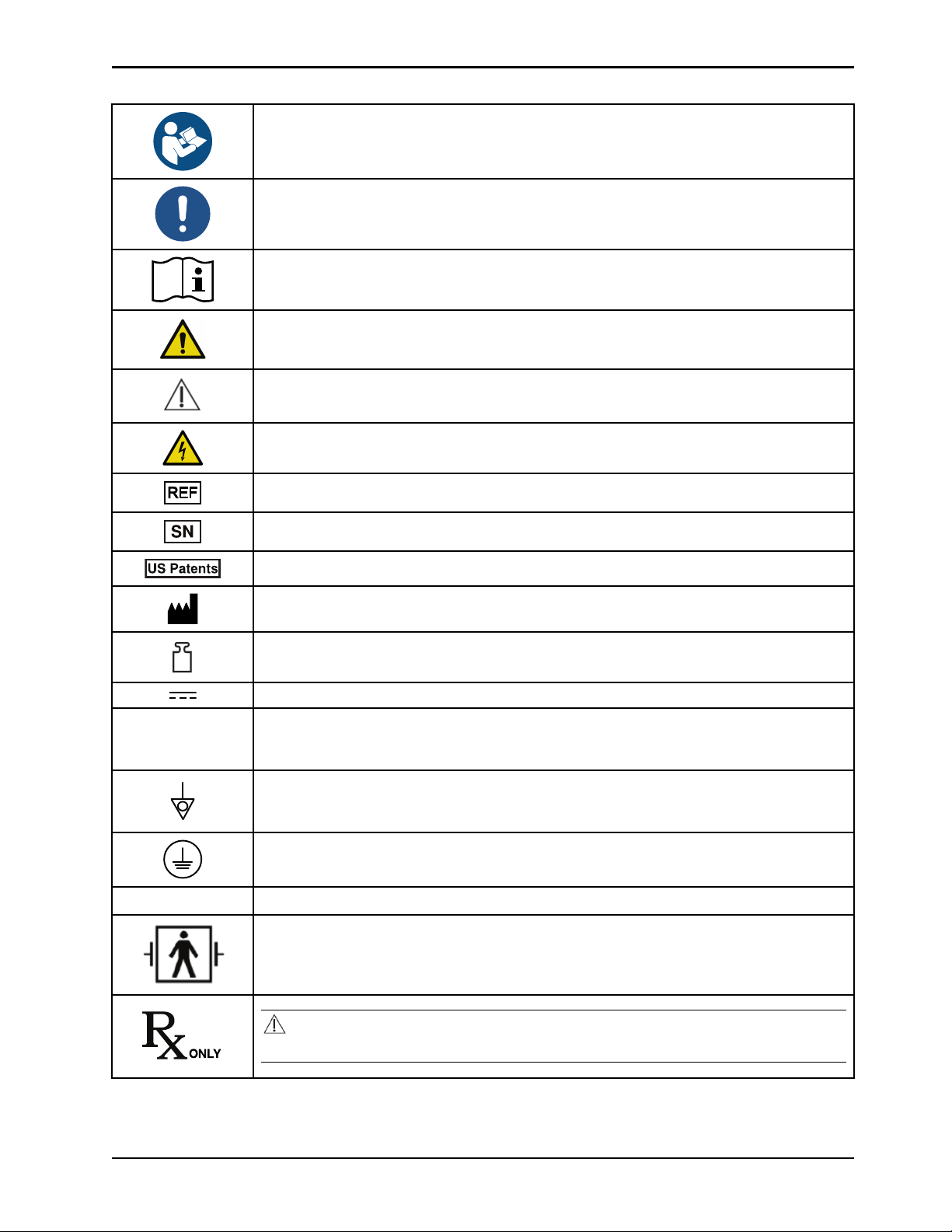
Refer to instruction manual/booklet
General mandatory action sign
Consult instructions for use
General warning
Caution
Warning; electricity
Catalogue number / model
IPX1
Serial number
For US Patents see www.stryker.com/patents
Manufacturer
Mass of equipment
Direct current
Alternating current
Product provides terminal for connection of a potential equalization conductor. The potential
equalization conductor provides direct connection between the product and potential
equalization busbar of the electrical installation.
Protective earth ground
Protection from dripping water from above the device
Defibrillation proof type BF applied part
CAUTION
Federal law (USA) restricts this device to sale by or on the order of a physician.
www.stryker.com 8001-009-0 01 REV G
Page 4
87VL Medical
Electrical Equipment
Symbols
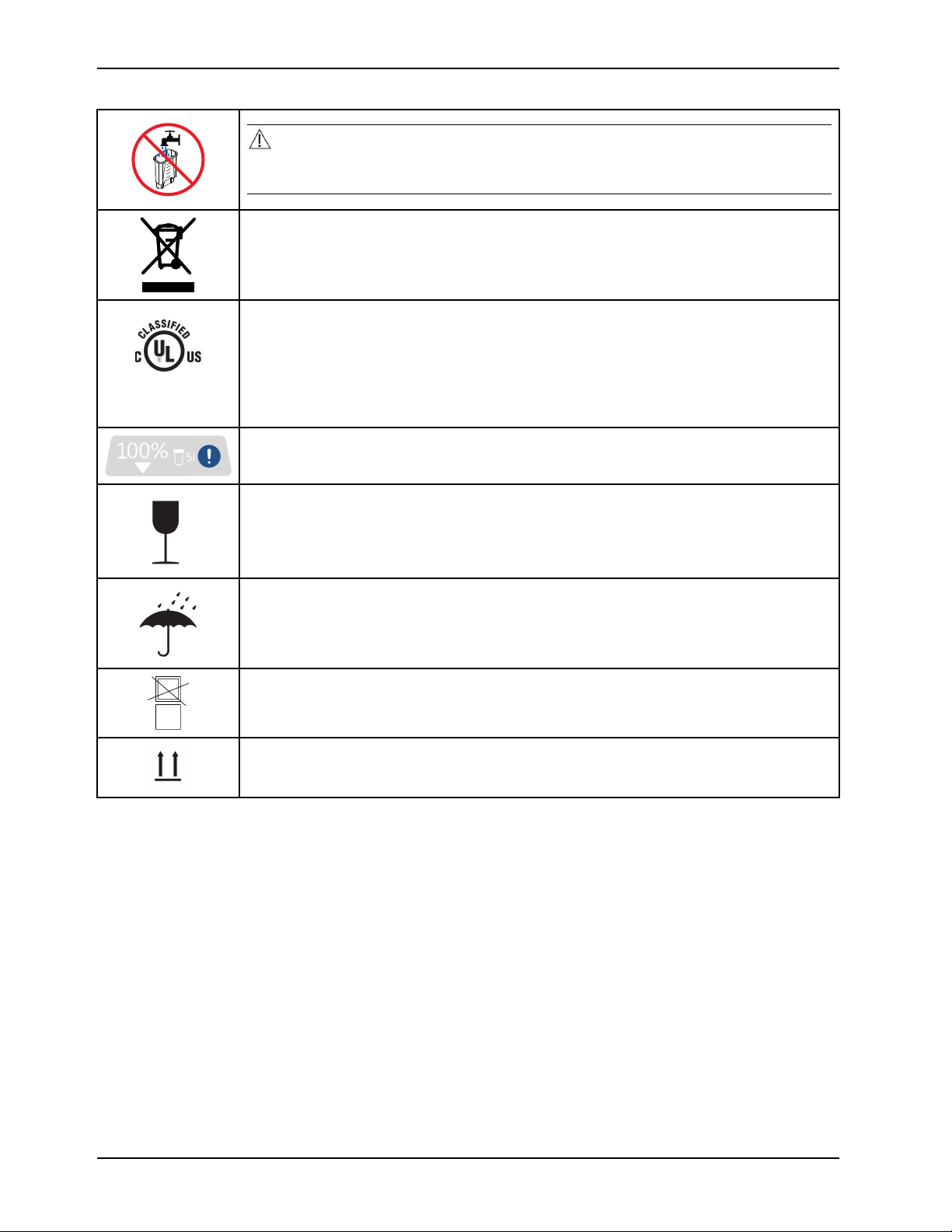
CAUTION
Always use sterile distilled water or water that has been passed through a filter less than or
equal to 0.22 microns with this product.
In accordance with European Directive 2012/19/EU on Waste Electrical and Electronic
Equipment, this symbol indicates that the product must not be disposed of as unsorted
municipal waste, but should be collected separately. Contact your local distributor for disposal
information.
Medical Equipment Classified by Underwriters Laboratories Inc. with Respect to Electric Shock,
Fire, Mechanical and Other Specified Hazards Only in Accordance with IEC 60601-1:20 05 (3rd
edition), ANSI/AAMI ES60601-1 (2005, 3rd edition), CAN/CSA C22.2 No. 60601-1:20 08, IEC
80601-2-35:2009, CAN/CSA C22.2 NO 80601-2-35:12, ISO 80601-2-56:2009, CAN/CSA C22.2
NO 80601-2-56:12, IEC 60601-1-8:2007, CAN/CSA C22.2 NO 60601-1-8-08, IEC 60601-110:2008, CAN/CSA C22.2 NO 60601-1-1 0-09, IEC 60601-1-6, CAN/CSA-C22.2 No. 60601-16:11
Liquid level indicator
Fragile, handle with care
Keep dry
Do not stack
This way up
8001-009-0 01 REV G www.stryker.com
Page 5

Table of Contents
Warning/Caution/Note Definition...................................................................................................................4
Summary of safety precautions ....................................................................................................................5
Introduction..............................................................................................................................................7
Product description..............................................................................................................................7
Indications for use ...............................................................................................................................7
Intended users.................................................................................................................................... 8
Expected service life ............................................................................................................................ 8
Contraindications................................................................................................................................. 8
Specifications..................................................................................................................................... 8
Product illustration ............................................................................................................................. 10
Product system ................................................................................................................................. 11
Product functions .............................................................................................................................. 12
Buttons ..................................................................................................................................... 12
Visual indicators.......................................................................................................................... 13
Graphical user interface icons........................................................................................................ 14
Product alarms ................................................................................................................................. 15
Alarm priority and description ......................................................................................................... 15
Contact information............................................................................................................................ 18
Serial number location........................................................................................................................ 18
Date of manufacture .......................................................................................................................... 18
Setup.................................................................................................................................................... 19
Inspecting........................................................................................................................................ 19
Selecting a language.......................................................................................................................... 19
Testing visual and audible alarms ......................................................................................................... 19
Operation .............................................................................................................................................. 21
Placing the product............................................................................................................................ 21
Applying or releasing the wheel locks..................................................................................................... 21
Selecting and connecting a temperature probe ........................................................................................ 22
Connecting the reusable patient temperature output cable ......................................................................... 22
Connecting the insulated hoses............................................................................................................ 23
Disconnecting the insulated hoses ........................................................................................................ 24
Connecting and disconnecting thermal transfer devices............................................................................. 24
Powering on the product ..................................................................................................................... 25
Removing and replacing the reservoir .................................................................................................... 26
Filling the reservoir with sterile distilled water........................................................................................... 26
Selecting and setting the primary probe.................................................................................................. 27
Filling a thermal transfer device............................................................................................................ 28
Selecting a therapy mode.................................................................................................................... 28
Starting Automatic therapy mode .......................................................................................................... 29
Setting or editing the cooling rates......................................................................................................... 29
Setting or editing the warming rates.......................................................................................................30
Starting Manual mode ........................................................................................................................ 30
Starting Monitor mode ........................................................................................................................ 31
www.stryker.com 8001-009-0 01 REV G 1
Page 6

Table of Contents
Switching modes............................................................................................................................... 31
Pausing and resuming therapy .............................................................................................................31
Displaying the data storage.................................................................................................................. 31
Opening and securing items in the storage compartment ........................................................................... 32
Stopping therapy or powering off the product........................................................................................... 33
Draining the thermal transfer devices..................................................................................................... 33
Draining water from the reservoir .......................................................................................................... 33
Draining water from the controller and hoses........................................................................................... 34
Storing the power cord and hoses......................................................................................................... 35
Storing the controller .......................................................................................................................... 35
Transporting the product..................................................................................................................... 36
Cleaning................................................................................................................................................ 37
Cleaning the external surfaces............................................................................................................. 37
Disinfecting ............................................................................................................................................ 38
Disinfecting external surfaces .............................................................................................................. 38
Disinfect the internal water circuit and hoses every 14 days........................................................................ 39
Draining the internal water circuit and hoses for disinfection ....................................................................... 39
Disinfecting the internal water circuit and hoses ....................................................................................... 41
Rinsing the internal water circuit and hoses............................................................................................. 43
Accessories ........................................................................................................................................... 45
Thermal transfer devices .................................................................................................................... 45
Thermal transfer device kits................................................................................................................. 45
Patient temperature probes ................................................................................................................. 46
Cables ............................................................................................................................................ 46
Hoses ............................................................................................................................................. 46
Troubleshooting ...................................................................................................................................... 47
Preventive maintenance............................................................................................................................ 49
Cleaning tools......................................................................................................................................... 50
Alarm conditions...................................................................................................................................... 51
Check patient probe alarm .................................................................................................................. 51
Patient probe malfunction alarm ........................................................................................................... 52
Patient probe disconnect alarm ............................................................................................................ 52
Patient temperature deviation medium alarm ........................................................................................... 52
Patient temperature output deviation alarm ............................................................................................. 52
Normothermia deviation alarm.............................................................................................................. 52
Water temperature deviation alarm group ............................................................................................... 52
Check water flow alarm ...................................................................................................................... 53
Power backup level alarm ................................................................................................................... 53
Therapy paused time out alarm ............................................................................................................ 53
Remove from use mode...................................................................................................................... 54
EMC Information ..................................................................................................................................... 55
Warranty ............................................................................................................................................... 59
Warranty exclusion and damage limitations............................................................................................. 59
2 8001-009-001 REV G www.stryker.com
Page 7

Table of Contents
To obtain parts and service.................................................................................................................. 59
Return authorization........................................................................................................................... 59
Damaged product.............................................................................................................................. 59
International warranty clause ............................................................................................................... 59
www.stryker.com 8001-009-0 01 REV G 3
Page 8

Warning/Caution/Note Definition
The words WARNING, CAUTION , and NOTE carry special meanings and should be carefully reviewed.
WARNING
Alerts the reader about a situation which, if not avoided, could result in death or serious injury. It may also describe
potential serious adverse reactions and safety hazards.
CAUTION
Alerts the reader of a potentially hazardous situation which, if not avoided, may result in minor or moderate injury to the
user or patient or damage to the product or other property. This includes special care necessary for the safe and
effective use of the device and the care necessary to avoid damage to a device that may occur as a result of use or
misuse.
Note: Provides special information to make maintenance easier or important instructions clearer.
4 8001-009-001 REV G www.stryker.com
Page 9

Summary of safety precautions
Always read and strictly follow the warnings and cautions listed on this page. Service only by qualified personnel.
WARNING
• Always turn or re-position the patient over the duration of therapy, if possible, to reduce the risk of pressure ulcers.
Follow your hospital protocol.
• Always check the integrity of the patients skin and temperature according to hospital protocol when using the Altrix
system.
CAUTION
• Improper usage of the product can cause injury to the patient or operator. Operate the product only as described in
this manual.
• Do not modify the product or any components of the product. Modifying the product can cause unpredictable
operation resulting in injury to patient or operator. Modifying the product also voids its warranty.
• Shock Hazard - Improper handling of the power cord may damage the power cord and cause potential shock
hazards. If damage has occurred to the power cord, immediately remove the temperature management system from
service to avoid the risk of serious injury or death. Contact the appropriate maintenance personnel.
• Take special precautions regarding electromagnetic compatibility (EMC) when using medical electrical equipment
like Altrix. Install and place Altrix into service according to the EMC information located in the EMC section of this
manual. Portable and mobile RF communications equipment can affect the function of Altrix.
• Shock Hazard. If the internal electrical components are exposed, because the side panel or cover are compromised,
remove the product from use.
• Always make sure that the product reaches room temperature before you setup or operate the product.
• Before first use, disinfect the internal water circuit.
• Do not use Altrix located near or stacked with other medical equipment. If it is necessary to locate Altrix near other
medical equipment, make sure it operates as intended.
• Always apply the wheel locks to prevent unintended movement.
• Always use Stryker accessories. Only IEC 60601-1 equipment shall be hooked to the patient temperature ports.
Failure to comply with these instructions may invalidate any or all warranties and may negatively affect the products
EMC performance. This also protects the product from cardiac defibrillation.
• Avoid the use of materials of good thermal conductivity, such as water, gel, or similar substances, with the Altrix
system not powered on. This can decrease the temperature of the body of a patient.
• Do not apply thermal transfer devices to patients with ischemic limbs. This may result in harm to the patient.
• Do not use this product if the patient has a transdermal medication (patch) as this can result in increased drug
delivery.
• Always pre-fill the thermal transfer device with sterile distilled water before you apply it to the patient. This is to
reduce the risk of pressure ulcers.
• Electric shock. This equipment must only be connected to a supply mains with protective earth.
• Always plug this product directly into a properly grounded hospital-grade or medical-grade wall outlet to achieve
grounding reliability.
• Do not use high frequency surgical instruments or endocardial catheters while the Altrix system is in use. This is to
avoid the risk of electrical shock, burns, or electromagnetic interference.
• Explosion risk. This product is not suitable for use in the presence of flammable anesthetic mixture with air or with
oxygen or nitrous oxide other than nasal or mask type.
• Do not place cables, hoses, or power cord in walkways to avoid the risk of trip hazards.
• Avoid reduction in water flow. Do not connect two or more thermal transfer devices in a series on a single port.
www.stryker.com 8001-009-0 01 REV G 5
Page 10

Summary of safety precautions
CAUTION (CONTINUED)
• Do not use three or more adult Mul-T-Blanket’s at the same time to avoid the risk of water overflow when you power
off the controller.
• When you operate the product near ambient temperature limitations of 15.0° C (59.0° F) or 32.0° C (89.6° F), you
may experience a reduction in product performance.
• Do not place your fingers in between the reservoir and the sides of the controller, to avoid the risk of pinching your
fingers.
• Always use sterile distilled water or water that has been passed through a filter less than or equal to 0.22 microns
with this product.
• Always fill the reservoir with room temperature sterile distilled water to reduce the risk of burn.
• Do not overfill the reservoir to avoid the risk of water spillage and fall.
• Always make sure that there are no water leaks before starting a defibrillation.
• When using the temperature controlled Automatic therapy mode for warming (min, med, or custom), switching to
other modes, changing the target patient temperature, or changing the therapy selection may impact the overall
benefit of therapy.
• Always monitor the patient for shivering, temperature, signs of intolerance, and skin condition when using this
product.
• Always store the power cord, cables, and hoses before you transport the product to reduce the risk of trip hazard.
• Do not store the product with water in the device.
• Always store the product within the specified environmental condition values.
• Always use extra care when you transport the product long distances and on inclines greater than five degrees. Ask
for help, if necessary, to avoid the risk of tipping.
• Always use the handle to move the product. Do not attempt to move the product by pulling on cables, hoses, or by
any other means.
• Avoid ramps that are steeper than ten degrees to avoid tipping the product.
• Do not hang items on the controller handle to avoid the risk of tipping the product.
• Do not power wash this product.
• Do not use quaternaries that contain glycol ethers as they may damage the reusable accessories.
• Do not disinfect the internal water system with a thermal transfer device attached as this may cause a leak.
• Do not use bleach or any other cleaning or disinfectant agents for internal circuits. This could result in damage to the
product. Only use approved disinfectant tablets.
• Always drain the product before disinfecting the internal water circuit. Failure to drain the product may reduce the
effectiveness of the disinfection process.
• Always remove the product from use before servicing any components. Contact qualified service personnel for
service.
Notes
• Disinfection of the Altrix internal water system was validated using M. mucogenicum.
6 8001-009-001 REV G www.stryker.com
Page 11

Introduction
This manual assists you with the operation or maintenance of your Stryker product. Read this manual before operating or
maintaining this product. Set methods and procedures to educate and train your staff on the safe operation or
maintenance of this product.
CAUTION
• Improper usage of the product can cause injury to the patient or operator. Operate the product only as described in
this manual.
• Do not modify the product or any components of the product. Modifying the product can cause unpredictable
operation resulting in injury to patient or operator. Modifying the product also voids its warranty.
Notes
• This manual is a permanent part of the product and should remain with the product even if the product is sold.
• Stryker continually seeks advancements in product design and quality. This manual contains the most current
product information available at the time of printing. There may be minor discrepancies between your product and
this manual. If you have any questions, contact Stryker Customer Service or Technical Support at 1-800-327-0770.
Product description
The Stryker model 8001Altrix™ Precision Temperature Management System can supply water to an individual or multiple
thermal transfer devices simultaneously with each of these circuits monitored separately. Three operating modes are
available to ease patient care: Automatic, Manual, and Monitor. The controller uses the patient temperature probe to
provide closed loop feedback for automatic patient temperature management and monitoring. The controller alarms
visual and audible indications for when safety parameters are exceeded or it detects system function or performance
irregularities. The Altrix system is able to provide a patient temperature output reference signal to be connected to a nonspecific third party device or system.
The controller regulates water temperatures between 4.0° C (39.2° F) and 40.0° C (104.0° F) and circulates the heated or
cooled water via hose sets through the thermal transfer devices. A graphical display provides the user an interface for
selecting desired water or patient temperature settings, operating modes, help menus, and other key parameters. Visual
indicators are displayed to inform the user of system status or when the user must confirm a setting selection. The
system’s water temperature and flow outputs can be monitored with 400 series compatible devices to optimize system
operation.
The Altrix system includes the following components:
• controller
• reusable hose sets
• thermal transfer devices (blankets, vests, and leg wraps)
• patient temperature probes
• reusable adapter cables
• reusable patient temperature output cable
Note: The blankets, vests, leg wraps, and patient temperature probes are type BF applied parts.
Indications for use
The Altrix system is intended for circulating temperature controlled warm or cold water via patient contact thermal
transfer devices for the application of regulating human body temperature in situations where a physician or clinician with
prescription privileges determines that temperature therapy is necessary or desirable.
Indications for use for the Altrix system include:
• Maintain pre-set body temperature as determined by the physician
• Maintain normal body temperature during surgical procedures
www.stryker.com 8001-009-0 01 REV G 7
Page 12
Introduction
Indications for use (Continued)
• For use in all clinical settings including coronary care units, operating, recovery and emergency departments, burn
units, and medical/surgical units
• Adult and pediatric patients
• Monitoring and controlling patient temperature
• Temperature reduction in patients where clinically indicated, e.g. in hyperthermic patients
Intended users
• Physicians
• Advanced Practice Registered Nurses
• Nurses
Expected service life
The Altrix controller has a five year expected service life under normal use, conditions, and with appropriate periodic
maintenance. See the maintenance manual for preventive maintenance and service information.
Contraindications
For core body temperature regulation:
• Raynaud’s Phenomenon (primary or secondary)
• Application to lower extremities distal to aortic cross-clamping
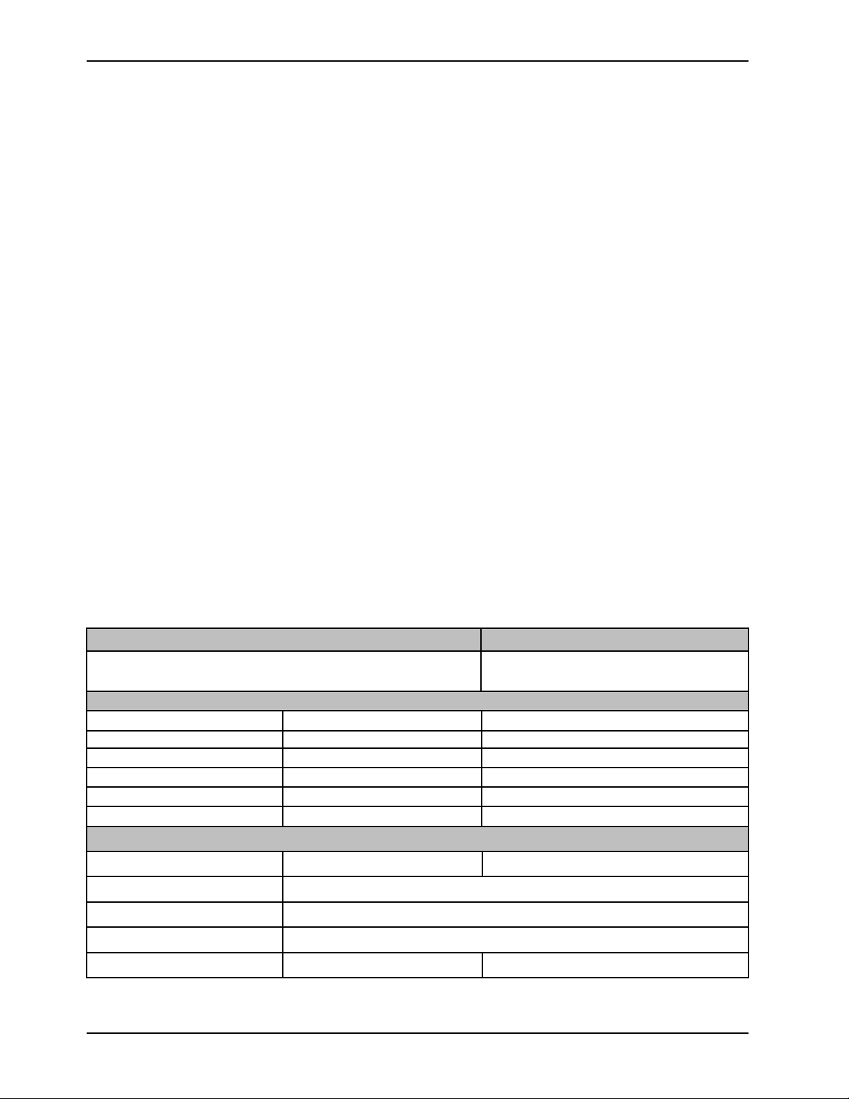
Specifications
Model 8001-000-001
Electrical Requirements - AC Voltage Input Current and Voltage
Ratings
Physical dimensions
Height 42.5 in. 107.9 cm
Width 15.0 in. 38.1 cm
Depth 23.0 in. 58.4 cm
Empty weight 150.0 lb 68.0 kg
Filled weight 160.5 lb 72.8 kg
Reservoir capacity 1.3 gal 5.0 L
Water temperature
Control setting range
39.2° - 104.0° F
120VAC, 60Hz 12A
4.0° - 40.0° C
Control accuracy ±0.3° C (4.0° - 40.0° C)
Display measurement accuracy
Display / resolution setting
Default setting 104.0° F 40.0° C
8 8001-009-001 REV G www.stryker.com
±0.2° C (4.0° - 40.0° C)
0.1° C
Page 13
Specifications (Continued)
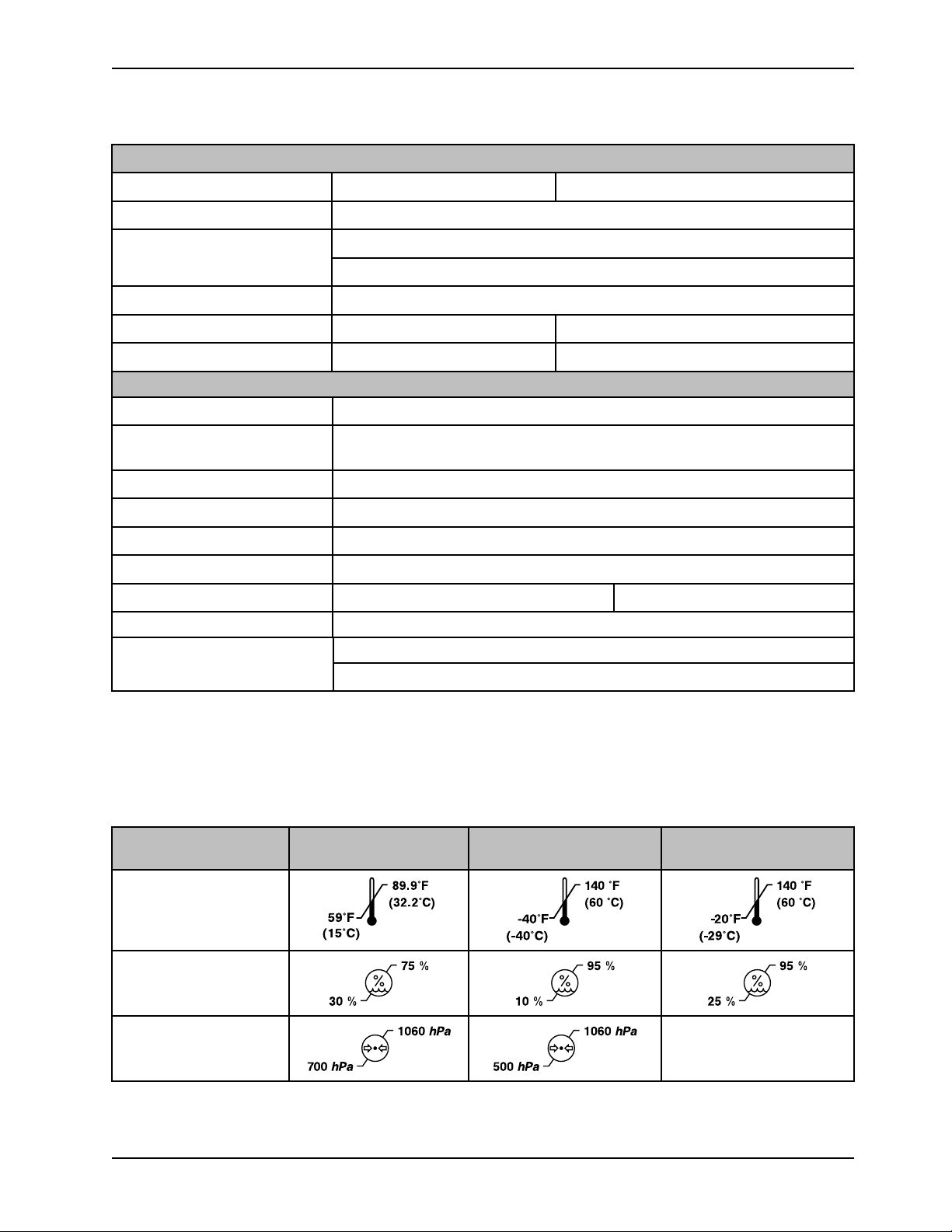
89.9°F
(32.2°C)
59°F
(15°C)
140 °F
(60 °C)
-40°F
(-40°C)
140 °F
(60 °C)
-20°F
(-29°C)
75 %
30 %
95 %
10 %
95 %
25 %
1060 hPa
700 hPa
1060 hPa
500 hPa
Patient temperature
Introduction
Control setting range
89.6° - 100.4° F
32.0° - 38.0° C
Control accuracy ±0.1° C (32° - 38° C)
Measurement accuracy
±0.3° C (25.0° - 45.0° C)
±0.4° C (0.0° C - 24.9° C, 45.1° C - 50.0° C)
Display / resolution setting
Display range 32.0° - 122.0° F
Default setting
0.1° C
98.6° F
0.0° - 50.0° C
37.0° C
Controller
Heater capacity, maximum 500 watts
Circulating fluid Sterile distilled water or water that has been passed through a filter less than or
equal to 0.22 microns with this product
Battery 9V Lithium
Alarm tone range
Water flow rate in each hose port
Refrigerant type
Power cord length
Clinical thermometer
75 - 85 dBA per standard IEC 60601-1-8
Typical 1.2 lpm
R134a
14 to 15 feet
Direct mode
4.2 - 4.5 meters
Equipment Class Class I
Rated for continuous operation
Note: The controller takes approximately 9 minutes to heat from 23.0±2° C (73.4° F) to 37.0° C (98.6° F) when not
connected to a patient. Time will vary when connected to a patient.
Stryker reserves the right to change specifications without notice.
For more information about thermal transfer devices, cables, or probes, see the manufacturer’s instructions for use.
Environmental
conditions
Operation Storage Transporta tion
Ambient temperature
Relative humidity (noncondensing)
Atmospheric pressure
www.stryker.com 8001-009-0 01 REV G 9
Not applicable
Page 14
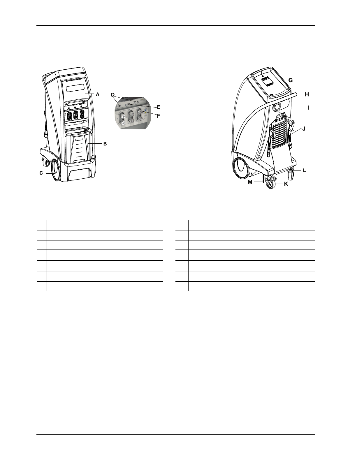
Product illustration
B
C
D
E
F
G
H
I
K
J
L
M
Introduction
Figure 1: Controller, patient front
Figure 2: Controller, patient back
A Storage compartment G Graphical user interface display
B Removable water reservoir H Handle
Front wheels I Power cord
C
D Patient probe ports J Hose and power cord management straps
E Patient temperature output port K
F Hose connection ports L Wheel locks
Swivel casters
M
Ground chain
10 8001-009-0 01 REV G www.stryker.com
Page 15
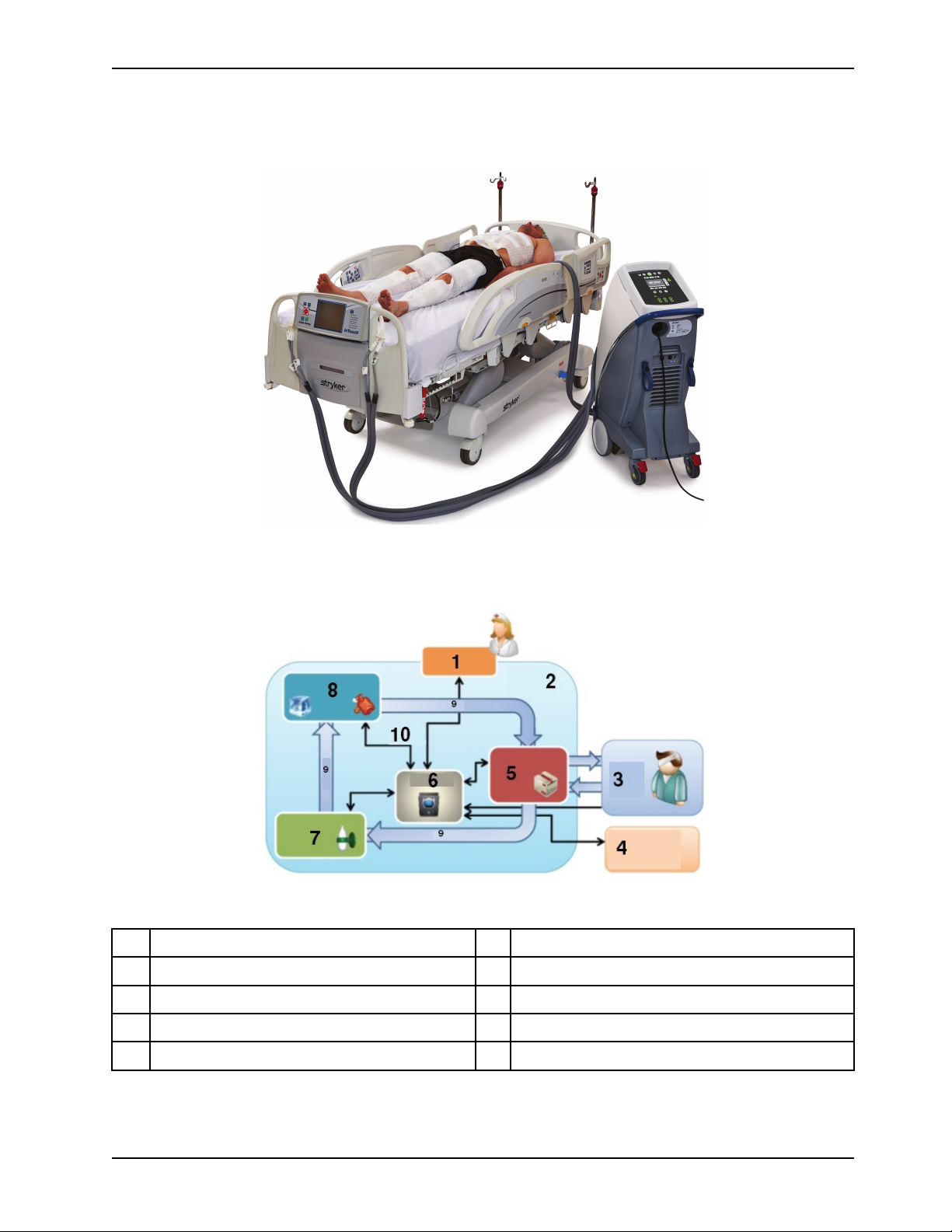
Product system
Introduction
Figure 3: Altrix system - controller with thermal transfer devices
Figure 4: Closed loop system
1
Human machine interface (HMI) system
2 Physical boundary
3 Patient system 8
6
Controls
7
Flow system
Energy transfer system
4
Patient temperature port 9
5
Fluid delivery system 10
www.stryker.com 8001-009-0 01 REV G 11
Water flow
Signals
Page 16
Introduction
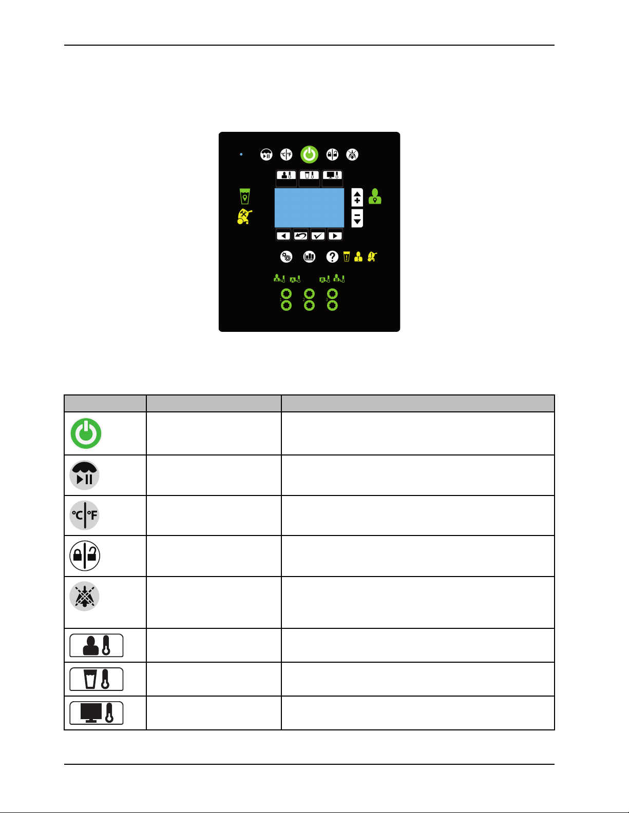
Product functions
The graphical user interface shown is for reference only. The image shows where you will see the icons and buttons
illuminate when they are active. At no time will you see all of these icons at the same time.
Buttons
The buttons are located on the outside of the graphical user interface. They are visible when available.
Icon Name Function
Stand-by Press and hold the button for two seconds to stop therapy or
power off
Therapy paused
View temperature
Lock / unlock screen
Audio paused Pause or resume the audible indicator when an alarm is active.
Automatic therapy mode
Press and hold the button for two seconds to pause or resume
therapy
Select temperature degree in Celsius or Fahrenheit
Press and hold the button for two seconds to lock or unlock the
graphical user interface
Silences each alarm for five or ten minutes depending on the
alarm condition. This button breathes¹ to indicate that it is in a
paused state.
Cools or warms the patient to a selected patient target
temperature
Manual therapy mode
Monitor only mode Displays the current patient temperature (no therapy)
12 8001-009-0 01 REV G www.stryker.com
Cools or warms the water to a selected water target temperature
Page 17
Introduction
Product functions (Continued)
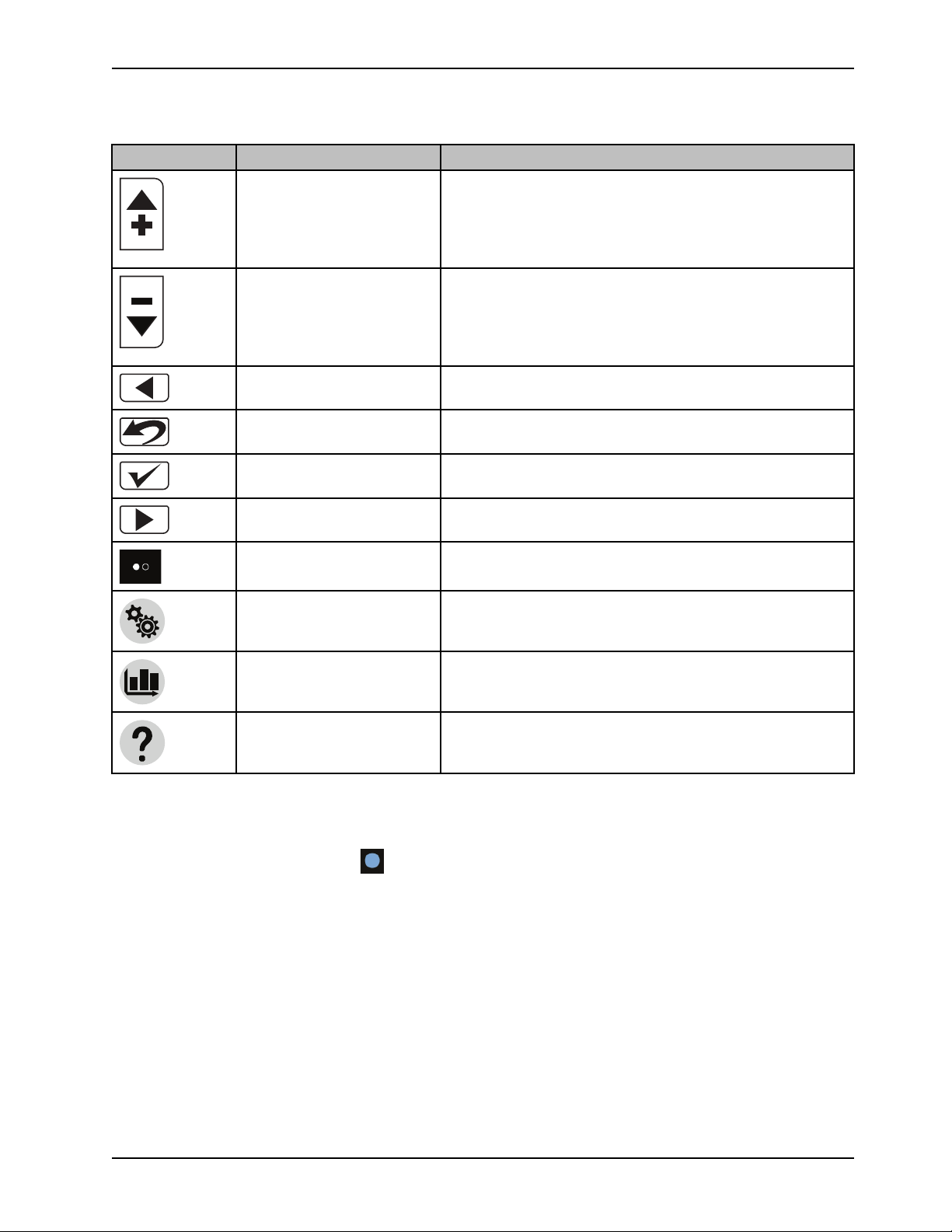
Icon Name Function
Increase
Increases the water or patient temperature by 0.1° for cooling or
warming temperature
Note: Press and hold the increase button to move the
temperature up faster.
Decrease
Back Returns to the previous screen or cancel an operation
Edit settings, Exit, or Cancel
Confirm selection
Next or More Changes to the next screen, option, or setting
Page indicators (may also
appear vertical)
Settings Displays the summary of the current, visual / audible, language,
Graph Graphical display of the selected items such as patient
Help
Decreases the water or patient temperature by 0.1° for cooling or
warming temperature
Note: Press and hold the decrease button to move the
temperature down faster.
Edit current settings, exit, or cancel
Accepts the selected settings
Indicates that there is more than one page associated with the
screen topic for the page that is currently displayed
or primary probe settings
temperature, target temperature, water temperature, and power
level
Displays contextual help screens for therapies, navigation,
buttons, and alarm screens. This button breathes to allow the
user to view the alarm screen.
Note: If not specified above, make sure that you tap and release the buttons or icons for you selection to register with the
system.
Note: The Light sensor (non selectable)
Note: ¹Breathe: The brightness of the button or icon will go to a low light and then increase to a bright light. This cycle
repeats.
, dims or brightens the LCD based on the amount of light in the room.
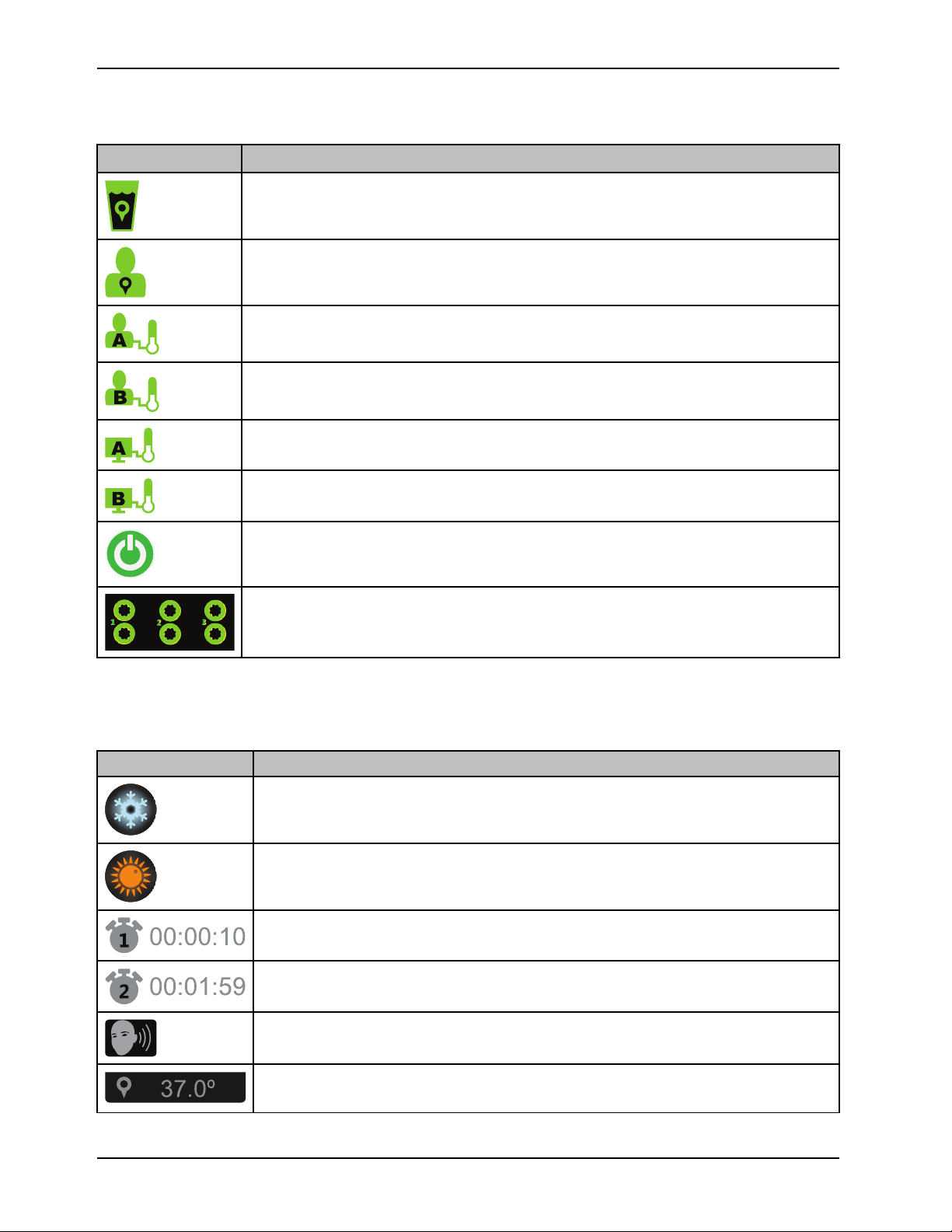
Visual indicators
When the visual indicators are solid green, this indicates that the function is stabilized. The visual indicators breathe to
indicate that the controller is at the intermediate target.
www.stryker.com 8001-009-0 01 REV G 13
Page 18
Product functions (Continued)
3
2
1
1
2
|
|
Icon, green Name
Water temperature on target, solid green when active, does not breathe
Patient temperature on target
Patient probe A port, stabilized
Patient probe B port, stabilized
External device, patient probe A
External device, patient probe B
Introduction
Stand-by
Water flow detected, ports 1, 2, or 3 are active, solid green when active, does not breathe
Graphical user interface icons
Icon Name
Cooling therapy
Warming therapy
Current therapy duration
Total duration
14 8001-009-0 01 REV G www.stryker.com
Visual and audible tests
Target patient or water temperature
Page 19
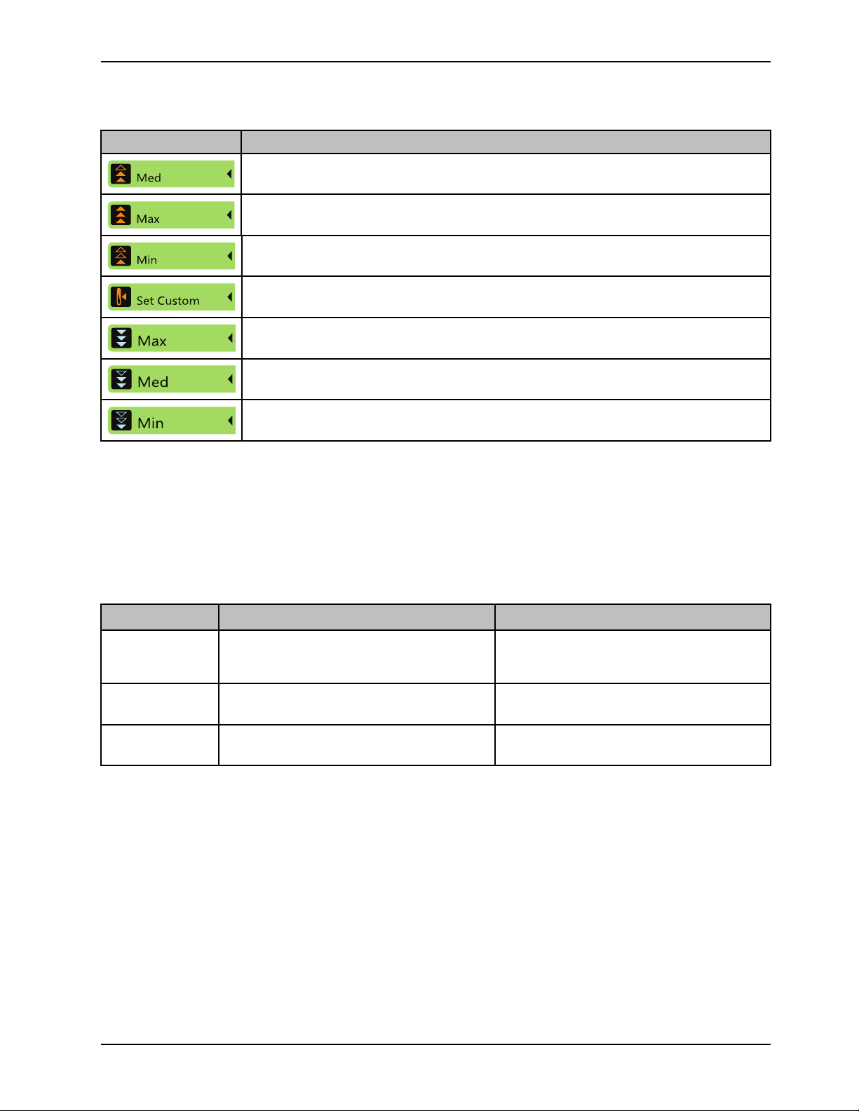
Product functions (Continued)
Med
Max
Min
Set Custom
Max
Med
Min
Icon Name
Medium: patient temperature increases at a rate of 4.0° C in 12 hours (0.33° C/ hour).
Maximum: water temperature approaches water target as fast as possible
Minimum: patient temperature increases at a rate of 4.0° C in 24 hours (0.17° C/hour).
Set Custom: patient temperature increases at a customized temperature and time period the
operator selects. The temperature increases 0.05° C/hour to 0.5° C/hour
Maximum: water temperature approaches water target as fast as possible
Medium: water is cooled to target, with a max of 15.0° C difference between the patient and
the water temperature
Minimum: water is cooled to target, with a max of 10.0° C difference between the patient and
the water temperature
Introduction
Product alarms
Audible alarms work in conjunction with the display.
Alarm priority and description
Priority alarm Audible reminder Icon flashes
Medium
Low
Audio pause Button breathes as a reminder
Note: You can pause the audio alarm. The alarm will resume within five to ten minutes or sooner, if not resolved. The
alarm will resume depending on when the alarms became active and the number of active alarms.
Repetitive burst of three beeps every 25
seconds
Single burst of two beeps The icon does not flash when there is a low
When a medium priority alarms, the icon will
flash to indicate there is an alarm. It will
continue to flash until the alarm is resolved.
priority alarm.
Pausing the alarm will not stop the icon from
flashing.
www.stryker.com 8001-009-0 01 REV G 15
Page 20

Product alarms (Continued)
Introduction
Icon, yellow Name Alarm priority
and delay
Water
temperature
deviation
No water Medium, 20
No water flow
Check water flow
on any port
Medium Water
second delay
Medium, 20
second delay
Medium, 60
second delay
Message Therapy
interrupted
No Temporary
temperature is
±0.8° C (1.4° F)
outside of target
temperature
No water Yes
No flow detected
Reduced flow
detected
Yes
No
Check
condition upon
startup, addition
of thermal
transfer device,
or addition of
water
Check for leaks
Add a minimum
of 2 liters of
water
Check for leaks
and obstructions
at connections,
hoses, and
thermal transfer
devices
Tap Confirm, if
the water port
was removed
intentionally
Check for leaks
and obstructions
at connections,
hoses, and
thermal transfer
devices
16 8001-009-0 01 REV G www.stryker.com
Page 21

Product alarms (Continued)
Introduction
Icon, yellow Name Alarm priority
and delay
Check patient
probe (A or B)
Probe or adapter
malfunction (A or
B)
Adapter cable
disconnected (A
or B)
Patient
temperature
deviation
Medium Abnormal change
Medium, 30
second delay
Medium, 30
second delay
Medium Patient
Message Therapy
interrupted
Yes
in patient
temperature
No temperature
signal detected.
Adapter cable not
detected
temperature is ±
0.5° C (0.9° F)
outside of target
temperature
(Only will appear
after the initial
target is reached.)
Yes
Yes Reinsert the
No Check patient
Check
Check probe
condition,
location, and
connections
Check probe or
adapter cable
condition,
location, and
connections
adapter cable. If
damaged,
replace the
adapter cable
condition,
placement of
thermal transfer
devices, and all
connections
Normothermia
deviation
Therapy pause Medium Therapy is
Battery low Low Battery is low No Maintenance is
Patient
temperature
output (A or B)
Low Patient
temperature is
outside of 36.0° C
(96.8° F) to 38.0°
C (100.4° F)
currently paused
Low Patient
temperature
output is
inaccurate on the
external device,
or outside
supported range
No
Yes To resume, press
No
Check patient
condition,
placement of
thermal transfer
devices, and all
connections
and hold the play
/ pause for 2
seconds
recommended. If
battery is not
replaced, the
product may not
function on the
next startup.
Check output
adapter cable
connection. Tap
Confirm to
reactivate the
output port.
www.stryker.com 8001-009-0 01 REV G 17
Page 22
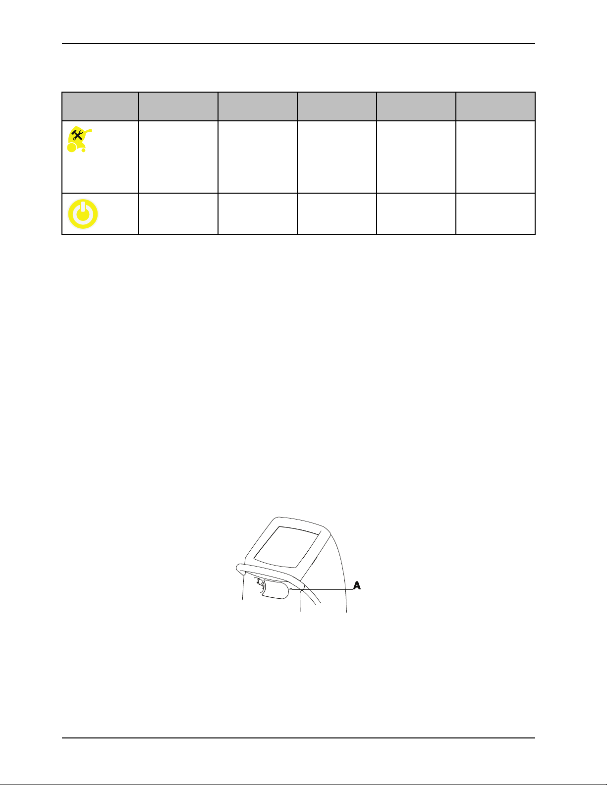
Product alarms (Continued)
A
Introduction
Icon, yellow Name Alarm priority
and delay
Remove from use
(RFU)
Power loss Medium Not applicable Yes
Notes
• If any of the alarm conditions persist, call maintenance.
• If page indicators appear on the alarm screen, there are multiple active alarms. The highest alarm is displayed. Tap
Next or Back to view the active alarms.
Medium The system has
Message Therapy
interrupted
Yes Remove the
powered off due
to a malfunction
Check
product from use
immediately.
Notify the
appropriate
personnel.
Check power
cord connection
Contact information
Contact Stryker Customer Service or Technical Support at: 1-800-327-0770.
Stryker Medical
3800 E. Centre Avenue
Portage, MI 49002
USA
To view your operations or maintenance manual online, see https://techweb.stryker.com/.
Have the serial number (A) of your Stryker product available when calling Stryker Customer Service or Technical Support.
Include the serial number in all written communication.
Serial number location
Date of manufacture
The year of manufacture is the first four digits of the serial number.
18 8001-009-0 01 REV G www.stryker.com
Page 23

Setup
Unpack the cartons and check all items. Make sure that the product is free from visual damage before putting into
service.
CAUTION
• Shock Hazard - Improper handling of the power cord may damage the power cord and cause potential shock
hazards. If damage has occurred to the power cord, immediately remove the temperature management system from
service to avoid the risk of serious injury or death. Contact the appropriate maintenance personnel.
• Take special precautions regarding electromagnetic compatibility (EMC) when using medical electrical equipment
like Altrix. Install and place Altrix into service according to the EMC information located in the EMC section of this
manual. Portable and mobile RF communications equipment can affect the function of Altrix.
• Shock Hazard. If the internal electrical components are exposed, because the side panel or cover are compromised,
remove the product from use.
• Always make sure that the product reaches room temperature before you setup or operate the product.
• Before first use, disinfect the internal water circuit.
Inspecting
Before you place the product into service, make sure that the controller works.
1. Visually inspect the product for any signs of shipping damage.
2. Plug the product into a properly grounded, hospital grade wall receptacle. Make sure that the power indicator
illuminates on the operator control panel.
3. Before first use, .Disinfect the internal water circuit and hoses every 14 days on page 39
Selecting a language
The Altrix controller has several language choices. English is the default language.
To select a language when in standby mode:
1. Tap the Settings button, to show the Select Language screen.
a. Tap Next, if you are in therapy mode.
2. Tap More to view other languages.
3. Select a language. Tap on the Increase or Decrease buttons or tap the language, to highlight a language of your
choice.
4. Tap Confirm.
Note: If you do not touch the screen for three minutes, the LCD will return to the previous menu.
Testing visual and audible alarms
Before placing the product into service, make sure that the visual and audible alarms are functioning.
1. Tap the Settings button.
2. Tap the Back button.
3. Tap the Visual/Audible icon.
www.stryker.com 8001-009-0 01 REV G 19
Page 24

Setup
Testing visual and audible alarms (Continued)
4. Tap Confirm.
Notes
• The system runs through visual tests of the Green Indicators, Yellow Indicators, White Indicators, and Fluid
Controller Light tests, and audible alarms.
• The test will continue until you stop it.
5. To stop the Visual / Audible test, tap the Back button.
6. To exit settings, tap the Exit button.
20 8001-009-0 01 REV G www.stryker.com
Page 25

Operation
A
Placing the product
When placing the product, do not block access to the hospital-grade plug or medical-grade wall outlet.
CAUTION
Do not use Altrix located near or stacked with other medical equipment. If it is necessary to locate Altrix near other
medical equipment, make sure it operates as intended.
Place the Altrix controller outside of the patient environment by 1.5 m (4.9 ft) (Figure 5 on page 21).
Figure 5: Product placement
Applying or releasing the wheel locks
The wheel locks are to help keep the product in place. The wheel lock prevents the rear caster wheels from rotating but
does not prevent the product from sliding on the floor surface.
CAUTION
Always apply the wheel locks to prevent unintended movement.
To apply the wheel locks, push down (A) (Figure 6 on page 21) with your foot.
To release the wheel locks, pull up (A) (Figure 6 on page 21) with your foot.
Figure 6: Wheel locks
www.stryker.com 8001-009-0 01 REV G 21
Page 26

Operation
A
B
C
Selecting and connecting a temperature probe
CAUTION
• Do not use high frequency surgical instruments or endocardial catheters while the Altrix system is in use. This is to
avoid the risk of electrical shock, burns, or electromagnetic interference.
• Always use Stryker accessories. Only IEC 60601-1 equipment shall be hooked to the patient temperature ports.
Failure to comply with these instructions may invalidate any or all warranties and may negatively affect the products
EMC performance. This also protects the product from cardiac defibrillation.
Use only Stryker temperature probes. See Patient temperature probes on page 46.
To connect the temperature probe:
1. Inspect the temperature probe and reusable adapter cable for wear, breakage, or fraying. Replace, if necessary.
2. Align the red dot on the Reusable Adapter Cable (B) to the controller (A) with the red dot on the patient probe port A
or port B.
Figure 7: Port selected
3. Connect the plug (C) to the patient temperature probe.
4. Apply the temperature probe to the patient. Follow your hospital protocol and the manufacturer’s directions for the
selected temperature probe use.
5. Tap Confirm, if applicable.
Note: Temperature readings may vary between temperature measurement sites.
Connecting the reusable patient temperature output cable
This feature allows the operator to view the temperature on the Altrix system and on an external device. Always connect
the reusable patient temperature output cable to a 400 series compatible external device for temperature accuracy.
CAUTION
Always use Stryker accessories. Only IEC 60601-1 equipment shall be hooked to the patient temperature ports. Failure to
comply with these instructions may invalidate any or all warranties and may negatively affect the products EMC
performance. This also protects the product from cardiac defibrillation.
22 8001-009-0 01 REV G www.stryker.com
Page 27

Operation
Connecting the reusable patient temperature output cable (Continued)
To connect the reusable patient temperature output cable:
1. Insert the reusable patient temperature output cable into the patient temperature port (Figure 8 on page 23).
Figure 8: Patient temperature output port
2. Connect the other end of the reusable patient temperature output cable to the external device.
Note: When Altrix is powered, the calibration of the patient temperature output is completed.
Note: If you need to calibrate the patient temperature output cable, power cycle the product by removing the plug
from the wall.
Note: For the reusable patient temperature output cable to work properly, make sure that you insert a patient
temperature probe into port A or port B.
3. Tap Confirm.
Connecting the insulated hoses
To connect the insulated hoses:
1. To connect, push back on the retaining collar of the port on the controller (Figure 9 on page 23).
Figure 9: Pull back on the retaining collar
2. Push the hose into an upper or lower port (Figure 10 on page 23) and release the collar until the retaining collar
clicks into place (Figure 11 on page 23).
Note: Connect a set of ports for proper water flow.
Figure 10: Connect the hoses
Figure 11: Hoses connected
www.stryker.com 8001-009-0 01 REV G 23
Page 28

Operation
Disconnecting the insulated hoses
To disconnect the insulated hoses:
1. To disconnect, push back on the retaining collar of the port on the controller.
2. Pull the hose to disconnect.
Connecting and disconnecting thermal transfer devices
Read the operations manual for the individual thermal transfer devices for warnings, cautions, and safe operating
instructions before use.
CAUTION
• Avoid the use of materials of good thermal conductivity, such as water, gel, or similar substances, with the Altrix
system not powered on. This can decrease the temperature of the body of a patient.
• Do not apply thermal transfer devices to patients with ischemic limbs. This may result in harm to the patient.
• Do not use this product if the patient has a transdermal medication (patch) as this can result in increased drug
delivery.
• Always use Stryker accessories. Failure to comply with these instructions may invalidate any or all warranties and
may negatively affect the products EMC performance. This also protects the product from cardiac defibrillation.
• Do not use three or more adult Mul-T-Blanket products at the same time to avoid the risk of water overflow when the
controller is powered off.
• Always pre-fill the thermal transfer device with sterile distilled water before you apply it to the patient. This is to
reduce the risk of pressure ulcers.
• Avoid reduction in water flow. Do not connect two or more thermal transfer devices in series on a single port.
• Always clamp the hoses when disconnecting the thermal transfer devices.
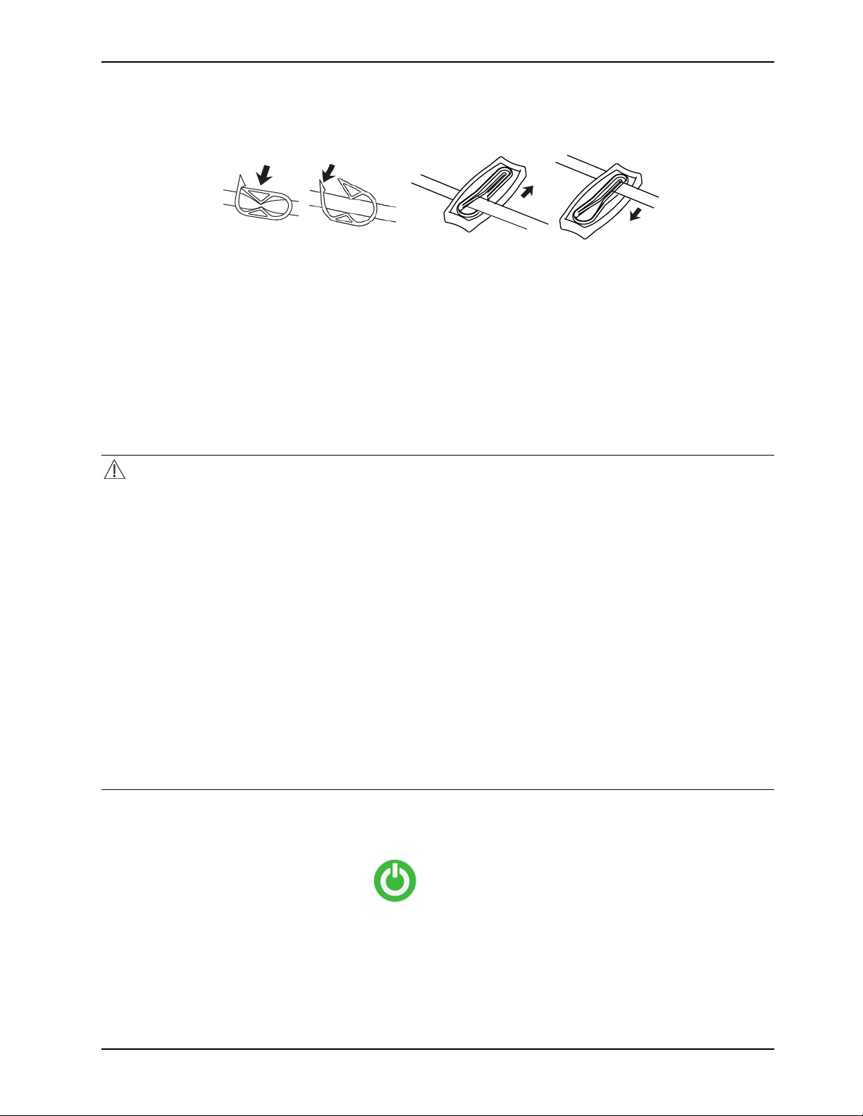
To connect or disconnect the Clik-Tite® connectors (Figure 12 on page 24) to the insulated hoses.
Figure 12: Clik-Tite
To connect or disconnect the Colder style (Figure 13 on page 24) to the insulated hoses.
Figure 13: Colder style connectors
To close or open hose clamps (Figure 14 on page 25).
24 8001-009-0 01 REV G www.stryker.com
Page 29
Operation
Connecting and disconnecting thermal transfer devices (Continued)
Figure 14: Hose clamps
Note: The term “thermal transfer devices” is used throughout this manual and is interchangeable with blankets and
wraps, unless indicated otherwise.
Always clamp the hoses before disconnecting. See Draining the thermal transfer devices on page 33.
Powering on the product
The operator should stand in front of the controller within arm’s reach. This allows the operator to see and respond to the
display notifications.
CAUTION
• Shock Hazard. Improper handling of the power cord may damage the power cord and cause potential shock hazards.
If damage has occurred to the power cord, immediately remove the Altrix system from service to avoid the risk of
serious injury or death. Contact the appropriate maintenance personnel.
• Electric shock. This equipment must only be connected to a supply mains with protective earth.
• Always plug this product directly into a properly grounded hospital-grade or medical-grade wall outlet to achieve
grounding reliability.
• Do not use high frequency surgical instruments or endocardial catheters while the Altrix system is in use. This is to
avoid the risk of electrical shock, burns, or electromagnetic interference.
• Explosion risk. This product is not suitable for use in the presence of flammable anesthetic mixture with air or with
oxygen or nitrous oxide other than nasal or mask type.
• Do not place cables, hoses, or power cord in walkways to avoid the risk of trip hazards.
• Avoid reduction in water flow. Do not connect two or more thermal transfer devices in a series on a single port.
• Do not use three or more adult Mul-T-Blanket’s at the same time to avoid the risk of water overflow when you power
off the controller.
• When you operate the product near ambient temperature limitations of 15.0° C (59.0° F) or 32.0° C (89.6° F), you
may experience a reduction in product performance.
To start the product:
1. Plug the power cord into a wall outlet.
2. Tap the Stand-by button to start the product.
3. If you are going into Automatic mode or Monitor mode, see Selecting and setting the primary probe on page 27. If
manual mode, got to the next step.
4. See Removing and replacing the reservoir on page 26.
5. See Filling the reservoir with sterile distilled water on page 26.
6. Connect up to three thermal transfer devices (with the exception of adult Mul-T-Blankets) to dedicated adapter
hoses and ports.
www.stryker.com 8001-009-0 01 REV G 25
Page 30

Operation
A
B
C
Powering on the product (Continued)
7. Open the clamps on the connector hose and the thermal transfer devices to provide proper water flow.
8. See Filling a thermal transfer device on page 28.
9. See Selecting a therapy mode on page 28.
10. Make sure that the desired port configuration is maintained and that water is flowing through the thermal transfer
devices.
WARNING
Always turn or re-position the patient over the duration of therapy, if possible, to reduce the risk of pressure ulcers.
Follow your hospital protocol.
Removing and replacing the reservoir
The removable reservoir enables you to fill or drain the reservoir away from the controller without interrupting therapy.
You will need to have the reservoir installed before starting a therapy.
CAUTION
Do not place your fingers in between the reservoir and the sides of the controller, to avoid the risk of pinching your fingers.
To remove the reservoir, pull forward at an angle, and lift out the reservoir (Figure 15 on page 26).
Figure 15: Removable reservoir
1. To replace the reservoir, align the base of the reservoir over the drain (C).
2. Align the notch on the back of the reservoir (A) with the hook on the controller (B) (Figure 15 on page 26)
3. Push the reservoir back into place. Make sure that the reservoir is secure to avoid water leakage.
Filling the reservoir with sterile distilled water
The removable reservoir is translucent for you to see the water levels.
26 8001-009-0 01 REV G www.stryker.com
Page 31
Operation
A
Filling the reservoir with sterile distilled water (Continued)
CAUTION
• Always use sterile distilled water or water that has been passed through a filter less than or equal to 0.22 microns
with this product.
• Always fill the reservoir with room temperature sterile distilled water to reduce the risk of burn.
• Do not overfill the reservoir to avoid the risk of water spillage and fall.
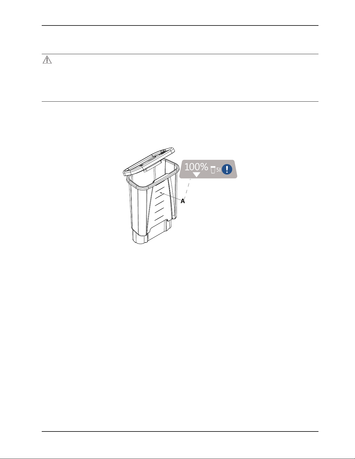
To fill the removable reservoir with sterile distilled water:
1. See Removing and replacing the reservoir on page 26.
2. Fill the reservoir with five liters of sterile distilled water. Do not fill past the top fill line to avoid water overflow (Figure
16 on page 27).
Figure 16: Reservoir fill lines
Selecting and setting the primary probe
A patient probe displays when present, stable, and confirmed. The choice of Probe A or Probe B is highlighted when you
insert the cable into port A and port B. If you only insert one cable, the active port displays.
1. Tap the Settings button.
a. In the standby mode, tap the Back button to display the edit settings screen.
b. In an active therapy mode, tap the Next button.
2. Tap Select Probe to display the Select Primary Probe (Probe A or Probe B) screen. If both probes are present, the
default is probe A.
3. Tap A or B, if applicable.
4. Tap Confirm.
Notes
• The message “Probe stabilization in progress... Please wait” is displayed.
• When you initially select a probe (A or B), detected is checked. When stabilized, the Ready check is displayed.
• If the probe is not stabilized within three minutes, the message “Probe stabilization error” will appear. Tap the
Help button for more detail.
• You can select help at any time to display help with the current screen or icon descriptions.
www.stryker.com 8001-009-0 01 REV G 27
Page 32

Operation
Filling a thermal transfer device
CAUTION
Always pre-fill the thermal transfer device with sterile distilled water before you apply it to the patient. This is to reduce
the risk of pressure ulcers.
Note: These instructions are to pre-fill the thermal transfer devices only, not therapy. See Switching modes on page 31.
To fill a thermal transfer device:
1. Connect a thermal transfer device following: Connecting and disconnecting thermal transfer devices on page 24.
2. Lay the thermal transfer device on a flat surface. Make sure the thermal transfer device is flat for water flow.
3. Open all of the clamps on the connector hose and thermal transfer device.
4. Make sure that the controller is powered.
5. Tap the Stand-by button.
6. Tap the Manual mode button.
7. Tap Confirm.
8. Select a water temperature that aligns with your target patient temperature.
Note: Allow the water to flow from the controller into the thermal transfer device until full.
9. Tap Confirm.
Selecting a therapy mode
You can select from one of three therapy modes and tap Confirm:
• Automatic therapy
• Manual therapy
• Monitor non-therapy
For mode descriptions, tap the Help button.
WARNING
Always check the integrity of the patients skin and temperature according to hospital protocol when using the Altrix
system.
CAUTION
• Explosion risk. This product is not suitable for use in the presence of flammable anesthetic mixture with air or with
oxygen or nitrous oxide other than nasal or mask type.
• Always make sure that there are no water leaks before starting a defibrillation.
• When using the temperature controlled Automatic therapy mode for warming (min, med, or custom), switching to
other modes, changing the target patient temperature, or changing the therapy selection may impact the overall
benefit of therapy.
• Always use Stryker accessories. Failure to comply with these instructions may invalidate any or all warranties and
may negatively affect the products EMC performance. This also protects the product from cardiac defibrillation.
• Always monitor the patient for shivering, temperature, signs of intolerance, and skin condition when using this
product.
• Always pre-fill the thermal transfer devices with water before applying to the patient.
28 8001-009-0 01 REV G www.stryker.com
Page 33

Operation
Max
Med
Min
Starting Automatic therapy mode
In Automatic mode, the therapy cools or warms the patient to a selected patient target temperature. The product in
automatic mode continually measures the patient temperature and automatically adjusts the water temperature until the
selected patient target temperature is achieved. After the selected patient target temperature is achieved, the product
maintains this temperature for the duration of the therapy.
To start Automatic therapy mode:
1. Prepare the thermal transfer devices for therapy.
2. See Filling a thermal transfer device on page 28.
3. Apply the thermal transfer device to the patient.
4. Connect the reusable adapter cable to port A or port B on the product. Make sure that the probe is fully seated.
5. Apply the sensing end of a patient probe to the patient based on your hospital protocol and secure the product to
reduce the risk of accidental dislodgment.
6. Connect the patient temperature probe to the reusable adapter cable. See Selecting and connecting a temperature
probe on page 22.
7. Tap to Confirm the current patient temperature.
8. Tap the Automatic therapy mode button.
9. Select the target patient temperature.
10. See Setting or editing the cooling rates on page 29 or Setting or editing the warming rates on page 30
Notes
• The controller determines Warming or Cooling therapy based on the selected water target temperature and the
current water temperature.
• Do not place additional heat sources between the patient and thermal transfer device.
• After the patient target temperature is achieved, patient temperature is controlled within +/-0.3° C.
• If the patient temperature is not within 0.5° C of the current target temperature, the yellow patient icon will flash
and the patient temperature deviation alarm will sound. This occurs after the initial patient target temperature is
achieved.
Setting or editing the cooling rates
Setting cooling rates is for Automatic Mode only.
1. To set the cooling temperature, highlight your choice of cooling rates.
Select a cooling rate
2. Tap Confirm.
3. Tap the Edit button to make changes.
Description
Maximum: approaches patient target temperature as fast as possible
Medium: water is cooled to target, with a max of 15.0° C difference between the
patient and the water temperature
Minimum: water is cooled to target, with a max of 10.0° C difference between the
patient and the water temperature
www.stryker.com 8001-009-0 01 REV G 29
Page 34

Operation
Max
Med
Min
Set Custom
rr
Setting or editing the warming rates
Setting warming rates is for Automatic Mode only.
1. To set the warming temperature, highlight your choice of warming rates.
Select a warming rate Description
Maximum: approaches patient target temperature as fast as possible
Medium: patient temperature increases at a rate of 4.0° C in 12 hours (0.33° C/ hour).
Minimum: patient temperature increases at a rate of 4.0° C in 24 hours (0.17° C/hour).
Set Custom: patient temperature increases at a customized temperature and time
period the operator selects. The temperature increases 0.05° C/hour to 0.5° C/hour.
2. If you select Set Custom, tap the Increase and Decrease buttons to set the rate (Figure 17 on page 30).
Figure 17: Set custom warming rate
3. Tap Confirm.
4. Tap the Edit button to make changes.
Starting Manual mode
In Manual mode, the therapy will cool or warm the water to a selected water target temperature. The operator must
observe the patient’s temperature and manually adjust the water temperature to obtain the desired patient temperature.
1. If desired, select and place the sensing end of the patient probe based on hospital protocol. Connect the reusable
adapter cable to port A or port B on the product. See Selecting and connecting a temperature probe on page 22.
2. Prepare the thermal transfer devices to be used for therapy.
3. See Filling a thermal transfer device on page 28.
4. Apply the thermal transfer device to the patient.
5. Tap Manual mode. The default water target temperature is 40.0° C (104.0° F) upon initial entry.
6. Tap Confirm.
7. To select the desired water temperature, tap the Increase or Decrease buttons or hold the button to go faster.
a. To edit water temperature, tap the Edit button.
8. Tap Confirm.
30 8001-009-0 01 REV G www.stryker.com
Page 35

Operation
Starting Manual mode (Continued)
Notes
• The controller determines Warming or Cooling therapy based on the selected water target temperature and the
current water temperature.
• In Manual mode, only the water temperature is controlled.
• A temperature probe is not required when operating in Manual mode.
• After the water target temperature is achieved, water temperature is controlled within +/-0.3° C.
Starting Monitor mode
In Monitor mode, no therapy will be delivered, only a display of the current patient temperature.
To start Monitor mode:
1. Connect the reusable adapter cable to port A or port B on the controller. Make sure that the probe is fully seated.
2. Apply the sensing end of patient probe to patient based on hospital protocol. Secure the patient probe to reduce the
risk of accidental dislodgment.
3. Tap the Monitor button.
4. Connect the patient temperature probe to the end of the reusable adapter cable. See Selecting and connecting a
temperature probe on page 22.
Note: If the product senses a patient probe temperature below 36.0° C (96.8° F) or above 38.0° C (104° F), the
normothermia alarm displays and an audible alarm sounds.
5. Tap Confirm. The screen will display the current patient temperature.
Switching modes
Tap Edit and select a different therapy mode.
Pausing and resuming therapy
To pause therapy, press and hold the Pause Therapy button for two seconds.
To resume therapy, press and hold the Pause Therapy button for two seconds.
Displaying the data storage
The system gathers data at five second intervals and is limited to 90 minutes of storage. The graphical display defaults to
show data for all four variables in the Manual and Automatic modes.
www.stryker.com 8001-009-0 01 REV G 31
Page 36

Operation
0
8.0°C
35.4°C
A
B
C
D
Displaying the data storage (Continued)
To display the patient data graph:
1. Tap the Graph icon.
Figure 18: Graphical display
• Primary patient temperature reading from attached probe (A) (Figure 18 on page 32)
• Intermediate target temperature (B)
• Water temperature (C)
• Power level (D)
2. To view data values, hide values, or data lines, tap an icon until the data you desire appears for the selected icon.
3. Tap next to see the current values for each variable.
4. To exit, tap the Graph icon or the Exit button.
Notes
• In monitor mode, only the patient temperature data is displayed (A).
• The graph icon is only available when a therapy is active.
• The patient data remains until the product sleeps or you powered off the product.
• During a power loss the data is lost and not retrievable.
Opening and securing items in the storage compartment
The storage compartment holds a maximum of 3 lb (1.36 kg).
To open the storage compartment door, lift up on the door (Figure 19 on page 33).
The storage compartment secures the following items:
• Two patient probes
• Two reusable adapter cables
• One reusable patient temperature output cable
• Product operations manual
32 8001-009-0 01 REV G www.stryker.com
Page 37

Operation
Opening and securing items in the storage compartment (Continued)
Figure 19: Storage compartment
Notes
• Make sure that the items are securely inside the compartment and not blocking the magnets.
• When closing the storage compartment door, do not place your fingers between the storage compartment door and
the sides of the controller.
Stopping therapy or powering off the product
To stop therapy or power off the controller:
1. Press and hold the Stand-by button for two seconds.
2. Unplug the product from the wall outlet.
Note: If storing the product, see Storing the controller on page 35.
Draining the thermal transfer devices
Read the manufacturer’s operations manual for the individual thermal transfer devices (blankets and wraps) for warnings,
cautions, and safe operating instructions before use. Make sure that you drain the hoses before you put them in storage.
1. Unplug the product.
2. Remove the thermal transfer device from the patient.
3. Open the clamps on the hoses and thermal transfer devices, if applicable. See Figure 14 on page 25.
4. Raise the thermal transfer devices attached to the hose above the ports on the controller. Gravity helps to drain the
water into the controller.
5. Allow most of the water to drain back into the controller. (Approximately 10 minutes).
6. See Connecting and disconnecting thermal transfer devices on page 24.
7. See Disconnecting the insulated hoses on page 24.
8. See Storing the power cord and hoses on page 35.
9. Discard the disposable thermal transfer devices based on your local waste management protocol.
a. Discard the disposable thermal transfer devices based on your local waste management protocol, if applicable.
Draining water from the reservoir
To drain the water from the reservoir:
1. See Removing and replacing the reservoir on page 26.
2. Dispose of the water per hospital protocol.
www.stryker.com 8001-009-0 01 REV G 33
Page 38

Operation
A
Draining water from the reservoir (Continued)
3. Replace the reservoir.
Note: Make sure that the reservoir is dry before you store the product.
Draining water from the controller and hoses
Make sure that the controller and all components are dry before you store the product. Make sure to drain the hoses
before you store them.
1. Place the controller over a floor drain.
2. Remove the reservoir and pull up on the controller drain plug (A) to open the drain (Figure 20 on page 34).
Figure 20: Drain plug
3. Connect a hose to each port.
a. If you have Colder style connector hoses, attach the service tool adapter hose (8001-999-017).
b. If you have Clik-Tite hoses, make sure that the connectors and clamps are open (Figure 21 on page 34).
Figure 21: Clik-Tite open
4. Raise all the hoses completely above the connection ports on the controller.
5. Allow the product to drain for a minimum of two minutes.
6. Push down on the drain plug to close the drain.
7. Replace the reservoir.
34 8001-009-0 01 REV G www.stryker.com
Page 39

Operation
Storing the power cord and hoses
After you complete therapy or when you transport the product, store the power cord and hoses.
CAUTION
• Do not hang items on the controller handle to avoid the risk of tipping the product.
• Always store the power cord, cables, and hoses before you transport the product to reduce the risk of trip hazard.
To store the power cord and hoses:
1. Connect the ends of the connector hoses together, if applicable.
2. Coil and fasten the hose with the management straps (Figure 22 on page 35).
3. Unplug the power cord from the wall outlet and store with the management straps (Figure 22 on page 35).
Figure 22: Management straps
Storing the controller
Storage is equal to or greater than 7 days without use.
CAUTION
• Do not store the product with water in the device.
• Always store the product within the specified environmental condition values.
To store the controller:
1. See Disinfect the internal water circuit and hoses every 14 days on page 39.
2. See Draining the thermal transfer devices on page 33.
3. See Cleaning the external surfaces on page 37.
4. See Disinfecting external surfaces on page 38.
Notes
• Always bring the controller to room temperature after high or low temperature storage.
• Always store the controller with the reservoir in place.
www.stryker.com 8001-009-0 01 REV G 35
Page 40

Operation
Transporting the product
Make sure to follow these procedures for transporting the product to avoid the risk of possible injury or equipment
damage.
CAUTION
• Always use extra care when you transport the product long distances and on inclines greater than five degrees. Ask
for help, if necessary, to avoid the risk of tipping.
• Always use the handle to move the product. Do not attempt to move the product by pulling on cables, hoses, or by
any other means.
• Avoid ramps that are steeper than ten degrees to avoid tipping the product.
• Do not hang items on the controller handle to avoid the risk of tipping the product.
• Always store the power cord, cables, and hoses before you transport the product to reduce the risk of trip hazard.
1. Make sure that the pathway is clear.
2. Unplug the product from the hospital-grade or medical-grade wall outlet. See Storing the power cord and hoses on
page 35.
3. Make sure to place the product with the ports facing the front (Figure 23 on page 36).
Figure 23: Transport position
4. Use the handle to push the product.
5. Limit movement to a slow careful walk.
6. Use two or more operators to move the system on inclines or long distances.
Notes
• Wheel chair ramps are usually less than five degrees.
• The system weighs 150 lb (68.0 kg) when dry. Weight also depends on other items in the storage compartment.
36 8001-009-0 01 REV G www.stryker.com
Page 41

Cleaning
Cleaning the external surfaces
Clean the external surfaces of the controller and system components before each use. System components may be
subject to contamination during use from contact with soiled hands of the user, airborne pathogens, and unexpected or
accidental events. Make sure you remove all visible soils.
CAUTION
Do not power wash this product.
Tools Required:
• Mild soap
• Soft, lint free cloth (2 or more)
Validated mild soap:
• Enzol® Enzymatic Instrument Cleaner by Johnson & Johnson
To clean the external surfaces of the controller and system components:
See Product illustration on page 10 for clarification of product component names and locations.
1. Unplug the power cord from the wall outlet.
2. Apply wheel locks.
3. Undo power cord and hose straps.
4. Unravel and lay out hoses, cables, and power cord.
5. Disconnect the hoses. Push back on the retaining collar of the port on the controller. Pull the hose to disconnect.
6. Disconnect the patient temperature probe cable from the port.
7. Remove the reservoir. Pull forward at an angle, and lift out the reservoir.
8. If necessary, empty the water from the reservoir. Dispose of the water per your hospital protocol.
9. Prepare a mild soap and water solution as described by the manufacture.
10. Wipe the inside and outside of the reservoir and reservoir lid, with a soft, lint free cloth moistened with soap and
water solution.
11. Wipe the hoses and patient temperature probe cables, with a soft, lint free cloth moistened with soap and water
solution.
12. Wipe the controller surfaces while the reservoir is removed with a soft, lint free cloth moistened with soap and water
solution. Also wipe the following system components:
• Hose connectors
• Power cord
• Hose and power cord management straps
• Storage compartment door
• Inside storage compartment
• Graphical user interface display
• Handle
13. Wipe the controller, reservoir and reservoir lid surfaces, and system components with a clean, dry cloth to remove
any excess liquid.
14. Replace the reservoir.
15. Allow the external surfaces of the controller and components to dry thoroughly.
www.stryker.com 8001-009-0 01 REV G 37
Page 42

Disinfecting
Disinfecting external surfaces
Disinfect the external surfaces of the controller and system components before each use. System components may be
subject to contamination during use from contact with soiled hands of the user, airborne pathogens, and unexpected or
accidental events. Follow your hospital protocols for disinfecting the product. Make sure to follow the manufacturer’s
instructions for the disinfectants.
CAUTION
Do not use quaternaries that contain glycol ethers as they may damage the reusable accessories.
Note: If the product is visibly soiled, clean the surface before disinfecting.
Tools Required:
• Personal protection equipment (PPE) as recommended by the disinfectant manufacturer’s instructions
• Soft, lint free cloth (2 or more)
• Disinfectant
• 2 gallons (7.6 L) of sterile distilled water
Recommended disinfectants for the external surface of the controller and system components:
• Quaternary cleaners (active ingredient - ammonium chloride)
• Phenolic cleaners (active ingredient - o-phenylphenol)
• Chlorinated bleach solution ((1 part bleach solution (5.25% sodium hypochlorite) to 100 parts of water which equals
520 ppm available chlorine (40 ml of a 5.25% bleach solution per 4000 ml water))
Validated disinfectants for the external surface of the controller and system components:
• Sodium hypochlorite based - Clorox® Healthcare Bleach Germicidal Cleaner (EPA registration number 56392-7)
To disinfect the external surfaces of the controller and system components:
See Product illustration on page 10 for clarification of product component names and locations.
1. Use PPE as recommended by the disinfectant manufacturer's instructions.
2. Unplug the power cord from the wall outlet.
3. Apply the wheel locks.
4. Unfasten the power cord and hose straps.
5. Unravel and lay out hoses, cables, and power cord.
6. Disconnect the hoses. Push back on the retaining collar of the port on the controller. Pull the hose to disconnect.
7. Disconnect the patient temperature probe cable.
8. Remove the reservoir. Pull forward at an angle, and lift out the reservoir.
9. If necessary, empty the water from the reservoir. Dispose of the water per your hospital protocol.
10. Prepare disinfectant solution as described by the manufacture.
11. Apply disinfectant solution to the inside and outside of the reservoir and reservoir lid, with a soft, lint free cloth
moistened with disinfectant. Reapply disinfectant to cloth as needed.
12. Apply disinfectant solution to the hoses and patient temperature probe cables, with a soft, lint free cloth moistened
with disinfectant. Reapply disinfectant to cloth as needed.
13. Apply disinfectant solution to the controller surfaces while the reservoir is removed with a soft, lint free cloth
moistened with disinfectant. Reapply disinfectant to the cloth as needed. Also wipe the following system components:
• Hose connectors
• Power cord
• Hose and power cord management straps
• Storage compartment door
• Inside storage compartment
38 8001-009-0 01 REV G www.stryker.com
Page 43

Disinfecting
Disinfecting external surfaces (Continued)
• Graphical user interface display
• Handle
14. Follow specified contact time in accordance with the disinfectants manufacturer’s instructions for use.
15. To rinse, wipe the hoses and patient temperature probe cables, with a soft, lint free cloth moistened with sterile
distilled water.
16. To rinse, wipe the controller, reservoir and reservoir lid surfaces, and system components with a lint free cloth
moistened with sterile distilled water.
17. To dry, wipe the controller, reservoir, reservoir lid surfaces, and system components with a clean, dry cloth to
remove any excess liquid.
18. Replace the reservoir.
19. Allow the external surfaces of the controller and components to dry thoroughly.
20. Store the power cord, cables, and hoses.
Disinfect the internal water circuit and hoses every 14 days
Use the BruClean TbC disinfectant tablets by BruClean TbC (EPA registration number 71847-2-106) before first use, at
least every 14 days, and before storage. BruClean TbC has been validated for internal water circuit disinfection. Make
sure that you follow the disinfectant manufacturer’s guidelines to avoid the risk of injury. Failure to follow the
disinfectant’s instructions may void your warranty.
CAUTION
• Always use sterile distilled water or water that has been passed through a filter less than or equal to 0.22 microns
with this product.
• Do not disinfect the internal water system with a thermal transfer device attached as this may cause a leak.
• Do not use bleach or any other cleaning or disinfectant agents for internal circuits. This could result in damage to the
product. Only use approved disinfectant tablets.
• Always drain the product before disinfecting the internal water circuit. Failure to drain the product may reduce the
effectiveness of the disinfection process.
Note: Disinfection of the Altrix internal water system was validated using M. mucogenicum.
Tools Required:
• 2 gallons (7.6 L) of sterile distilled water or water that has been passed through a filter less than or equal to 0.22
microns
• Personal protection equipment (PPE) as recommended by the disinfectant manufacturer’s instructions
• Soft, lint free cloth (2 or more)
• 2 BruClean TbC 13.1 g tablets (Active ingredient NaDCC solution ppm = 1874 mg/L)
Note: BruClean TbC is a blend of 48% sodium dichloroisocyanturate and Adipic Acid with a 5% sodium dodecyl
benzene sulphonate surfactant.
• Service tool adapter hose (8001-999-0 17) for Colder style connector hoses
• Floor drain
See Product illustration on page 10 for clarification of product component names and locations.
Draining the internal water circuit and hoses for disinfection
1. Unplug the power cord from the wall outlet.
2. Place the controller over a floor drain.
www.stryker.com 8001-009-0 01 REV G 39
Page 44
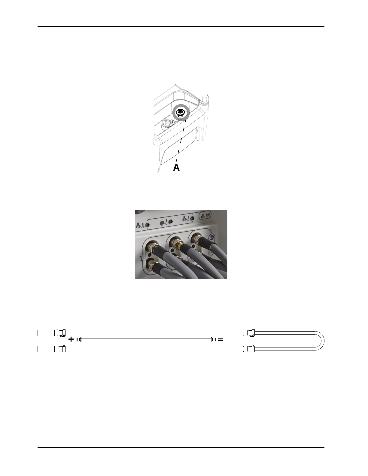
Disinfecting
A
+
=
Draining the internal water circuit and hoses for disinfection (Continued)
Note: For best results, the floor drain should be within reach of a wall outlet to power on the controller.
3. To drain the controller, pull up on the controller drain plug (A) to open the drain (Figure 24 on page 40). Leave the
drain open.
Figure 24: Drain plug
4. Connect a hose to each port (Figure 25 on page 40).
Figure 25: Hoses connected
5. Close the connector ends of all three hoses:
a. If you have Colder style connector hoses, attach the service tool adapter hose (8001-999-017) (Figure 26 on
page 40). Complete this for all three hoses.
Figure 26: Colder style connector hose connected to a tool adapter hose
b. If you have Clik-Tite hoses, make sure that the connector ends are connected and closed (A), and clamps are
open (B). Complete this for all three hoses. Figure 27 on page 41
40 8001-009-0 01 REV G www.stryker.com
Page 45

Disinfecting
A
B
Draining the internal water circuit and hoses for disinfection (Continued)
Figure 27: Clik-Tite hose ends are closed and clamps are open
6. To fully drain the hoses, raise all the hoses (Figure 28 on page 41) above the connection ports on the controller.
Note: For best performance, hang the hoses to keep them raised. Do not lower the hoses until you have
completed the disinfection and rinsing process.
Figure 28: Raise the hoses
7. Allow the controller and hoses to drain for a minimum of two minutes.
8. Push down on the drain plug to close the drain.
Disinfecting the internal water circuit and hoses
1. Use personal protection equipment as recommended by the BruClean TbC disinfectant manufacturer’s instructions
for use.
2. Put 2 BruClean TbC tablets into the reservoir.
3. Using appropriate measuring equipment, fill the empty reservoir with 1 gallon (3.8 L) of sterile-distilled water.
Note: Always allow the disinfectant tablets to completely dissolve before starting the 20 minute disinfection
cycle.
4. Place the reservoir into the controller.
www.stryker.com 8001-009-0 01 REV G 41
Page 46
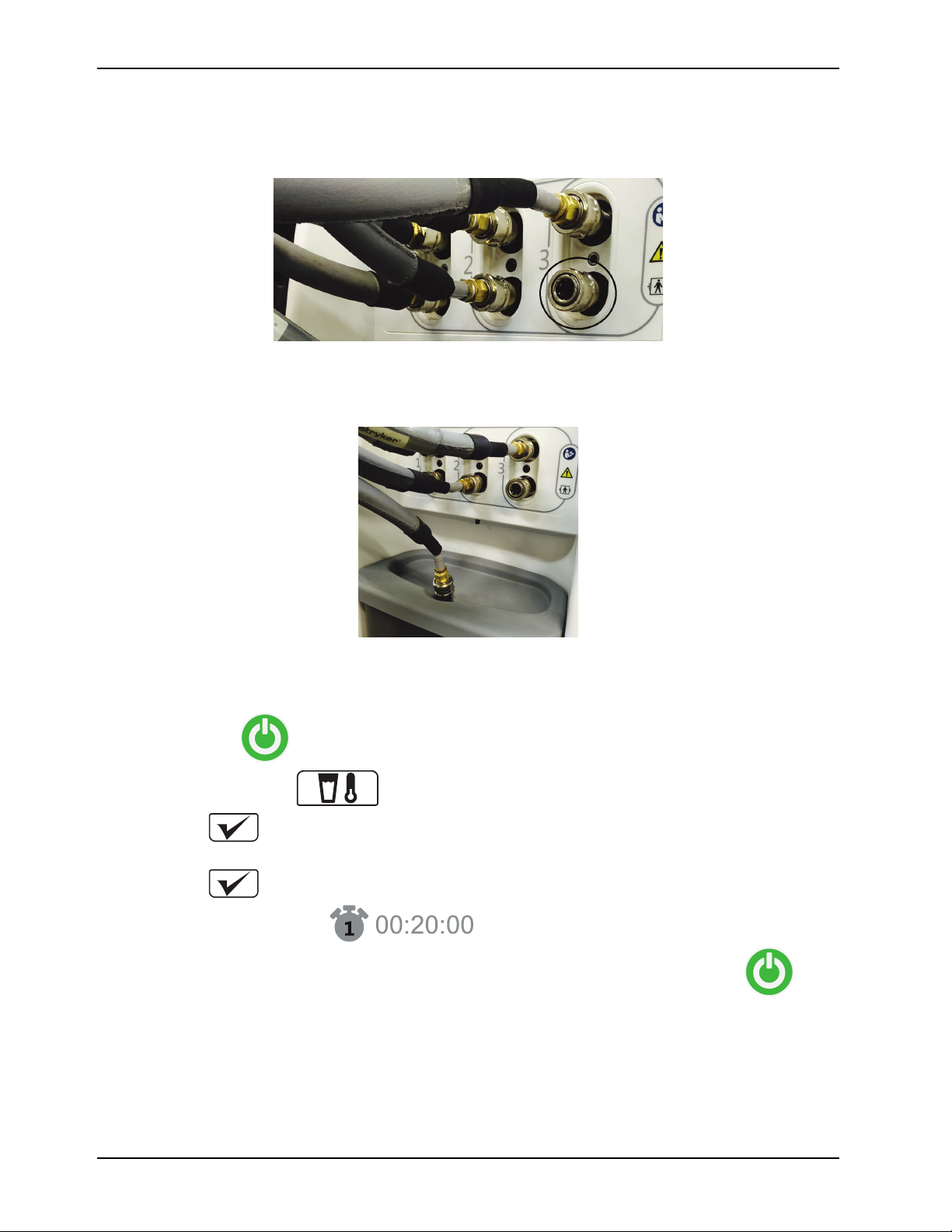
Disinfecting
1
Disinfecting the internal water circuit and hoses (Continued)
5. Disconnect the bottom hose from the bottom right port (Figure 29 on page 42).
Figure 29: Disconnected hose
6. Connect the bottom hose end to the hydraulic connector in the lid of the reservoir (Figure 30 on page 42).
Figure 30: Bottom hose end in the lid of the reservoir
7. Plug the power cord into a wall outlet.
8. Press and hold the
9. Tap the Manual mode icon.
10. Tap Confirm.
11. Set the water target temperature to 25.0° C (77.0° F).
12. Tap Confirm.
13. Run the controller for 20 minutes.
14. After 20 minutes, turn the controller off by pressing and holding the Stand-by button for two seconds.
15. Unplug the power cord from the wall outlet.
16. Place the controller over a floor drain.
17. Remove the reservoir. Pull forward at an angle, and lift out the reservoir.
18. Remove the bottom hose end from the hydraulic connector adapter in the reservoir lid by pushing down on the collar.
19. Empty water from the reservoir, dispose of the water per hospital protocol.
Stand-by button.
42 8001-009-0 01 REV G www.stryker.com
Page 47

Disinfecting
A
Disinfecting the internal water circuit and hoses (Continued)
Note: Do not rinse the reservoir.
20. Pull up on the controller drain plug (Figure 31 on page 43) to open the drain.
Figure 31: Drain plug
21. Make sure that all 3 hoses remain raised above the connection ports for draining.
22. Allow the controller and hoses to drain for a minimum of two minutes.
23. Push down on the controller drain plug to close the drain.
24. When the controller and hoses are drained, continue to Rinsing the internal water circuit and hoses on page 43.
Rinsing the internal water circuit and hoses
1. Using appropriate measuring equipment, fill the empty reservoir with 1 gallons (3.8 L) of sterile-distilled water.
2. Place the reservoir into the controller.
3. Connect the bottom hose end to the hydraulic connector in the lid of the reservoir.
Figure 32: Bottom hose end in the lid of the reservoir
4. Plug the power cord into a wall outlet.
5. Press and hold the
6. Tap the Manual mode icon.
www.stryker.com 8001-009-0 01 REV G 43
Stand-by button.
Page 48

Disinfecting
1
Rinsing the internal water circuit and hoses (Continued)
7. Tap Confirm.
8. Select the water target temperature of 25.0° C (77.0° F).
9. Tap Confirm.
10. Allow the controller to run for 5 minutes.
Note: The timer will run on the main display, follow the current therapy duration timer.
11. After 5 minutes, turn the controller off by pressing and holding the Stand-by button for two seconds.
12. Unplug the power cord from the wall outlet.
13. Place the controller over a floor drain.
14. Remove the reservoir. Pull forward at an angle, and lift out the reservoir.
15. Remove the bottom hose end from the hydraulic connector adapter in the reservoir lid by pushing down on the collar.
16. Empty water from the reservoir, dispose of the water per hospital protocol.
17. Pull up on the controller drain plug to open the drain.
18. Make sure that all 3 hoses remain raised above the connection ports for draining.
19. Allow the controller and hoses to drain for a minimum of two minutes.
20. Push down on the controller drain plug to close the drain.
21. Wipe the inside and outside of the reservoir and reservoir lid, with a dry, soft, lint free cloth.
22. Place the reservoir into the controller.
23. Disconnect and store the service tool adapter hoses from all three of the hoses. (If applicable, when used with
colder style hoses.)
24. Store the power cord, cables, and hoses.
44 8001-009-0 01 REV G www.stryker.com
Page 49

Accessories
Thermal transfer devices
These accessories are currently available for purchase. Not all accessories are available for all regions. Call Stryker
Customer Service at 1-800-327-0770 for availability and pricing. For more information, see the thermal transfer device
instructions for use.
Thermal transfer device
Rapr-Round, small /
medium vest chest
Rapr-Round, large vest
chest
Rapr-Round, leg wrap, one
size for the left or right leg thigh circumference
Mul-T-Blanket, adult
Mul-T-Blanket, pediatric
Rapr-Round, small /
medium vest chest
Rapr-Round, large vest
chest
Rapr-Round, leg wrap, one
size for the left or right leg thigh circumference
Mul-T-Blanket, adult
Mul-T-Blanket, pediatric
Connector type
Clik-Tite
Clik-Tite
Clik-Tite
Colder
Colder
Colder
Colder
Colder
Clik-Tite
Clik-Tite
Part number
8001-061 -530 32 in. to 46 in. 81 cm to 117 cm
8001-061 -535 46 in. to 54 in. 117 cm to 137 cm
8001-061 -540 20.5 in. to 28.5 in. 52 cm to 72 cm
8001-061 -610 25 in. x 64 in. 64 cm x 163 cm
8001-061 -612 22 in. x 33 in. 56 cm x 84 cm
8001-061 -630 32 in. to 46 in. 81 cm to 117 cm
8001-061 -635 46 in. to 54 in. 117 cm to 137 cm
8001-061 -640 20.5 in. to 28.5 in. 52 cm to 72 cm
8001-061 -810 25 in. x 64 in. 64 cm x 163 cm
8001-061 -812 22 in. x 33 in. 56 x 84 cm
Size
Thermal transfer device kits
Kit part number
8001-061-550 8001-061-530
8001-061-560 8001-061-535
8001-061-650 8001-061-630
8001-061-660 8001-061-635
Contents Quantity Type of Connector
8001-061-540 2
8001-061-540 2
8001-061-640 2
8001-061-640 2
1
1
1
1
Clik-Tite
Colder
www.stryker.com 8001-009-0 01 REV G 45
Page 50

Patient temperature probes
Accessories
Patient temperature probes Part Number
Adhesive skin temperature sensing
probe
9FR General purpose temperature
sensing probe
12FR General purpose temperature
sensing probe
14FR Foley catheter temperature
sensing probe
16FR Foley catheter temperature
sensing probe
8001-063 -401 4499
8001-063 -409 4491
8001-063 -412 4492
8001-063 -414 4464
8001-063 -416 4466
Cables
Description Part Number
Reusable adapter cable 8001-064-110
Reusable patient temperature output cable 8001-064-120
Measurement Specialties, Inc.
(MEAS) for Canada only
Hoses
Description Part Number
Insulated Clik-Tite Hose
Insulated Colder Connector Hose
8001-064-035
8001-064-135
46 8001-009-0 01 REV G www.stryker.com
Page 51

Troubleshooting
Problem Possible cause Action Remove from use
Controller will not turn on
Power cord is not plugged
into a properly grounded
hospital grade wall outlet
Insert the plug fully into the
properly grounded hospital
grade wall outlet
If the product does not turn
on after trying a different
outlet
Damaged power cord or
plug
Controller user interface
blackout
Product alarming, user
interface blackout
Temperature probe Not responding, does not
Controller will not heat
Controller will not cool Reservoir is empty Fill reservoir, tap Confirm
Thermal transfer device not
filling with water or ports
not detecting flow
Water level alarm Water level too low Fill reservoir Not applicable
Power outage
Power outage
connect, temperature
outside of range
Reservoir is empty
Locking ring on Clik-Tite
connector is not snapped
into place
Quick disconnect not
seated properly
Visually make sure that the
power cord is not damaged
If the Stand-by button is
solid green, visually inspect
the LCD for damage
If the Stand-by button is
yellow and flashing, visually
inspect the LCD for
damage
Replace temperature probe
Check connections
Fill reservoir, tap Confirm
that water has been added,
restart
that water has been added,
restart
Check the Clik-Tite
connection
Replace the cable or
thermal transfer device
Thermal transfer device
may be to high, lower the
bed level
Thermal transfer device
may be folded, lay flat to
make sure the water flows
Secure the thermal transfer
device connection to the
controller
Replace the cable or
thermal transfer device
If damaged, RFU
If damaged, RFU
If damaged, RFU
If damaged, RFU
If filling the reservoir does
not resolve
If filling the reservoir does
not resolve
Not applicable
Not applicable
www.stryker.com 8001-009-0 01 REV G 47
Page 52

Troubleshooting
Problem Possible cause Action Remove from use
Patient temperature
Out of range Check the placement of the
probe
Not applicable
Patient temperature output
(PTO)
External device output
displays high value >45° C
when input is out of range
(As a result of one of the
following: patient probe
disconnected, controller in
standby / sleep mode,
patient temperature outside
the range of 25° - 45°C).
To resume calibration:
• Disconnect the
external device from
the reusable adapter
cable
• Tap the Help button to
display the alarm
screens
• Find the “Temperature
Output Alarm” screen
• Tap Confirm to restart
calibration
• Wait until the “Monitor”
is solid
• Connect the external
device to the reusable
adapter cable
Not applicable
48 8001-009-0 01 REV G www.stryker.com
Page 53

Preventive maintenance
At a minimum, make sure that all items listed during annual preventive maintenance for all Stryker Medical products.
Preventive maintenance is to be completed by a qualified service technician.
Inspect all of the following items:
Power cord and plug for fraying
Condition of covers and push handle for damage
Hose ports are operational
Ground chain attached
LCD is not cracked
Wheels for smooth operation
Rear caster wheels for free swivel action
Both rear wheels lock securely when the brake is applied
Front and rear wheels are not loose or wobbly
Battery backup functional
Alarm system - visual and audible
LCD functional
Touch screen functional
Water temperature and flow verification
Probe resistance
Clear RFU codes
Ground impedance not more than 100mΩ (millohms)
Current leakage not more than 300 (microamps)
Verify the integrity of all clamps and clamped joints located in the air elimination circuit.
Replace the following on an annual basis:
Replace the 9 volt battery
Replace the condenser inlet filter
Replace the Air eliminator hose
Product Serial Number:
Completed by:
Date:
www.stryker.com 8001-009-0 01 REV G 49
Page 54

Cleaning tools
Description Part Number
BruClean TbC 13.1g tablet, 52 count 8001-999-224
Service tool adapter hose 8001-999-017
50 8001-009-0 01 REV G www.stryker.com
Page 55

Alarm conditions
The alarm rank establishes the order of presentation of the alarm on-screen message. The D in the table indicates the
alarm is deactivated during that mode. Maintenance and RFU modes are always in the deactivated mode and are not
listed in the table.
This product maintains the individual alarm status for all alarms as defined below.
• Alarm condition present
• Visual indicator state
• Audible indicator state
• Current timer for audio pause activation
• Alarm rank per therapy mode
Alarm Stand-by Auto Auto
Paused
Remove from use
Power loss D
Check patient probe
Patient probe malfunction D 6 6 10 10 3
Probe disconnected D
Patient temperature deviation D 9 9 D D D
Water temperature deviation D D D
Check water flow (all ports)
No water flow alarm (all ports)
No water D 2 D 2 D D
Therapy paused timed out D D 3 D 3 D
Normothermia deviation D D D D D
Power backup level
Patient output deviation D 22 22 17 17 7
Notes
• If more than one alarm is active at the same time, the product maintains the active state for the individual alarm
including the audio pause timer. The screen alarms are displayed with the highest level alarm first with a page toggle
to allow the operator to scroll to the subsequent alarms.
• The Paused in Auto Paused and Manual Paused refer to the Therapy Pause state.
0 0 0 0 0 0
1 1 1 1 1
D
D
D
1
7 7 11 11 4
5 5
11
4
19 19
D 6 D D
D
Manual Manual
Paused
9 9 2
7
4
14 14
D D
D D
Monitor
5
6
Check patient probe alarm
This alarm notifies the operator that data provided by the probe is not normal or appears removed.
Notes
• The product only activates the Check Patient Probe Alarm when met during an Active Therapy. Otherwise, the alarm
is disabled.
Alarm generation:
Primary patient temperature changes by more than 1.0° C within two minutes.
Note: The product will deactivate the heat exchange and keep the pump activated as requested by the Active Therapy.
www.stryker.com 8001-009-0 01 REV G 51
Page 56

Alarm conditions
Patient probe malfunction alarm
This alarm notifies the operator that the probe is not providing information to the product during an active therapy.
Alarm generation:
When the primary patient probe is in a shorted, opened condition, or out of range for more than 30 seconds, the product
will display the Patient Probe Malfunction Alarm.
Note: The product will deactivate the heat exchange and keep the pump activated as requested by the Active Therapy.
Patient probe disconnect alarm
This alarm notifies the operator that the probe is not providing information to the product during an active therapy.
Alarm generation:
When the adapter cable for the primary probe is removed and the reading of the Primary Patient probe is out of range for
more than 30 seconds, the product displays the Patient Probe Disconnected alarm.
Patient temperature deviation medium alarm
This alarm notifies the operator that the patient is not responding as expected in the active therapy.
Alarm generation:
The product will display the Patient Temperature Deviation Medium Alarm, if after the initial achievement of the current
patient temperature target, the actual primary patient temperature becomes 0.5° C or more above, or below the Current
Target Temperature.
Patient temperature output deviation alarm
This alarm notifies the operator that the patient temperature output is out of range or their is a calibration error.
Alarm generation:
The product will display the Patient Temperature Output Deviation Alarm, if the calibration has failed, or the patient
temperature output is out of range.
Normothermia deviation alarm
This alarm notifies the operator of that the Primary Patient Temperature is out of range.
Alarm generation:
If the actual Primary Patient Temperat ure is lower or equal to 35.9° C or higher or equal to 38.1° C, the controller will
display the Patient Normothermia Deviation alarm.
Water temperature deviation alarm group
This alarm notifies the operator that the water is not responding as expected to the therapy. The product is at full power,
with the current mode and the temperature selection. The water temperature cannot remain within a range of ±0.8º C of
the selected Water Target Temperature.
52 8001-009-0 01 REV G www.stryker.com
Page 57

Alarm conditions
Water temperature deviation alarm group (Continued)
Alarm generation:
1. If the actual water temperature is 0.8° C or more above or below the Final Target Temperature, the product will
display the Water Temperature Deviation Alarm.
2. When the product is entering the Manual mode or you change Target Temperature , the product will pause the audible
component of the Water Temperature Deviation Alarm for four hours. The four hour pause automatically cancels
after the Water Temperature becomes equal to the Final Target Temperature .
Check water flow alarm
This alarm notifies the operator of the quality of the flow in each individual water circuit.
Alarm generation:
• When in Manual or Automatic Mode and several ports are in use for the therapy.
• You have selected an outlet port and the flow is lower than 0.8 l /min for a period of 60 seconds or more. The
product will display a Check Water Flow Alarm for the given port.
Notes
• The alarm displays if the flow is not at an optimal level on each port. This alarm will ask the operator to confirm
which ports are currently in use.
• The addition of a port does not need the operator to confirm the addition.
• The removal of a port requires the operator to confirm.
• The Check Water Flow Alarm for the given outlet port stops, if the operator confirms removal.
• When none of 3 ports has a flow higher than or equal to 0.6l / min, the product deactivates the heater exchange and
generates a no flow alarm. Otherwise the heater exchange will remain active as indicated by the current mode.
Power backup level alarm
This alarm notifies to the operator an indicator of the status of the Backup Power Level.
Notes
• The indicator will remain active until a qualified technician replaces the battery.
• There is no reduction in the usability of the product. The product remains functional and a visual alarm is displays.
• The product will disable the Backup Power Level Alarm in Sleep Mode. Otherwise, the alarm is enabled.
Alarm generation:
The product will display Backup Power Level Alarm when the battery level backup power is less than 100 minutes of
alarms. Once activated, the Backup Power Level Alarm will remain active until you power off the product.
Therapy paused time out alarm
This alarm converts a therapy pause into an alarm if the duration of the pause is too long.
Alarm generation:
When paused for five minutes, the product will display the Therapy Paused Time Out Alarm. After you resume the current
therapy, the Therapy Paused Time Out Alarm is deactivated.
www.stryker.com 8001-009-0 01 REV G 53
Page 58

Alarm conditions
Remove from use mode
The Remove From Use (RFU) is a safety mode to limit operations. A fault condition prevents the product from normal
functions and requires service. The controller will stop the Active Therapy and communicate to the operator that the
controller is going into RFU mode.
CAUTION
Always remove the product from use before servicing any components. Contact qualified service personnel for service.
Depending on the remove from use (RFU) condition, text may or may not be displayed. For example, if there is a power
loss.
• Water temperature probes are out of the allowed range
• Program and data checksum error
• High thermal cutout test failed
• Backup power product replacement required
• Low or over safety temperature
• Pump over current
• Compressor power fault
• Heater power fault
• Refrigerant control valve fault
• Main DC power lost
• CAN heart beat lost
• Dual safety temperature sensors do not match readings
• Dual safety temperature sensors are out of the allowed range
• Hardware watchdog heartbeat failure
54 8001-009-0 01 REV G www.stryker.com
Page 59

EMC Information
Guidance and manufacturer’s declaration - electromagnetic emissions
The Altrix system is intended for use in the electromagnetic environment specified below. The customer or the user of
Altrix should assure that it is used in such an environment.
Emissions test
Compliance
Electromagnetic environment
RF Emissions
CISPR 11
RF Emissions
CISPR 11
Harmonic Emissions
IEC 61000-3-2
Voltage Fluctuations
Flicker Emissions
IEC 61000-3-3
Recommended separations distances between portable and mobile RF communications equipment and the
The Altrix system is intended for use in an electromagnetic environment in which radiated RF disturbances are
controlled. The customer or the user of Altrix can help prevent electromagnetic interferences by maintaining a
minimum distance between portable and mobile RF communications equipment (transmitters) and the Altrix system as
recommended below, according to the maximum output power of the communications equipment.
Group 1
Class A
Class A
220-240V/50Hz
220V/60Hz
Does not apply to 100V
50/60Hz or 120V/60Hz
Complies
220-240V/50Hz only
Altrix system
The Altrix system uses RF energy only for its
internal function. Therefore, its RF emissions
are very low and are not likely to cause any
interference in nearby electronic equipment.
The Altrix system is suitable for use in all
establishments other than domestic and
those directly connected to the public lowvoltage power supply network that supplies
buildings used for domestic purposes.
Separation distance according to frequency of transmitter
Rated maximum output
power of transmitter
W
0.01 0.12 0.035 0.07
0.1 0.38 0.11 0.22
1 1.2 0.35 0.7
10 3.8 1.1 2.2
100 12 3.5 7
For transmitters rated at a maximum output power not listed above, the recommended separation distance d in meters
(m) can be estimated using the equation applicable to the frequency of the transmitter, where P is the maximum output
power rating of the transmitter in watts (W) according to the transmitter manufacturer. Note 1: At 80 MHz and 800 MHz,
the separation distance for the higher frequency range applies. Note 2: These guidelines may not apply in all situations.
Electromagnetic propagation is affected by absorption and reflection from structures, objects and people.
www.stryker.com 8001-009-0 01 REV G 55
150 kHz to 80 MHz
D=(1.2) (√P)
80 MHz to 800 MHz
m
D=(0.35) (√P)
800 MHz to 2.5 GHz
D=(0.70) (√P)
Page 60

EMC Information
Guidance and manufacturer’s declaration - electromagnetic immunity
The Altrix system is suitable for use in the electromagnetic environment specified below. The customer or the user of
Altrix should assure that it is used in such an environment.
Immunity test
Electrostatic discharge
(ESD)
IEC 61000-4-2
IEC 60601 test level
+6 kV contact
+8 kV air
Compliance level
+6 kV contact
+8 kV air
Electromagnetic
environment-guidance
Floors should be wood,
concrete or ceramic tile. If
floors are covered with
synthetic material, the
relative humidity should be
at least 30%.
Electrostatic fast
Transient/burst
IEC 61000-4-4
Surge
IEC 61000-4-5
Voltage dips, voltage
variations and short
interruptions on power
supply input lines
IEC 61000-4-11
Power frequency (50/60Hz)
magnetic field
IEC 61000-4-8
Note: U
is the a.c. mains voltage before applications of the test level.
T
+2 kV for power supply
lines
+1 kV for input/output lines
+1 kV line(s) to line(s)
+2 kV line(s) to earth
<5% U
(95% dip in UT) for
T
0.5 cycle
40% U
(60% dip in UT) for
T
5 cycles
70% U
(30% dip in UT) for
T
25 cycles
<5% U
(>95% dip in UT)
T
for 5 sec.
+2 kV for power supply
lines
+1 kV for input/output lines
+1 kV line(s) to line(s)
+2 kV line(s) to earth
<5% U
0.5 cycle
40% U
5 cycles
70% U
25 cycles
<5% U
for 5 sec.
3 A/m 3 A/m
(95% dip in UT) for
T
(60% dip in UT) for
T
(30% dip in UT) for
T
(>95% dip in UT)
T
Main power quality should
be that of a typical
commercial or hospital
environment.
Main power quality should
be that of a typical
commercial or hospital
environment.
Main power quality should
be that of a typical
commercial or hospital
environment. If the user of
the Altrix system requires
continued operation during
power main interruptions, it
is recommended that the
device be powered from an
uninterrupted power supply
or a battery.
Power frequency magnetic
fields should be at levels
characteristic of a typical
location in a typical
commercial or hospital
environment.
56 8001-009-0 01 REV G www.stryker.com
Page 61
(Continued)
Conducted RF
IEC 61000-4-6
Radiated RF
IEC 61000-4-3
EMC Information
Guidance and manufacturer’s declaration - electromagnetic immunity
Portable and mobile RF
communications equipment
should be used no closer to
any part of the Altrix
system, including cables,
3 Vrms
3 Vrms
150 kHz to 80 MHz
10 V/m
10 V/m
80 MHz to 2.5 GHz
than the recommended
separation distance
calculated from the
equation appropriate for
the frequency of the
transmitter.
Recommended separation
distance
D=(0.35) (√P)
80 MHz to 800 MHz
D=(0.70) (√P)
Note 1: At 80 MHz and 800 MHz, the higher frequency range applies.
800 MHz to 2.5 GHz
where P is the maximum
output power rating of the
transmitter in watts (W)
according to the transmitter
manufacturer and d is the
recommended separation
distance in meters (m).
Field strengths from fixed
RF transmitters, as
determined by an
electromagnetic site survey
should be less than the
compliance level in each
frequency range.
Interference may occur in
the vicinity of equipment
marked with the following
symbol:
b
Note 2: These guidelines may not apply in all situations. Electromagnetic propagation is affected by absorption and
reflection from structures, objects and people.
www.stryker.com 8001-009-0 01 REV G 57
Page 62

EMC Information
(Continued)
Guidance and manufacturer’s declaration - electromagnetic immunity
a
Field strengths from fixed transmitters, such as base stations for radio (cellular/cordless) telephones and land mobile
radios, amateur radio, AM and FM radio broadcast, and TV broadcast cannot be predicted theoretically with accuracy.
To assess the electromagnetic environment due to fixed RF transmitters, an electromagnetic site survey should be
considered. If the measured field strength in the location in which the Altrix system is used exceeds the applicable RF
compliance level above, the Altrix system should be observed to verify normal operation. If abnormal performance is
observed, additional measures may be necessary, such as reorienting or relocating the Altrix system.
b
Over the frequency range 150 kHz to 80 MHz, field strengths are less than 3 V/m.
58 8001-009-0 01 REV G www.stryker.com
Page 63

Warranty
Stryker Medical, a division of Stryker Corporation, warrants to the original purchaser the Stryker Model 8001 Altrix, to be
free from defects in material and workmanship for a period of one years after date of delivery. Stryker’s obligation under
this warranty is expressly limited to supplying replacement parts and labor for, or replacing at its option, any product
which is, in the sole discretion of Stryker, found to be defective. If requested by Stryker, product or parts for which a
warranty claim is made shall be returned prepaid to the factory. Any improper use or any alteration or repair by others in
such a manner as in Stryker’s judgment affects the product materially and adversely, shall void this warranty. Any repair
of Stryker products using parts not provided or authorized by Stryker shall void this warranty. No employee or
representative of Stryker is authorized to change this warranty in any way.
Stryker Medical temperature management products have a five year expected service life under normal use, conditions,
and with appropriate periodic maintenance as described in the maintenance manual for each device.
The above noted warranty periods apply only to the original purchaser of the Altrix and begin on the date of delivery to
such original purchaser.
Warranty exclusion and damage limitations
The express warranty set forth herein is the only warranty applicable to the product. Any and all other warranties,
whether express or implied, including any implied warranty of merchantability or fitness for a particular purpose
are expressly excluded by Stryker. In no event shall Stryker be liable for incidental or consequential damages.
To obtain parts and service
Stryker products are supported by a nationwide network of dedicated Stryker Field Service Representatives. These
representatives are factory trained, available locally, and carry a substantial spare parts inventory to minimize repair time.
Simply call your local representative or call Stryker Customer Service at 1-800-327-0770.
Return authorization
Product cannot be returned without prior approval from the Stryker Customer Service Department. An authorization
number will be provided which must be printed on the returned product. Stryker reserves the right to charge shipping and
restocking fees on returned product. Special, modified, or discontinued products are not subject to return.
Damaged product
ICC Regulations require that claims for damaged product must be made within fifteen (15) days of receipt of the product.
Do not accept damaged shipments unless such damage is noted on the delivery receipt at the time of receipt. Upon
prompt notification, Stryker will file a freight claim with the appropriate carrier for damages incurred. Claims will be limited
in amount to the actual replacement cost. In the event that this information is not received by Stryker within the fifteen (15)
day period following the delivery of the product, or the damage was not noted on the delivery receipt at the time of receipt,
the customer will be responsible for payment of the original invoice in full within thirty (30) days of receipt. Claims for any
incomplete shipments must be made within thirty (30) days of invoice.
International warranty clause
This warranty reflects U.S. domestic policy. Warranty outside the U.S. may vary by country. Contact your local Stryker
Medical representative for additional information.
www.stryker.com 8001-009-0 01 REV G 59
Page 64

Page 65

Page 66

Stryker Medical
3800 E. Centre Avenue
Portage, MI 49002
USA
2016/12
8001-009 -001 REV G
www.stryker.com
 Loading...