

Page 1

READ AND SAVE THESE INSTRUCTIONS
SELF-SERVICE COUNTERTOP UNITS
OPERATING
MANUAL
>> MODELS CSC3223 / CSC3223.4254 / CSC3223.4817
SCC P/N
99425
NOTE: SEE P/N 20-16813 FOR SEPARATE FSPL*
888 E. Porter Road · Muskegon, MI 49441 Phone: 231.798.8888 Fax: 231.798.4960 www.structuralconcepts.com
I:\Oper Manuals\Impulse\CSC3223_4254_4817_99425.pub *Field Service Parts List
Rev H Date: 2.11.2013
Page 2
TABLE OF CONTENTS
OVERVIEW AND WARNINGS ……………….……………..…………………..…….………….....…..………
INSTALLATION ………….…………………………………………………………………………………………
START-UP AND OPERATION ……….. …..….…………………...……………......…..………………………
MAINTENANCE FUNDAMENTALS: SHELF ASSEMBLY REMOVAL / DECKING REMOVAL …………..
MAINTENANCE FUNDAMENTALS: STD. DOOR MECHANISM / RYOBI DOOR MECHANISM ………..
LIGHT FIXTURES - FLUORESCENT …………………………………………………………… …...………..
LIGHT FIXTURES - LED ………………………………………………………………………… …...………….
SERIAL LABEL LOCATION & INFORMATION LISTED / TECH INFO & SERVICE………………...……..
TROUBLESHOOTING / CLEANING SCHEDULE ……………..………………………….………….………..
ILLUSTRATED PARTS BREAKDOWN ………………………………………………………….….…...………
FIELD SERVICE PARTS LIST …...……………………………………………………………….………………
TECHNICAL SERVICE CONTACT INFORMATION & WARRANTY INFORMATION …................………
3
4
5
6
7
8
9
10
12
13
14
15
2
Page 3

OVERVIEW AND WARNINGS
OVERVIEW
The Structural Concepts non-refrigerated service cases are designed to merchandise unpackaged bakery
products at ambient temperatures.
These cases should be installed and operated according to the following instructions to ensure proper
performance.
This unit is designed for the display of products in ambient store conditions where temperatures and
humidity are maintained at a maximum of 75° F and 55% relative humidity.
CAUTION
WARNING
ELECTRICAL
HAZARD
CAUTION! LAMP REPLACEMENT GUIDELINES
LED lamps reflect specific size, shape and overall design.
Any replacements must meet factory specifications.
Fluorescent lamps have been treated to resist breakage and
must be replaced with similarly treated lamps.
WARNING
Risk of electric shock.
Disconnect ALL ELECTRICAL SOURCES before servicing.
CAUTION! GFCI BREAKER USE REQUIREMENT
If N.E.C. (National Electric Code) or your local code
requires GFCI (Ground Fault Circuit Interrupter) protection,
you MUST use a GFCI breaker in lieu of a GFCI receptacle.
CAUTION! POWER CORD AND PLUG MAINTENANCE
Risk of electric shock. If cord or plug becomes damaged,
replace only with cord and plug of same type.
WIRING DIAGRAM FORMAT & LOCATION
Each case has its own wiring diagram folded & in its own packet.
Wiring diagram placement may vary; it may be placed near ballast
box, field wiring box, raceway cover, or other related location.
3
Page 4
INSTALLATION
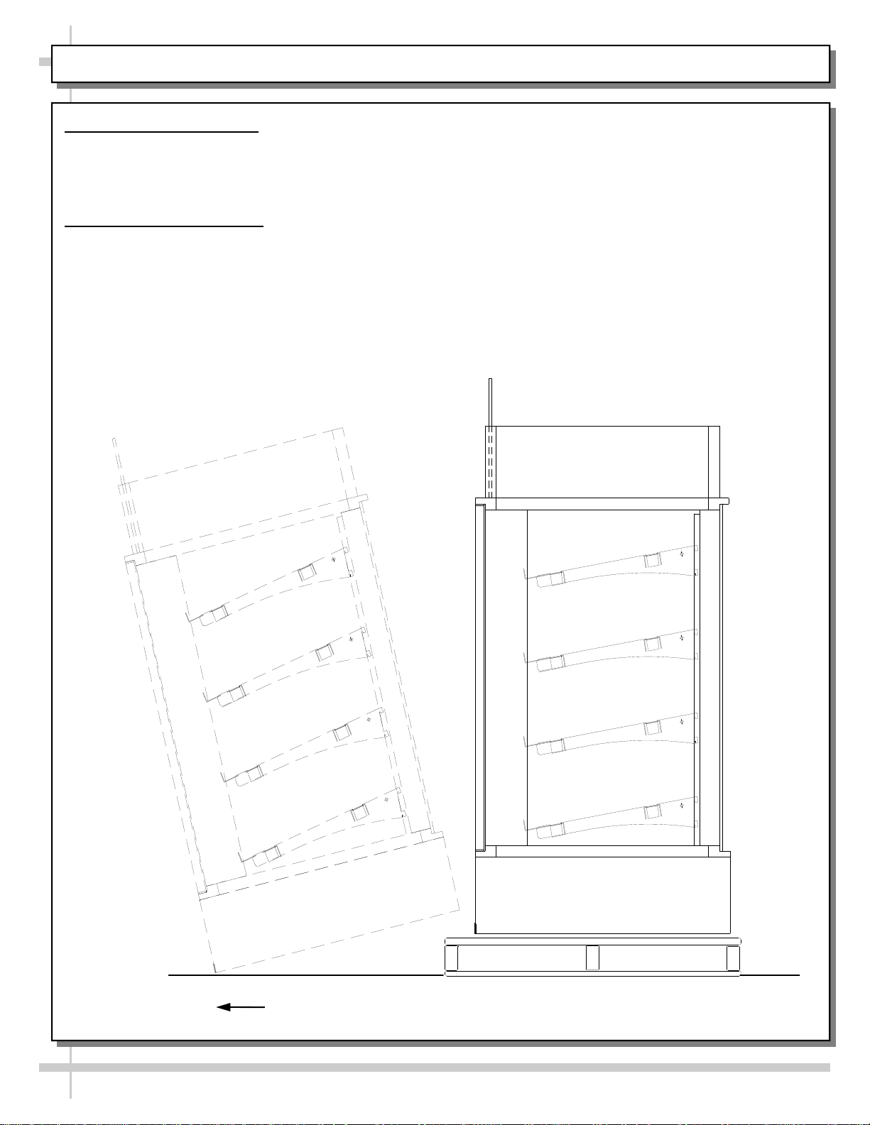
1. Remove Unit From Skid
Position the unit near a suitable electrical outlet.
Caution: Case must always remain supported or center of gravity will allow case to fall.
Slide unit to rear of skid and tip backward off skid.
2. Position and Level Units
For your safety, equipment is furnished with a properly grounded cord connector. Do not attempt to
defeat the grounded connector.
Lift unit with suitable prying bar and blocking. Use care to lift in manner to minimize damage to case.
Rotate leveler to obtain proper height to stabilize and level the unit.
Carefully Slide Unit
Out From Skid
4
Page 5
START-UP AND OPERATION
For your safety, equipment is furnished with a properly
grounded cord connector. Do not attempt to defeat
the grounded connector.
1. Set-up Counter Top Unit
Remove case from skid and place on counter in the
position at which the case will reside.
Note: The following steps must be completed before
this display case may be put in service.
1. After case is in position, apply a steady bead of
silicone around the base and counter top.
2. Allow 24 hours for the silicone to dry before using
the case.
Electrical 120V stub up connections are provided in
the light switch box.
2. Merchandiser Start-Up
Do not use an extension cord with this appliance.
Do not operate this equipment with a damaged cord,
plug or outlet.
Insure the power switch is off.
Plug cord into a certified 120V electrical outlet with
ground.
3. Fluorescent Lights Only
Turn lights on.
On the counter top unit, the light switch is located
behind the tissue box.
On floor models without a storage door the switch
is located at the front base of the unit under the
front panel on the left hand side.
On floor models with a storage door, the light
switch is located inside the base storage area
on the left hand side.
Lights should come on at the same time. First time
lighting may require short warm-up period for bulbs.
Slightly dim or a flickering of new bulbs is normal.
4. LED Lights Only
Lights will come on when case is plugged in.
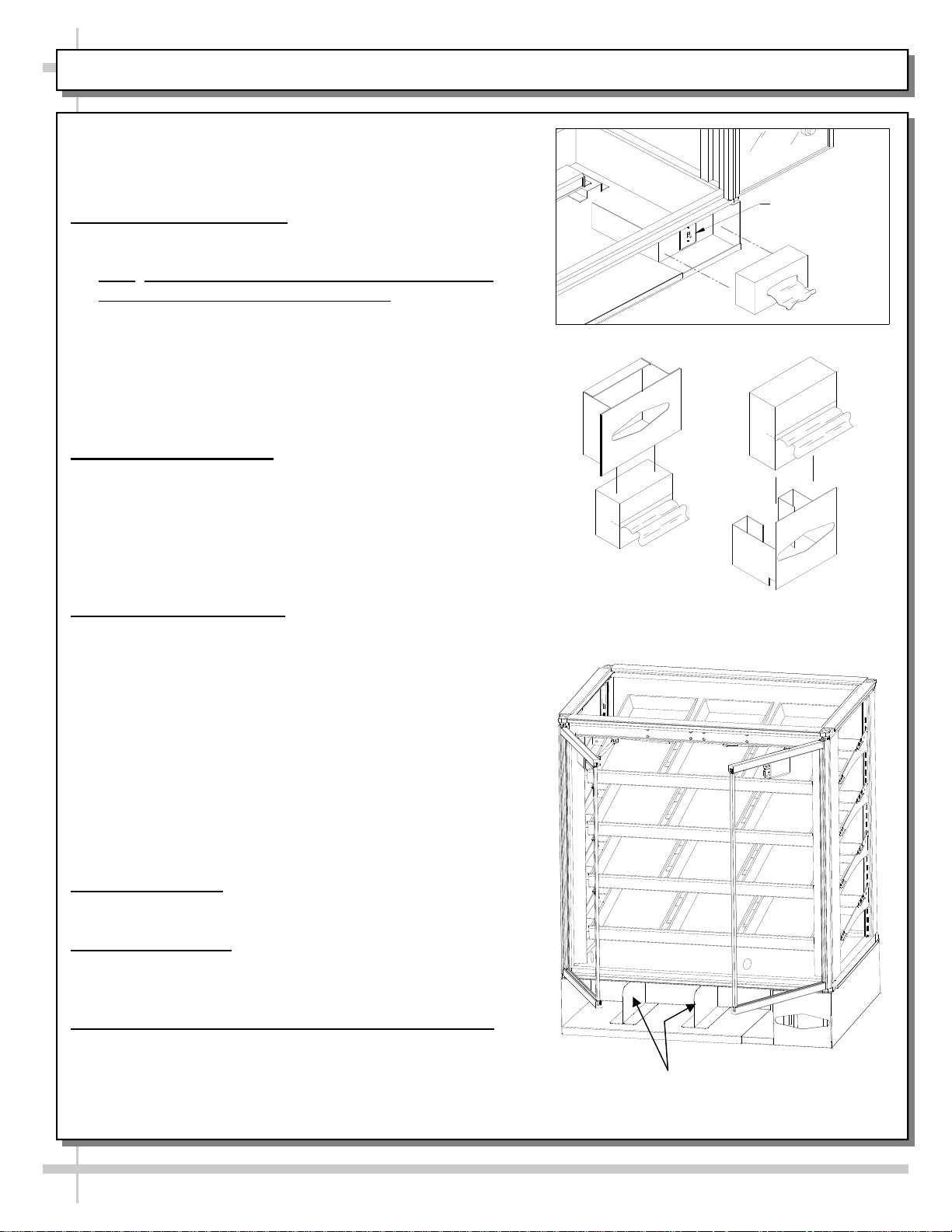
5. Tissue Dispenser
Remove tissue dispenser.
Place a tissue box into the dispenser as shown.
6. Adjustable Front Storage Area Dividers (Optional)
Dividers are held in place with magnetic tape strips.
Dividers may be adjusted to reflect varying widths.
Dividers may be entirely removed from case.
Light Switch
—— Tissue Dispensers ——
Adjustable Front Storage Dividers
(Retained With Magnetic Tape)
5
Page 6

MAINTENANCE FUNDAMENTALS: SHELF ASSEMBLY REMOVAL / DECKING REMOVAL
1. Shelf Assembly Removal
Shelves can be removed for repositioning,
removal (for individual merchandising
requirements) and cleaning.
Slide the front shelf support back rotate up and
lift straight up to separate from brackets.
Slide the rear shelf support back rotate up and
lift straight up to separate from brackets.
Bracket Retainer [Typical]
Remove brackets. Note: It may be necessary to
remove the nylon shipping bracket retainers.
Pliers will be required to accomplish this task.
2. Decking Removal
Remove lower shelf assembly.
Remove interior deck by pushing up from
underneath in the bag storage area.
See illustration at lower right.
Front Shelf Support
6
Rear Shelf Support
Shelf Bracket
Page 7

MAINTENANCE FUNDAMENTALS: STANDARD DOOR MECHANISM / RYOBI DOOR MECHANISM
1. Door “Hold Open” Feature
To reposition the shelving or restock the shelves, it is
first helpful to use the door ‘hold open” feature.
Open the door all the way (See light fixture).
Caution damage will result if pin is not
lowered before attempting to close the doors.
Inside the unit, at the top of each door hinge, is
the pin slide cover.
Slide the pin cover up until the pin extends
approximately 1/2 inch above the door hinge.
Release the door assembly allowing the pin to rest
on the outer door frame.
To close, fully open the door and retract the pin into
the hinge and allow the door to close.
2. Ryobi Door Closing Mechanism (Optional)
Certain models (such as CDR4817) use the Ryobi
door closing mechanism.
When opened approximately 90°, door ‘catches’
and stays open.
When pressure is applied to close door, ‘catch’
PIN EXTENSION
releases and door closes normally.
Ryobi Pivot
Door
Bracket
Ryobi Outer
Arm
Ryobi Inner
Arm
Ryobi Door
Closing
Mechanism
7
Page 8

LIGHT FIXTURES - FLUORESCENT [SEE NEXT PAGE FOR LED LIGHT FIXTURES]
1. Light Fixtures
Light fixtures are located on the sides of each door
assembly, both sides (just inside the doors).
Open the door all the way.
Access lamp by removing the lamp cover/diffuser.
Applying gentle squeezing pressure to lamp
cover and rotating will release the cover.
Removal of lamp:
Press bulb down until top contacts are clear of the
upper socket.
Tilt top of bulb away from the upper socket and lift
bulb out.
Replace bulb by performing this operation in
reverse order.
2. Light Ballast Access
Remove electrical power from the unit.
Engage door “hold open” mechanism.
Remove shelving.
Remove interior deck by pushing up from
underneath in the bag storage area.
Light Assemblies
(Inside Edge - Both Sides)
Ballast
Bulb
Light Assembly
Bulb Cover
Lower Socket
with Spring
8
Page 9

LIGHT FIXTURES - LED [SEE PREVIOUS PAGE FOR FLUORESCENT LIGHT FIXTURES]
1. Light Fixtures
Light fixtures are located on the sides of each
door assembly, both sides (just inside doors).
See illustrations at right.
2. LED Light Fixture Removal
LED Light
Assemblies
(Inside
Edge
Both Sides)
Removal of lamp:
This case is provided with LED lights which
will rarely require change-out.
Contact Structural Concepts’ Technical
Service Department for replacement parts
Decking
(see the Technical Service section of
operating manual).
Replacement of lamp:
To replace LED Light Fixture, disconnect the
existing LED light from its brackets and
self-adhesive tape. Replace.
Note: LED Light and Plug must be connected
in a specific manner or they will not work.
Flat edge of plug must connect to flat edge of
LED light. See illustration below.
3. LED Power Supply Access
Disconnect electrical power from unit.
Engage door “hold open” mechanism.
Remove shelving.
Remove interior deck by pushing up from
underneath in bag storage area.
LED’s
Oval
LED
Power
Supply
Box
Plug’s Oval
Form
View of case with decking removed to access
9
Page 10

SERIAL LABEL LOCATION & INFORMATION LISTED / TECH INFO & SERVICE
Serial Label Location & Information Listed / Technical Information & Service
Serial labels are located near the electrical access on your case.
Serial labels contain electrical, temperature & refrigeration information, as well as regulatory
standards to which the case conforms.
For additional technical information and service, see the TECHNICAL SERVICE page in this
manual for instructions on contacting Structural Concepts’ Technical Service Department.
See images below for samples of both refrigerated and non-refrigerated serial labels.
Y
NL
O
SA
PLE
M
----- Sample Serial Label For Non-Refrigerated Case -----
10
Page 11

TROUBLESHOOTING / CLEANING SCHEDULE
Troubleshooting
Issue Resolution
Case Lights Not Working
System is not Operating
Check bulbs for proper installation and connection.
Check for burned out bulbs.
Confirm the utility power is on.
Check the circuit breaker box for tripped circuits.
Cleaning Schedule
Cleaning Daily Weekly Monthly Task
Clean Case Exterior X
Clean Case Interior X
Clean all case exterior surfaces with a household or
commercial glass cleaner and a soft cloth.
Clean the interior case deck and shelving surfaces
with a warm water and mild soap solution.
11
Page 12

ILLUSTRATED PARTS BREAKDOWN (STANDARD CASE ONLY)
1
8
7
6
2
3
Note: Depending Upon Features
And Options Chosen, Above
Illustration May Not Exactly Reflect
Your Particular Case.
4
5
12
Page 13

ILLUSTRATED PARTS BREAKDOWN
13
9
12
10
11
Note: Depending Upon Features
And Options Chosen, Above
Illustration May Not Exactly Reflect
Your Particular Case.
13
Page 14

PARTS LIST
1 Sign Upright Tube 11 Light Ballast
2 Acrylic Sign Side 12 Light Assembly
3 Shelf Assembly 13 Deck
4 Tissue Holder 14 Shelf Support Front
5 Front Panel or Storage Door 15 Shelf Support Rear
6 Acrylic End Glass 16 Shelf Bracket
7 Top Glass 17 Bulb
8 Acrylic Sign 18 Light Socket
9 Door Assembly 19 Bulb Cover
10 Single Pole Switch
Shelf Assembly
15 14
16
Light Assembly
17
18
Note: Depending Upon Features And
Options Chosen, Above
Illustrations May Not Exactly Reflect
Your Particular Case.
14
14 14
19
Page 15

SCC TECHNICAL SERVICE CONTACT INFORMATION & WARRANTY INFORMATION
STRUCTURAL CONCEPTS CORPORATION TECHNICAL SERVICE
PHONE NUMBER: 1.800.433.9489 or For Your Master Service Agent See
WWW.STRUCTURALCONCEPTS.COM/Contact/Master_Service_Agents.asp
LIMITED WARRANTY
All sales by Structural Concepts Corporation (SCC) are subject to the following limited warranty. “Goods” refers to the product or products being sold by SCC.
Warranty Scope: Warranty is for equipment sold in the United States, Canada, Mexico and Puerto Rico. Equipment sold elsewhere may carry modified warranty.
Warranty; Remedies; Limitations. SCC warrants that if any Goods are found by an authorized representative of SCC not to be of good material or workmanship within one
year of the date of shipments SCC will, at its option after inspection by an authorized representative, replace any defective Good or pay the reasonable cost of replacement for
any such defective Goods, provided that written notice of the defect is given to SCC within 30 days of the appearance of such defect. If notice is not given within such period, any
claim for breach of warranty shall be conclusively deemed to have been waived and SCC shall not be liable under this warranty. If SCC is unable to repair or replace the defective
Goods, SCC shall issue a credit to the Purchaser for all or part of the purchase price, as SCC shall determine. The replacement or payment in the manner described above shall
be the sole and exclusive remedy of Purchaser for a breach of this warranty. If any Goods are defective or fail to conform to this warranty, SCC will furnish instructions for their
disposition. No Goods shall be returned to SCC without its prior consent.
SCC’s liability for any defect in the Goods shall not exceed the purchase price of the Goods. SCC SHALL HAVE NO LIABILITY TO PURCHASE FOR CONSEQUENTIAL
DAMAGES OF ANY KIND WHATSOEVER, INCLUDING, BUT NOT LIMITED TO, PERSONAL INJURY, PROPERTY DAMAGE, LOST PROFITS, OR OTHER ECONOMIC
INJURY DUE TO ANY DEFECT IN THE GOODS OR ANY BREACH OF SCC, SCC SHALL NOT BE LIABLE TO THE PURCHASER IN TORT FOR ANY NEGLIGENT DESIGN
OR MANUFACTURE OF THE GOODS, OR FOR THE OMISSION OF ANY WARNING THEREFROM.
SCC shall have no obligation or liability under this warranty for claims arising from any other party’s (including Purchaser’s) negligence or misuse of the Goods or environmental
conditions. This warranty does not apply to any claim or damage arising for or cause by improper storage, handling, installation, maintenance, or from fire, flood, accidents,
structural defects, building settlement or movement, acts of God, or other causes beyond SCC’s control.
Except as expressly stated herein, SCC makes no warranty, express, implied, statutory or otherwise as to any parts or goods not manufactured by SCC. SCC shall warrant such
parts or Goods only (I) against such defects, (II) for such periods of time, and (III) with such remedies, as are expressly warranted by the manufacturer of such parts of Goods.
Notwithstanding the foregoing, any warranty with respect to such parts of Goods and any remedies available as a result of a breach thereof shall be subject to all of the
procedures, limitations, and exclusions set forth herein.
THE WARRANTIES HEREIN ARE IN LIEU OF ALL WARRANTIES, EXPRESS, IMPLIED, STATUTORY, OR OTHERWISE. IN PARTICULAR, SCC MAKES NO WARRANTY
OF MERCHANTABILITY OR FITNESS FOR A PARTICULAR PURPOSE.
No representative, agent or dealer of SCC has authority to modify, expand, or extend this Warranty, to waive any of the limitations or exclusions, or to make any different or
additional warranties with respect to Goods.
Period of Limitations. No claim, suit or other proceeding may be brought by Purchaser for any breach of the foregoing warranty or this Agreement by SCC or in any way arising
out of this Agreement or relating to the Goods after one year from the date of the breach. In the interpretation of this limitation on action for a breach by SCC, it is expressly
agreed that there are no warranties of future performance of the goods that would extend that period of limitation herein contained for bringing an action.
Indemnifications. Purchaser agrees to indemnify, hold harmless, and defend SCC if so requested, from any and all liabilities, as defined herein, suffered, or incurred by SCC as
a result of, or in connection with, any act, omission, or use of the Goods by Purchaser, its employees or customers, or any breach of this Agreement by Purchaser. Liabilities
shall include all costs, claims, damages, judgments, and expenses (including reasonable attorney fees and costs).
Remedies of SCC. SCC’s rights and remedies shall be cumulative and may be exercised from time to time. In a proceeding or action relating to the breach of this Agreement by
Purchaser, Purchaser shall reimburse SCC for reasonable costs and attorney’s fees incurred by SCC. No waiver by SCC of any breach of Purchaser shall be effective unless in
writing nor operate as a waiver of any other breach of the same term thereafter. SCC shall not lose any right because it has not exercised it in the past.
Applicable Law. This Agreement is made in Michigan and shall be governed by and interpreted according to Michigan law. Any lawsuit arising out of this Agreement or the Goods
may be handled by a federal or state court whose district includes Muskegon County, Michigan, and Purchaser consents that such court shall have personal jurisdiction over
Purchaser.
Miscellaneous. If any provision of this Agreement is found to be invalid or unenforceable under any law, the provision shall be ineffective to that extent and for the duration of
the illegality, but the remaining provisions shall be unaffected. Purchaser shall not assign any of its rights nor delegate any of this obligations under this Agreement without prior
written of SCC. This Agreement shall be binding upon and inure to the benefit of SCC and Purchaser and each of their legal representatives, successors and assigns.
SCC warrants its products to be free of defects in materials and workmanship under normal use and service for a period of one (1) year from the date of delivery.
This warranty is extended only to the original purchaser for use of the Goods. It does not cover normal wear parts such as plastic tongs, tong holders, tong cables, bag holders,
or acrylic dividers.
General Conditions. All service labor and/or parts charges are subject to approval by SCC. Contact the Customer Service Department in writing or call 231-798-8888.
All claims must contain the following information: (1) model & serial code number of equipment; (2) the date and place of installation; (3) the name and address of the agency
which performed the installation; (4) the date of the equipment failure; and (5) a complete description of the equipment failure and all circumstances relating to that failure.
Once the claim has been determined to be a true warranty claim by SCC’s Customer Service Department, the following procedure will be taken: (1) replacement parts will be sent
at no charge from SCC on a freight prepaid basis; (2) reimbursement for service labor will be paid if the following conditions have been met - (a) prior approval of service agency
was awarded from the Customer Service Department; and (b) an itemized statement of all labor charges incurred is received by the Customer Service Department. The cost of
the service labor reimbursement will be based on straight time rates and reasonable time for the repair of the defect.
If problems occur with any compressor, notify SCC’s Customer Service Department immediately. Any attempt to repair or alter the unit without prior consent from the Customer
Service Department will render any warranty claim null and void. This warranty and protection plan does not apply to any condensing unit or any part thereof which has been
subject to accident, negligence, misuse, or abuse, or which has not been operated in accordance with the manufacturer’s recommendations or if the serial number of the unit has
been altered, defaced, or removed.
Limit of Liability. The limit of liability of SCC toward the exchange cost of the original condensing unit, F.O.B. SCC, Norton Shores, MI, of each motor-compressor assembly
replaced during the warranty shall not exceed manufacturer's current established wholesaler’s exchange price and in no case shall the labor of removing or replacing the
motor-compressor or parts thereof be the responsibility of SCC.
15
 Loading...