

Page 1

STIHL E 140, 160, 180
STIH)
2003-01
Page 2

1. Introduction 2
2. Specifications 3
2.1 Motor 3
2.2 Gear Drive 3
2.3 Cutting Attachment 3
2.4 Tightening Torques 4
3. Wiring Diagram/
Description 5
4. Removing and
Installing Electrical
Components 6
4.1 Power Cable 6
4.2 Trigger Switch 8
4.3 Capacitor (230 V only) 8
4.4 Overload Circuit Breaker 8
(E 160, E 180 C only)
4.5 Chain Brake Switch 9
5. Motor 10
5.1 Carbon Brushes 10
5.2 Rotor 11
5.3 Rotor Bearing 13
5.4 Fanwheel 13
5.5 Stator 14
6. Chain Drive 15
6.1 Chain Sprocket 16
6.2 Ring Gear and Pinion 16
6.3 Gear Housing 16
7. Chain Tensioner 17
7.1 Front Chain Tensioner 17
7.2 Side Chain Tensioner 17
7.3 Quick Chain Tensioner 18
8. Chain Brake 18
8.1 Removal 18
8.2 Installation 20
9. Chain Lubrication 21
9.1 Oil Tank 21
9.2 Oil Strainer 21
9.3 Oil Pump 21
10. Special Servicing Tools
and Aids 23
10.1 Special Servicing Tools 23
10.2 Servicing Aids 23
©1998,AndreasStihlAG&Co.,Waiblingen
CONTENTS
E140,E160,E180 1
Page 3
This service manual contains
detailed descriptions of all servicing procedures for STIHL model
E140,E160andE180Celectric
chainsaws and can thus be used
as a basis for professional overhauls and repairs on all versions
of these machines.
As the constructional features of
these electric saws are almost
identical, the servicing procedures
generally apply to all three
models. Differences are described
in detail and special reference is
made to the model concerned in
each case.
Caution: When carrying out repairs to electric saws it is essential
to observe all relevant national safety regulations and ordinances.
We recommend that you make
use of the exploded views in the
illustrated parts lists while carrying
out repair work. Most of the illustrations show the installed positions
of the individual components and
assemblies.
Refer to the latest edition of the
parts list for the part numbers of
any spare parts you may require.
Microfilmed parts lists are always
more up to date than printed lists.
Afaultonthepowertoolmayhave
several causes. Consult the
troubleshooting charts for all
assemblies in the "Standard
Repairs, Troubleshooting" handbook and the troubleshooting
charts immediately after the specifications in this manual.
Refer to the "Technical Information" bulletins for engineering changes which have been introduced
since publication of this service
manual. Technical information
bulletins also supplement the parts
list until a revised edition is
issued.
The special servicing tools mentioned in the descriptions are
listed in the last chapter of this manual.
Use the part numbers to identify
the tools in the "STIHL Special
Tools" manual.
The manual lists all special servicing tools currently available
from STIHL.
Symbols are included in the text
and pictures for greater clarity.
The meanings are as follows:
In the descriptions:
•
=Actiontobetakenas
shown in the illustration
(above the text)
-= Actiontobetakenthat
is not shown in the
illustration
(above the text)
In the illustrations:
=Pointer
=Directionofmovement
Servicing instructions and all
technical information bulletins describing engineering changes are
intended exclusively for the use of
STIHL servicing dealers. They
must not be passed to third parties.
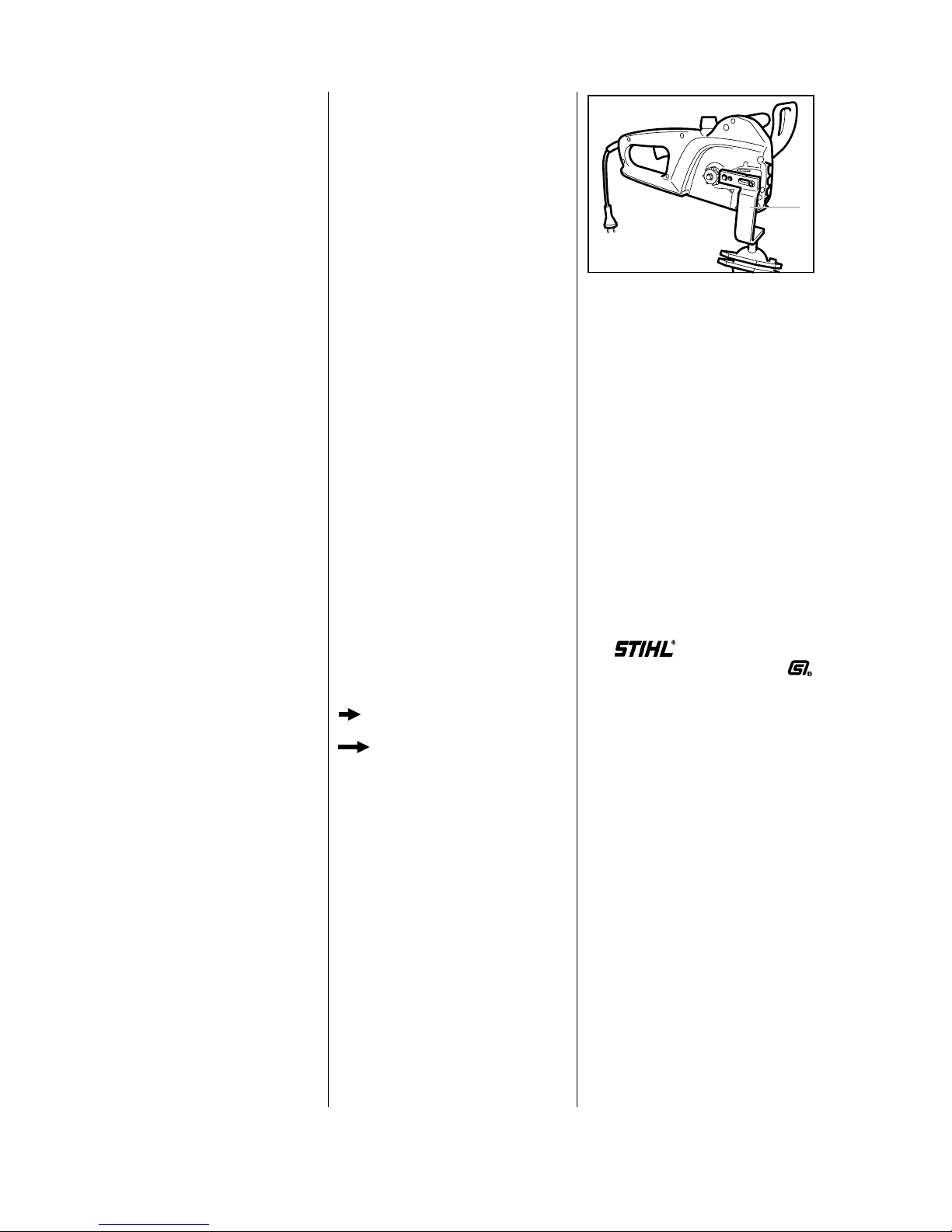
Servicing and repairs are made
considerably easier if the electric
saw is mounted to the assembly
stand (1) 5910 890 3100.
This enables the saw to be swivelled to the best position for the ongoing repair and leaves both
hands free.
It is secured with the sprocket cover nut (after removing sprocket
cover). On the E 180 C, remove
the quick chain tensioner and the
secure saw to stand with an M8
nut.
Always use original STIHL
replacement parts.
They can be identified by the
STIHL part number,
the logo
and the STIHL parts symbol
The symbol may appear alone on
small parts.
1. INTRODUCTION
100RA001
1
VA
2 E140,E160,E180
Page 4

2.1 Motor E 140 E 160 E 180 C
Type: Universal motor
Rating (kW): 1.4 1.6 1.8
Rated voltage (V): 120; 230 230 120; 230
Frequency (Hz): 60 50 50 60 50
Rated current (A): 11.7 6.4 7.3 15,0 8.2
Fuse (slow-blowing) (A): 15 16 16 15 16
Overload protection: Thermal overload circuit breaker
Type of enclosure: IP 20
Class of protection: II
Coasting brake: Mechanical
2.2 Gear Drive
Type: Straight-toothed ring gear with pinion, single-stage
Output speed with
bar and chain,
off load (idle): 5900 rpm
1)
6300 rpm 6900 rpm
3)
at rated load: 5000 rpm
2)
5400 rpm 5400 rpm
4)
Lubrication: STIHL multipurpose grease
2.3 Cutting Attachment
Chain sprocket: 7-tooth 3/8" Picco
spur sprocket
Chain lubrication: Fully automatic, speed-controlled reciprocating oil pump
Oil tank capacity: 0.20 l (0.4 US pt)
1)
120 V : 6100 rpm
2)
120 V : 4900 rpm
3)
120 V : 6800 rpm
4)
120 V : 5000 rpm
2. SPECIFICATIONS
3
Page 5

Plastoform screws are used in polymer components. These screws form a permanent thread when
they are installed for the first time. They can be removed and installed as often as necessary without
detrimentally affecting the strength of the screwed assembly, providing the specified tightening torque
is observed.
For this reason always use a torque wrench.
Fastener Thread For component Torque Remarks
size Nm lbf.ft
Self-tapping screw IS-B6.3x32 LH hand guard/motor housing 4.5 3.3
Slotted nut M5 L Drive pinion/rotor shaft 8.0 5.9 1)
Plastoform screw IS-P3x10 Cover plate/sprocket cover 1.0 0.75
Plastoform screw IS-P4.5x25 Commutator cover/motor housing 3.0 2.2
Plastoform screw IS-P4.5x45 Stator/motor housing (1200 W) 3.0 3.0
Plastoform screw IS-P4.5x55 Stator/motor housing (1400, 1600 W) 3.0 3.0
Plastoform screw IS-P4x19 Oil pump/gear housing 2.5 1.8
Plastoform screw IS-P4x19 Handle housing/motor housing 2.0 1.5
Plastoform screw IS-P4x19 Cable clamp/motor housing 1.5 1.1
Plastoform screw IS-P5x20 Spiked bumper/handle housing 4.0 3.0
Plastoform screw IS-P5x20 Gear housing/motor housing 3.0 2.2
Spline screw IS-M6x25 Brake band/gear housing 6.0 4.4
Use the following procedure to fit a ’P’ screw in an existing thread:
–PlacethePscrewintheholeandrotateitcounterclockwiseuntilitdropsdownslightly.
–Tightenthescrewclockwisetothespecifiedtorque.
This procedure ensures that the screw engages properly in the existing thread and does not form a new thread.
1) Secure slotted nut with Loctite 242.
Note: Screws/nuts secured with adhesive are easier to release if they are heated beforehand with a hot air blower (hairdryer).
Be careful with polymer components!
Power screwdriver speed settings for polymer: Plastoform screws max. 600 rpm,
DG screws max. 500 rpm
2.4 Tightening Torques
4
Page 6
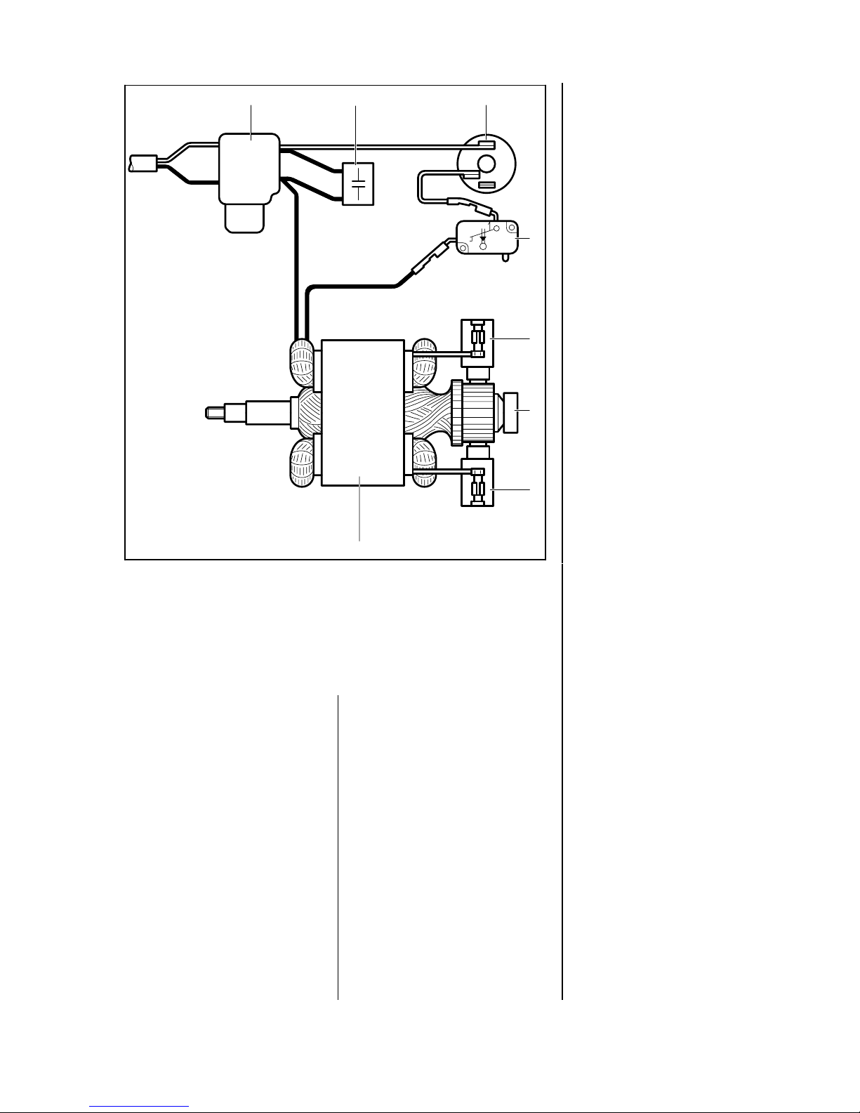
The trigger switch (1) is equipped
with a mechanical starting lockout
(interlock button) which helps prevent unintentional switch-on.
The saws feature a thermal overload circuit breaker (3) to protect
the electric motor from mechanical
overload.
This overload circuit breaker interrupts the power supply to the saw
if the operator continues cutting for
an extended period with an overtensioned chain, uses excessive
feed force, "lugs down" the motor
speed or if the chain is suddenly
stopped by being pinched in the
cut.
Before restarting the saw and continuing work it is necessary to pull
the guide bar out of the cut and
wait for a short period until the
overload circuit breaker has cooled down. The overload circuit
breaker can then be reset by pressing in the button as far as
the stop.
This is not a fault. The remedy in
such a case is to work with less
feed effort. Under no circumstances should the overload circuit
breaker be bypassed, even if the
owner explicitly requests such a
modification.
Chain brake
The brake lever is unlatched when
the "Quickstop" chain brake is
activated, either manually or by
inertia. The power supply is interrupted immediately by the chain
brake switch (4) and the spring-loaded brake band is clamped around
the brake drum at the same instant.
This causes the saw chain to be
brought to a standstill and locked
in position. The chain brake is
disengaged by moving the hand
guard toward the front handle.
Coasting brake
The coasting brake supplements
the chain braking system. It brings
the rotating chain to a standstill
when the operator releases the
trigger switch.
In the idle condition, an additional
spring clamps the brake band around the brake drum.
When the trigger switch is squeezed, the brake band is first disengaged from the brake drum via a
linkage. Only then does the switch
close and start the motor.
3. WIRING DIAGRAM/DESCRIPTION
100RA002
2
3
2
1
2
1
1
2
K
1 2 3
4
5
6
5
7
VA
1Triggerswitch
2Capacitor(230Vonly)
3Overloadcircuitbreaker(E160,E180Conly)
4Chainbrakeswitch
5Brushholderwithcarbonbrush
6Rotor
7Stator
5
Page 7
Important: The electrical safety of
the saws should be checked after
every repair by performingahighvoltage insulation test. Tests of
this kind may only be carried out
by electricians or specially trained
personnel.
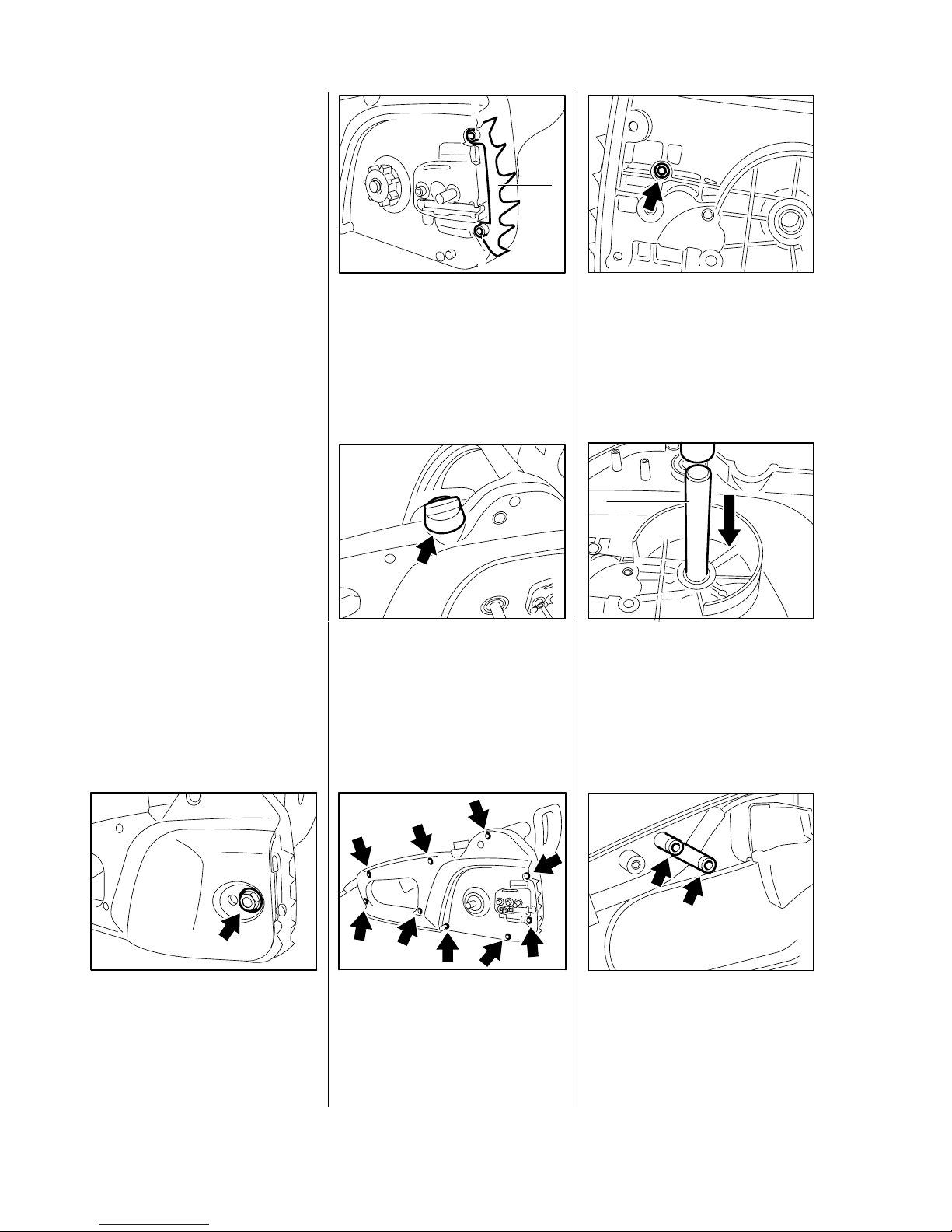
Always unplug the machine from
the mains supply.
- Remove the quick chain
tensioner, if fitted - see 7.3.
•
Unscrew nut.
- Remove the chain sprocket
cover.
Models with quick chain
tensioner
•
Take out screws (1).
•
Remove the spiked bumper (2).
All models
- Remove the chain sprocket -
see 6.1.
•
Unscrew oil filler cap and remove together with cap retainer.
•
Take out the screws.
- Remove the handle housing.
•
Take out the O-ring.
- Placeasocket (e.g. 19mm)
under the handle housing so that
it supports the bearing bush from
outside.
•
Use drift (1) 1111 893 4700 to
press needle sleeve out of
bearing bush.
•
Take out the screws.
- Remove the strain relief cable
clamp.
100RA005
VA
100RA008
1
VA
100RA004
2
1
1
VA
100RA003
VA
4. Removing and Installing Electrical Components
4.1 Connecting Cord
100RA007
VA
100RA006
VA
100RA009
VA
6
Page 8
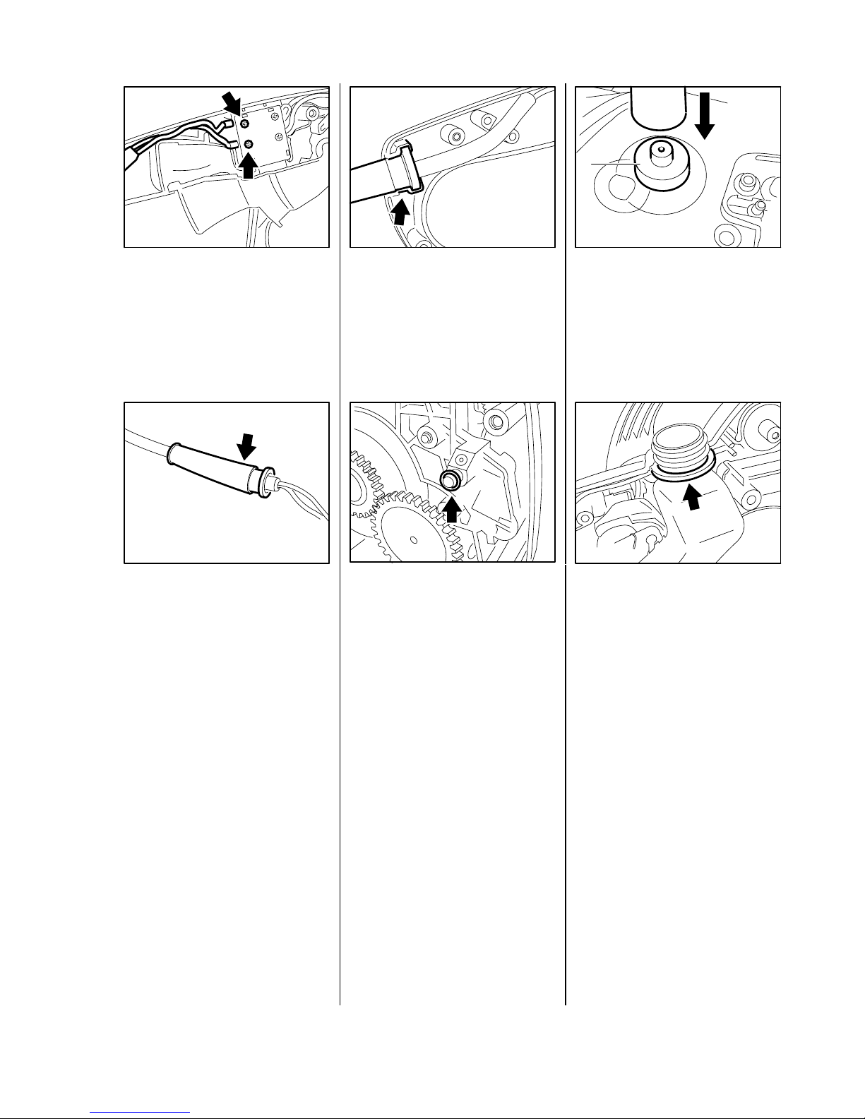
•
Slacken off the screws.
- Pull the wires out of the switch.
•
Pull cable protector off the old
connecting cord.
Installation is a reversal of the
removal sequence.
- Slip the cable protector, thin end
first, over the new connecting
cord.
•
Check that cable protector is
correctly seated.
- Fit the strain relief clamp
and tighten screws to 1.5 Nm
(1.1 lbf.ft).
•
Fit a new O-ring on gear housing
pivot pin.
- Place a socket (e.g. 19mm)
under the handle housing so that
it supports the bearing bush from
inside.
•
Use press arbor (1) 4116 893
7205 to install needle sleeve in
the bearing bush.
•
Check condition of sealing ring
on oil tank and fit a new one if
necessary - see 9.1.
- Tighten the handle housing
mounting screws to 2.0 Nm
(1.5 lbf.ft).
100RA014
1
VA
100RA011
VA
100RA012
VA
100RA015
VA
100RA010
VA
100RA013
VA
7
Page 9

- Remove the handle housing -
see 4.1.
•
Release the screws.
•
Disconnect wires (1) of
connecting cord.
•
Ease the trigger switch slightly
away from the motor housing
and disconnect the wires (2)
from the other side of the switch.
•
Remove the trigger switch (3).
Install in the reverse sequence.
Important: The wires must be reconnected to the same terminals,
see also 3.
- Remove the trigger switch -
see 4.2.
•
Cut the wire end ferrules off the
wires.
•
Pull the capacitor out of the
motor housing.
Install in the reverse sequence.
- Use wire end ferrules to connect
wires from overload circuit breaker and stator to the capacitor’s
wires.
The overload circuit breaker
interrupts the power supply to
protect the motor in the event of
mechanical overload (e.g. cutting
for extended period with excessive
feed force, suddenly stopping the
chain by pinching it in the cut).
Warning: The overload circuit
breaker and chain brake switch
must never be bypassed.
- Remove the oil tank - see 9.1.
•
Release the screw (1).
•
Disconnect the wires from the
switch.
•
Cut wire end ferrule (2) off the
wires.
100RA019
VA
100RA016
VA
100RA017
1
2
3
VA
100RA020
1
2
VA
100RA018
VA
4.2 Trigger Switch 4.3 Capacitor 4.4 Overload Circuit Breaker
(230 V only) (E 160, E 180 C)
8
Page 10

•
Pull off the terminal.
•
Pull overload circuit breaker out
of the motor housing.
Install in the reverse sequence.
•
Use new wire end ferrule to join
the wire from the switch and
capacitor and push into the retainers in the motor housing.
- Remove the handle housing -
see 4.1.
•
Remove the wires from the
brake switch terminals.
•
Lift snap hook (1) a little and
then pull out the chain brake
switch (2).
Install in the reverse sequence.
100RA022
VA
100RA025
VA
1
2
100RA021
VA
100RA023
VA
100RA024
VA
4.5 Chain Brake Switch
9
Page 11

•
Take out the screws.
- Remove the commutator cover.
•
Pull the wire off the connector
tag.
Pull the brush holder forwards and
take it away.
Note: The friction generated by
the carbon brushes causes the
commutator surface to wear gradually and eventually leaves serious scores. These scores cause
increased sparking between the
carbon brushes and commutator.
If the carbon brushes can be reused, do not change their installed
positions.
•
Inspect commutator before fitting
the carbon brushes and replace
the rotor if necessary - see 5.2.
- Check that the carbon brush moves freely in the brush holder.
•
Fit the brush holder so that the
top and bottom lugs slide into the
slots in the housing.
- Push wire onto connector tag.
- Refit commutator cover and
tighten screws to 3.0 Nm
(2.2 lbf.ft).
100RA027
VA
100RA031
VA
100RA028
VA
VA
100RA030
100RA029
VA
5. MOTOR
5.1 Carbon Brushes
10
Page 12

- Remove carbon brushes -
see 5.1.
- Remove oil tank - see 9.1.
Remove the ring gear and spur
gear - see 6.2.
•
Take out the screw (1).
•
Pull off the hand guard (2).
•
Pull wires off connector tags on
chain brake switch.
•
Remove screws from gear
housing.
•
Remove the gear housing and
pull the rotor out of the stator at
the same time.
•
Disconnect the tension springs.
- Useahot air blower to heat the
pinion mounting nut.
•
Hold pinion steady and unscrew
slotted mounting nut in direction
of arrow (left-hand thread).
•
Pry the pinion off the rotor shaft.
•
Pull the rotor out of the ball
bearing.
100RA032
1
2
VA
100RA034
VA
100RA033
VA
100RA024
VA
VA
100RA035
100RA036
VA
100RA037
VA
5.2 Rotor
VA
100RA038
11
Page 13

•
Examine brake drum (1) and fanwheel (2), replace if necessary -
see 5.4.
Note: If brake drum has to be replaced, also check the brake band
- see 8.1
- If brake drum is still serviceable,
clean and roughen its friction
face with emery paper or cloth
(grain size approx. 120µm).
•
Inspect the rotor core assembly
(1) for damage and replace the
rotor if necessary. The fanwheel
and ball bearing have to be removed for this purpose - see 5.4
and 5.3.
•
Inspect the commutator (2).
Note: In case of minor running
marks, dress the commutator
with emery cloth. If running
marks are severe, fit new rotor.
•
Examine ball bearing (3) and
replace if necessary - see 5.3.
Install in the reverse sequence.
- Clean thread of slotted nut and
rotor stub with standard commercial, solvent-based degreasant
containing no chlorinated or
halogenated hydrocarbons -
see 10.2.
- Coat thread of slotted nut with
Loctite, see 10.2, and screw
slotted nut into pinion.
•
Hold pinion steady and tighten
down slotted nut to 8.0 Nm
(5.9 lbf.ft).
•
Attach smaller spring (1) to
brake lever (2).
•
Use assembly tube (2) 1117 890
0900 to hook larger spring (1) to
pivot pin.
- Torque down gear housing
screws to 3.0 Nm (2.2 lbf.ft) and
screw on hand guard to 4.5 Nm
(3.3 lbf.ft).
VA
2
1
100RA040
VA
100RA039
1 2
VA
100RA041
1
2
3
100RA043
VA
1 2
VA
100RA042
12
Page 14

- Remove the rotor - see 5.2.
•
Pull the ball bearing off the rotor
shaft.
•
Remove the nylon washer and
inspect it. Refit it so that its flat
side is against the commutator.
- Heat ball bearing to approx.
50°C (120°F) and push it on as
far as stop.
Check ball bearing in gear housing. If ball bearing is faulty, fit a
new gear housing - see 6.3.
- Install the rotor - see 5.2.
- Remove the rotor - see 5.2.
•
Rest fanwheel flange (see arrow)
on two flat steel bars (5x20x130
mm).
- Position flat steel bars with rotor
inapress.
Note: The rotor must hang freely.
•
Useahot air blower to heat the
hub area of the brake drum.
VA
100RA045
VA
100RA044
VA
100RA047
100RA046
VA
100RA048
VA
5.3 Rotor Bearing 5.4 Fanwheel
13
Page 15

•
Hold the rotor and press it out of
the brake drum and fanwheel.
- Clean stub of rotor shaft with
standard commercial, solvent-
-based degreasant containing
no chlorinated or halogenated
hydrocarbons - see 10.2.
•
Push the fanwheel, flange first,
onto the rotor shaft as far as it
will go.
- Coat the flats on the rotor shaft
with Loctite 648 - see 10.2.
•
Fit the brake drum so that the
closed side faces the fanwheel.
- Stand the rotor upright on a
socket (e.g. 19 mm) with the
brake drum at the bottom.
•
Press the rotor down until the
brake drum locates against the
shaft shoulder.
- Install the rotor - see 5.2.
- Remove the rotor - see 5.2.
•
Pull the air baffle out of the
housing.
•
Release screw (1) on switch (2).
•
Pull wires out of switch. Cut the
end ferrule (3) off the end of the
wires.
•
Take out the screws.
- Press stator out of housing.
5.5 Stator
100RA053
VA
100RA055
VA
100RA052
VA
VA
100RA050 100RA049
VA
100RA051
VA
100RA054
231
VA
14
Page 16

- Check insulation of field coils.
Note: Install a new stator if
insulation is damaged.
- Check condition of stator’s inner
running surface. Replace stator if
necessary.
•
Place stator in position. Use
screwdriver (1) 5910 890 2400 to
press stator home as far as stop.
Warning! Make sure wires for
carbon brushes are not pinched
in this process.
- Fit stator mounting screws and
tighten to 3.0 Nm (3.0 lbf.ft).
Installation is now a reversal of the
removal sequence.
- Remove the chain sprocket
cover - see 4.1.
•
Use screwdriver to remove
E-clip (1).
•
Remove the washer (2).
•
Pull the chain sprocket off the
shaft.
•
Remove the washer.
Install in the reverse sequence.
- Remove the handle housing -
see 4.1.
•
Pull the spur gear out of the oil
pump.
•
Remove washer if it is still
sticking to the spur gear.
•
Take thrust washer off the ring
gear shaft.
6. CHAIN DRIVE 6.2 Ring Gear and Pinion
6.1 Chain Sprocket
100RA056
VA
2 1
VA
100RA061
100RA059
VA
100RA058
VA
100RA065
1
VA
100RA057
VA
100RA060
VA
15
Page 17

•
Pull ring gear out of needle
bearing in gear housing.
•
Take the thrust washer off the
ring gear shaft.
•
Check condition of needle bearing in gear housing and replace
if necessary.
- Check condition of needle bearing in handle housing and
replace if necessary - see 4.1.
- Remove ring gear - see 5.2.
•
Only replace pinion (1) and ring
gear (2) as matching set.
Install in the reverse sequence.
- Coat ring gear and washer with
lubricating grease - see 10.2.
•
Fit washer in oil pump if it was
removed from the spur gear.
- Remove the rotor - see 5.2
- Remove the oil pump - see 9.2.
- Remove chain brake - see 8.1.
•
Lift snap hook (1) a little and
then pull out the chain brake
switch (2).
•
Pull the oil strainer off the stub.
Install in the reverse sequence.
1
100RA071
2
VA
100RA063
VA
100RA062
VA
100RA070
VA
6.3 Gear Housing
100RA064
VA
100RA067
1
2
VA
100RA085
VA
16
Page 18

- Remove the chain sprocket
cover - see 4.1.
•
Pull the cover out of the motor
housing.
•
Unscrew the tensioning nut (1)
from the adjusting screw (2).
•
Take the adjusting screw out of
the cover (3).
Install in the reverse sequence.
- Remove the chain sprocket
cover - see 4.1.
•
Take out the complete chain
tensioner.
•
Remove the thrust pad (1).
•
Rotate the spur gear (2) to
unscrew the adjusting screw (3)
fully from the tensioner slide (4).
•
Pull the spur gear (1) out of the
cover (2).
•
Pull off the tensioner slide (1).
•
Take out the adjusting screw (2).
- Inspect the teeth on the spur
gear and adjusting screw,
replace both parts if necessary.
Install in the reverse sequence.
Note: Coat teeth of adjusting
screw and spur gear with
lubricating grease, see 10.2,
before refitting.
7. CHAIN TENSIONER
7.1 Front Chain Tensioner 7.2 Side Chain Tensioner
100RA074
1 4 3 2
VA
100RA076
21
VA
100RA072
VA
100RA073
VA
100RA075
2 1
VA
143RA052
VA
1
2
3
17
Page 19

•
Pull out hinged handle (1) of
wingnut (2).
•
Unscrew the wingnut and
remove the chain sprocket
cover (3).
•
Ease the wingnut out of the
chain sprocket cover.
- Push the wingnut into the chain
sprocket cover until it snaps into
position.
- Remove the gear housing -
see 5.2.
- Remove brake drum if necessary
- see 5.4.
•
Carefully pull the switch lever off
the pivot.
•
Disconnect brake rod from the
pawl.
•
Pry the pawl out of the switch
lever.
•
Take the torsion spring off the
pawl.
Install in the reverse sequence.
•
Check installed position of
torsion spring.
7.3 Quick Chain Tensioner 8. CHAIN BRAKE
8.1 Removal
100RA077
1
2
3
VA
100RA078
VA
100RA086
VA
100RA087
VA
100RA088
VA
100RA089
VA
100RA090
VA
18
Page 20

- Remove the switch lever -
see 8.1.
- Remove the rotor - see 5.2.
•
Unhook brake rod from brake
lever.
•
Detach the springs.
•
Remove the brake band fasten-
ing screw.
•
Pry the brake band out of the
gear housing.
•
Unhook brake band from brake
lever.
- Inspect brake band and fit new
one if:
- there are definite signs of wear
(large areas of inside diameter
and/or parts of outside diameter)
and
- band thickness is less than 0.6
mm (0.025").
Important: The brake band must
must not be thinner at any point.
- If the brake band is still serviceable, clean and roughen its
entire friction surface (inside of
brake band) with emery paper or
cloth (grain size approx. 120 µm).
•
Pry the carrier and articulated
lever off the bearing pin and lift
them away together.
- Pull the articulated lever out off
the carrier.
•
Remove the flat spring.
- Inspect all parts. Always replace
damaged parts.
- Clean housing recess for chain
brake mechanism.
VA
100RA091
VA
100RA092
100RA093
VA
100RA094
VA
100RA095
VA
100RA097
VA
100RA098
VA
19
Page 21

- Coat all sliding aand pivot points
with STIHL multipurpose grease
or, preferably, with molybdenum
grease (e.g. Molykote) - see 10.2.
- Fit the flat spring.
•
Fit articulated lever (1) in
carrier (2) as shown in the
illustration.
•
Slip the carrier (1) over the bearing pin (2) and the bore (3) of
articulated lever (4) over bearing
pin (5).
•
Check that flat spring (1) is
correctly positioned on face (2)
of bearing boss.
•
Attach brake band to brake
lever.
•
Position brake band in slots in
gear housing and press it home.
•
Fit brake band fastening screw
and tighten to 6.0 Nm (4.5 lbf.ft).
•
Attach the springs.
•
Attach brake rod to brake lever.
- Install the rotor - see 5.2.
- Fit the switch lever - see 8.1.
8.2 Installation
100RA099
1 2
VA
100RA100
2
5
1
4 3
VA
100RA101
2
1
VA
100RA095
VA
100RA102
VA
100RA103
VA
VA
100RA092
VA
100RA091
20
Page 22

- Remove the handle housing -
see 4.1.
•
Remove the oil tank and pull it
off the oil strainer at the same
time.
•
Remove the sealing ring from
the oil tank.
•
Take grommet out of the oil tank.
Install in the reverse sequence.
- Remove the oil tank - see 9.1.
•
Pull the oil strainer off the stub.
- Clean the oil strainer, check it for
damage and fit a new one if
necessary.
Install in the reverse sequence.
- Remove the handle housing -
see 4.1.
•
Pull the spur gear out of the oil
pump.
•
Remove washer if it is still
sticking to the spur gear. If not,
take the washer out of the oil
pump.
•
Take out the screws.
9. CHAIN LUBRICATION
9.1 Oil Tank 9.2 Oil Strainer 9.3 Oil Pump
VA
100RA068
100RA003
VA
100RA105
VA
100RA104
VA
100RA059
VA
100RA060
VA
100RA106
VA
21
Page 23

•
Pull oil pump out of housing.
Note: Make sure the pin does not
fall out of the oil pump.
•
Remove the O-rings.
Install in the reverse sequence.
•
If the pin has fallen out of the oil
pump, refit it with lubricating
grease - see 10.2.
-AlwaysusenewO-rings.
-Tightendownoilpumpmounting
screws to 2.5 Nm (1.8 lbf.ft).
•
Fit the washer in the oil pump.
100RA107
VA
100RA108
VA
100RA109
VA
100RA110
VA
22
Page 24

10. Special Servicing Tools and Aids
10.1 Special Servicing Tools
No. Part Name Part No. Application Rem.
1Assemblytube 11178900900 Attachingsprings
2ScrewdriverT20x100 59108902301 ReleasingISscrews 1)
3SplinescrewsocketT20x120 08125422041 TighteningISscrews
4T-handle screwdriver
QI-T27x150 5910 890 2400 Releasing IS screws, installing 1)
stator
5SplinescrewsocketT27x125 08125422104 TighteningISscrews
6Torquewrench 59108900301 0.5-18Nm 2)
(0.4 - 13.5 lbf.ft)
5910 890 0302 3)
7Torquewrench 59108900311 6-80Nm 2)
(4.4 - 60 lbf.ft)
5910 890 0312 3)
8Assemblystand 59108903100 Holdingsawforservicing
9Crimpingtool 59108908210 Attachingconnectorstoelectrical
wires
10 Assembly drift 1111 893 4700 Removing needle sleeve
from handle housing
11 Press arbor 4116 893 7205 Installing needle sleeve
in handle housing
Remarks:
1) On Plastoform screws, use for releasing only.
2) Always use torque wrench to tighten Plastoform screws.
3) Wrench has optical/acoustic signal.
10.2 Servicing Aids
No. Part Name Part No. Application
1Medium-strengththreadlocking 07861111101 Slottednutforpinion
adhesive (Loctite 242)
2High-strengththreadlocking 07861100126 Securingbrakedrum
adhesive (Loctite 648)
3Standardcommercial, Cleaningrotorshaftstuband
solvent-based degreasant slotted nut
containing no chlorinated or
halogenated hydrocarbons
4Lubricatinggrease 07811201111 Slidingandpivotpoints,pininoilpump
5Molybdenumgrease(eg.Molykote) Pivotpointsofchainbrake
6Multipurposegrease 07811201109 Ringgearandwashers
7Electrician’srepairkit 00000071013
E140,E160,E180 23
Page 25

englisch/English
0455 100 0123. M0,5. C0. Rei. Printed in Germany
 Loading...