

Page 1
ARTEC
Anesthesia system
Operating instruction
Version 1.2. Status 04.10/
Picture shows Artec with optional components
1
Page 2

Page 3

Table of contents
1 GENERAL INFORMATION 5
2 TECHNICAL DESCRIPTION 6
2.1 Possible Expansion and Upgrading of the Unit 6
2.2 Scope of Use and Application 8
3 DESCRIPTION
3.1 Gasmixing unit 3 and 4
3.2 O2 – Ratiosystem (optional) 10
3.3 O2-Flush 11
3.4 AIR/N2O Mode Switch 11
3.5 O2- supply deficiency signal 11
3.6 Nitrous Oxide Block 11
3.7 Vaporizer 12
3.8 Gas-cylinder Supply Component
4 CHANGEOVER MOUNTING ARM (OPTIONAL) 14
4.1 Top view
9
9
13
14
4.2 Front view 15
4.3 Rear view 16
4.4 Connecting the changeover mounting arm 17
5 TESTING UNIT FUNCTIONS 21
5.1 Dosage valves of the Gas Mix Unit 21
5.2 O2-Flush 21
5.3 AIR / N2O Mode Switch 21
3
Page 4

Operating Instructions Artec
6 GAS TYPE TEST AND TESTING SAFETY DEVICES 23
6.1 Testing Gas Type: 23
6.3 Testing the Vaporizer / Vaporizer holding rack 24
7 CLEANING AND CARE OF ANESTHESIA UNIT 25
8 TROUBLESHOOTING 26
8.1 ARTEC 26
8.2 Changeover mounting arm (if available) 27
9 TECHNICAL DATA 29
10 MAINTENANCE AND SERVICING
10.1 Artec
10.2 Changeover mounting arm (if available) 31
31
31
4
Page 5

Operating Instructions Artec
1 General Information
The Medical Equipment Regulations (MedGV), and the law on technical medical working
materials (MPBetreibV) stipulate that the attention of the operator must be drawn to the
following:
The operation of the Unit must be carried out only by qualified personnel. Exact knowledge
and understanding of the Operating Instructions is a pre-conditioned for operation.
Use of the equipment is solely for that as stipulated in the Operating Instructions.
Inspections and servicing must be duly entered in the Logbook of the Unit. The Equipment
must be inspected at regular intervals by qualified personnel only.
F.Stephan GmbH stipulates a half-yearly inspection and maintenance by one of its
authorized Service Technicians.
Before each use of the unit, a complete function test of the unit must be carried out.
In the case on medico.technical devices with electrical connection, the standards of
particular VDE 0751 and IEC 601 must be closely complied with. According to these
standards, such devices may only be set up and put into operation by the manufacturer or
his expressedly authorized technician or dealership.
Unit equipped with a pressure reducer should undergo a basic overhaul at least every 5
years for reasons of safety.
An emergency ventilation system (e.g. Ambu-Bag) must always be in close proximity of
the unit.
F. Stephan shall assume no responsibility or liability for any damage or defects arising
from non-observance of the above-mentioned information.
5
Page 6

Operating Instructions Artec
2 Technical Description
Driven by customer requests and requirements, the ARTEC model series had been
designed and developed as a compact universal version. At the same time high qualitystandards and maximum economy has been achieved.
The elementary structure ensures a good overview and quick allocation and adjustment of
parameters for the respective unit components. The ARTEC anesthesia unit is an
inhalation anesthesia unit that is equipped with a anesthesia agent specific vaporizer for
use in a semi-closed system
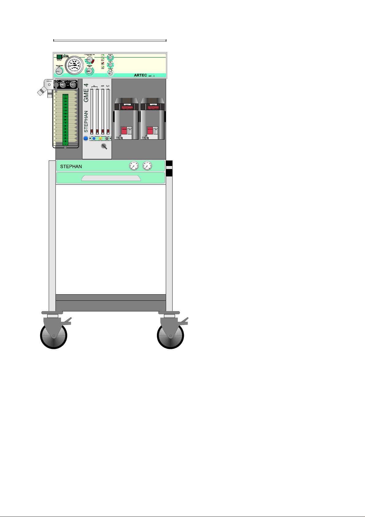
The unit consists of a basic housing of stainless steel in which a drawer is provided.
Located above that is the gas-mix unit (GME, with which the available medical gases O2,
N2O and (optional) compressed air can be dosaged.
The GME consists of an integrated pneumatic unit with relvant safety valves providing for
N20 block and O2 deficiency signal and the dosage unit for the above-mentioned medical
gases.
On the right-hand side, an anesthesia agent specific vaporizer can be mounted on special
mounting racks ( one or two-fold).
Located on the basic unit and depending on model, there is provided a stainless steel shelf
for additional monitoring or a ventilation module with integrated monitoring.
On the reverse side of the unit there are standard connections for gas supply linea and
depending on model, holding racks for reserve bottles with integrated high-pressure
reducers.
The unit is also equipped with four plug sockets for electrical power supply for additional
monitors. These sockets are constantly supplied with current regardless of the Ventilators
ON/OFF power supply status.
2.1 Possible Expansion and Upgrading of the Unit
Basic Model
The ARTEC basic model is suitable for wall mounting. For such mounting, the mounting
rails of the basic unit ar attached to the V2A rails.
For wall mounting, exact vertical mounting of the unit must be strictly observed, otherwise
inexact mounting could lead to falsh measuring results of gas flows. An adjustable
distancer device provides a precise alignment of the unit.
Unit Model with Mobile Stand
The unit can be mounted on a mobile stand that enables and ensures variable site
operation.
The basic unit can be mounted on the mobile stand profile (80x30) by tightening the four
mounting bolts. The mobile stand can be equipped with a stand-alone oxygen,
compressed air and vacuum generator module „STAXEL“
6
Page 7
Operating Instructions Artec
Gas Supply:
The unit is designed with a central gas supply coupling connection. A set of hoses is
supplied with the unit for the three types of gases O
, N2O and compressed air ( if air is
2
provided).
Gas supply can either be via a central gas supply network, or via bottle supply with 10 litre
bottles O2 and N2O. To ensure uninterrupted gas supply, in the event of breakdown of the
central gas supply, 2 litre reserve bottles can be connected.
An alternative to bottled gas supply, the ARTEC anesthesia unit offers the possiblity of a
decentalized oxygen supply via the supply „outlet“. This is the „STAXEL“ that has been
especially developed as an oxygen / compressed air and vacuum generator.
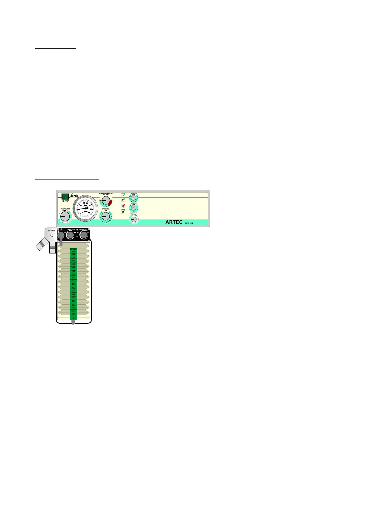
Ventilation Module:
The ventilation module ABVA is
easy to use and can eventually
mounted to the basic unit later on.
For this the V
A shelf is removed
2
from the basic unit. After that the
ventilation module can be mounted
to the basic unit via two mounting
bolts. The compressed air supply of
the ventilator is created via a
connection line to the basic unit.
7
Page 8
Operating Instructions Artec
After attaching the V
A shelf, you now
2
have a respiratory-contolled anesthesia
ventilation system with the current
necessary state-of-the-art monitoring
system.
It is strongly advised to have the
installation carried out by our specially
trained Stephan Service Team.
2.2 Scope of Use and Application
The ARTEC is an inhalation anesthesia unit for the manual anesthesia of infants, children
and adults.
It can be used in conjunction with a ISO circuit system, but can also be operated with open
ventilation systems. The scope of applications of the ARTEC anesthesia unit ranges from
use in the practitioner’s surgery to hospital operation theatres.
8
Page 9
3 Description
N
N
O
6
8
N
O
O
0 ,
0 ,
5
3
0 , 8 9 8 7
0
0 ,
0 , 6
0 , 8
0 , 8
N
0 ,
0 ,
A
5 4 3
4
9 8
7
8
N
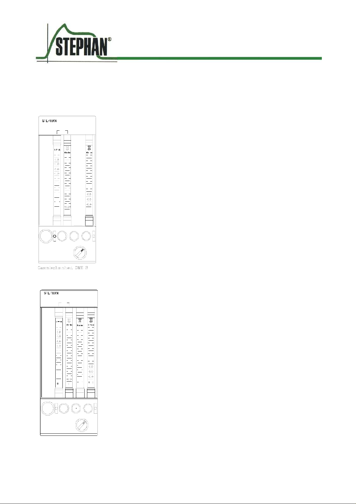
3.1 Gasmixing unit 3 and 4
0 2
The gasmixing unit serves as a dosage unit for medical gases
(e.g. O2, N2O, Air). The choosen gases can mixed in a arbitary
0
2
relation, but the ratio-system guarantees a O2-concentration not
2
1 2
1 1
1 0
1
0 , 6
6
4
4
2
2
2
0 F L U S
2
0
2
A r t . N r . 1 5 0 6 1 0 7 0
0
2
2
2
1 0
1
6
, 4
2
2
2
A I R
1 2
1 2
1 0
lower then 21 % (see below). The different gases are clearly
displayed with rotary buttons.
4
2
1
To avoid mistakes, the O2-rotary button discerns from the others.
A unintentional move is prevented by a protection.
N
2
The dosing device makes a continuous flow enable, when opening
the valves by rotation against clockwise.
0 2
The O2-measuring range contains two measuring devices. This
makes a fine dosage possible.
The left measuring tube has a range from 0 to 2 l/min O2, the right
tube has a range from 2 to 15 l/min O2. As point of observation
serves the upper surface of the floating body.
0
2
The measuring tubes for AIR and/or N2O are laid out as double
1 2
1 0
cone measuring tubes. The lower zone of the measuring tubes
8
6
6
4
4
2
I R
(AIR/N2O) is more finely gradated than the upper.
2
1
The side parts of the GMUE 3/4 can be changed in their dimensions
so it is possible to use different types of measuring tubes (e.g. firm
2
Rota, firm KDG and others).
0 F L
S H 2
0
2
A I R
2
G a s m i
c h e i n h e i t G M E 4
r . 1 5 0 6 1 0 7 1
A r t .
9
Page 10

Operating Instructions Artec
3.2 O2 – Ratiosystem (optional)
The Gasmixing units GME 3 and GME 4 can be equipped optionally with a pneumatical
system to assure at every flowrange of N2O a minimum concentration of oxygen of 25 %
O2 (+/- 5%).
The so called O2 - Ratiosystem avoids the delivery of pure N2O to the breathing system.
Mode of operation
The O
– Ratiosystem examines the O2 – Flowrate. If there is no O2 – Flow the N2O – Line
2
is blocked. Thus it is impossible to apply pure N
O to the breathing system without opening
2
the O2 – Valve at the GME. Only when the O2 – Valve is opened counterclockwise, a N2O
– flow according the flowrate of O2 can be adjusted. The minimal achievable oxygen
concentration is 25 % +/- 5%.
Control of function
1. Close O2 – and N2O – Valve at the GME.
2. Open N2O – Valve to maximum There should be no N2O – Flow
3. Open O2 – Valve counterclockwise N2O – Flow is increasing
For example:
Adjust 1 l/min O2 N2O – Flow should be 3 l/min +/- 0,2 l/min
Adjust 3 l/min O2 N2O – Flow should be 9 l/min +/- 0,6 l/min
The O2 – Ratiosystem controls the O2 – concentration in the freshgas.
It doesent prevent in any case a hypoxic gasmixture in the circlesystem.
Caution
Please do control the inspiratory O2 – concentration by using an
oxygenmonitor.
Caution
10
Page 11

Operating Instructions Artec
3.3 O2-Flush
By pressing the O2 Flush push-button, a fast oxygen supply (approx.
50 litres per minute) is activated directly to the fresh-air outlet (not via
the anesthesia vaporizer).
After releasing the O2 Flush push button it must return to it original
position.
3.4 AIR/N2O Mode Switch
The Air / N2O Mode Switch is located below the rotary knobs for (AIR
/N2O). This offers a pre-selection of the gases AIR or N2O. The
respective dosage of the gases is effected via the regulation valve.
3.5 O2- supply deficiency signal
In the event of a pressure drop in the supply system (oxygen below
2.0 to 1.5 bar) an acoustic warning alarm is activated for a duration
of at least 7 seconds. An interruption is not possible).
3.6 Nitrous Oxide Block
In the event of a further fall in presure of oxygen to about 1 bar,the ratio of N2O is reduced
proportionately to the oxygen supply. Should there be a total fallout of oxygen, the N20 flow
is set to zero. Release of N2O is then closed.
The unit stand-by mode can be resumed only by setting the stipulated oxygen pressure of
at least 2 bar at the network inlet.
11
Page 12
Operating Instructions Artec
3.7 Vaporizer
On request, the ARTEC inhalation anesthesia unit can be equipped with various vaporizersystems. In the standard model, the vaporizerss come in use which are equipped with an
„Interlock‘“ locking system to enable alternating operation of two vaporizers.
The anesthetic agent is mounted to the
selected vaporizer rack by means of a click-in
mechanism. The locking lever secures the
vaporizer on the holding rack.
Please read the operating instructions of the
respective model of vaporizer with which the
ARTEC anesthesia unit is equipped.
Vaporizer holding-rack „single“
The unit is equipped with one vaporizer rack holder. Only one vaporizer can be put into
operation.
The vaporizer holding rack is provided with automatic closing valves. The seal between the
vaporizer and the holding rack takes on the function of a gasket ring placed on the valve.
Optionally, a side-rail possiblity for a second vaporizer can be provided besides the active
vaporizer holding rack.
Vaporizer holding rack „two-fold“ Interlock locking system:
The unit is provided with two vaporizer
holding racks. Two vaporizers can be
alternately used. The vaporizers are provided
with locking devices that disables the
vaporizer that is not in operation
Interlock
.
12
Page 13

Operating Instructions Artec
3.8 Gas-cylinder Supply Component
When in the gas-cylinder operation mode, the gas is reduced from 200 or 50 bar to a
working pressure of 5 bar. The cylinder pressure can be read on the pressure gauge and
indicates the status of level fill of the gas bottles.
The feed of the gases to the actual unit is effected via the quick-fit couplings or the DIN
threaded couplings which are unmistakeably coded according to type of gas being used.
When transporting, it is absolutely necessary to close the cylinder-valves.
Caution
13
Page 14

Operating Instructions Artec
4 Changeover mounting arm (optional)
As an option, the anesthesia system can be equipped with a changeover mounting arm. At
the fresh gas outlet of this mounting arm a circuit system ISO 1 (Art.Nr. 11561006 / rebreathing system with CO2 absorber) or all commercially available non re-breathing
systems (e.g. Magill, Mapelson, Bain etc.) can be connected.
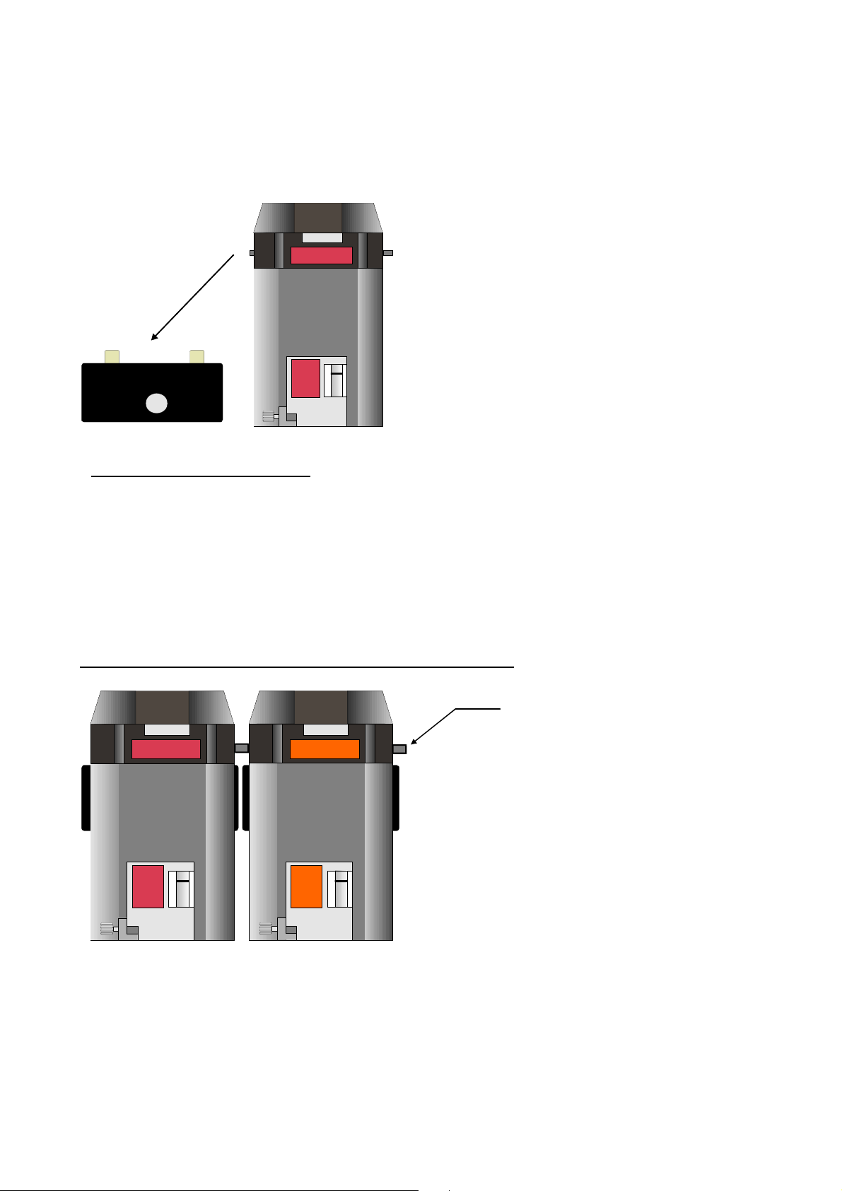
4.1 Top view
Fig. 1: Top view
1 Circuit system holder 4 Fresh gas outlet
2 Safety valve,
connection for
anesthetic gas
aspiration Ø 28 mm
3 Fastening point
anesthesia system
5 Adapter for O2 sensor when
using a non re-breathing
system
(Must be sealed with the cap
when using a circuit system
/re-breathing system)
14
Page 15

4.2 Front view
Fig. 2: Front view
Operating Instructions Artec
4 Fresh gas outlet 6 Fresh gas inlet coming
from the gas mixing unit
(GMU)
5 Adapter for O2 sensor when
using a non re-breathing
system (Must be sealed
with the cap when using a
circuit system /
re-breathing system)
15
Page 16

4.3 Rear view
Operating Instructions Artec
Fig. 3: Side view on the left
2 Safety valve, connection for
anesthetic gas aspiration Ø
28 mm
5 Adapter for O2 sensor when
using a non re-breathing
system
(Must be sealed with the
cap when using a circuit
system /
re-breathing system)
6 Fresh gas inlet coming
from the gas mixing unit
(GMU)
16
Page 17

Operating Instructions Artec
4.4 Connecting the changeover mounting arm
4.4.1 Connection to the circuit system (re-breathing system)
Fig. 4: Connection to the changeover mounting arm
4 Fresh gas outlet 6 Fresh gas inlet coming from
the gas mixing unit (GMU)
5 Adapter for O
when using a non re-
sensor
2
7 Connection hose for circuit
system
breathing system
(Must be sealed with the
cap when using a circuit
8 Fresh gas inlet of the circuit
system
system /
re-breathing system)
Proceed as follows to connect the mounting arm to the circuit system:
Connect the fresh gas outlet of the GMU with compressed air hose to fresh gas inlet
of the mounting arm (It. 6).
Attach connection hose of the circuit system (It. 7) to fresh gas outlet of changeover
mounting arm.(It. 4).
17
Page 18

The adapter for O2 sensor must be sealed with the cap when using a circuit
system /re-breathing system.
Caution
4.4.2 Connection to a non re-breathing system
Operating Instructions Artec
Fig. 5: Connection of the mounting arm to a non re-breathing system
4 Fresh gas outlet 6 Fresh gas inlet coming from
the gas mixing unit (GMU)
5 Adapter for O2 sensor
when using a non re-
7 Connection hose for circuit
system
breathing system
(Must be sealed with the
cap when using a circuit
8 Fresh gas inlet of the circuit
system
system /
re-breathing system)
18
Page 19

Operating Instructions Artec
Proceed as follows to connect the mounting arm to a commercially available non rebreathing system (e.g. Magill, Mapelson, Bain etc.) proceed as follows:
Remove the connection hose for circuit system ( It. 7) from the fresh gas outlet of
the mounting arm (It. 4).
Connect the non re-breathing system to the fresh gas outlet of the mounting arm
(It. 4).
When using a non re-breathing system, an O2 sensor must be connected to
the adapter (It. 5).
Caution
When using a non re-breathing system, the APL valve of the circuit system
fastened to the mounting device is not active. This is why it is advisable to use
Caution
non re-breathing systems with integrated APL valve.
19
Page 20

Page 21

5 Testing Unit Functions
5.1 Dosage valves of the Gas Mix Unit
When closing the dosage valves make sure that the respective floating marker of the
respective measuring tubes are re-set to zero. Otherwise, a leakage of the respective
spindle will result that must be remedied by a service technician.
5.2 O2-Flush
Before each operation of the ventilation unit check to see whether the O2 bypass valve
immediately and automatically closes after releasing the push-button.
Basic Setting:
Dosage valve (1) on measuring tube section is closed.
Conducting Test:
Briefly press the bypass button. On release of the push-button it immediately return to its
initial position.
5.3 AIR / N2O Mode Switch
Basic Setting:
O2 dosage valve closed
N2O dosage valve set to 3 litres per minute
AIR dosage valve set to 3 litres per minute
Mode Switch in „N2O“ position
Anesthesia aspiration unit connected
O2 monitor calibrated and in operating mode
Conducting Test:
The measuring tubes for N2O must show 3 litres per minute flow, while the compressed
measuring tube must indicate no flow. The O2 monitor shows approx. 0% O2 (after a brief
waiting time).
When switching from N2O to AIR – without changing dosage valve status – indication of
floating marker of the N2O measuring tube must return to zero, while, at the same time the
display of the compressed-air measuring tube must indicate 3 litres per minute. The O2
monitor shows 21% O2 as comfirmation.
21
Page 22

Page 23

6 Gas Type Test and Testing Safety Devices
6.1 Testing Gas Type:
Check for proper connection of the anesthesia unit to the central gas supply system before
operation of the unit.
Basic Setting:
Unit in operation mode
Anesthesia gas aspiration unit connected
O2 monitor in standby mode and calibrated. Measuring at fresh gas outlet.
Conducting the test:
Oxygen ( O2):
Open the O2 dosage spindle to approx. 1.5 to 2.0 litres per minute.
The O2 monitor must display approx. 98 to 99 O2.
Nitrous Oxide (N2O):
When using an Artec with N2O, close the Air dosage valve and open the N2O valve. Check
the N2O concentration with an external anesthesia gas module.
Compressed air (AIR)
Open the AIR dosage spindle to approx. 1.5 to 2.0 litres per minute
The O2 monitor must display approx. 21% O2
Danger
In the event of any deviance, the unit must undergo a service inspection!
23
Page 24

Operating Instructions Artec
6.2 Testing the O2 deficiency signal / nitrous oxide block:
Basic Setting:
Unit in operation mode
Anesthesia aspirator device connected
All dosage valve spindles opened to 3 litres per minute
AIR / N2O Mode Switch in N2O position
Conducting test:
Remove angle plug for O2 from circuit
The oxygen flow must continuously decrease
At apprix. 2.0 to 1.5 bar circuit pressure the O2 deficiency signal is activated
When pressure further decreases to approx. 1 bar, the nitrous oxide block is activated
and the N2O flow sinks parallel to the oxygen flow, until for a fully empty system both
volumen flows fall to zero.
By re-connecting the O2 angle plug, the oxygen supply is re-established.
Interruption of the N2O feed line. The N2O flow sinks to zero.
In the event of deviations of the description above, please inform customer
service.
Danger
6.3 Testing the Vaporizer / Vaporizer holding rack
The anesthesia agent vaporizer is to be check for its proper function before using the unit.
Basic Setting:
Unit set in operation mode
Anesthesia agent vaporizer filled and ready for operation
Conducting the test:
Vaporizer:
Check adjusting and locking device for proper functioning
Check level status display for damage
Check adapter for safety support for damage
Check vaporizer locking lever
Condition of Vaporizer:
Check sealing valve for leakage
Inspect sealing gasket for exterior damage
24
Page 25

7 Cleaning and Care of Anesthesia Unit
The anesthesia unit is to undergo a thorough cleaning at appropriate intervals; whereby
servicing measures must also be conducted that will prolong the service life of the
machine.
After removing the vaporizer, the unit can be wiped clean using a common detergent
agent. It is highly recommended to follow this up by using a dry cloth to remove any
moisture and thus limiting any danger of corrosion.
Special attention should be given to the O-rings located at the vaporizer holding rack.
These are to be carefully removed, cleaned and replaced in a dry condition.
Should these rings show damage of any type, they are to be replaced by new O-rings.
For the changeover mounting arm no maintenance work is required. Parts of the
changeover mounting arm should only be replaced or repaired by the customer service of
F. STEPHAN GMBH.
25
Page 26

8 Troubleshooting
8.1 ARTEC
Error Possible Cause(s) Remedy
Floating marker of the
measuring tubes do
not return to zero
Operating Instructions Artec
Measuring tube is dirty Clean measuring tube
Dosage valve leakage Loosen rotary knob and re-set
(Service)
When using Mode
Switch AIR/N2O
switch, the selected
gas is not activated
(indicated via O2
monitor)
Oxygen concentration
too high
O2 deficiency signal
is constantly activated
Mode switch valve is not
properly sealed.
Leakage in oxygen dosage
valve
Flush Valve does not close
properly
Supply pressure too low Set pressure reducer of the
Valve is defect Have customer serve replace
Replace mode switch valve
(customer service)
Loosen rotary knob and re-set
(customer service)
Replacement of Flush Valve
by customer service
bottle supply higher
valve
26
Page 27

8.2 Changeover mounting arm (if available)
Störung Ursache Mögliche Fehlerbeseitigung
Operating Instructions Artec
When using the circuit
system:
No or not enough
fresh gas supplied to
the circuit system
When using a non rebreathing system:
No or not enough
fresh gas supplied to
the non re-breathing
system
Connection hose of the
circuit system is not
connected to the fresh gas
outlet of the mounting arm
Setting for fresh gas flow is
too low at the gas mixing
unit (GME)
Supply hoses at the
changeover mounting arm
are not correctly connected
or not properly fastened
Wrong setting of APL valve Check setting of APL valve
Connection hose of the non
re-breathing system is not
connected to the fresh gas
outlet of the mounting arm
Frischgasstrom an der
Gasmischeinheit (GME) ist
zu niedrig eingestellt
Supply hoses at the
changeover mounting arm
are not correctly connected
or not properly fastened
Attach the connection hose of
the circuit system to the fresh
gas outlet of the mounting
arm
Adjust correct setting for fresh
gas flow at the GMU
Check the connection of the
supply hoses at the
changeover mounting arm; if
necessary, connect and
fasten correctly
Attach the connection hose of
the re-breathing system to the
fresh gas outlet of the
mounting arm
Adjust correct setting for fresh
gas flow at the GMU en
Check the connection of the
supply hoses at the
changeover mounting arm; if
necessary, connect and
fasten correctly
Wrong setting of APL valve Check setting of APL valve
27
Page 28

Page 29

9 Technical Data
Inhalation Anesthesia Unit MPG-Class 2b, Model Registration Number: 11 / M-01491
Typ: B Protection Class: 1
U: 230 V AC
P: 80 VA (with ventilator)
Dimensions (with Ventilator ABVA)
Width: 500 mm
Height: 1350 mm
Depth: 630 mm
Dimensions (without Ventilator ABVA)
Width: 500 mm
Height: 1240 mm
Depth: 630 mm
Connections (threaded) for Gas Types:
O2: M 12 x 1
AIR: M 20 x 1.5
N2O: M 14 x 1
Fresh Gas: M 16 x 1.5
Circuit pressure 5 bar +/- 0.5 bar
Measuring range for measuring hoses:
O2 (fine) : 0 to 2 litres per minute
(roughly) : 2 to 15 litres per minute
AIR : 0 to 15 litres per minute
N2O : 0 to 15 litres per minute
Precision of Measuring tubes:
+/- 10% of the respective end scale value. For integrated micro measuring range +/- 10%
of the measuring endscale value (under standard conditions 20ºC and 1.013 bar)
O
deficiency signal:
2
Trigger pressure: 2.8 bar
Duration of acoustic warning signal 7 seconds
N2O Block:
Trigger pressure: 2.0 bar
29
Page 30

Page 31

10 Maintenance and Servicing
10.1 Artec
Medico-technical products and required to undergo at regular intervals inspection and
servicing in compliance with MedGV (Medical Equipment Regulations).
Such inspections and servicing are to be carried out by authorized personnel only (Service
Staff) of the Supplier.
Periodic Maintenance is genenally semi-yearly.
Safety Technical Inspections
Recommended Scope:
1. Visual check of necessary identification markings and Exterior detected damage
2. Check for completeness of Unit
3. Check proper functioning and alarm functioning
4. Measure earthing resistance, replacement unit ground contact and the insulation
resistance in comliance with VDE 0751 Part 1/12.84
The Maintenance Agreement ensures the best guarantee, and provides semi-annual
inspections with automatic replacement of parts subject to wear.
Should maintenance and servicing of the unit be carried out by unqualified and
unauthorized persons, the Manufacturer cannot be held reliable for the safe and proper
functioning of the unit.
10.2 Changeover mounting arm (if available)
For the changeover mounting arm no maintenance work is required. Parts of the
changeover mounting arm should only be replaced or repaired by the customer service of
STEPHAN GMBH.
F.
31
Page 32

Operating Instructions Artec
F. Stephan GmbH
- Medizintechnik Kirchstrasse 19
56412 Gackenbach
(+)49 (6439) 9125 – 0
(+)49 (6439) 9125 – 111
info@stephan-gmbh.com
www.stephan-gmbh.com
32
 Loading...