

Page 1
N
N
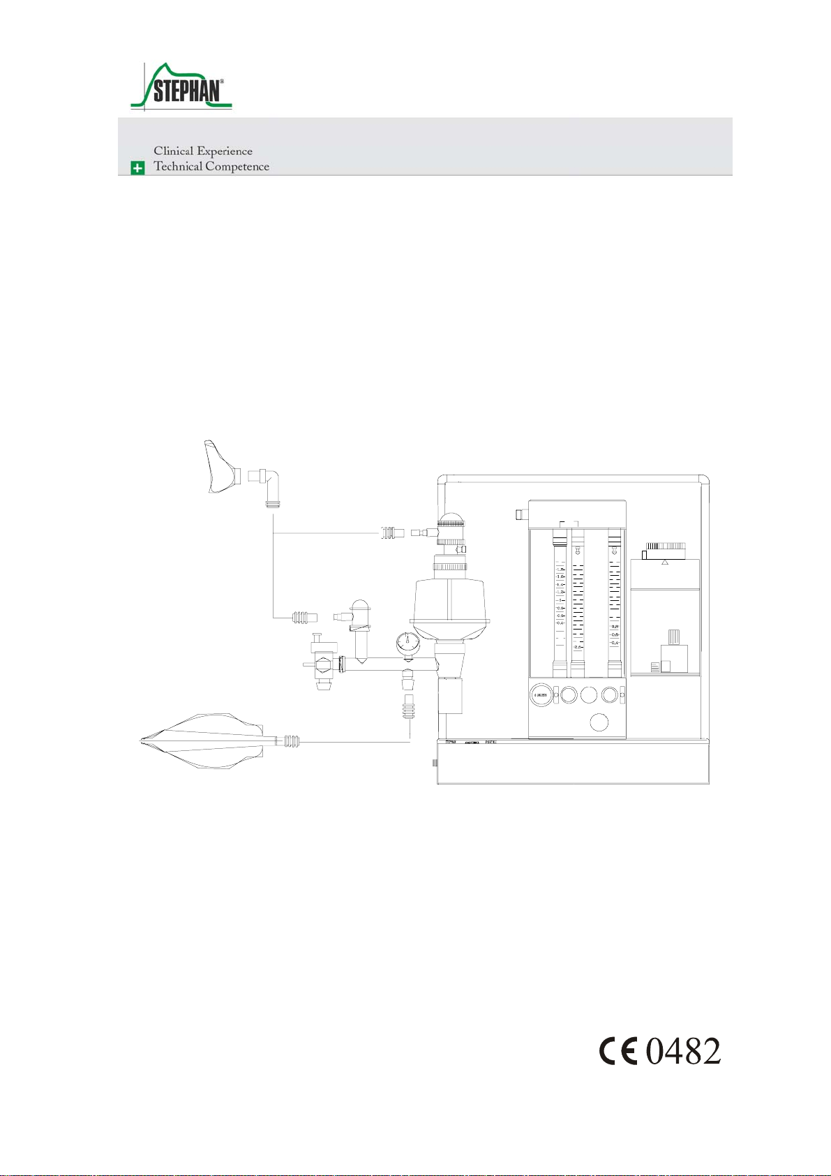
Artec / Portec
Anaesthesia Apparatus
S T E P H A N
0
2
0 , 2
O
2
0
A N E S T H E S I E G M E 2
2
1 2
1 1
1 0
9
8
7
6
5
4
3
2
2
0
2
0 1
2
1 2
1 0
8
6
4
2
1
O N
2
0
2
O F F
Service Instructions
Page 2

Preface
Service Instruction
Please carefully read each step of the procedure that is to be carried out
before beginning the servicing of the unit. Always use the correct tools
and the indicated measuring instruments. Any non-compliance with the
instructions and/or recommendation found in this technical
documentation can lead to a malfunctioning of the equipment or damage
to it.
Use only original replacement parts as supplied by F. S
TEPHAN GMBH,
and that are listed in the Replacement Parts List.
This technical documentation is not to be used in place of the operating
instructions. Each operation and handling of the equipment requires exact
knowledge and observance of the operating instructions. This equipment
is only to be used for the stipulated application.
F. Stephan GmbH
F. Stephan GmbH
- Medizintechnik -
- Medizintechnik Kirchstrasse 19
Kirchstrasse 19
56412 Gackenbach, Germany
56412 Gackenbach, Germany
Subject to technical changes. Subject to technical changes.
Stand: April 1999 Status: April 1999
Version: V1.2
Version: V1.2
2 SA-103-0499V1.2-STJ-GB © F. Stephan GmbH
Page 3

®
Table of Contents
Table of Contents.......................................................................................3
1 General Information...........................................................................7
1.1 Equipment designation and manufacturer...............................7
1.2 Technical safety inspections....................................................7
1.3 Maintenance.............................................................................7
1.4 Warranty..................................................................................8
2 Connections on part of the supply system .........................................9
2.1 Check of the plug-in gas couplings O2, N2O, AIR for:............9
2.2 Check of the gas connection tubes O2, N2O, AIR, for:............9
2.3 Check of the screw joints of the connecting threads O2, N2O,
Table of Contents
AIR for:....................................................................................9
2.4 Check of the female connecting threads O2, N2O, AIR for:..10
3 Description of Design and Performance..........................................11
3.1 Gas-mixing-unit 2 and 3 (GME 2/GME 3)............................11
3.1.1 O2-Flush ....................................................................12
3.1.2 AIR / N2O-Change-Over...........................................12
3.1.3 Nitrous Oxide Blocking.............................................13
4 Vaporizer, Vaporizer holding device...............................................15
4.1 Vaporizer...............................................................................15
4.2 Vaporizer holding device.......................................................15
5 Cylinder Supply Unit.......................................................................17
6 Circle System...................................................................................19
6.1 Design and Description of Performance................................19
6.1.1 CL (closed)................................................................20
6.1.2 Pressure Range from 5mbar to 50mbar.....................20
6.1.3 Spontaneous Respiration...........................................20
6.1.4 VOL (volume-controlled ventilation) .......................20
6.1.5 Circle System ............................................................21
7 Performance Test.............................................................................23
7.1 Execution of the Test.............................................................23
7.2 O2-Flush.................................................................................24
7.3 Air / N2O-Change Over (Basic setting).................................24
7.3.1 Execution of the Test.................................................24
© F. Stephan GmbH SA-103-0499V1.2-STJ-GB 3
Page 4

Table of Contents
7.4 Check of types of gas and test of the safety devices.............. 25
7.4.1 Execution of the Test.................................................25
7.4.2 Proportioning Valves.................................................25
7.5 Tightness of the Circle System.............................................. 26
7.5.1 Basic setting ..............................................................26
7.5.2 Execution of the Test.................................................27
7.6 Test of the pressure-regulating valve.....................................27
7.6.1 Basic setting ..............................................................28
7.6.2 Execution of the Test.................................................28
7.7 Test of inspiration-and expiration valve................................29
7.7.1 Basic setting ..............................................................29
7.7.2 Execution of the Test.................................................29
8 Diagram of pneumatic control system.............................................31
8.1 Pneumatic control system O2 / N2O / AIR.............................31
8.2 Pneumatic control system O2 / N2O.......................................32
9 Troubleshooting Guide ....................................................................33
9.1 Portec.....................................................................................33
9.2 Circle System.........................................................................34
10 Technical Data.................................................................................35
10.1 Dimensions............................................................................35
10.2 Type of gas connections........................................................35
10.3 Measuring range of the flowmeter tubes ...............................36
10.4 Accuracy of the flowmeter tubes...........................................36
10.5 O2-Failure alarm ....................................................................36
10.6 Technical Data Circle System ...............................................36
11 List of spare parts.............................................................................37
11.1 Circle system .........................................................................37
11.1.1 Semi-annual servicing circle system.........................38
11.2 Absorber ................................................................................39
11.2.1 Semi-annual servicing Absorber...............................39
11.3 Expiration valve.....................................................................40
11.3.1 Semi-annual servicing expiration valve....................40
11.4 Inspiration valve....................................................................41
11.4.1 Semi-annual servicing inspiration valve ...................42
11.5 Artec / Portec.........................................................................42
11.6 Vaporizer...............................................................................44
4 SA-103-0499V1.2-STJ-GB © F. Stephan GmbH
Page 5

®
Table of Contents
11.7 Flowmeter tube......................................................................45
11.8 Spindle 46
11.9 Instruction Flowmeter tube....................................................48
12 Measuring of electrical power leakage............................................51
13 Servicing..........................................................................................53
14 Test Certificate.................................................................................55
15 Acceptance of the apparatus ............................................................57
16 Index of Figures...............................................................................59
17 Index of Tables ................................................................................61
18 Notes 63
© F. Stephan GmbH SA-103-0499V1.2-STJ-GB 5
Page 6

Page 7

®
1 General Information
1 General Information
1.1 Equipment designation and manufacturer
Equipment designation
Manufacturer
Artec /Portec
F. Stephan GmbH
- Medizintechnik Kirchstrasse 19
56412 Gackenbach, Germany
(+)49 (6439) 9125 – 0
(+)49 (6439) 9125 – 111
info@stephan-gmbh.com
www.stephan-gmbh.com
1.2 Technical safety inspections
Technical safety inspections are to be carried out every six months by the
manufacturer or an authorized Technical Service Team of F. S
GMBH.
1.3 Maintenance
For reasons of equipment safety and reliable functioning, it is
recommended that the maintenance of the inhalation anesthesia units,
A
RTEC / PORTEC, also be carried out in conjunction with the semi-
annual technical safety inspections.
Maintenance is to be carried out only by a service team authorized by F.
S
TEPHAN GMBH.
When carrying out maintenance or servicing, use only those replacement
parts that are supplied by F. S
TEPHAN GMBH.
TEPHAN
© F. Stephan GmbH SA-103-0499V1.2-STJ-GB 7
Page 8

1 General Information
1.4 Warranty
The manufacturer grants a 24-month warrant effective from the date of
purchaser.
Any modification or repair work carried out on the equipment may only
be done by F. S
Otherwise the warranty becomes invalidated.
In validation of the warranty can also arise through improper handling
and opertion of the equipment.
TEPHAN GMBH or an authorized technical team.
Claims
Warranty claims that can be attributed to improper operation, insufficient
care and maintenance shall not be honored by the manufacturer.
The manufacturer guarantees only for the safety and reliable operation of
the equipment only if the operating and servicing instructions are strictly
adhered to.
8 SA-103-0499V1.2-STJ-GB © F. Stephan GmbH
Page 9

®
2 Connections on part of the supply system
2 Connections on part of the supply
system
2.1 Check of the plug-in gas couplings O2, N2O, AIR for:
correct color coding
correct fit in the gas socket
external damage
2.2 Check of the gas connection tubes O2, N2O, AIR, for:
correct connection of the plug-in gas coupling
correct connection to the screw joint of the connecting thread
correct color coding
external damages
2.3 Check of the screw joints of the connecting
threads O
, N2O, AIR for:
2
Tightness
correct color coding of the individual types of gas
damage to the thread
© F. Stephan GmbH SA-103-0499V1.2-STJ-GB 9
Page 10

2 Connections on part of the supply system
2.4 Check of the female connecting threads O2, N2O, AIR for:
firm fit
correct coding of the threads of the individual appliances
correct color coding on the foil
damage to the thread
10 SA-103-0499V1.2-STJ-GB © F. Stephan GmbH
Page 11
®
3 Description of Design and Performance
3 Description of Design and Performance
3.1 Gas-mixing-unit 2 and 3 (GME 2/GME 3)
0
0
2
2
12
11
10
9
1
8
0,8
7
0,6
6
0,4
5
4
0,2
3
O
O
2
2
N 0
N
2
12
10
8
6
4
2
1
O
2
2
2
12
11
10
9
1
8
0,8
7
0,6
6
0,4
5
4
0,2
3
2
2
AIR
12
10
0,8
0,6
0,4
0,2
AIR
N 0
2
12
10
8
8
6
6
4
4
2
2
1
1
2
0 FLUSH
2
2
0
N 0
2
0 FLUSH
2
AI R
0
2
N 0
2
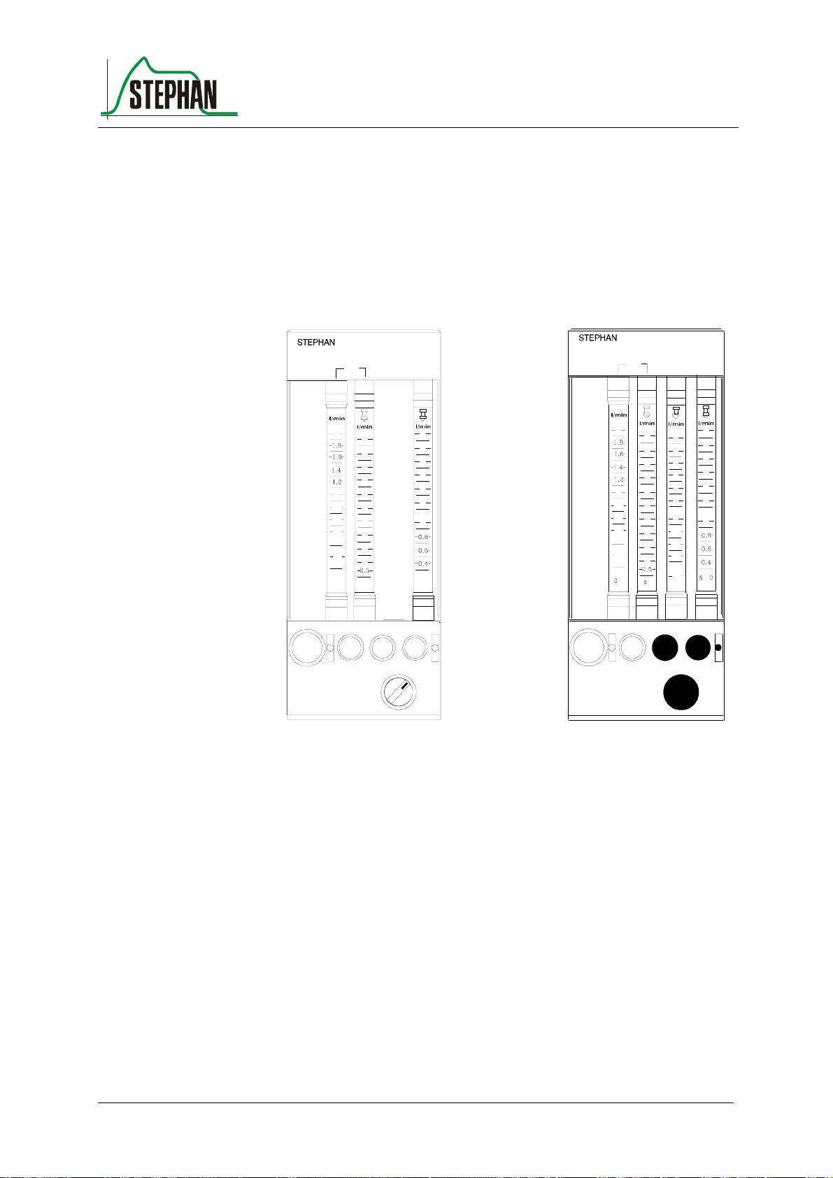
Fig. 1: GME 2 Art.Nr.: 1 150 61 070
GME 3 Art.Nr.: 1 150 61 071
he gas-mixing unit serves as proportioning device for medical gases
T
(e.g. oxygen, nitrous oxide and compressed air).The desired gases can be
mixed in any relation by means of the proportioning valves below the
flowmeter tubes. The types of gas can be clearly recognized on the
control knobs.
To prevent conf
usion, the control knob of the regulating valve for oxygen
differs haptically from the two other valves. Inadvertent shift of the
settings is avoided by a special twisting-prevention device.
he proportioning valves (control knobs) permit a continuous flow, when
T
they are rotated counterclockwise. The measuring area for O
consists of
2
two flowmeter tubes, so that an exact proportioning is guaranteed.
© F. Stephan GmbH SA-103-0499V1.2-STJ-GB 11
Page 12
3 Description of Design and Performance
The high precision flowmeter tube (at the left) indicates the measuring
range from 0 to 2 l/min, the "rough" flowmeter tube (at the right)
indicates the flow quantities from 2 to 15 l/min.
Reading line is the upper edge of the float. Graduation of the lower scale
parts of the measuring tubes (AIR/N
Because the dimensions of the lateral parts of the GME 2/3 can be altered
optionally, the use of flowmeter tubes of other manufacturers (e.g. Rota,
KDG and others) is possible.
O) is more closely stepped.
2
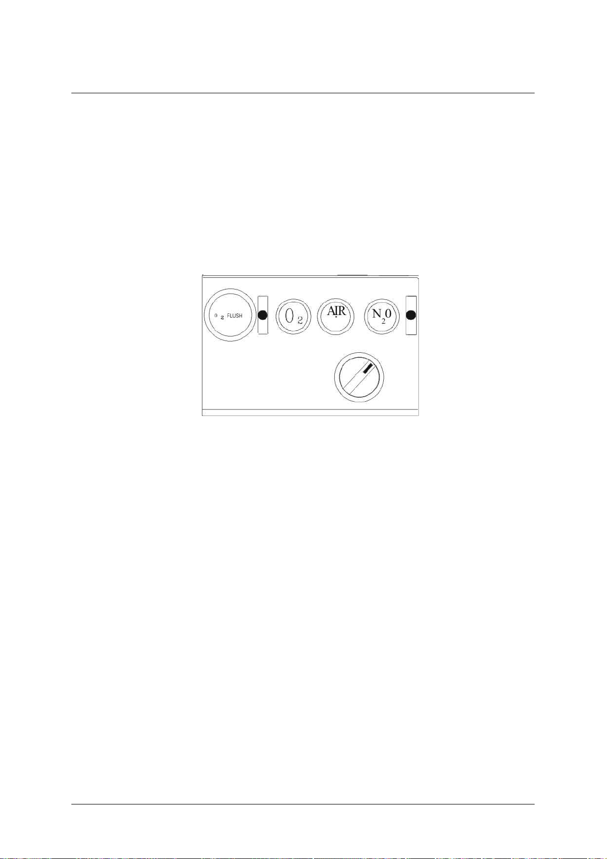
Fig. 2: Gas Mixing Unit
3.1.1 O2-Flush
Depressing the O
-flush-button effects a quick oxygen supply
2
(approximately 50 l/min) directly to the outlet for fresh gas ( not via the
vaporizer for anaesthetic agent).
Releasing the O
-flush-button effects return to the initial position.
2
3.1.2 AIR / N2O-Change-Over
The AIR/N
knobs (AIR/N
possible. The appropriate proportioning of the gases is carried out by
means of the regulating valves O
In case of a decrease of pressure in the supply system (oxygen
lower than 2,8 bar ) an audible alarm sounds for at least 7 seconds.
No muting is possible.
O-change-over-switch is situated below the respective control
2
O). It makes preselection of the gases AIR or N2O
2
-Failure Alarm.
2
12 SA-103-0499V1.2-STJ-GB © F. Stephan GmbH
Page 13

®
3.1.3 Nitrous Oxide Blocking
If pressure of oxygen further decreases to approximately 2 bar,the portion
of N
O is also reduced proportionally to the portion of oxygen. In case of
2
a total failure of oxygen supply, the flow of N
The readiness for service of the apparatus can only be restored by
providing the prescribed pressure of oxygen of at least 2 bar at the
connection with the supply system.
3 Description of Design and Performance
O is reduced to zero.
2
© F. Stephan GmbH SA-103-0499V1.2-STJ-GB 13
Page 14

Page 15

®
4 Vaporizer, Vaporizer holding device
4 Vaporizer, Vaporizer holding device
4.1 Vaporizer
Check setting wheel and stop for performance
Check indication of filling level for damage
Check drain screw for easy running and tightness
Check performance of safety filling socket for performance
Check locking device of vaporizer
Verify concentration values of the vaporizer with the help of a testing
device for anaesthetic gases
maximum admissible tolerance in accordance with DIN 13252: +/-
20% of the set value or 0,2 Vol % absolute, always the higher value of
the two.
4.2 Vaporizer holding device
Check sealing valves for tightness
Exchange O-rings
Check for firm fit
© F. Stephan GmbH SA-103-0499V1.2-STJ-GB 15
Page 16

Page 17

®
5 Cylinder Supply Unit
Performance test of the high-pressure gauges for N
Check of the connections for supply cylinders
Check of correct coding of threads
Check of the packings of the supply cylinders
Check screw joints and pipe installations for tightness and damages
Check housing for damages
Check attached components for firm fit
5 Cylinder Supply Unit
O and O2
2
© F. Stephan GmbH SA-103-0499V1.2-STJ-GB 17
Page 18

Page 19

®
6 Circle System
6.1 Design and Description of Performance
The circle system together with the patient forms a closed cycle, into
which fresh gas is fed via the fresh gas pipe line. Excess gas escapes
through the excess gas valve (10)from the cycle and is removed from the
field of activity of the anaesthetist by means of the suction system for
anaesthetic gas (13).During the inspiration phase, the gas contained in the
system is transported to the patients' lungs by effecting pressure,
produced either by the respirator or by manual operation of a respiratory
bag. The consequent PRESSURE RELIEF in the system during the
expiration phase and the increase of pressure in the lungs due to the
elasticity of the thorax makes the gas flow back out of the lungs. Thereby
it is the task of the inspiration valve (1) and the expiration valve (7) to
permit the flow of gas only in one direction and so to establish the cycle.
Prior to reaching the patient again, CO
(2). Humidity and heat given off by the patient are fed back to him in
such a semi-closed system, which prevents desiccation and excessive
cooling of the airways. The fresh gas feeder is located on the lower end of
the holding tube. The adjustability of elevation and the possible
swivelling stand for a good adaptation to the local conditions of the
operating theatre. The respiratory pressure gauge(3), which can be
slipped onto the holding device of the circle system, has a measuring
range from - 10 to 100 mbar. It can be replaced by a blind plug.
is removed in the two absorbers
2
6 Circle System
As a standard, a mechanic volumeter (9) is installed below the expiration
valve, which measures all expiratory values of respiratory volume. The
measuring of O
in accordance with DGAI, is carried out by means of a polarographic cell
(by Clark) (1) at the head of the inspiration valve. Moreover, the circle
system is provided with connection tapers in accordance with ISO
respectively DIN 13 252, so that corrugated tubes for the ventilation of
adults as well as tube systems for infants can be used. The excess valve
(10) serves to carry off spent respiratory gases. It can be operated in four
different adjustments.
© F. Stephan GmbH SA-103-0499V1.2-STJ-GB 19
-concentration, required
2
Page 20

6 Circle System
6.1.1 CL (closed)
The valve is completely closed. This setting is necessary for operation in
respirator mode. In this mode, the spent respiratory gases are evacuated
via the ejector on the patient component during the expiration phase.
6.1.2 Pressure Range from 5mbar to 50mbar
This setting is used to limit the maximum pressure during manual
ventilation. When the set pressure is reached, the valve evacuates.
6.1.3 Spontaneous Respiration
During spontaneous respiration of the patient under light anaesthesia, the
valve closes in the inspiration phase, the patient now breathes the fresh
gas provided by the apparatus. In the expiration phase, the valve opens
and evacuates the system until ambient pressure is reached.
This setting is to be used in case of assisted ventilation with the patient
triggering the respiration and the respirator deepening the respiration.
Aside of that, it is possible to switch to SP briefly in case of manual
ventilation in the pressure range of 5 to 50 mbar to evacuate an overfilled
respiratory bag.
6.1.4 VOL (volume-controlled ventilation)
With the valve setting VOL, the circle system is closed automatically to
guarantee supply of the patient with the desired respiratory working
volume. Spent and excess respiratory gases escape from the valve at the
end of the expiration phase. During the expiration phase, pressure in the
system never rises above 1,5 mbar.
20 SA-103-0499V1.2-STJ-GB © F. Stephan GmbH
Page 21

®
6.1.5 Circle System
Check performance of inspiration- and expiration valve and contact
surfaces of the valves for damages
Check tapers and taper seats for damages
Check absorber for damages and tightness
Check performance of respiratory pressure gauge
Check setting values and performance of the Berner-valve
Check fresh-gas-feed for passage of flow and tightness
Check tube system, Y - piece and mask
In the course of semi-annual servicing, all packings and O-rings must
be exchanged.
6 Circle System
© F. Stephan GmbH SA-103-0499V1.2-STJ-GB 21
Page 22

Page 23

®
7 Performance Test
Fig. 3: Gas Mixing Unit
Proportioning valves (1) on flowmeter unit closed
7 Performance Test
7.1 Execution of the Test
Cautiously open the proportioning spindle for oxygen while
observing the respiratory pressure gauge (2). Fill pipe line system,
until the respiratory pressure gauge comes to a standstill at constantly
60 mbar.
The float of the oxygen flowmeter now indicates the dimension of the
leakage.
Fig. 4: Proportioning spindle for oxygen
© F. Stephan GmbH SA-103-0499V1.2-STJ-GB 23
Page 24

7 Performance Test
7.2 O2-Flush
Attention
Do not use in the application described above. You will destroy the
manometer.
Prior to putting the apparatus into service, it must be verified, that the O
flush-valve closes immediately and automatically after the key has been
released. For this test, the flush-key must be depressed briefly. When
released, it must return immediately to its initial position.
7.3 Air / N2O-Change Over (Basic setting)
O
- proportioning valve closed
2
N
O-proportioning valve set at 3 l/min
2
Proportioning valve for AIR set at 3 l/min
Change-over-switch in "N
Suction system for anaesthetic gas connected
O
-monitor calibrated and in operation
2
7.3.1 Execution of the Test
O" – position
2
-
2
The flowmeter tube for N
O must indicate 3 l/min, while the
2
flowmeter tube for compressed air must give a reading of zero. The
O
-monitor indicates ca. 0% O2 ( after a brief delay ).
2
When changing over from N
O to AIR (Change-over-switch)
2
without altering the settings of the proportioning valves
the float of the N
O-flowmeter tube must return to zero, while in
2
parallel the reading of the flowmeter tube for compressed air must
rise to 3 l/min. As a confirmation, the O
21 % O
.
2
-monitor shows a reading of
2
24 SA-103-0499V1.2-STJ-GB © F. Stephan GmbH
Page 25

®
7 Performance Test
7.4 Check of types of gas and test of the safety devices
(Nitrous oxide blocking and O
Apparatus in operating mode
Suction system for anaesthetic gas connected
Spindles of all proportioning valves opened to 3 l/min
Change-over-switch for AIR/N
7.4.1 Execution of the Test
Separate angular plug for O
The flow of oxygen must decrease continuously
-failure-alarm)
2
O in N2O-position
2
from supply system
2
The O
-failure alarm sounds, when line pressure reaches approximately
2
2,8 bar
When pressure further decreases to approximately 2 bar, the nitrous-
oxide-blocking must set in and lower the N
oxygen flow, until, with the system completely emptied, both volume
flows have decreased to zero.
Oxygen supply is restored by inserting the angular O
When the N
O-supply is interrupted, only the N2O-flow drops to zero
2
After restoring of the nitrous-oxide-supply, finally change over to AIR
and separate this gas from the supply pipe line. Here as well the flow of
O must drop to zero.
N
2
7.4.2 Proportioning Valves
When the proportioning valves are closed, the respective floats of the
corresponding flowmeter tubes must move back to the zero position. If
this is not the case, a leakage of the respective spindle exists, which must
be eliminated by the service technician.
O flow in parallel to the
2
-plug.
2
When carrying out this test, do not forget to change over from N
O to
2
AIR!
© F. Stephan GmbH SA-103-0499V1.2-STJ-GB 25
Page 26

7 Performance Test
7.5 Tightness of the Circle System
Fig. 5: Y – piece, feed line for control gas, rspiratory pressure gauge
1 y – piece
2 respiratory pressure gauge
3 feed line for control gas
7.5.1 Basic setting
Flow-regulating valves on flowmeter unit closed
Pressure-regulating valve in position CL
Remove mask from Y – piece
Slip feed line for control gas (3) onto the Y - piece, so that the circle
system forms a closed space.
26 SA-103-0499V1.2-STJ-GB © F. Stephan GmbH
Page 27

®
7.5.2 Execution of the Test
While observing the respiratory pressure gauge (2), the zero-position
of which has been verified beforehand, cautiously open the flowregulating valve for oxygen, until the pressure gauge comes to a
standstill at constantly 60 mbar.
Read off the quantity of escaping gas at the corresponding flowmeter
tube
If leakage is less than 250 ml/min, the circle system is sufficiently
tight for operation
If the value of 250 ml/min is exceeded, the following items must be
checked:
Tightness of connecting tapers
Tightness of screw joints
Packings and O – rings
7 Performance Test
Corrugated tubes for damages
If after a repeated tightness test the inadmissibly large leakage could
not be eliminated, the service department must be notified.
7.6 Test of the pressure-regulating valve
Fig. 6: Y – piece, feed line for control gas, rspiratory pressure gauge
© F. Stephan GmbH SA-103-0499V1.2-STJ-GB 27
Page 28

7 Performance Test
1 y – piece
2 rspiratory pressure gauge
3 feed line for control gas
7.6.1 Basic setting
Circle system in operating mode
Calibrate respiratory pressure gauge
Remove mask from y - piece
Slip feed line for control gas (3) onto the Y - piece (1), so that the
circle system forms a closed space.
7.6.2 Execution of the Test
Fig. 7: Pressure regulating valve
Adjust the flow of oxygen to 5 l/min
Cover the values imprinted on the pressure regulating valve and
control them by means of the respiratory pressure gauge.
Do not go beyond 50 mbar, otherwise there is danger of overload.
Attention
28 SA-103-0499V1.2-STJ-GB © F. Stephan GmbH
Tolerance: +/- 5 mbar
If tolerance limits are exceeded, exchange of the valve is necessary.
Page 29

®
7 Performance Test
7.7 Test of inspiration-and expiration valve
Fig. 8: Test of inspiration-and expiration valve
7.7.1 Basic setting
Circle system in operating mode
Remove mask from Y – piece
Connect the Y - piece with a test lung
Adjust fresh gas flow to 2 l/min
Limit pressure regulating valve to 35 mbar
7.7.2 Execution of the Test
Fig. 9: Test of inspiration- and expiration valve
© F. Stephan GmbH SA-103-0499V1.2-STJ-GB 29
Page 30

7 Performance Test
Simulate a ventilation
During the inspiration phase , the valve disc of the inspiration valve is
lifted by the gas flow and simultaneously, the valve disc of the
expiration valve is depressed.
During the expiration phase, the valve disc is lifted and the
inspiration valve remains closed.
If the valves do not react in this way, the cause must be determined
and eliminated.
Possible causes
Sticky valve disc
Missing valve disc
Damaged sealing edges of the respective valve
30 SA-103-0499V1.2-STJ-GB © F. Stephan GmbH
Page 31

®
8 Diagram of pneumatic control system
8 Diagram of pneumatic control system
8.1 Pneumatic control system O2 / N2O / AIR
Fig. 10: Diagram of pneumatic control system O
© F. Stephan GmbH SA-103-0499V1.2-STJ-GB 31
, N2O, AIR
2
Page 32

8 Diagram of pneumatic control system
8.2 Pneumatic control system O2 / N2O
Fig. 11: Diagram of pneumatic control system O
32 SA-103-0499V1.2-STJ-GB © F. Stephan GmbH
, N2O
2
Page 33

®
9 Troubleshooting Guide
9.1 Portec
Fault Possible cause Elimination of fault
Floats of the flowmeter
tube do not return to
zero
When changing over
by means of the
AIR/N
switch, the gas that has
not been selected flows
(indicated by theO
Monitor)
O-change-over-
2
Flowmeter tube
contaminated
Change-over valve is
not tight
-
2
9 Troubleshooting Guide
Clean flowmeter tube
Exchange of the
change-over valve by
service department
Oxygen concentration
too high
Flush-valve does not
close properly
Failure-of oxygensupply
Valves defective Exchange of valves by
Tab. 1: Troubleshooting Portec
Proportioning valve for
oxygen is not tight
Exchange of the flush-
Supply pressure is too
low
Loosen control knob
and readjust (Service)
valve by the service
department
Increase setting of
pressure reducer of
supply cylinder
service personnel
© F. Stephan GmbH SA-103-0499V1.2-STJ-GB 33
Page 34

9 Troubleshooting Guide
9.2 Circle System
Fault Possible cause Elimination of fault
No pressure is building
up in the circle system
Pressure regulating
valve not closed or not
tight
Respiratory resistance
too high (becomes
evident by delayed
buildup of pressure
resp. decrease of
pressure)
The pressure indicated
by the respiratory
pressure gauge is
higher than the
pressure set on the
pressure regulating
valve
Tab. 2: Troubleshooting Circle System
Leakage in the circle
system
Close pressure
Valve disc sticks in the
valve box
Pressure regulating
valve is incorrectly
calibrated
Pressure gauge is
incorrectly calibrated
Tightness test of the
circle system
regulating valve
Clean flap valves
See functional
capability of the
pressure regulating
valve
Calibrate the
respiratory pressure
gauge
34 SA-103-0499V1.2-STJ-GB © F. Stephan GmbH
Page 35

®
10 Technical Data
Fig. 12: Technical Data
STEPHAN
0
2
1
0,8
0,6
0,4
0,2
2
02N 0
ANESTHESIE GME 2
2
12
11
10
9
8
7
6
5
4
3
O
2
10 Technical Data
N 0
0
1
2
OFF
12
10
8
6
4
2
1
N
2
10.1 Dimensions
Weight of the system: ca. 9 kg (16kg)
Length: 330 mm
Height: 800 mm
Width 350 mm
10.2 Type of gas connections
O
: M 12 X 1
2
AIR: M 20 X 1,5
N
O: M 14 X 1
2
Fresh gas M 16 X 1,5
Pressure of supply system 5 bar +/- 0,5 bar
© F. Stephan GmbH SA-103-0499V1.2-STJ-GB 35
Page 36

10 Technical Data
10.3 Measuring range of the flowmeter tubes
O
(high precision) 0 to 2 l/min
2
(rough) 2 to 15 l/min
AIR 0 to 15 l/min
N
O 0 to 15 l/min
2
10.4 Accuracy of the flowmeter tubes
+/- 10 % of the respective terminal value of the scale.
In case of integrated high precision measuring range
+/- 10 % of the terminal value of this measuring range (under
standard conditions of 20
o
C and 1,013 bar)
10.5 O2-Failure alarm
Trigger pressure: 2,8 bar
Duration of audible alarm: 7 seconds
N
O - Blocking Trigger pressure: 2,0 bar
2
10.6 Technical Data Circle System
Volume of the complete circle
system with 2 absorbers and tubes: ca. 3 l
Weight: ca. 5,5 kg
Length: 330 mm
Height: 800 mm
Pressure gauge
36 SA-103-0499V1.2-STJ-GB © F. Stephan GmbH
Pressure range: -10 mbar to 100 mbar
Tolerance: +/- 5 % of the set value
Pressure regulating valve: 0 to 50 mbar
Pressure range: 0 to 50 mbar
Tolerance: +/- 5 mbar
Page 37

®
11 List of spare parts
11.1 Circle system
11 List of spare parts
Fig. 13: spare parts circle system
Item Designation Article No.
1 Inspiration valve 1 155 61 004
2 Absorber jar, co mpl. 1 155 61 003
3 Pressure gauge10 mbar to 50 mbar 1 923 60 004
4 Base holding device of circle system 1 155 42 002
5 Connection tube of circle system 1 155 61 034
© F. Stephan GmbH SA-103-0499V1.2-STJ-GB 37
Page 38

11 List of spare parts
Item Designation Article No.
6 Corrugated tube 1 m 1 952 60 011
7 Expiration valve 1 155 61 005
8 Y - piece 1 155 60 035
9 Mechanical volumemeter Haloscale 1 155 60 040
10 Pressure regulating valve 0 to 50 mbar 1 155 60 006
11 Flat packing 33 X 21 X 2 1 951 60 004
12 Flat packing 29 X 21 X 1,5 1 951 60 003
13 Adapter for suction system anaesthetic gas 1 155 60 036
14 Tube for suction system 1 m 1 952 60 016
15 Plug for suction system for anaesthetic gas 1 155 60 037
16 Corrugated tube 1,5 m 1 952 60 012
17 Respiratory bag 2 liter, without reinforcement 1 952 60 013
18 ISO - adapter A 1 155 60 038
19 ISO - adapter I 1 155 60 039
20 Flat packing 1 951 40 007
Tab. 3: spare parts circle system
11.1.1 Semi-annual servicing circle system
Item Designation Article No.
11 Flat packing 33 X 21 X 2 1 951 60 004
12 Flat packing 29 X 21 X 1,5 1 951 60 003
20 Flat packing 1 951 40 007
Tab. 4: List of parts for exchange on the occasion of semi-annual
servicing
38 SA-103-0499V1.2-STJ-GB © F. Stephan GmbH
Page 39

®
11.2 Absorber
Fig. 14: spare parts absorber
11 List of spare parts
Item Designation Article No.
1 Absorber - top 1 155 62 026
2 O-ring 50,47 x 2,62 1 950 60 024
3 Absorber jar 1 155 60 025
4 Absorber packing 1 951 40 005
5 Fastening bolt 1 155 60 028
6 Sieve for absorber 1 924 60 003
7 Absorber bottom 1 155 62 003
Tab. 5: spare parts Absorber
11.2.1 Semi-annual servicing Absorber
Item Designation Article No.
2 O-ring 50,47 x 2,62 1 950 60 024
4 Absorber packing 1 951 40 005
Tab. 6: List of parts for exchange on the occasion of semi-annual
servicing
© F. Stephan GmbH SA-103-0499V1.2-STJ-GB 39
Page 40

11 List of spare parts
11.3 Expiration valve
Fig. 15: spare parts expiration valve
Item Designation Article No.
1 Cap ring 1 155 62 012
2 Valve cap 1 155 60 015
3 Valve cage 1 155 62 014
4 Valve disc 1 155 60 017
5 O-ring 34,5 x 3,5 1 950 60 023
6 Expiration-valve-box 1 155 62 018
7 Expiration-valve-bottom 1 155 61 020
Tab. 7: spare parts expiration valve
11.3.1 Semi-annual servicing expiration valve
Item Designation Article No.
4 Valve disc 1 155 60 017
5 O-ring 34,5 x 3,5 1 950 60 023
Tab. 8: List of parts for exchange on the occasion of semi-annual
servicing
40 SA-103-0499V1.2-STJ-GB © F. Stephan GmbH
Page 41

®
11.4 Inspiration valve
11 List of spare parts
Fig. 16: spare parts inspiration valve
Item Designation Article No.
1 Cap ring 1 155 62 012
2 Seat for O2-sensor 1 155 60 032
2a Valve cap 1 155 60 015
3 O-ring 34,5 x 3,5 1 155 60 023
4 Valve cage 1 155 62 014
5 O-ring 34,5 x 3,5 1 155 60 023
6 Inspiration-valve-box 1 155 62 016
7 Inspiration-valve taper, complete 1 155 61 009
8 Spring ring, circle system 1 919 60 001
9 Filter of inspiration valve 1 924 60 001
10 O-ring 9 x 2 1 950 60 005
11 Cap nut M 16 1 155 62 033
Tab. 9: spare parts inspiration valve
© F. Stephan GmbH SA-103-0499V1.2-STJ-GB 41
Page 42

11 List of spare parts
11.4.1 Semi-annual servicing inspiration valve
Item Designation Article No.
3 O-ring 34,5 x 3,5 1 155 60 023
5 O-ring 34,5 x 3,5 1 155 60 023
10 O-ring 9 x 2 1 950 60 005
Tab. 10: List of parts for exchange on the occasion of semi-annual
servicing
11.5 Artec / Portec
1
Fig. 17: spare parts Artec / Portec
2
3
4
5
6
42 SA-103-0499V1.2-STJ-GB © F. Stephan GmbH
Page 43

®
11
0 FLUSH
2
12
Fig. 18: spare parts GME
0 FLUSH
2
11 List of spare parts
0
2
l/min
9
1
7
6
3
2
0
2
N 0
AIR
2
l/ min
12
10
8
6
4
2
1
1
0,6
O
2
2
AIR
N 0
2
9
10
5
Item Designation Article No.
1 Flathead screw M 14 x 12 black 1 910 60 001
2 Covering of flowmeter tubes 1 150 30 025
3 Control knob O
N
4 Lexan foil O2
AIR
N
2
O
2
O
2
1 150 42 052
1 150 42 053
1 150 40 044
1 150 40 045
1 150 40 046
5 Threaded pin M 5x5 1 910 60 003
6 Proportioning valve 1 150 31 019
7
Cover plug 6,6 / 5
1 922 60 001
8 Pan head screw M 2,5 X 20 1 910 60 005
9 Twisting-prevention device 1 150 42 018
10 Selector switch AIR - N2O 1 150 60 074
11 Lexan foil "O2-Flush" 1 150 40 051
12 O2 - flush - key 1 150 60 073
Tab. 11: spare parts Artec / Portec
© F. Stephan GmbH SA-103-0499V1.2-STJ-GB 43
Page 44

11 List of spare parts
11.6 Vaporizer
Fig. 19: spare parts vaporizer
Item Designation Article No.
1 Thrust pin of latching device 1 151 42 007
2 Plug bolt of latching device 1 151 42 001
3 O - ring 13,94 x 2.62 1 950 60 010
4 O - ring 22 x 2 1 950 60 016
5 Packing for ball, diameter 8 mm 1 951 40 002
6 Ball cage 1 141 40 005
7 Compression spring, top 1 151 40 009
8 Ball, diameter 8 mm 1 921 60 001
9 O - ring 12,42 x 1,78 1 950 60 008
10 Conical compression spring, bottom 1 151 40 010
11 Cartridge valve 1 151 32 003
12 O - ring 9 x 2 1 950 60 005
Tab. 12: spare parts vaporizer
44 SA-103-0499V1.2-STJ-GB © F. Stephan GmbH
Page 45

®
11.7 Flowmeter tube
11 List of spare parts
1
2
3
4
5
Fig. 20: spare parts flowmeter tube
Item Designation Article No.
1 Conical compression spring 1 920 40 004
2 O-ring 5,28 x 1,78 1 950 60 002
3 Packing disc 1 150 42 021
4 O-ring 12,42 x 1,78 1 950 60 008
5 Filter for flowmeter tube 1 150 40 017
6 Flowmeter tube 0,1 to 2 l/min O2
2 to 12 l/min O
0,2 to 12 l/min AIR
0,2 to 12 l/min N
2
2
O
1 150 40 013
1 150 40 007
1 150 40 009
1 150 40 008
Tab. 13: spare parts flowmeter tube
© F. Stephan GmbH SA-103-0499V1.2-STJ-GB 45
Page 46

11 List of spare parts
11.8 Spindle
10
9
8
7
6
5
4
3
2
1
Fig. 21: spare parts spindle
Item Designation Article No.
1 Packing inset for spindle 1 150 40 014
2 O – ring 3 x 1 1 950 60 001
3 O – ring 6 x 1,8 1 950 60 027
4 O – ring 7,65 x 1,78 1 950 60 004
5 Spindle housing 1 150 32 016
6 Sliding bearing bushing 6 / 9 / 4 1 150 60 027
7 Sliding ring, spindle 1 150 40 010
8 Sliding bearing bushing 6 / 9 / 6 1 150 60 026
9 Nut M 12 x 1, spindle 1 150 42 015
10 Proportioning spindle 1 150 40 011
Tab. 14: spare parts spindle
46 SA-103-0499V1.2-STJ-GB © F. Stephan GmbH
Page 47

®
Fig. 22: spare parts spindle
11 List of spare parts
Fig. 23: spare parts spindle
The parts listed below must be exchanged on occasion of the prescribed
semi-annual servicing.
Item Designation Article No.
1 Packing inset for spindle 1 150 40 014
2 O – ring 3 x 1 1 950 60 001
Latching device, type Vapo – Typ TEC 4
3 O – ring 6 x 1,8 1 950 60 027
Tab. 15: spare parts spindle
© F. Stephan GmbH SA-103-0499V1.2-STJ-GB 47
Page 48

11 List of spare parts
11.9 Instruction Flowmeter tube
1
2
3
Attention
4
5
Fig. 24: spare parts flowmeter tube
After removing the packing sets (1) and (5),the end plugs (2) and (4) can
be pulled out of the flowmeter tube with the help of a pair of pincers and
the float can be taken out.
The floats, together with the corresponding flowmeter tubes, form a
calibrated system, so that an interchanging must be avoided by all means.
Now the flowmeter tube can be rinsed first with soap suds and then with
clear water.The completely dry tube can be re-installed. After the
plexiglass hood has also been cleaned, the cover of the flowmeter tube
can be screwed up again.
48 SA-103-0499V1.2-STJ-GB © F. Stephan GmbH
Page 49

®
11 List of spare parts
Item Designation Article No.
6 Filter for flowmeter tube 1 150 40 017
Tab. 16: spare parts flowmeter tube
Item 6 must be exchanged on occasion of the semi-annual servicing
© F. Stephan GmbH SA-103-0499V1.2-STJ-GB 49
Page 50

Page 51

®
12 Measuring of electrical power leakage
12 Measuring of electrical power leakage
To the A
independent monitors. The O
the anaesthesia gas monitor for supervision of the concentration of
anaesthetic gas.
These electrically operated instruments must, in accordance with their
own service instructions, undergo a measuring of electrical power
leakage.
RTEC – apparatus belong in accordance with MedGv the two
-monitor for determinationof the FiO2 and
2
© F. Stephan GmbH SA-103-0499V1.2-STJ-GB 51
Page 52

Page 53

®
13 Servicing
In accordance with MedGV (Ordinance on medical appliances), medicotechnical appliances must undergo an inspection in regular intervals of
time.
This inspection must be carried out only by authorized persons (service
technicians) of the supplier of the appliance.
Periodical maintenance generally is semi-annual.
Best guarantee is a service contract, providing for a semi-annual rhythm
of inspections with automatic exchange of the working parts.
13 Servicing
If servicing is carried out by unexperienced, unauthorized persons, the
liability of the manufacturer for safe performance of the apparatus
automatically becomes void.
© F. Stephan GmbH SA-103-0499V1.2-STJ-GB 53
Page 54

Page 55

®
14 Test Certificate
Herewith we confirm the orderly execution of the semi-annual servicing
in accordance with the service instructions on hand, based on the
regulations of the MedGV.
F. Stephan GmbH
Gackenbach
Place
14 Test Certificate
Date
© F. Stephan GmbH SA-103-0499V1.2-STJ-GB 55
Page 56

Page 57

®
15 Acceptance of the apparatus
15 Acceptance of the apparatus
Herewith we confirm the acceptance of the serviced inhalation apparatus
ARTEC. Performance of the apparatus and the observance of the
prescribed safety regulations have been verified by us.
Clinic
Place
Date
Responsible for operating the apparatus
(Signature)
Fresh gas Gas mixture
Vaporizer holding device
N
O/AIR-change-over switch
2
O
-flush N
2
O blocking
2
Relief valve O
-failure-of-supply alarm
2
2 bar 2 bar
© F. Stephan GmbH SA-103-0499V1.2-STJ-GB 57
Page 58

Page 59

®
16 Index of Figures
Fig. 1: GME 2 Art.Nr.: 1 150 61 070 GME 3 Art.Nr.: 1 150 61 071.. 11
Fig. 2: Gas Mixing Unit.......................................................................... 12
Fig. 3: Gas Mixing Unit.......................................................................... 23
Fig. 4: Proportioning spindle for oxygen................................................ 23
Fig. 5: Y – piece, feed line for control gas, rspiratory pressure gauge.... 26
Fig. 6: Y – piece, feed line for control gas, rspiratory pressure gauge.... 27
Fig. 7: Pressure regulating valve............................................................. 28
Fig. 8: Test of inspiration-and expiration valve...................................... 29
Fig. 9: Test of inspiration- and expiration valve..................................... 29
Fig. 10: Diagram of pneumatic control system O2, N2O, AIR................ 31
16 Index of Figures
Fig. 11: Diagram of pneumatic control system O2, N2O......................... 32
Fig. 12: Technical Data........................................................................... 35
Fig. 13: spare parts circle system............................................................ 37
Fig. 14: spare parts absorber ................................................................... 39
Fig. 15: spare parts expiration valve ....................................................... 40
Fig. 16: spare parts inspiration valve ...................................................... 41
Fig. 17: spare parts Artec / Portec........................................................... 42
Fig. 18: spare parts GME........................................................................ 43
Fig. 19: spare parts vaporizer.................................................................. 44
Fig. 20: spare parts flowmeter tube......................................................... 45
Fig. 21: spare parts spindle...................................................................... 46
Fig. 22: spare parts spindle...................................................................... 47
Fig. 23: spare parts spindle...................................................................... 47
Fig. 24: spare parts flowmeter tube......................................................... 48
© F. Stephan GmbH SA-103-0499V1.2-STJ-GB 59
Page 60

Page 61

®
17 Index of Tables
Tab. 1: Troubleshooting Portec............................................................... 33
Tab. 2: Troubleshooting Circle System................................................... 34
Tab. 3: spare parts circle system ............................................................. 38
Tab. 4: List of parts for exchange on the occasion of semi-annual
servicing ......................................................................................... 38
Tab. 5: spare parts Absorber ................................................................... 39
Tab. 6: List of parts for exchange on the occasion of semi-annual
servicing ......................................................................................... 39
Tab. 7: spare parts expiration valve ........................................................ 40
Tab. 8: List of parts for exchange on the occasion of semi-annual
servicing ......................................................................................... 40
17 Index of Tables
Tab. 9: spare parts inspiration valve........................................................ 41
Tab. 10: List of parts for exchange on the occasion of semi-annual
servicing ......................................................................................... 42
Tab. 11: spare parts Artec / Portec.......................................................... 43
Tab. 12: spare parts vaporizer................................................................. 44
Tab. 13: spare parts flowmeter tube........................................................ 45
Tab. 14: spare parts spindle..................................................................... 46
Tab. 15: spare parts spindle..................................................................... 47
Tab. 16: spare parts flowmeter tube........................................................ 49
© F. Stephan GmbH SA-103-0499V1.2-STJ-GB 61
Page 62

Page 63

®
18 Notes
18 Notes
© F. Stephan GmbH SA-103-0499V1.2-STJ-GB 63
Page 64

F. Stephan GmbH
- Medizintechnik Kirchstrasse 19
56412 Gackenbach
(+)49 (6439) 9125 – 0
(+)49 (6439) 9125 – 111
info@stephan-gmbh.com
www.stephan-gmbh.com
 Loading...