

Page 1

Plug-in Reference
Page 2

Manual by Anders Nordmark
Revision for Cubase AI and Quality Control:
Cristina Bachmann, Heiko Bischoff, Birgit Grossmann, Sabine Pfeifer, Claudia Schomburg
The information in this document is subject to change without notice and does not represent a commitment on the part
of Steinberg Media Technologies GmbH. The software described by this document is subject to a License Agreement
and may not be copied to other media except as specifically allowed in the License Agreement. No part of this publication may be copied, reproduced or otherwise transmitted or recorded, for any purpose, without prior written permission
by Steinberg Media Technologies GmbH.
All product and company names are ™ or ® trademarks of their respective owners. Windows XP is a trademark of
Microsoft Corporation. The Mac logo is a trademark used under license. Macintosh and Power Macintosh are registered
trademarks.
© Steinberg Media Technologies GmbH, 2006.
All rights reserved.
Page 3

Table of Contents
Page 4

3 Table of Contents
5 Audio effects
6 About this chapter
6 Overview
7 Insert effects
9 Send effects
12 Making settings for the effects
13 Effect presets
15 Installing and managing effect plug-ins
18 The included effect plug-ins
19 Introduction
19 Delay plug-ins
20 Dynamics plug-ins
22 Filter plug-ins
23 Modulation plug-ins
25 Other plug-ins
26 Spatial plug-ins
27 Earlier VST plug-ins
34 VST Instruments
35 Introduction
35 Activating and using VST Instruments
37 Using VST presets
39 About latency
40 HALionOne
41 Introduction
41 HALionOne parameters
42 Index
4
Table of Contents
Page 5

1
Audio effects
Page 6

About this chapter
Cubase AI comes with a number of effect plug-ins included. This chapter contains general details about how
to assign, use and organize effect plug-ins. The effects
and their parameters are described in the chapter “The in-
cluded effect plug-ins” on page 18.
Overview
Smart plug-in processing
Another feature of the VST3 standard is “smart” plug-in
processing. Previously, any loaded plug-in was processing continuously, regardless of whether a signal was
present or not. In VST3, there is a smart functionality builtin which disengages processing by a plug-in if there is no
signal present. This can greatly reduce CPU load, thus allowing for more effects to be used. There are no settings
involved for this functionality, it is fully automatic.
There are two ways to use audio effects in Cubase AI:
• As insert effects.
An insert effect is inserted into the signal chain of an audio channel, which
means that the whole channel signal passes through the effect. This makes
inserts suitable for effects for which you don’t need to mix dry and wet
sound, e.g. distortion, filters or other effects that change the tonal or dynamic characteristics of the sound. You can have up to eight different insert effects per channel (and the same is true for output busses).
• As send effects.
Each audio channel has eight effect sends, each of which can be freely
routed to an effect (or to a chain of effects). Send effects are practical for
two reasons: you can control the balance between the dry (direct) and
wet (processed) sound individually for each channel using the sends,
and several different audio channels can use the same send effect. In
Cubase AI, send effects are handled by means of FX channel tracks.
About VST 3
The new VST 3 plug-in standard offers many improvements over the previous VST 2 standard, yet retains full
backwards compatibility so you can still use your old VST
effects and presets.
VST Preset management
From a user perspective, the main difference between
VST 2 and VST 3 is in the effect preset management. The
new preset handling replaces the old “.fxp/.fxb” files with
VST 3 Presets (extension “.vstpreset”). You can also preview effect presets before you load them. A large number
of presets for effects are included with the program.
Should you have any previous VST plug-ins installed on
your computer, you can still use them, and you can also
chose to convert their programs to VST 3 Presets. See
“Effect presets” on page 13 for details.
About plug-in delay compensation
A plug-in effect may have some inherent delay or latency.
This means that it takes a brief time for the plug-in to process the audio fed into it – as a result, the output audio
will be slightly delayed. This especially applies to dynamics processors featuring “look-ahead” functionality.
However, Cubase AI provides full plug-in delay compensation throughout the entire audio path. All plug-in delays
are compensated for, maintaining the sync and timing of
all audio channels.
Normally, you don’t have to make any settings for this.
However, VST3 dynamics plug-ins with look-ahead functionality have a “Live” button, allowing you to disengage
the look-ahead to minimize latency if they are to be used
during real-time recording (see the chapter “The included
effect plug-ins” on page 18 for details).
You can also constrain the delay compensation, which is
useful to avoid latency when recording audio or playing a
VST Instrument in real time. See “Constrain Delay Com-
pensation” on page 39.
About tempo sync
Plug-ins can receive MIDI timing information from the host
application (in this case, Cubase AI). A typical use for this
feature are tempo-based effects (delays, auto-panning,
etc.), but it is also used in other ways for certain plug-ins.
• MIDI timing information is automatically provided to any
VST (2.0 or later) plug-in that “requests it”.
You don’t need to make any special settings for this.
• You set up tempo sync by specifying a base note value.
You can use straight, triplet or dotted note values (1/1 - 1/32).
6
Audio effects
Page 7
• When MIDI receive is available (or necessary) for other
purposes than timing, the setting up and operation is described in the documentation for the corresponding effect.
Please refer to the chapter “The included effect plug-ins” on page 18 for
details about the included effects.
Insert effects
Background
As the name implies, insert effects are inserted into the
audio signal path – this means that the audio will be
routed through the effect. You can add up to eight different insert effects independently for each audio channel
(audio track, group channel track, FX channel track or VST
Instrument channel) or bus. The signal passes through the
effects in series from the top downwards, with the signal
path shown below:
Input gain
Insert effect 1
Insert effect 2
Insert effect 3
Insert effect 4
Insert effect 5
Insert effect 6
Which effect plug-ins can I use as insert
effects?
Most effect plug-ins will work fine as insert effects. In general, the only restrictions are with the number of inputs and
outputs in the effects:
• For a plug-in to be usable as an insert effect, it has to
have at least 1 or 2 inputs and 1 or 2 outputs.
Different effects feature different amounts of inputs and outputs, but the
number of inputs and outputs actually used is determined by whether you
use the insert effects on a single (mono) audio channel or a stereo channel
pair.
Routing an audio channel or bus through
insert effects
Insert effect settings are available in the Channel Settings
window and the Inspector. The examples below show the
Channel Settings window, but the procedures are similar
for both send sections:
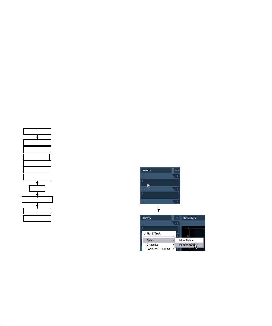
1. Bring up the Channel Settings window or the Inserts
section in the Inspector.
In the Channel Settings window, the inserts are located to the far left.
2. Pull down the effect type pop-up for one of the insert
slots, and select an effect.
EQ
Volume (fader)
Insert effect 7
Insert effect 8
As you can see, the last two insert slots (for any channel)
are post-EQ and post-fader. Post-fader slots are best
suited for insert effects where you don’t want the level to be
changed after the effect, such as dithering and maximizers
– both typically used as insert effects for output busses.
Ö Applying insert effects on many channels uses up a lot
of CPU power!
It might often be more efficient to use send effects or use insert effects
on Group tracks, especially if you want to use the same type of effect on
several channels. Remember that you can use the VST Performance window to keep an eye on the CPU load.
Audio effects
The effect is loaded and automatically activated and its
control panel appears. You can hide or show the control
panel by clicking the “e” button for the insert slot.
7
Page 8
• If the effect has a Dry/Wet Mix parameter you can use
this to adjust the balance between the dry signal and the
effect signal.
See “Making settings for the effects” on page 12 for details about editing
effects.
• When one or several insert effects are activated for a
channel, the insert effects buttons light up in blue in the
mixer, the Inspector and the Track list. Click the button for
a channel to bypass (disable) all its inserts.
When the inserts are bypassed, the buttons are yellow. Click the button
again to enable the inserts. Note that the bypass button is also available
in the Inspector and the Channel settings window for the audio track.
• To remove an effect, pull down the effect type pop-up
menu and select “No Effect”.
You should do this for all effects that you don’t intend to use, to minimize
unnecessary CPU load.
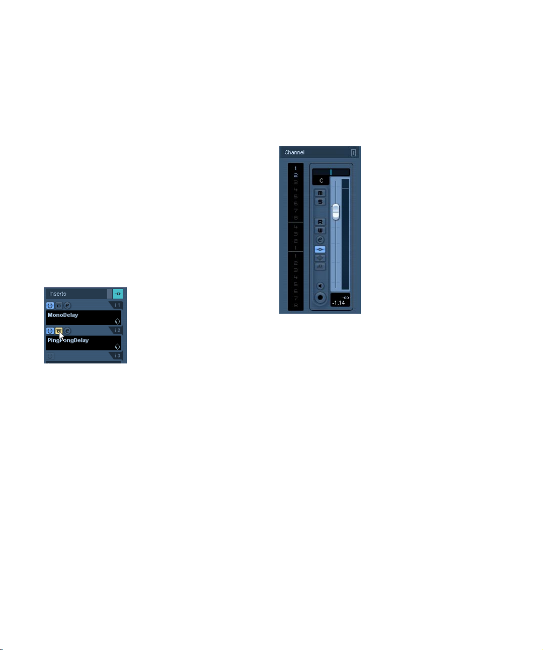
• When you have several insert effects for a channel, you
can bypass separate effects by clicking the bypass button
of the respective slot.
When an effect is bypassed, the button is yellow.
The “PingPongDelay” insert effect slot is bypassed.
Insert effects in the channel overview
If the “Channel” section is selected in the Inspector, you will
get an overview of which EQ modules, insert effects and effect sends are activated for the channel.
You can activate or deactivate individual insert effect slots
by clicking the corresponding number (in the upper part of
the overview).
The channel overview in the Inspector.
About adding insert effects to busses
As already stated, output busses have eight insert slots,
just like regular audio channels. The procedures for adding insert effects are the same (except you cannot use the
Inspector here).
• Insert effects added to an output bus will affect all audio
routed to that bus, like a “master insert effect”.
Typically you would add compressors, limiters, EQ or other plug-ins to
tailor the dynamics and sound of the final mix.
8
Audio effects
Page 9
Using group channels for insert effects
Like all other channels, group channels can have up to
eight insert effects. This is useful if you have several audio
tracks that you want to process through the same effect
(e.g. different vocal tracks that all should be processed by
the same compressor). Another special use for group
channels and effects is the following:
If you have a mono audio track and want to process this
through a stereo insert effect (e.g. a stereo chorus or an
auto panner device), you cannot just insert the effect as
usual. This is because the audio track is in mono – the
output of the insert effect will then be in mono as well, and
the stereo information from the effect will be lost.
One solution would be to route a send from the mono
track to a stereo FX channel track, set the send to pre
fader mode and lower the fader completely for the mono
audio track. However, this makes mixing the track cumbersome, since you cannot use the fader.
Here’s another solution:
1. Create a group channel track in stereo and route it to
the desired output bus.
2. Add the desired effect to the group channel as an insert effect.
3. Route the mono audio track to the group channel.
Now the signal from the mono audio track is sent directly
to the group, where it passes through the insert effect, in
stereo.
Send effects
Background
Send effects are handled through FX channel tracks.
These are special tracks that each can contain up to eight
insert effects. The signal path is as follows:
• By routing an effect send from an audio track to an FX
channel track, the audio is sent to the FX channel and
through its insert effect(s).
Each audio channel has eight sends, which can be routed to different FX
channels. You control the amount of signal sent to the FX channel by adjusting the effect send level.
• If you have added several effects to the FX channel, the
signal passes through the effects in series, from the top
(the first slot) downward.
This allows for “custom” send effect configurations – you could e.g. have
a chorus followed by a reverb followed by an EQ and so on.
• The FX channel track has its own channel strip in the
mixer, the effect return channel.
Here you can adjust the effect return level and balance.
• Each FX channel track has an automation subtrack, for
automating various effect parameters.
See the chapter “Automation” in the Operation Manual for more information.
Setting up send effects
Adding an FX channel track
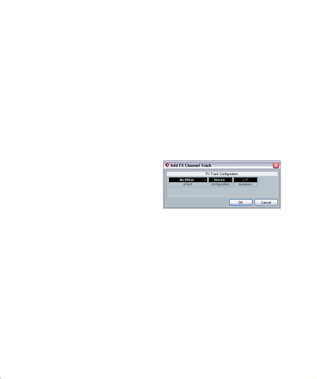
1. Pull down the Project menu and select “FX Channel”
from the “Add Track” submenu.
A dialog appears.
2. Select a channel configuration for the FX channel
track.
Normally, stereo is a good choice since most effect plug-ins have stereo
outputs.
3. Select an effect for the FX channel track.
This is not strictly necessary at this point – you can leave the Plug-in
pop-up menu set to “No Effect” and add effects to the FX channel later if
you like.
4. Click OK.
An FX channel track is added to the Track list, and the selected effect, if
any, is loaded into the first insert effect slot for the FX channel (in that
case, the lit Inserts tab for the FX channel track in the Inspector indicates
that an effect has been assigned and automatically activated).
9
Audio effects
Page 10
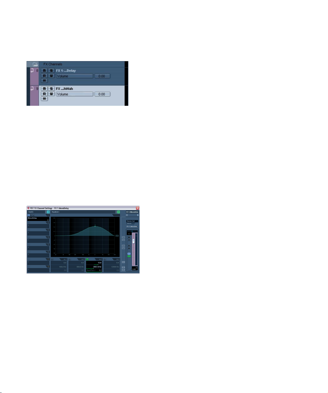
• All FX channel tracks you create will appear in a kind of
“folder” in the Track list.
This makes it easy to manage and keep track of all your FX channel tracks,
and also allows you to save screen space by folding the FX Channel folder.
FX channel tracks are automatically named “FX 1”, “FX 2” etc., but you
can rename them if you wish. Just double click the name of an FX channel track in either the Track list or the Inspector and type in a new name.
Adding and setting up effects
As mentioned above, you can add a single insert effect
when you create the FX channel track if you like. To add
and set up effects after the FX channel track is created,
you can either use the Inspector for the track (click the Inserts tab) or the FX Channel Settings window:
1. Click the Edit (“e”) button for the FX channel track (in
the Track list, mixer or Inspector).
The FX Channel Settings window appears, similar to a regular Channel
Settings window.
4. When you add an effect, its control panel will automatically appear. Typically you should set the Wet/Dry Mix
control to all “wet”.
This is because you control the balance between wet and dry signal with
the effect sends. For more information about making settings in the effect
control panels, see “Making settings for the effects” on page 12.
• You can add up to eight insert effects for an FX channel.
Note that the signal will pass through all the effects in series. It is not
possible to adjust the effect send and return levels separately for each
effect – this is done for the FX channel as a whole. If what you want is
several separate send effects (where you can control their send and return levels independently) you should instead add more FX channel
tracks – one for each effect.
• To remove an insert effect from a slot, click the slot and
select “No Effect” from the pop-up menu.
You should do this for all effects that you don’t intend to use, to minimize
unnecessary CPU load.
• You can also bypass individual effects (or all effects) by
clicking the corresponding Bypass Inserts button(s) for
the FX channel track.
See “Routing an audio channel or bus through insert effects” on page 7.
• You can also adjust level, pan and EQ for the effect return in this window.
Ö Remember that effects rely heavily on the CPU power
in your computer.
The more activated effect units, the more computer power will be used
for effects.
To the left in the window is the Inserts section with eight effect slots.
2. Make sure the FX channel is routed to the correct output bus.
This is done with the output routing pop-up menu at the top of the fader
section (also available in the Inspector).
3. To add an insert effect in an empty slot (or replace the
current effect in a slot), click on the slot and select an effect from the pop-up menu.
This works just like when selecting insert effects for a regular audio
channel.
Audio effects
Setting up the sends
The next step is to set up and route a send for an audio
channel to the FX channel. This can be done in the Channel Settings window or in the Inspector for the audio track.
The example below shows the Channel Settings window,
but the procedure is similar for both sections:
1. Click the “e” button for an audio channel to bring up its
Channel Settings window.
In the Inspector you would click the Sends tab.
In the channel settings window, the send section is located to the left of the channel strip. Each of the eight
sends has the following controls and options:
• A send on/off switch
• A send level slider
• A pre/post fader switch
•An Edit button
10
Page 11
Note that the last three items are not shown until the Send
is activated and an effect has been loaded.
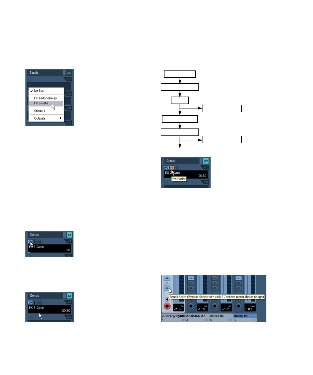
2. Pull down the routing pop-up menu for a send by
clicking in the empty slot, and select the desired routing
destination.
6. If you want the signal to be sent to the FX channel before the audio channel’s volume fader in the mixer, click on
the Pre Fader button for the send so that it lights up.
Normally you want the effect send to be proportional to the channel volume (post fader send). The picture below shows where the sends are
“tapped” from the signal in pre and post fader mode:
Input gain
Insert effects 1-6
EQ
Pre-fader sends
Volume (fader)
• If the first item on this menu, “No Bus” is selected, the send
isn’t routed anywhere.
• Items called “FX 1”, “FX 2” etc. correspond to existing FX
tracks. If you have renamed an FX track (see “Adding an FX
channel track” on page 9) that name will appear on this menu
instead of the default.
• The menu also allows for routing a send directly to output busses, separate output bus channels or Group channels.
3. In this case, select an FX channel track from the pop-
up menu.
Now the send is routed to the FX channel.
4. Click the power button for the effect send so that it
lights up in blue.
This activates the send.
5. Click and drag the send level slider to a moderate
value.
The send level determines how much of the signal from the audio channel is routed to the FX channel via the send.
Insert effects 7-8
Post-fader sends
A send set to pre fader mode.
Ö You can choose whether a send in pre fader mode
should be affected by the channel’s Mute button or not.
This is done with the option “Mute Pre-Send when Mute” in the Preferences (VST page).
• When one or several sends are activated for a channel,
the Send Effects buttons light up in blue in the mixer and
the Track list. Click the button for a channel to bypass
(disable) all its effect sends.
When the sends are bypassed, the button is yellow. Click the button
again to enable the sends. Note that this button is also available in the Inspector and the Channel settings window.
Setting the Send level.
Click this button to bypass the sends.
11
Audio effects
Page 12
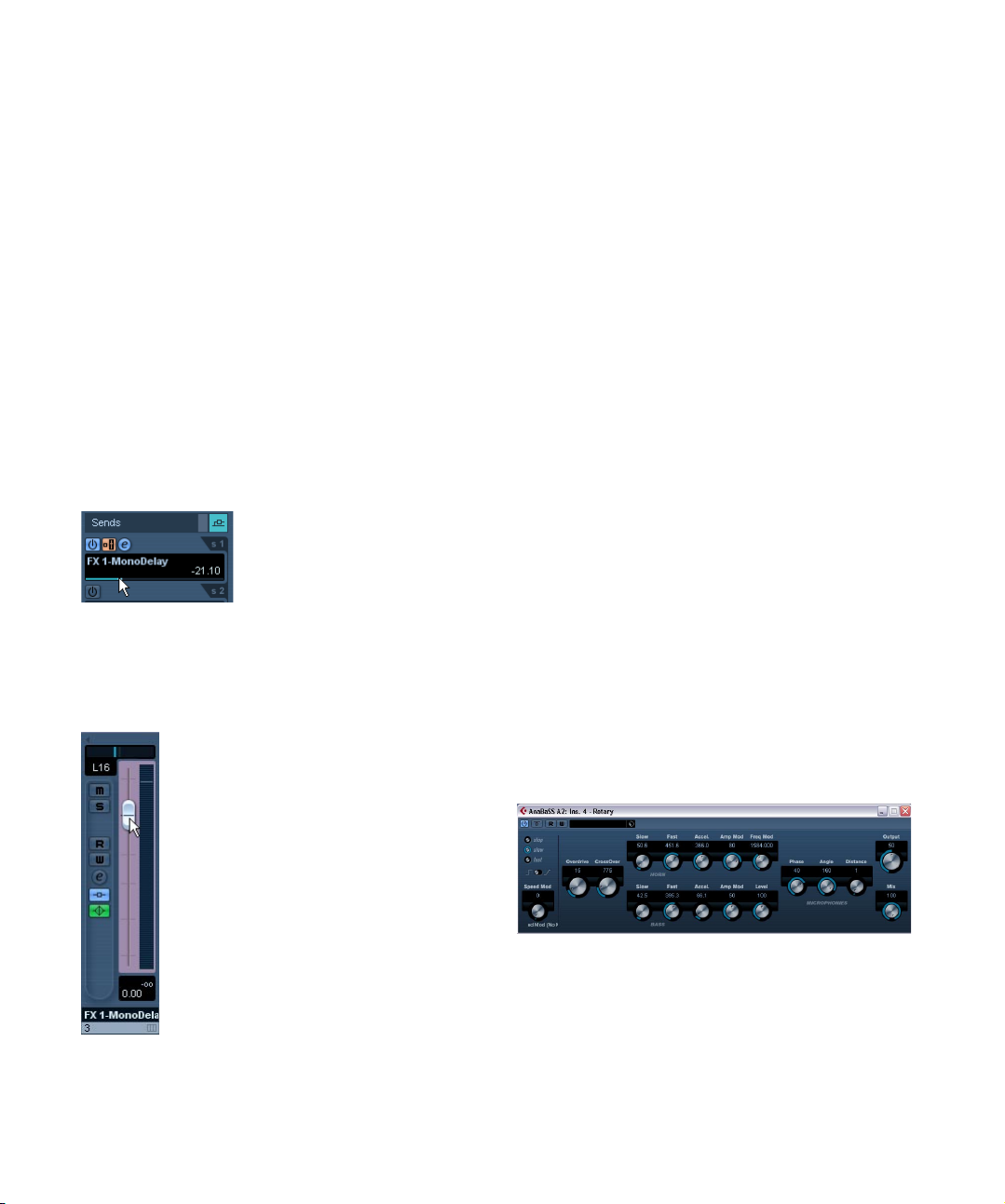
• You can also bypass individual sends in the channel
overview.
See “Insert effects in the channel overview” on page 8.
• Alternatively, in the same manner you can bypass the
send effects by clicking the “Bypass Inserts” button for
the FX channel.
The difference is that this bypasses the actual send effects which may be
used by several different channels. Bypassing a send affects that send
and that channel only. If you bypass the insert effect the original sound
will be passed through. This may lead to unwanted side effects (higher
volume). To deactivate all effects, use the mute button in the FX channel.
Setting effect levels
After you have set up the sends as described in the previous sections, the following is now possible:
• You can use the send level slider in the Channel Set-
tings or the Inspector to set the send level.
By adjusting the send level you control the amount of signal sent from the
audio channel to the FX channel.
Setting the effect send level.
• In the mixer, you can use the level fader for the FX chan-
nel to set the effect return level.
By adjusting the return level you control the amount of the signal sent
from the FX channel to the output bus.
FX channels and the Solo Defeat function
When mixing, you might sometimes want to solo specific
audio channels, and listen only to these while other channels are muted. However, this will mute all FX channels as
well. If the soloed audio channels have sends routed to FX
channels, this means you won’t hear the send effects for
the channels.
To remedy this, you can use the Solo Defeat function for
the FX channel:
1. First press [Alt]/[Option] and click on the Solo button
for the FX channel.
This activates the Solo Defeat function for the FX channel. In this mode,
the FX channel will not be muted if you solo another channel in the mixer.
2. You can now solo any of the audio channels without
having the effect return (the FX channel) muted.
3. To turn off Solo Defeat for the FX channel, [Alt]/[Option]-click the Solo button for the FX channel again.
Making settings for the effects
Editing effects
All inserts and sends have an Edit (“e”) button. Clicking
this opens the selected effect’s control panel in which you
can make parameter settings.
The contents, design and layout of the control panel depends on the selected effect. However, all effect control
panels have a power button, a Bypass button, Read/Write
automation buttons (for automating effect parameter
changes (see the chapter “Automation” in the Operation
Manual), a Preset selection pop-up menu and a Preset
Management pop-up menu for saving or loading programs.
Setting the effect return level.
The Rotary effect control panel.
• Please note that all effects can be edited using a simplified control panel (horizontal sliders only, no graphics). To
edit effects using this “basic” control panel instead, press
[Ctrl]/[Command]+[Alt]/[Option]+[Shift] and click on the
Edit button for the effect send or slot.
12
Audio effects
Page 13
Making settings
Effect control panels may have any combination of knobs,
sliders, buttons and graphic curves.
Ö For specifics about the included effects and their parameters, please refer to the chapter “The included effect
plug-ins” on page 18.
If you edit the parameters for an effect, these settings are
saved automatically in the project. If you want to save the
current settings, the following points apply:
• The basis for the current settings may have been a preset effect program, in which case there is a name in the preset field.
• The basis for the current settings may have been a default setting program location in which case “Default” is displayed in
the preset field.
In both cases, if you have changed any effect parameter
settings, these are automatically saved when you save the
program. How to select and save effect presets is described below.
Automating effect parameters
Effects parameters can be automated – see the chapter
“Automation” in the Operation Manual.
Effect presets
Cubase AI comes with a number of categorized VST presets that you can use straight out of the box. VST presets
are stored parameter settings for a specific effect.
Selecting effect presets
Most VST effect plug-ins come with a number of useful
presets for instant selection. The Preset browser can either be accessed from the control panel for the effect,
from the Channel Settings window, or from the Inspector.
To select an effect preset, proceed as follows:
1. Load an effect, either as a channel Insert or into a FX
channel, it doesn’t matter.
The effect’s control panel is automatically shown when loaded.
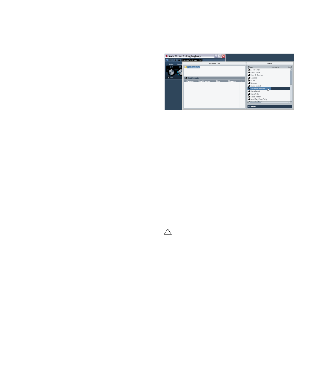
2. Click in the name field at the top of the effect’s control
panel.
This opens the Preset browser.
• The right half of the browser shows the available presets for the selected effect.
Selecting a preset loads it directly, replacing the previous preset.
• The lower left half of the Preset browser contains a section where all assigned attributes (to any preset) for the
selected effect are shown in the respective column.
If no attributes have been specified for the effect presets, the various columns will be empty. If attributes have been assigned to a preset for this
effect, you can click on the assigned attribute in the respective column
(Category, Style etc.), to filter out all presets that do not match the selected attribute(s).
• The preset handling for VST 2 plug-ins is slightly different, see “About earlier VST effect presets” on page 15.
• You can also open the Preset browser from the Inspector. Click the Inserts tab for the channel with the effect and
click in the Preset name field.
!
In the Inspector there is a dual functionality. When an
effect is loaded into a slot you can click on the Preset
name (or in the bottom half of the effect slot) to open
the Preset browser. Clicking in the upper half of the
slot will instead open the Effect selection pop-up.
• Click the VST Sound button (the cube symbol) to open
the Preset Management pop-up menu and select “Load
Preset…” from the pop-up menu that appears.
The “Load Preset” dialog opens.
13
Audio effects
Page 14

This dialog is very similar to the Preset browser, but there
is a difference in how the effect presets are loaded:
• If you use the “Load Preset” dialog, this allows you to se-
lect different presets and to audition them without actually
loading them. If you chose to cancel the operation and exit
the dialog, the preset that was selected before opening the
dialog will be reloaded exactly as it was, including any unsaved changes. See “Auditioning presets” on page 14.
• When you use the Preset browser, selecting another
preset will load it directly, replacing the previous preset.
3. When you have selected an effect preset in the list to
the left, click OK to confirm the selection in case you used
the Load Preset dialog, or simply click outside the
browser window.
Auditioning presets
A new VST 3 feature is the option to audition effects before you load them. This works as follows:
1. Load an effect as usual for the track you wish to pro-
cess.
2. Start playback.
It may be helpful to set up cycle playback of a section to make comparisons between different preset settings easier.
• Open the Load Preset dialog by clicking the VST Sound
button in the effect slot and select “Load Preset” from the
pop-up.
3. Activate “Auto Preview” below the Viewer display.
4. With playback still running, you now can step through
different presets in the list and hear the results instantly!
• If you activate “Preview” in step 3 it works similarly, but
you have to activate Preview for each selected preset to
audition the settings.
• To confirm a preset selection and to load it, click OK.
• If you click Cancel, the previously loaded preset will re-
main, including any unsaved settings.
Saving effect presets
You can save your edited effects for further use (e.g. in
other projects):
1. Click the VST Sound button to open the Load/Save
Preset pop-up.
2. Select “Save Preset…” from the pop-up.
This opens a dialog where you can save the current settings as a preset.
Presets are saved into a default folder named VST3 Presets. Within this folder, there is a folder named “Steinberg
Media Technologies” where the included presets are arranged in subfolders named after each effect.
You cannot change the default folder, but you can add further subfolders inside the individual effect preset folder.
Under Windows, the default preset folder is located in the
following location:
Boot drive/Documents and Settings/User name/Application data/VST3
Presets.
• Under Mac OS, the default preset folder is located in
the following location:
Users/Username/Library/Audio/Plug-Ins/Presets/
14
Audio effects
Page 15

3. In the File name field in the lower part of the dialog you
can enter a name for the new preset.
4. Click OK to store the preset and exit the dialog.
About earlier VST effect presets
As stated previously, you can use any VST 2.x plug-ins in
Cubase AI. For a description of how to add VST plug-ins
see “Installing and managing effect plug-ins” on page 15.
When you add a VST 2 plug-in, any previously stored presets for it will be of the old FX program/bank (.fxp/.fxb)
standard. You can import such files, but the preset handling will be slightly different. You will not immediately be
able to use the new features like the Preview function until
you have converted the old “.fxp/.fxb” presets to VST 3
presets. If you save new presets for the included VST 2
plug-ins these will automatically be saved in the new “.vstpreset” format.
• For all the plug-ins in the “Earlier VST Plug-ins” cate-
gory (or any other VST 2 plug-ins you may have installed),
you can import presets of the previous “.fxp/.fxb” standard
to ensure backwards compatibility.
Importing and converting FXB/FXP files
To import .fxp/.fxb files, proceed as follows:
1. Load an effect from the “Earlier VST Plug-ins” folder
(or any VST 2 effect you may have installed), and click on
the VST Sound button to open the Preset Management
pop-up menu.
4. After importing, you can convert the current program
list to VST Presets by selecting “Convert Program List to
VST Presets” from the Preset Management pop-up.
After converting, the presets will be available in the Preset browser. The
new converted presets will be stored in the VST3 Preset folder.
Installing and managing effect plugins
Cubase AI supports two plug-in formats; the VST 2 format
(extension “.dll”) and the VST 3 format (extension “.vst3”).
The formats are handled differently when it comes to installation and organizing.
Installing additional VST plug-ins
Installing VST 3 plug-ins under Mac OS X
To install a VST 3.x plug-in under Mac OS X, quit Cubase
AI and drag the plug-in file to one of the following folders:
• /Library/Audio/Plug-Ins/VST3/
This is only possible if you are the system administrator. Plug-ins installed in this folder will be available to all users, for all programs that
support them.
• Users/Username/Library/Audio/Plug-Ins/VST3/
“Username” above is the name you use to log on to the computer (the
easiest way to open this folder is to go to your “Home” folder and use the
path /Library/Audio/Plug-Ins/VST/ from there). Plug-ins installed in this
folder are only available to you.
When you launch Cubase AI again, the new effects will appear on the effect pop-up menus. In the VST 3 protocol, the
effect category, sub-folder structure etc. is built-in and cannot be changed. The effect(s) will show up in the assigned
category folder(s) on the Effect pop-up menu.
2. Select “Import FXB/FXP…” from the pop-up.
This menu item is only available for VST 2 plug-ins.
3. In the file dialog that opens, locate the file and click
Open.
If you loaded a Bank, it will replace the current set of all effect programs.
If you loaded a single effect, it will replace the currently selected effect
program only.
Audio effects
Installing VST 2.x plug-ins under Mac OS X
!
Plug-ins in Mac OS 9.X format cannot be used.
To install a VST 2.x plug-in under Mac OS X, quit Cubase
AI and drag the plug-in file to one of the following folders:
• /Library/Audio/Plug-Ins/VST/
This is only possible if you are the system administrator. Plug-ins installed in this folder will be available to all users, for all programs that
support them.
15
Page 16

• Username/Library/Audio/Plug-Ins/VST/
“Username” above is the name you use to log on to the computer (the
easiest way to open this folder is to go to your “Home” folder and use the
path /Library/Audio/Plug-Ins/VST/ from there). Plug-ins installed in this
folder are only available to you.
When you launch Cubase AI again, the new effects will
appear on the effect pop-up menus.
Ö An effect plug-in may also come with its own installation application, in which case you should use this.
Generally, always read the documentation or readme files before installing new plug-ins.
Installing VST 3 plug-ins under Windows
Under Windows, VST 3 plug-ins are installed simply by
dragging the files (extension “.vst3”) into the vst3 folder in
the Cubase AI application folder. When you launch Cubase AI again, the new effects will appear on the Effect
pop-up menus. In the VST 3 protocol, the effect category,
sub-folder structure etc. is built-in and cannot be changed.
The installed new effect(s) will show up in the assigned
category folder(s) on the Effect pop-up menu.
Installing VST 2 plug-ins under Windows
Under Windows, VST 2.x plug-ins are usually installed
simply by dragging the files (with the extension “.dll”) into
the Vstplugins folder in the Cubase AI application folder,
or into the Shared VST Plug-in folder – see below. When
you launch Cubase AI again, the new effects will appear
on the Effect pop-up menus.
Ö If the effect plug-in comes with its own installation application, you should use this.
Generally, always read the documentation before installing new plug-ins.
Organizing VST 2 plug-ins
If you have a large number of VST 2 plug-ins, having them
all on a single pop-up menu in the program may become
unmanageable. For this reason, the VST 2 plug-ins installed with Cubase AI are placed in appropriate subfolders according to the effect type.
• Under Windows, you can rearrange this by moving,
adding or renaming subfolders within the Vstplugins folder
if you like.
When you launch the program and pull down an Effects pop-up menu,
the subfolders will be represented by hierarchical submenus, each listing
the plug-ins in the corresponding subfolder.
• Under Mac OS X, you cannot change the hierarchic arrangement of the “built-in” VST plug-ins.
You can however arrange any additional plug-ins you have installed (in the
/Library/Audio/Plug-Ins/VST/ folders, see above) by placing them in subfolders. In the program, the subfolders will be represented by hierarchical
submenus, each listing the plug-ins in the corresponding subfolder.
The Plug-in Information window
On the Devices menu, you will find an item called “Plug-in
Information”. Selecting this opens a dialog listing all the
available VST compatible plug-ins in your system (including VST Instruments).
Managing and selecting VST plug-ins
To see which VST plug-ins are available in your system,
click the “VST PlugIns” tab at the top of the window.
• To enable a plug-in (make it available for selection),
click in the left column.
Only the enabled plug-ins (shown with a check mark in the left column)
will appear on the effect menus.
• The second column indicates how many instances of
the plug-in are currently used in Cubase AI.
Clicking in this column for a plug-in which is already in use produces a
pop-up showing exactly where each use occurs – select an instance to
open the control panel for the plug-in.
Ö A plug-in may be in use even if it isn’t enabled in the
left column.
You might for example have opened a project containing effects that currently are disabled on the menu. The left column purely determines
whether or not the plug-in will be visible on the effect menus.
• All columns can be resized by using the divider in the
column header.
16
Audio effects
Page 17

The other columns show the following information about
each plug-in:
Column Description
Name The name of the plug-in.
Vendor The manufacturer of the plug-in.
File This shows the complete name of the plug-in (with exten-
Path The path and name of the folder in which the plug-in file
Category This indicates the category of each plug-in (such as VST
Version Shows the current version of the plug-in.
SDK Shows with which version of the VST protocol a plug-in
Latency This shows the delay (in samples) that will be introduced
I/O This column shows the number of inputs and outputs for
sion).
is located.
Instruments etc.).
is compatible.
if the effect is used as an Insert. This is automatically
compensated for by Cubase AI.
each plug-in.
Update button
Pressing this button will make Cubase AI re-scan the designated VST folders for updated information about the
plug-ins.
VST 2.x Plug-in Paths button
This opens a dialog where you can see the current paths
to where VST 2.x plug-ins are located. You can freely
Add/Remove folder locations by using the corresponding
buttons. If you click Add a file dialog is opened, where you
can select a folder location.
About the Shared Plug-ins Folder (Windows and VST 2.x
only)
You can designate a “shared” VST 2.x plugins folder. This
will allow VST 2.x plug-in to be used by other programs
that support this standard.
You designate a shared folder by selecting a folder in the
list and clicking the “Set As Shared Folder” button in the
VST 2.x Plug-in Paths dialog.
Audio effects
17
Page 18

2
The included effect plug-ins
Page 19

Introduction
This chapter contains descriptions of the included plug-in
effects and their parameters.
In Cubase AI, the plug-in effects are arranged in a number
of different categories. This chapter is arranged in the
same fashion, with the plug-ins listed in separate sections
for each effect category.
PingPongDelay
Delay plug-ins
This section contains descriptions of the plug-ins in the
“Delay” category.
MonoDelay
This is a mono delay effect that can either be tempobased or use freely specified delay time settings.
The parameters are as follows:
Parameter Description
Delay This is where you specify the base note value for the de-
Tempo sync on/
off
Feedback This sets the number of repeats for the delay.
Filter Lo This filter affects the feedback loop of the effect signal
Filter Hi This filter affects the feedback loop of the effect signal
Mix Sets the level balance between the dry signal and the ef-
lay if tempo sync is on (1/1–1/32, straight, triplet or dotted). If tempo sync is off, it sets the delay time in
milliseconds.
The button below the Delay Time knob is used to turn
tempo sync on or off. If set to off the delay time can be
set freely with the Delay Time knob, without sync to
tempo.
and allows you to roll off low frequencies from 10Hz up to
800Hz. The button below the knob activates/deactivates
the filter.
and allows you to roll off high frequencies from 20kHz
down to 1.2kHz. The button below the knob activates/
deactivates the filter.
fect. If MonoDelay is used as a send effect, this should be
set to maximum as you can control the dry/effect balance
with the send.
This is a stereo delay effect that alternates each delay repeat between the left and right channels. The effect can
either be tempo-based or use freely specified delay time
settings.
The parameters are as follows:
Parameter Description
Delay This is where you specify the base note value for the de-
Tempo sync on/
off
Feedback This sets the number of repeats for the delay.
Filter Lo This filter affects the feedback loop and allows you to roll
Filter Hi This filter affects the feedback loop and allows you to roll
Spatial This parameter sets the stereo width for the left/right re-
Mix Sets the level balance between the dry signal and the ef-
lay if tempo sync is on (1/1–1/32, straight, triplet or dotted). If tempo sync is off, it sets the delay time in
milliseconds.
The button below the Delay Time knob is used to turn
tempo sync on or off. If set to off the delay time can be
set freely with the Delay Time knob, without sync to
tempo.
off low frequencies up to 800Hz. The button below the
knob activates/deactivates the filter.
off high frequencies from 20kHz down to 1.2kHz. The
button below the knob activates/deactivates the filter.
peats. Turn clockwise for a more pronounced stereo
“ping-pong” effect.
fect. If PingPongDelay is used as a send effect, this
should be set to maximum as you can control the dry/effect balance with the send.
19
The included effect plug-ins
Page 20

Dynamics plug-ins
This section contains descriptions of the plug-ins in the
“Dynamics” category.
Gate
Parameter Description
Hold
(0 – 2000 ms)
Release
(10 – 1000 ms
or “Auto”)
Analysis
(0 – 100)
(Pure Peak to
Pure RMS
Live mode
(On/Off)
This determines how long the gate stays open after the signal drops below the threshold level.
This parameter sets the amount of time it takes for the gate
to close (after the set hold time). If the “Auto” button is activated, Gate will find an optimal release setting, depending
on the audio program material.
This parameter determines whether the input signal is analyzed according to Peak or RMS values (or a mixture of
both). A value of 0 is pure Peak and 100 pure RMS. RMS
mode operates using the average power of the audio signal
as a basis, whereas Peak mode operates more on peak levels. As a general guideline, RMS mode works better on material with few transients such as vocals, and Peak mode
better for percussive material, with a lot of transient peaks.
When activated, Live mode disengages the “look ahead”
feature of the Gate. Look ahead does produce more accurate processing but will add a certain amount of latency as
a trade-off. When Live mode is activated, there is no latency, which might be better for “live” processing.
Gating, or noise gating, silences audio signals below a
certain set threshold level. As soon as the signal level exceeds the set threshold, the gate opens to let the signal
through.
The available parameters are as follows:
Parameter Description
Threshold
(-60 – 0dB)
Filter buttons When the Side Chain button (see below) is activated, you
Side chain
(Off/On)
Center
(50Hz –
20000Hz)
Q-Factor
(0.01 –
10000)
Monitor
(Off/On)
Attack
(0.1 – 1000
ms)
This setting determines the level where Gate is activated.
Signal levels above the set threshold trigger the gate to
open, and signal levels below the set threshold will close
the gate.
can use these buttons to set the filter type to either Low
Pass, Band Pass or High Pass.
This button (below the Center knob) activates the filter. The
input signal can then be shaped according to set Center
and Q-Factor parameters which may be useful in tailoring
how the Gate operates.
Sets the center frequency of the filter.
Sets the Resonance of the filter.
Allows you to monitor the filtered signal.
This parameter sets the time it takes for the gate to open
after being triggered. If the Live button (see below) is deactivated, it will ensure that the gate will already be open
when a signal above the threshold level is played back.
Gate manages this by “looking ahead” in the audio material, checking for signals loud enough to pass the gate.
Limiter
Limiter is designed to ensure that the output level never
exceeds a certain set output level, to avoid clipping in following devices. Limiter can adjust and optimize the Release parameter automatically according to the audio
material, or it can be set manually. Limiter also features
separate meters for the input, output and the amount of
limiting (middle meters).
The available parameters are the following:
Parameter Description
Input
(-24 – +24dB)
Output
(-24 – +6 dB)
Allows you to adjust the input gain.
This setting determines the maximum output level.
20
The included effect plug-ins
Page 21

Parameter Description
Release
(0.1 – 1000ms
or Auto mode)
This parameter sets the amount of time it takes for the gain
to return to its original level. If the “Auto” button is activated, Limiter will automatically find an optimal release setting that varies depending on the audio material.
VSTDynamics
Parameter Description
Center
(50 – 22000Hz)
Q-Factor
(0.001 – 10000)
Monitor
(Off/On)
Attack
(0,1 – 100 ms)
Hold
(0 – 2000 ms)
Release
(10 – 1000 ms
or “Auto”)
This sets the center frequency of the filter.
This sets the resonance or width of the filter.
Allows you to monitor the filtered signal.
This parameter sets the time it takes for the gate to open
after being triggered.
This determines how long the gate stays open after the
signal drops below the threshold level.
This parameter sets the amount of time it takes for the
gate to close (after the set hold time). If the “Auto” button
is activated, Gate will find an optimal release setting, depending on the audio program material.
Gate
Compressor
Limiter
Routing selector
VSTDynamics is an advanced dynamics processor. It
combines three separate processors: Gate, Compressor
and Limiter, covering a variety of dynamic processing
functions. The window is divided into three sections, containing controls and meters for each processor.
Activating the individual processors
You activate the individual processors using the buttons
at the bottom of the plug-in panel.
The Gate section
Gating, or noise gating, is a method of dynamic processing that silences audio signals below a certain set threshold level. As soon as the signal level exceeds the set
threshold, the gate opens to let the signal through. The
Gate trigger input can also be filtered using an internal
side-chain.
The available parameters are as follows:
Parameter Description
Threshold
(-60 – 0dB)
Side Chain
(On/Off)
LP (Lowpass),
BP (Bandpass),
HP (Highpass)
This setting determines the level where Gate is activated.
Signal levels above the set threshold trigger the gate to
open, and signal levels below the set threshold will close
the gate.
This button activates the internal side-chain filter. This
lets you filter out parts of the signal that might otherwise
trigger the gate in places you don’t want it to, or to boost
frequencies you wish to accentuate, allowing for more
control over the gate function.
These buttons set the basic filter mode.
The Compressor section
Compressor reduces the dynamic range of the audio,
making softer sounds louder or louder sounds softer, or
both. Compressor functions like a standard compressor
with separate controls for threshold, ratio, attack, release
and make-up gain parameters. Compressor features a
separate display that graphically illustrates the compressor curve shaped according to the Threshold, Ratio and
MakeUp Gain parameter settings. Compressor also features a Gain Reduction meter that shows the amount of
gain reduction in dB, and a program dependent Auto feature for the Release parameter.
The available parameters work as follows:
Parameter Description
Threshold
(-60 – 0dB)
Ratio
(1:1 – 8:1)
Make-Up
(0 – 24dB)
Attack
(0.1 – 100 ms)
Release
(10 – 1000ms
or “Auto”)
This setting determines the level where Compressor “kicks
in”. Signal levels above the set threshold are affected, but
signal levels below are not processed.
Ratio determines the amount of gain reduction applied to
signals over the set threshold. A ratio of 3:1 means that for
every 3 dB the input level increases, the output level will increase by only 1 dB.
This parameter is used to compensate for output gain loss,
caused by compression. When Auto is on, gain loss will be
compensated automatically.
This determines how fast Compressor will respond to signals above the set threshold. If the attack time is long, more
of the early part of the signal (attack) will pass through unprocessed.
Sets the amount of time it takes for the gain to return to its
original level when the signal drops below the Threshold
level. If the “Auto” button is activated, Compressor will automatically find an optimal release setting that varies depending on the audio material.
21
The included effect plug-ins
Page 22

Parameter Description
Graphic
display
Use the graphic display to graphically set the Threshold or
the Ratio value.
The Limiter section
Limiter is designed to ensure that the output level never
exceeds a certain set output level, to avoid clipping in following devices. Conventional limiters usually require very
accurate setting up of the attack and release parameters,
to prevent the output level from going beyond the set
threshold level. Limiter adjusts and optimizes these parameters automatically, according to the audio material.
You can also adjust the Release parameter manually.
The available parameters are the following:
Parameter Description
Output
(-24 – +6 dB)
Soft Clip
(On/Off)
Release
(10 – 1000ms
or “Auto”)
This setting determines the maximum output level. Signal
levels above the set threshold are affected, but signal levels
below are left unaffected.
Soft Clip acts differently compared to the limiter. When the
signal level exceeds -6dB, SoftClip starts limiting (or clipping) the signal “softly”, at the same time generating harmonics which add a warm, tubelike characteristic to the
audio material.
This parameter sets the amount of time it takes for the gain
to return to its original level when the signal drops below
the threshold level. If the “Auto” button is activated, Limiter
will automatically find an optimal release setting that varies
depending on the audio material.
The Module Configuration button
Filter plug-ins
In this section, the Filter plug-in WahWah will be described.
WahWah
WahWah is a variable slope bandpass filter that can be
auto-controlled via MIDI modeling the well-known analog
pedal effect (see below). You can independently specify
the frequency, width and the gain for the Lo and Hi Pedal
positions. The crossover point between the Lo and Hi
Pedal positions is at 50.
The parameters are as follows:
Parameter Description
Pedal This controls the filter frequency sweep.
Freq Lo/Hi Sets the frequency of the filter for the Lo and Hi Pedal
Width Lo/Hi Sets the width (resonance) of the filter for the Lo and Hi
Gain Lo/Hi Sets the gain of the filter for the Lo and Hi Pedal posi-
Slope Specifies the slope of the filter; 6dB or 12dB.
positions.
Pedal positions.
tions.
In the bottom right corner of the plug-in panel you will find
a button with which you can set the signal flow order for
the three processors. Changing the order of the processors can produce different results, and the available options allow you to quickly compare what works best for a
given situation. Simply click the Module Configuration button to change to a different configuration. There are three
routing options:
• C-G-L (Compressor-Gate-Limit)
• G-C-L (Gate-Compressor-Limit)
• C-L-G (Compressor-Limit-Gate)
The included effect plug-ins
MIDI control
For real-time MIDI control of the Pedal parameter, MIDI
must be directed to the WahWah plug-in.
• Whenever the WahWah has been added as an insert
effect (for an audio track or an FX channel), it will be available on the Output Routing pop-up menu for MIDI tracks.
If WahWah is selected on the Output Routing menu, MIDI will be directed to the plug-in from the selected track.
22
Page 23

Modulation plug-ins
This section contains descriptions of the plug-ins in the
“Modulation” category.
Flanger
Flanger is a classic flanger effect with added stereo enhancement.
The parameters are as follows:
Parameter Description
Tempo sync on/
off
Rate If tempo sync is on, this is where you specify the base
Range Lo/Hi This sets the frequency boundaries for the flanger sweep.
Feedback This determines the character of the flanger effect.
Spatial This sets the stereo width of the effect. Turn clockwise
Mix Sets the level balance between the dry signal and the ef-
Shape This changes the shape of the modulating waveform, al-
Delay This parameter affects the frequency range of the modu-
Manual If this is activated, the flanger sweep will be static, i.e. no
Filter Lo/Hi These parameters allow you to roll off low and high fre-
The button below the Rate knob is used to switch tempo
sync on or off. The button is lit when tempo sync is on.
note value for tempo syncing the flanger sweep (1/1 to
1/32, straight, triplet or dotted).
If tempo sync is off, the sweep rate can be set freely with
the Rate knob, without sync to tempo.
Higher settings produce a more “metallic” sounding
sweep.
for a wider stereo effect.
fect. If the Flanger is used as a send effect, this should be
set to maximum as you can control the dry/effect balance
with the send.
tering the character of the flanger sweep.
lation sweep, by adjusting the initial delay time.
modulation. You can instead change the sweep position
manually by turning this knob.
quencies of the effect signal, respectively.
Phaser
Phaser produces the well-known “swooshing” phasing effect with additional stereo enhancement.
The parameters are as follows:
Parameter Description
Tempo sync on/
off
Rate If tempo sync is on, this is where you specify the base
Width The width of the modulation effect between higher and
Feedback This determines the character of the phaser effect.
Spatial When using multi-channel audio, Spatial creates a 3-di-
Mix Sets the level balance between the dry signal and the ef-
Manual If this is activated, the phaser sweep will be static, i.e. no
Filter Lo/Hi These parameters allow you to roll off low and high fre-
The button below the Rate knob is used to switch tempo
sync on or off. The button is lit when tempo sync is on.
note value for tempo syncing the phaser sweep (1/1 to
1/32, straight, triplet or dotted).
If tempo sync is off, the sweep rate can be set freely with
the Rate knob, without sync to tempo.
lower frequencies.
Higher settings produce a more pronounced effect.
mensional impression by delaying modulation in each
channel.
fect. If the Phaser is used as a send effect, this should be
set to maximum as you can control the dry/effect balance
with the send.
modulation. You can instead change the sweep position
manually by turning this knob.
quencies of the effect signal, respectively.
23
The included effect plug-ins
Page 24

Rotary
The Rotary plug-in simulates the classic effect of a rotary
speaker. A rotary speaker cabinet features variable speed
rotating speakers to produce a swirling chorus effect,
commonly used with organs. Rotary features all the parameters associated with the real thing.
The parameters are as follows:
Parameter Description
Speed
(Stop/Slow/Fast
Mode Selects whether the Slow/Fast setting is a switch or a
Speed Mod Selects the Rotary speed from 0 (Stop) to 100 (Fast).
Overdrive Applies a soft overdrive or distortion.
Crossover Freq. Sets the crossover frequency (200–3000Hz) between
Slow Fine adjustment of the high rotor Slow speed.
Accel. Fine adjustment of the high rotor acceleration time.
Fast Fine adjustment of the high rotor Fast speed.
Amp Mod High rotor amplitude modulation.
Freq Mod High rotor frequency modulation.
Slow Fine adjustment of the low rotor Slow speed.
Fast Fine adjustment of the low rotor Fast speed.
Accel Fine adjustment of the low rotor acceleration time.
Amp Mod. Adjusts amplitude modulation depth.
Level Adjusts overall bass level.
Phase Adjusts the amount of phasing in the sound of the high
Angle Sets the simulated microphone angle. 0 = mono, 180 =
Distance Sets the simulated microphone distance from the
Output Adjusts the overall output level.
Mix Adjusts the mix between dry and processed signals.
This controls the speed of the Rotary in three steps.
variable control. When switch mode is selected and Pitch
Bend is the controller, the speed will switch with an up or
down flick of the bender. Other controllers switch at 64.
the low and high frequency loudspeakers.
rotor.
one mic on each side.
speaker in inches.
Directing MIDI to the Rotary
For real-time MIDI control of the Speed parameter, MIDI
must be directed to the Rotary.
• Whenever the Rotary has been added as an insert effect (for an audio track or an FX channel), it will be available on the Output Routing pop-up menu for MIDI tracks.
If Rotary is selected on the “out:” menu, MIDI will be directed to the plugin from the selected track.
Tremolo
Tremolo produces amplitude (volume) modulation.
Parameters are as follows:
Parameter Description
Tempo sync on/
off
Rate If tempo sync is on, this is where you specify the base
Depth This governs the depth of the amplitude modulation.
Spatial This will add a stereo effect to the modulation.
Output Adjusts the output volume.
The button below the Rate knob is used to switch tempo
sync on or off. The button is lit when tempo sync is on.
note value for tempo-syncing the effect (1/1 to 1/32,
straight, triplet or dotted).
If tempo sync is off, the modulation speed can be set
freely with the Rate knob, without sync to tempo.
24
The included effect plug-ins
Page 25

Vibrato
The Vibrato plug-in produces pitch modulation.
Parameter Description
Tempo sync on/
off
Rate If tempo sync is on, this is where you specify the base
Depth This governs the depth of the pitch modulation.
Spatial This will add a stereo effect to the modulation.
The button below the Rate knob is used to switch tempo
sync on or off. The button is lit when tempo sync is on.
note value for tempo-syncing the effect (1/1 to 1/32,
straight, triplet or dotted).
If tempo sync is off, the modulation speed can be set
freely with the Rate knob, without sync to tempo.
Other plug-ins
This section contains descriptions of the plug-ins in the
“Others” category.
Octaver
Parameter Description
Octave 1 This adjust the level of the generated signal one octave
Octave 2 This adjust the level of the generated signal two octaves
below the original pitch. Set to 0 means the voice is
muted.
below the original pitch. Set to 0 means the voice is
muted.
Tuner
This is a guitar tuner. Simply connect a guitar or other instrument to an audio input and select the Tuner as an insert effect (make sure you deactivate any other effect that
alters pitch, like chorus or vibrato). When the instrument is
connected, proceed as follows:
• Play a note.
The key is shown in the middle of the display. In addition, the frequency in
Hz is shown in the bottom left corner and the octave range in the bottom
right corner. If the key is wrong (e.g. if you wish to tune the E string and the
key is shown as Fb), first tune the string so that the correct key is shown.
• The two arrows indicate any deviation in pitch by their
position. If the pitch is flat, they will be positioned in the
left half of the display, if the pitch is sharp they will be in
the right half.
The deviation is also shown (in Cent) in the upper area of the display.
• Tune the instrument so that the two arrows are in the
middle.
Repeat this procedure for each string.
This plug-in can generate two additional voices that track
the pitch of the input signal one octave and two octaves
below the original pitch, respectively. Octaver is best used
with monophonic signals. The parameters are as follows:
Parameter Description
Direct This adjusts the mix of the original signal and the gener-
ated voice(s). A value of 0 means only the generated and
transposed signal is heard. By raising this value, more of
the original signal is heard.
The included effect plug-ins
25
Page 26

Spatial plug-ins
This section contains descriptions of the plug-ins in the
“Spatial” category.
MonoToStereo
This effect will turn a mono signal into a “pseudo-stereo”
signal. The plug-in must be inserted on a stereo track
playing a mono file to work.
The parameters are as follows:
Parameter Description
Width This controls the width or depth of the stereo enhance-
Delay This parameter increases the amount of differences be-
Color This parameter also generates differences between the
Mono This switches the output to mono, to check for possible
ment. Turn clockwise to increase the enhancement.
tween the left and right channels to further increase the
stereo effect.
channels to increase the stereo effect.
unwanted coloring of the sound which sometimes can
occur when creating an artificial stereo image.
StereoEnhancer
This plug-in will expand the stereo width of (stereo) audio
material. It can not be used with mono files.
The parameters are as follows:
Parameter Description
Width This controls the width or depth of the stereo enhance-
Delay This parameter increases the amount of differences be-
Color This parameter also generates differences between the
Mono This switches the output to mono, to check for possible
ment. Turn clockwise to increase the enhancement.
tween the left and right channels to further increase the
stereo effect.
channels to increase the stereo enhancement.
unwanted coloring of the sound which sometimes can
occur when enhancing the stereo image.
26
The included effect plug-ins
Page 27
Earlier VST plug-ins
Dynamics plug-ins
This contains a selection of earlier VST plug-ins, divided
into various sub-categories.
Distortion plug-ins
This section contains descriptions of the plug-ins in the
“Distortion” category.
DaTube
This effect emulates the characteristic warm, lush sound
of a tube amplifier.
The parameters are as follows:
Parameter Description
Drive Regulates the pre-gain of the “amplifier”. Use high values
Balance This controls the balance between the signal processed
Output Adjusts the post-gain, or output level, of the “amplifier”.
if you want an overdriven sound just on the verge of distortion.
by the Drive parameter and the dry input signal. For maximum drive effect, set this to its highest value.
This section contains descriptions of the plug-ins in the
“Dynamics” category.
MIDI Gate
Gating, in its fundamental form, silences audio signals below a certain set threshold level. That means, when a signal rises above the set level, the Gate opens to let the
signal through while signals below the set level are cut off.
MIDI Gate however, is a Gate effect that is not triggered
by threshold levels, but instead by MIDI notes. Hence it
needs both audio and MIDI data to function.
Setting up
MIDI Gate requires both an audio signal and a MIDI input
to function.
To set it up, proceed as follows:
1. Select the audio to be affected by the MIDI Gate.
This can be audio material from any audio track, or even a live audio input
(provided you have a low latency audio card).
2. Select the MIDI Gate as an insert effect for the audio
track.
The MIDI Gate control panel opens.
3. Select a MIDI track to control the MIDI Gate.
This can be an empty MIDI track, or a MIDI track containing data, it
doesn’t matter. However, if you wish to play the MIDI Gate in real-time –
as opposed to having a recorded part playing it – the track has to be
selected for the effect to receive the MIDI output.
4. Open the Output Routing pop-up menu for the MIDI
track and select the MIDI Gate option.
The MIDI Output from the track is now routed to the MIDI Gate.
27
The included effect plug-ins
Page 28
What to do next depends on whether you are using live or
recorded audio and whether you are using real-time or recorded MIDI. We will assume for the purposes of this
manual that you are using recorded audio, and play the
MIDI in real-time.
Make sure the MIDI track is selected and start playback.
5. Now play a few notes on your MIDI keyboard.
As you can hear, the audio track material is affected by what you play on
your MIDI keyboard.
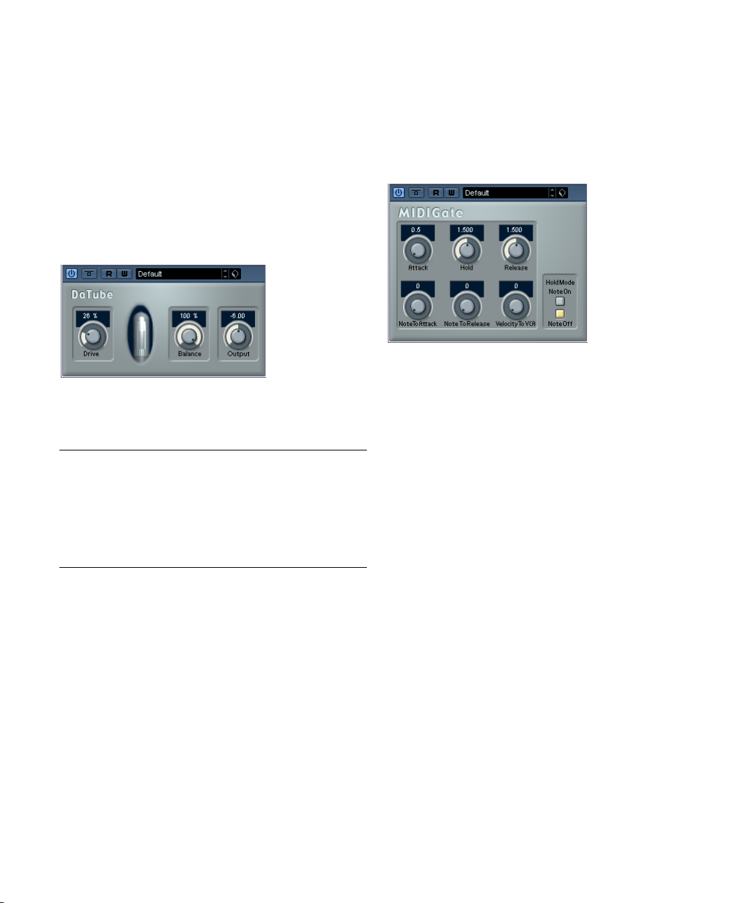
The following MIDI Gate parameters are available:
Parameter Description
Attack This is used for determining how long it should take for
Hold Regulates how long the Gate remains open after a Note
Release This determines how long it takes for the Gate to close
Note To Attack The value you specify here determines to which extent
Note To Release The value you specify here determines to which extent
Velocity To VCA This controls to which extent the velocity values of the
Hold Mode Use this switch to set the Hold Mode. In Note-On mode,
the Gate to open after receiving a signal that triggers it.
On or Note Off message (see Hold Mode below).
(in addition to the value set with the Hold parameter).
the velocity values of the MIDI notes should affect the Attack. The higher the value, the more the Attack time will
increase with high note velocities. Negative values will
give shorter Attack times with high velocities. If you do
not wish to use this parameter, set it to the 0 position.
the velocity values of the MIDI notes should affect the Release. The higher the value, the more the Release time
will increase. If you do not wish to use this parameter, set
it to the 0 position.
MIDI notes determine the output volume. A value of 127
means that the volume is controlled entirely by the velocity values, while a value of 0 means that velocities will
have no effect on the volume.
the Gate will only remain open for the time set with the
Hold and Release parameters, regardless of the length of
the MIDI note that triggered the Gate. In Note-Off mode
on the other hand, the Gate will remain open for as long
as the MIDI note plays, and then apply the Hold and Release parameters.
Filter plug-ins
This section contains descriptions of the plug-ins in the
“Filter” category.
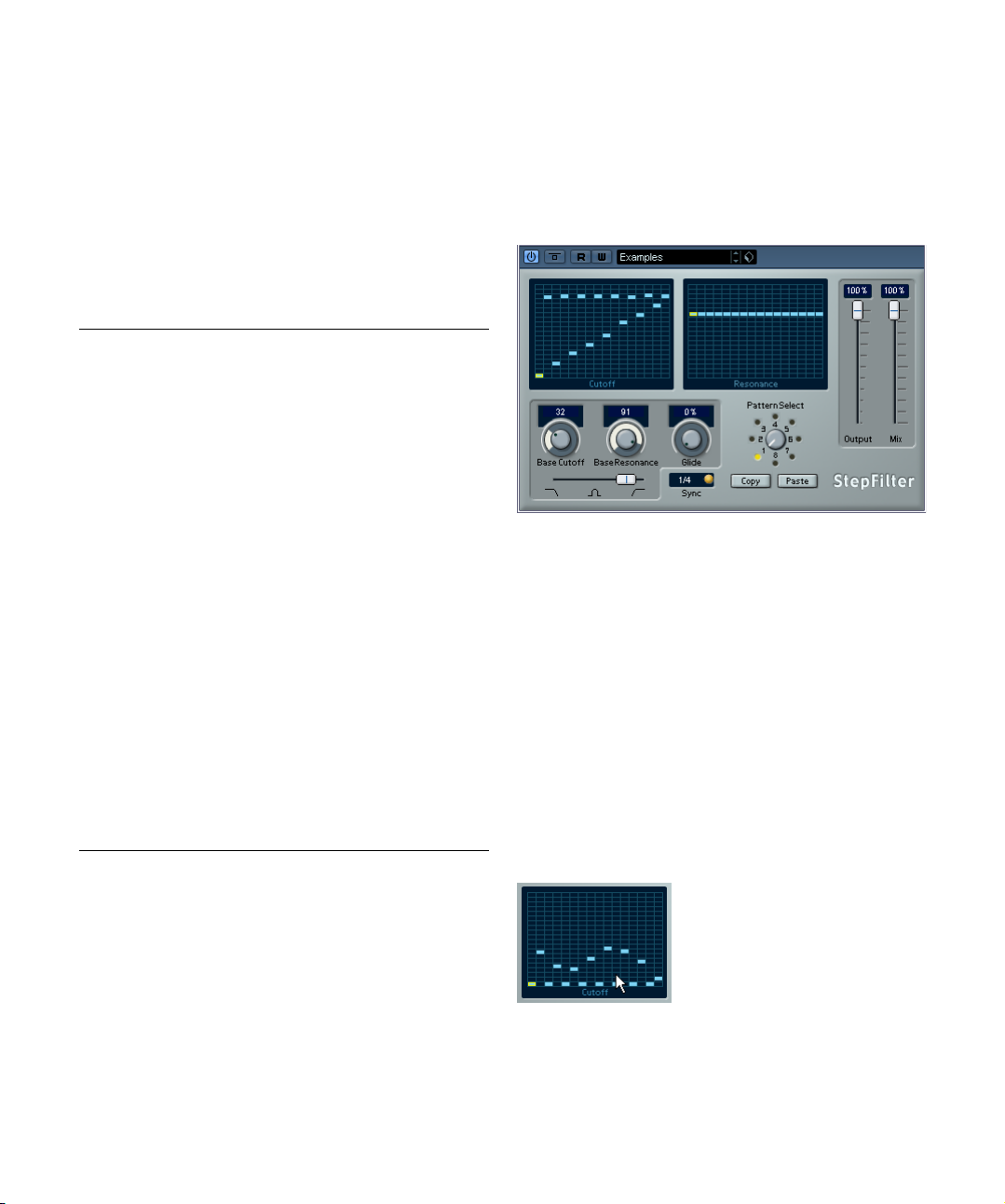
StepFilter
StepFilter is a pattern-controlled multimode filter that can
create rhythmic, pulsating filter effects.
General operation
StepFilter can produce two simultaneous 16-step patterns for the filter cutoff and resonance parameters, synchronized to the sequencer tempo.
Setting step values
• Setting step values is done by clicking in the pattern
grid windows.
• Individual step entries can be freely dragged up or
down the vertical axis, or directly set by clicking in an
empty grid box. By click-dragging left or right, consecutive
step entries will be set to the pointer position.
Setting filter cutoff values in the grid window.
28
The included effect plug-ins
Page 29

• The horizontal axis shows the pattern steps 1–16 from
left to right, and the vertical axis determines the (relative)
filter cutoff frequency and resonance setting.
The higher up on the vertical axis a step value is entered, the higher the
relative filter cutoff frequency or filter resonance setting.
• By starting playback and editing the patterns for the
cutoff and resonance parameters, you can hear how your
filter patterns affect the sound source connected to StepFilter directly.
Selecting new patterns
• Created patterns are saved with the project, and up to 8
different cutoff and resonance patterns can be saved internally.
Both the cutoff and resonance patterns are saved together in the 8 Pattern memories.
• To select new patterns you use the pattern selector.
New patterns are all set to the same step value by default.
Pattern Selector
StepFilter parameters
Parameter/
Value
Base Cutoff This sets the base filter cutoff frequency. Cutoff values
Base
Resonance
Glide This will apply glide between the pattern step values,
Filter Mode This slider selects between lowpass (LP), bandpass (BP)
Sync 1/1 to
1/32 (Straight,
Triplet or Dotted)
Output Sets the overall volume.
Mix Adjusts the mix between dry and processed signal.
Description
set in the Cutoff grid window are values relative to the
Base Cutoff value.
This sets the base filter resonance. Resonance values set
in the Resonance grid window are values relative to the
Base Resonance value. Note that very high Base Resonance settings can produce loud ringing effects at certain frequencies.
causing values to change more smoothly.
or highpass (HP) filter modes (from left to right respectively).
This sets the pattern beat resolution, i.e. what note values
the pattern will play in relation to the tempo.
Using pattern copy and paste to create
variations
You can use the Copy and Paste buttons below the pattern selector to copy a pattern to another pattern memory
location, which is useful for creating variations on a pattern.
• Select the pattern you wish to copy, click the Copy but-
ton, select another pattern memory location and click
Paste.
The pattern is copied to the new location, and can now be edited to create variations using the original pattern as a starting point.
The included effect plug-ins
29
Page 30

Modulation plug-ins
This section contains descriptions of the plug-ins in the
“Modulation” category.
Metalizer
The Metalizer feeds the audio signal through a variable
frequency filter, with tempo sync or time modulation and
feedback control.
Parameter Description
Feedback The higher the value, the more “metallic” the sound.
Sharpness Governs the character of the filter effect. The higher the
Tone Governs the feedback frequency. The effect of this will
On button Turns filter modulation on and off. When turned off, the
Mono button When this is on, the output of the Metalizer will be in
Speed If tempo sync is on, this is where you specify the base
Tempo sync on/
off
Output Sets the overall volume.
Mix Sets the level balance between the dry signal and the ef-
value, the narrower the affected frequency area, producing sharper sound and a more pronounced effect.
be more noticeable with high Feedback settings.
Metalizer will work as a static filter.
mono.
note value for tempo-syncing the effect (1/1 to 1/32,
straight, triplet or dotted). Note that there is no note value
modifier for this effect.
If tempo sync is off, the modulation speed can be set
freely with the Speed knob, without sync to tempo.
The button above the Speed knob is used to switch
tempo sync on or off. The button is lit when tempo sync is
on.
fect. If Metalizer is used as a send effect, this should be
set to maximum as you can control the dry/effect balance
with the send.
Ringmodulator
The Ringmodulator can produce complex, bell-like enharmonic sounds. Ring modulators work by multiplying two
audio signals. The ring modulated output contains added
frequencies generated by the sum of, and the difference
between, the frequencies of the two signals.
The Ringmodulator has a built-in oscillator that is multiplied with the input signal to produce the effect.
Parameter Description
Oscillator LFO
Amount
Oscillator Env.
Amount
Oscillator Wave Selects the oscillator waveform; square, sine, saw or tri-
Oscillator Range Determines the frequency range of the oscillator in Hz.
Oscillator
Frequency
Oscillator RollOff
LFO Speed Sets the LFO Speed.
LFO Env.
Amount
LFO Waveform Selects the LFO waveform; square, sine, saw or triangle.
Controls how much the oscillator frequency is affected
by the LFO.
Controls how much the oscillator frequency is affected
by the envelope (which is triggered by the input signal).
Positive and negative values can be set, with center position representing no modulation. Left of center, a loud input signal will decrease the oscillator pitch, whereas right
of center the oscillator pitch will increase when fed a loud
input.
angle.
Sets the oscillator frequency +/- 2 octaves within the selected range.
Cuts high frequencies in the oscillator waveform, to
soften the overall sound. This is best used when harmonically rich waveforms are selected (e.g. square or saw).
Controls how much the input signal level – via the envelope generator – affects the LFO speed. Positive and
negative values can be set, with center position representing no modulation. Left of center, a loud input signal
will slow down the LFO, whereas right of center a loud input signal will speed it up.
30
The included effect plug-ins
Page 31

Parameter Description
Invert Stereo This inverts the LFO waveform for the right channel of the
Envelope Generator (Attack and
Decay dials)
Lock L<R When this button is enabled, the L and R input signals
Output Sets the overall volume.
Mix Adjusts the mix between dry and processed signal.
oscillator, which produces a wider stereo perspective for
the modulation.
The Envelope Generator section controls how the input
signal is converted to envelope data, which can then be
used to control oscillator pitch and LFO speed. It has two
main controls:
Attack sets how fast the envelope output level rises in response to a rising input signal.
Decay controls how fast the envelope output level falls in
response to a falling input signal.
are merged, and produce the same envelope output level
for both oscillator channels. When disabled, each channel has its own envelope, which affects the two channels
of the oscillator independently.
Tranceformer
Tranceformer is a ring modulator effect, in which the incoming audio is ring modulated by an internal, variable frequency oscillator, producing new harmonics. A second
oscillator can be used to modulate the frequency of the
first oscillator, in sync with the Song tempo if needed.
Parameter Description
Waveform
buttons
Tone Sets the frequency (pitch) of the modulating oscillator (1
Depth Governs the depth of the pitch modulation.
Speed If tempo sync is on, this is where you specify the base
Tempo sync
on/off
On button Turns modulation of the pitch parameter on or off.
Mono button Governs whether the output will be stereo or mono.
Output Adjusts the output level of the effect.
Mix Sets the level balance between the dry signal and the ef-
Sets the pitch modulation waveform.
to 5000 Hz).
note value for tempo-syncing the effect (1/1 to 1/32,
straight, triplet or dotted). Note that there is no note value
modifier for this effect. If tempo sync is off, the modulation speed can be set freely with the Speed knob, without
sync to tempo.
The button above the Speed knob is used to switch
tempo sync on or off. The button is lit when tempo sync is
on.
fect.
Ö Note that clicking and dragging in the display allows
you to adjust the Tone and Depth parameters at the same
time!
31
The included effect plug-ins
Page 32

Other plug-ins
This section contains descriptions of the plug-ins in the
“Other” category.
Bitcrusher
If you’re into lo-fi sound, Bitcrusher is the effect for you. It
offers the possibility of decimating and truncating the input audio signal by bit reduction, to get a noisy, distorted
sound. You can for example make a 24 bit audio signal
sound like an 8 or 4 bit signal, or even render it completely
garbled and unrecognizable. The parameters are:
Parameter Description
Mode Select one of four operating modes for the Bitcrusher.
Sample Divider This sets the amount by which the audio samples are
Depth Use this to set the desired bit resolution. A setting of 24
Output Governs the output level from the Bitcrusher. Drag the
Mix This slider regulates the balance between the output
Each mode will produce a result sounding a bit different.
Modes I and III are nastier and noisier, while modes II and
IV are more subtle.
decimated. At the highest setting (65), nearly all of the information describing the original audio signal will be eliminated, turning the signal into unrecognizable noise.
gives the highest audio quality, while a setting of 1 will
create mostly noise.
slider upwards to increase the level.
from the Bitcrusher and the original audio signal. Drag
the slider upwards for a more dominant effect, and drag it
downwards if you want the original signal to be more
prominent.
Chopper
Chopper is a combined tremolo and autopan effect. It can
use different waveforms to modulate the level (tremolo) or
left-right stereo position (pan), either using tempo sync or
manual modulation speed settings. The parameters are as
follows:
Parameter Description
Waveform
buttons
Depth Sets the depth of the Chopper effect. This can also be
Speed If tempo sync is on, this is where you specify the base
Tempo sync on/
off
Stereo/Mono
button
Mix Sets the level balance between the dry signal and the ef-
Sets the modulation waveform.
set by clicking in the graphic display.
note value for tempo-syncing the effect (1/1 to 1/32,
straight, triplet or dotted). Note that there is no note value
modifier for this effect.
If tempo sync is off, the tremolo/auto-pan speed can be
set freely with the Speed knob, without sync to tempo.
The button above the Speed knob is used to switch
tempo sync on (the button lights up) or off.
Determines whether the Chopper will work as an autopanner (button set to “Stereo”) or a tremolo effect (button set to “Mono”).
fect. If Chopper is used as a send effect, this should be
set to maximum.
32
The included effect plug-ins
Page 33

Restoration plug-ins
Reverb plug-ins
This section contains descriptions of the plug-ins in the
“Restoration” category.
Grungelizer
The Grungelizer adds noise and static to your recordings
– kind of like listening to a radio with bad reception, or a
worn and scratched vinyl record. The available parameters
are as follows:
Parameter Description
Crackle This adds crackle to create that old vinyl record sound.
RPM switch When emulating the sound of a vinyl record, this switch
Noise This dial regulates the amount of static noise added.
Distort Use this dial to add distortion.
EQ Turn this dial to the right to cut off the low frequencies,
AC This emulates a constant, low hum of AC current.
Frequency
switch
Timeline This dial regulates the amount of overall effect. The far-
The farther to the right you turn the dial, the more crackle
is added.
lets you set the RPM (revolutions per minute) speed of
the record (33/45/78 RPM).
and create a more hollow, lo-fi sound.
This sets the frequency of the AC current (50 or 60Hz),
and thus the pitch of the AC hum.
ther to the right (1900) you turn this dial, the more noticeable the effect.
This section contains descriptions of the plug-ins in the
“Reverb” category.
RoomWorks SE
RoomWorks SE is a “lite” version of the RoomWorks reverb plug-in. This plug-in delivers high quality reverberation,
but has fewer parameters and is less CPU demanding than
the full version. RoomWorks SE has the following parameters:
Parameter Description
Predelay The amount of time before the onset of reverb. This al-
Time Reverb Time in seconds.
Diffusion This affects the character of the reverb tail. Higher diffu-
High Damping
Amount
Low Damping
Amount
Mix Determines the blend of dry (unprocessed) signal to wet
lows you to simulate larger spaces by increasing the time
it takes for first reflections to reach the listener.
sion is smoother while less diffusion can be clearer. This
emulates changing the types of surfaces in a room (brick
vs. carpet for instance).
This affects the decay time of high frequencies. Normal
room reverb decays quicker in the high and low frequency range than in the midrange. Lowering the damping percentage will cause high frequencies to decay
quicker. Damping percentage values above 100% will
cause high frequencies to decay longer than the
midrange.
The amount of damping applied to the low frequencies.
At 100%, no damping occurs. Values lower than 100%
increase the amount of damping, reducing low frequencies over time. Values above 100% have the opposite effect.
(processed) signal. When using RoomWorks SE inserted in an FX channel, you will most likely want to set
this to 100% or use the Send button.
33
The included effect plug-ins
Page 34

3
VST Instruments
Page 35

Introduction
VST Instruments are software synthesizers (or other
sound sources) that are contained within Cubase AI. They
are played internally via MIDI, and their audio outputs appear on separate channels in the mixer, allowing you to
add effects or EQ, just as with audio tracks.
The VST Instrument HALionOne is included with Cubase
AI, others can be purchased separately from Steinberg
and other manufacturers.
When a VST Instrument is loaded, each audio output bus
is represented by a channel strip in the mixer. When you
are working with VST Instruments that have a lot of audio
busses, this maybe a bit confusing. Therefore, you can deactivate unused output busses by clicking the corresponding button in the VST Instruments rack.
Ö This chapter describes the general procedures for
setting up and using VST Instruments.
For a description of HALionOne and its parameters, see the chapter
“HALionOne” on page 40.
Activating and using VST Instruments
VST Instruments can be activated and used in two different ways:
• By using the VST Instruments rack.
This creates an Instrument channel, which can be played by a (or several)
MIDI track(s) connected to it.
• By creating Instrument tracks.
Instrument tracks are a combination of a VST Instrument, an Instrument
channel and a MIDI track. You play and record MIDI note data directly for
this track.
In this chapter, we will describe how to set up and
!
use both Instrument channel/MIDI tracks and Instrument tracks, and also outline the main differences
between the two methods. However, for detailed descriptions of Instrument tracks, please refer to the respective chapter in the Operation Manual.
Click this button to activate the busses for the VST Instrument.
You can activate these busses at a later time.
What should I use – VST Instrument channel
or Instrument track?
Each of these two methods have their advantages, and
should be selected according to what best suits your
needs. The following applies:
Instrument tracks
• Instrument tracks feature a single MIDI input and a single stereo output.
• Instrument tracks provide a very convenient way of
quickly browsing for and auditioning preset sounds before
you actually create the track!
• All automation parameters are available directly in the
Instrument track.
This is different to a VST Instrument channel where you have both VST
Instrument channel automation and automation for the connected MIDI
track. E.g. if you move a MIDI part with Volume automation, any recorded
automation for the VST Instrument channel will not automatically follow
the moved part.
• Instrument tracks have most options that MIDI tracks
have (e.g. MIDI Modifiers) and are automated the same way.
• Instrument tracks have all options that VST Instrument
channels have, i.e. Inserts, Sends, EQ, etc.
There are certain limitations that apply to Instrument tracks:
• As there is only one stereo output available, you cannot
use multiple outputs for VST Instruments loaded as an Instrument track.
Thus, you can only use the first output channel pair of a multitimbral instrument.
35
VST Instruments
Page 36

• The MIDI volume and pan are not visible. Instead, the
VST Instrument volume and pan are displayed.
• The output device of an Instrument track always has to
be a VST Instrument.
VST Instrument channels activated from the VST
Instruments rack
• This method provides full control over multitimbral in-
struments.
You can have several MIDI tracks routed to the VST Instrument, each
playing a different part.
• Similarly, you can route channels/parts to any available
output provided by the VST Instrument.
Summing up
• If you wish to quickly browse for a particular sound, but don’t
know which VST Instrument to use, select an Instrument track.
• Do likewise if the above listed limitations do not matter.
• If you need to use multitimbral parts and/or multiple outputs,
select an Instrument channel.
Setting up VST Instrument channels
1. On the Devices menu, select VST Instruments.
The VST Instruments rack appears with 2 slots.
• If you look in the Project window track list, you will find
that a special “folder” for the selected instrument has
been added, within a “VST Instruments” folder (where all
your VST Instrument channels will appear).
The separate folder for the added VST Instrument contains two or more
automation tracks: one for automating the plug-in parameters and one
for each mixer channel used by the VST Instrument. For example, if you
add a VST Instrument with four separate outputs (four separate mixer
channels), the folder will contain five automation tracks. To keep the
screen less cluttered, you may want to close the folder for the VST Instrument until you need to view or edit any of the automation tracks.
For more about automation, see the chapter “Automation” in the Operation Manual.
• A new tab also appears in the Inspector with the name
of the VST Instrument when the MIDI track connected to
the VST Instrument is selected in the Track list.
When opened, the VST Instrument’s audio channel settings (inserts,
EQs, Sends and fader settings) are shown. If closed, the tab has two
buttons for opening the Channel Settings window (for the VST Instrument channel) and the Edit Instrument button which opens the control
panel for the VST Instrument.
2. Pull down the pop-up menu for an empty slot in the
panel and select the desired instrument.
3. You will be asked if you want to automatically create
an associated MIDI track connected to the VST Instrument. Do so.
The instrument is loaded and activated, and its control panel is automatically opened. If you pull down the output pop-up menu for the MIDI track
in the Track list or in the Inspector you can find an additional item, with
the name of the activated VST Instrument. It has automatically been selected as the output destination.
Ö In the Preferences dialog (VST–Plug-ins page) you
will find the “Create MIDI track when loading VSTi” popup menu where you can specify what should happen
when you select a VST Instrument.
VST Instruments
4. Depending on the selected VST Instrument, you may
also need to select a MIDI channel for the track.
For example, a multitimbral VST Instrument can play back different
sounds on different MIDI channels – check the VST Instrument’s documentation for MIDI implementation details.
5. Make sure the option “MIDI Thru Active” is activated in
the Preferences dialog (MIDI page).
6. Click the Monitor button for the MIDI track (in the
Track list, Inspector or mixer).
When this is activated (or when the track is record enabled), incoming
MIDI is passed on to the selected MIDI output (in this case the VST Instrument), see the chapter “Recording” in the Operation Manual.
7. Open the mixer.
You will find one or more additional channel strips for the VST Instrument’s audio outputs. VST Instrument channel strips have the same features and functionality as group channel strips, with the addition of an
Edit button at the bottom of the strip for opening the VST Instrument
control panel.
36
Page 37

8. Play the VST Instrument from your MIDI keyboard.
You can use the Channel Settings window to adjust the sound, add EQ or
effects, etc. – just as with regular audio channels. Of course, you can also
record or manually create MIDI parts that play back sounds from the VST
Instrument.
!
You can have up to 2 VST Instruments activated at the
same time, different models or several instances of the
same instrument.
• To open the control panel for the VST Instrument, click
the “Edit Instrument” button in the Inspector.
Setting up instrument tracks
Instrument tracks can be created in several different ways:
• By selecting “Add Track” on the Project menu and then selecting “Instrument” from the submenu.
• By right-clicking in the Track list and selecting “Add Instrument Track” on the context menu.
Selecting any of the two options opens a dialog where you
can specify an instrument for the track from a pop-up. You
can leave this until later if you wish. You can also specify
the number of Instrument tracks you wish to create.
• Once an Instrument track has been added, it appears in
the Track list and as an Instrument channel in the mixer.
The instrument panel does not open automatically (regardless of whether an instrument was selected in the
“Add Instrument Track” dialog or not). If a device was selected, the track will have the same name as the instrument, otherwise it will be named “Instrument Track”. Note
that VST Instruments loaded into Instrument tracks do not
show up in the VST Instruments rack. If you need a quick
overview of all VSTi’s used in a Project, use the Plug-in Information window (opened from the Devices menu).
An Instrument track in the Track list.
• In the Inspector, you can select a VST Instrument from
the Instrument pop-up.
Only VST Instruments are available on the pop-up. When you select an
instrument on this pop-up menu, its control panel is opened.
• On the Input Routing pop-up you can select a MIDI input.
Instrument tracks only have one MIDI input.
• The available Track controls and items available in the
Inspector reflect the mixed nature of Instrument tracks, as
it combines audio, VST Instruments and MIDI.
See the chapter “Instrument Tracks” in the Operation Manual for a complete listing of what items and controls are available.
• Recording/playing the instrument is done just like for
MIDI tracks.
Using VST presets
About VST presets
VST presets store all panel settings for an instrument, but
no track/channel settings.
As explained in the chapter “Audio effects” on page 5
there are also two types of VST presets that can be used;
the VST 2 standard “.fxb/.fxp” files and the new VST 3
preset standard with the extension “.vstpreset”. It works
exactly the same way for VST Instruments.
All VST 2 instruments can import “.fxb/.fxp” files and also
convert them to the VST 3 standard. Once converted you
can use all the Preset browser features. See “About ear-
lier VST Instrument presets” on page 38.
Selecting VST presets
VST Instruments come with a large number of VST presets for instant selection. Presets can either be accessed
from the control panel for the effect or from the Inspector.
To select a VST Instrument preset, proceed as follows:
1. Load a VST Instrument either by activating it from the
VST Instruments rack or by creating an Instrument track.
2. If you use a VST Instrument channel, select the MIDI
track connected to the instrument. If you use an Instrument track, select this.
37
VST Instruments
Page 38

3. If necessary, click on the track name at the top of the
Inspector to open the basic track settings.
4. Click in the Programs field in the Inspector.
This opens the Presets Browser. Selecting a new preset overwrites the
settings of the current preset so any unsaved changes will be lost.
5. To exit the browser, double-click the desired preset or
click somewhere outside the window to close it.
• You can also open the preset list from the VST Instru-
ment’s control panel. Simply click in the Preset name field.
• If you click the VST Sound button (the cube symbol),
the “Load Preset…” dialog opens.
This dialog is much like the Preset list, but there is a difference:
• If you use the “Load Preset” dialog, this allows you to
preview the settings of other presets without actually loading them. If you chose to cancel the operation, the preset
that was selected before opening the dialog will be reloaded exactly as it was, including any unsaved changes. If
you activate “Auto Preview” below the Viewer section, you
can step through the presets and play them via MIDI.
• When you use the Preset list, selecting another preset
will load it directly, replacing the previous preset.
• The Viewer section of the Load Preset dialog and the
Preset list automatically display all the available presets for
the instrument.
6. When you have selected an instrument preset, click
OK to close the Load Preset dialog or – if you used the
Preset browser – double-click the preset or click outside
the browser window to close it.
Saving VST Instrument presets
You can save your edited settings for further use (e.g. in
other projects):
1. In the VST Instrument panel, click the VST Sound button
to the right of the name field.
This opens a pop-up menu.
2. Select “Save Preset” from the pop-up menu.
This opens a dialog where you can save the current settings as a preset.
Presets are saved into a default folder named VST3 Presets. Within this folder, there is a folder named “Steinberg
Media Technologies” where the included presets are arranged in sub-folders named after each instrument.
You cannot change the default folder, but you can add further subfolders inside the instrument’s preset folder.
• Under Windows, the default preset folder is in the following location:
Boot drive/Documents and Settings/User name/Application data/VST3
Presets.
• Under Mac OS, the default preset folder is in the following location:
Users/Username/Library/Audio/Plug-Ins/Presets/
3. In the File name field in the lower part of the dialog you
can enter a name for the new preset.
4. Click OK to store the preset and exit the dialog.
About earlier VST Instrument presets
You can use any VST 2.x Instrument plug-ins in Cubase AI.
Adding VST Instrument plug-ins works the same way as
for audio effects – see “Installing additional VST plug-ins”
on page 15.
When you add a VST 2 plug-in, any previously stored presets for it will be of the old FX program/bank (.fxp/.fxb)
standard. You can import such files, but the preset handling will be slightly different. You will not be able to use
the new features like the Preview function until you have
converted the old “.fxp/.fxb” presets to VST 3 presets. If
you save new presets for a VST 2 plug-in these will automatically be saved in the new “.vstpreset” format in the
default location.
38
VST Instruments
Page 39

Importing and converting FXB/FXP files
To import .fxp/.fxb files, proceed as follows:
1. Load any VST 2 instrument you may have installed, and
click on the VST Sound button to open the Preset Management pop-up menu.
2. Select “Import FXB/FXP” from the pop-up.
This menu item is only available for VST 2 instrument plug-ins.
3. In the file dialog that opens, locate the file and click
Open.
If you loaded a Bank, it will replace the current set of all programs. If you
loaded a single preset, it will replace the currently selected preset program only.
4. After importing, you can convert the current program
list to VST Presets by selecting “Convert Program List to
VST Presets” from the Preset Management pop-up.
After converting, the presets will be available. The new converted presets will be stored in the VST3 Preset folder.
About latency
Depending on your audio hardware and its ASIO driver,
the latency (the time it takes for the Instrument to produce
a sound when you press a key on your MIDI controller)
may simply be too high to allow comfortable real-time VST
Instrument playback from a keyboard.
If this is the case, a workaround is to play and record your
parts with another MIDI Sound Source selected, and then
switch to the VST Instrument for playback.
However, when you play a VST Instrument in real time or
record live audio (with monitoring through Cubase AI activated), this delay compensation may sometimes result in
added latency. To avoid this, activate the Constrain Delay
Compensation button on the Project window toolbar. This
function tries to minimize the latency effects of the delay
compensation, while maintaining the sound of the mix as
far as possible.
• In the Preferences dialog (VST page) you will find a setting called Delay Compensation Threshold. Only plug-ins
with a delay higher than the value entered here will be affected by the Constrain Delay Compensation function.
• VST plug-ins (with higher delay than the threshold
value) which are activated for VST Instrument channels,
audio track channels that are record enabled, group channels and output channels will be turned off when you activate Constrain Delay Compensation.
• VST plug-ins activated for FX channels are not turned
off but their delay is disregarded by the program (delay
compensation is turned off).
After recording or using a VST Instrument with Constrain
Delay Compensation, you should turn off the function to
restore full delay compensation.
Ö You can check the latency for your audio hardware in
the Device Setup dialog (VST Audio System page).
The input and output latency values are shown below the ASIO Driver
pop-up menu. For live VST Instruments playing, these values should ideally be a few milliseconds (although the limit for “comfortable” live playing
is a matter of personal taste).
Constrain Delay Compensation
Cubase AI features full delay compensation throughout the
entire audio path. This means that any delay inherent in the
VST plug-ins you use will automatically be compensated for
during playback, so that all channels are kept in perfect
sync (see “About plug-in delay compensation” on page 6).
VST Instruments
Automating a VST Instrument
• Automation of the VST Instrument channel settings is
done in the same way as automating regular channels.
• Automation of the specific parameters for a VST Instrument is done in the same way as automating VST effect
parameters.
See the chapter “Automation” in the Operation Manual.
39
Page 40

4
HALionOne
Page 41

Introduction
Parameter Description
DCA Release Controls the DCA signal after a key is released.
DCA Amount Controls the amount of the DCA (amplifier) envelope.
As stated earlier, other parameters may be shown; these
will be clearly labelled on the panel. For most of the presets there are also associated effects – the effect parameters are usually located to the right on the panel and
typically control the dry/wet mix of the effect.
HALionOne is a sample player that can play sound content
in the *.hsb (HALion Sound Bank) format. These samples
have associated preset files that store the panel settings
and reference the HSB samples. Included are several presets (as *.vstpreset files).
The operation of HALionOne is very simple; load a preset
and start playing! You also can tweak the basic parameters to tailor the sound to your liking.
HALionOne parameters
The HALionOne panel parameters shown can vary according to which parameters are stored in the HSB file.
HSB files cannot be created with HALionOne – you need
the full version of HALion to do this – but when created,
certain parameters are assigned as part of the file and the
associated program (or preset). This means that for each
preset, only these assigned parameters are shown on the
instrument panel. Typically, these are filter cutoff, DCA
and DCF parameters and any assigned effect parameters
(the effects are “built in”).
If you load HALionOne for an Instrument track and don’t
select a preset, the following main parameters are shown:
Parameter Description
Cutoff This allows you to adjust filter frequency or cutoff. The fil-
Resonance Raising the filter resonance value will emphasize the fre-
DCF Amount Controls the amount of the DCF (filter) envelope.
DCA Attack Controls the time it takes for the DCA signal to reach its
DCA Decay Controls the time it takes the DCA signal to decay to the
DCA Sustain Controls the DCA signal level after the Decay phase, as
ter used is a Waldorf Low Pass filter with a 24 dB slope.
quencies around the set filter frequency.
highest level.
sustain level.
long as you press the key on your MIDI keyboard.
Effects Bypass
• This button, located at the bottom right in the box displaying the preset name, allows you to bypass any effects.
The blue LED beside the button is lit if any effects are used in the preset.
Efficiency slider
The Efficiency slider provides a way of balancing audio
quality vs. conservation of computer power. The lower the
setting, the more voices are available. As a trade-off, sound
quality is reduced.
Voices allocated
The Voices field dynamically displays the number of
voices currently used.
MIDI and Disk activity LEDs
The MIDI activity LED indicates received MIDI input. The
Disk LED will light up green when samples are streamed
from disk, and red when samples cannot be loaded from
disk in time. In such a case you should consider lowering
the Efficiency slider.
Locate Contents
If you have moved the HALionOne content files to a different location (i.e. any other location than the folder in which
it was stored during the installation), you need to use the
Locate Contents function to inform HALion One about
where to find its files. This is done as follows:
• Right-click anywhere on the control panel and select
“Locate contents”.
A file dialog opens where you can navigate to the folder location.
41
HALionOne
Page 42

Index
Page 43

A
Audio effects
About 6
Editing 12
For output busses (Master
inserts) 8
Inserts 7
Organizing in subfolders 16
Post-fader inserts 7
Pre/Post fader sends 11
Saving 14
Selecting Presets 13
Selecting VST Presets 37
Sends 10
Tempo sync 6
B
Bitcrusher 32
Bypass
Effect sends 11
Insert effects 8
C
Channel Overview
Insert effects 8
Chopper 32
Constrain Delay Compensation 39
D
DaTube 27
Delay compensation
About 6
Constraining 39
Disable inserts 8
Disable sends 11
E
Effect Return channels 12
Effects, see “Audio effects”
F
Flanger 23
FX channel tracks
About 9
Adding effects for 10
Routing sends to 10
Setting up 9
Soloing 12
G
Gate 20
Group channel tracks
Using effects 9
Grungelizer 33
H
HALionOne
About 41
Parameters 41
I
Insert effects
About 7
L
Limiter 20
M
Metalizer 30
MIDI Gate 27
MonoDelay 19
MonoToStereo 26
Mute Pre-Send when Mute 11
O
Octaver 25
P
Phaser 23
PingPongDelay 19
Plug-in delay compensation 6
Plug-in Information window
About 16
Plug-ins
Getting info 16
Installing VST 2.x 15
Organizing 16
Pre fader sends 11
R
Ringmodulator 30
RoomWorks SE 33
Rotary 24
Routing
Effect sends 11
S
Send effects 9
Solo Defeat 12
StepFilter 28
StereoEnhancer 26
T
Tracks
Routing MIDI to VST
Instruments 36
Tranceformer 31
Tremolo 24
Tuner 25
V
VST Instrument tracks
Setting up 37
VST Instruments
Activating 35
Automating 39
Channels 36
HALionOne 41
Routing tracks to 36
Saving VST Presets 38
Using VST Presets 37
VST plug-ins
Getting info 16
Installing 15
VSTDynamics 21
43
Index
 Loading...