

Page 1
Contents
Introduction 3
Description of symbols 3
Specifications 3
Safety rules for laser lights 4
General safety instructions 4
Electrical safety 5
Additional safety rules for band saws 6
Extension cords 6
Accessories 7
Unpacking 7
Assembly time 7
R
equired tools 7
Know your product
Components 9
Assembly 10
Mounting to a workbench 11
Upper blade guide adjustment 11
Lower blade guide adjustment 12
Housing Doors 12
Adjusting the rip fence 13
Adjusting the miter gauge 13
Adjusting the bevel angle 13
Adjusting the saw blade tension 14
Adjusting the blade tracking 14
Setting the table square with the blade 15
Dust collector connection 15
Turning on and off 15
Turning the worklight on and off 15
Fitting the light bulb 16
Turning the laser on and off 16
Installing and removing band saw blades 16
Operation 17
Using the REDEYE laser line generator 17
Maintenance 18
Troubleshooting 18
Parts and parts listing 19
Warranty 22
8
WARNING! To Reduce The Risk Of Injury, User
Must Read And Understand Instruction Manual.
2
Page 2
Dear Customer
If you require any help with your product,
whether it is a Warranty claim, spare part or
user information, please phone our Help Line
888-896-6881 for an immediate response.
Introduction
Your new Steele® power tool will more
than satisfy your expectations. It has been
manufactured under stringent Steele® Quality
Standards to meet superior performance criteria.
You will find your new tool easy and safe to
operate, and, with proper care, it will give you
many years of dependable service.
Caution.
Instruction
Steele® Power Tool. Take special care to
heed the Cautions and Warnings.Your
Steele® power tool has many features that
will make you job faster and easier. Safety
performance and depend ability have been given
top priority to the development of this tool, making
it easy to maintain and operate.
Carefully read through this entire
Manual before using your new
Environmental protection
Recycle unwanted materials instead
of disposing of them as waste. All
tools, hoses and packaging should
be sorted, taken to the local
recycling center and disposed of in
an environmentally safe way.
WARNING.It may be more difficult to see the
laser line in conditions of bright
sunshine and on cer tain surfaces.
Description of symbols
The rating plate on your tool may show symbols. These
represent important information about the product or
instructions on its use.
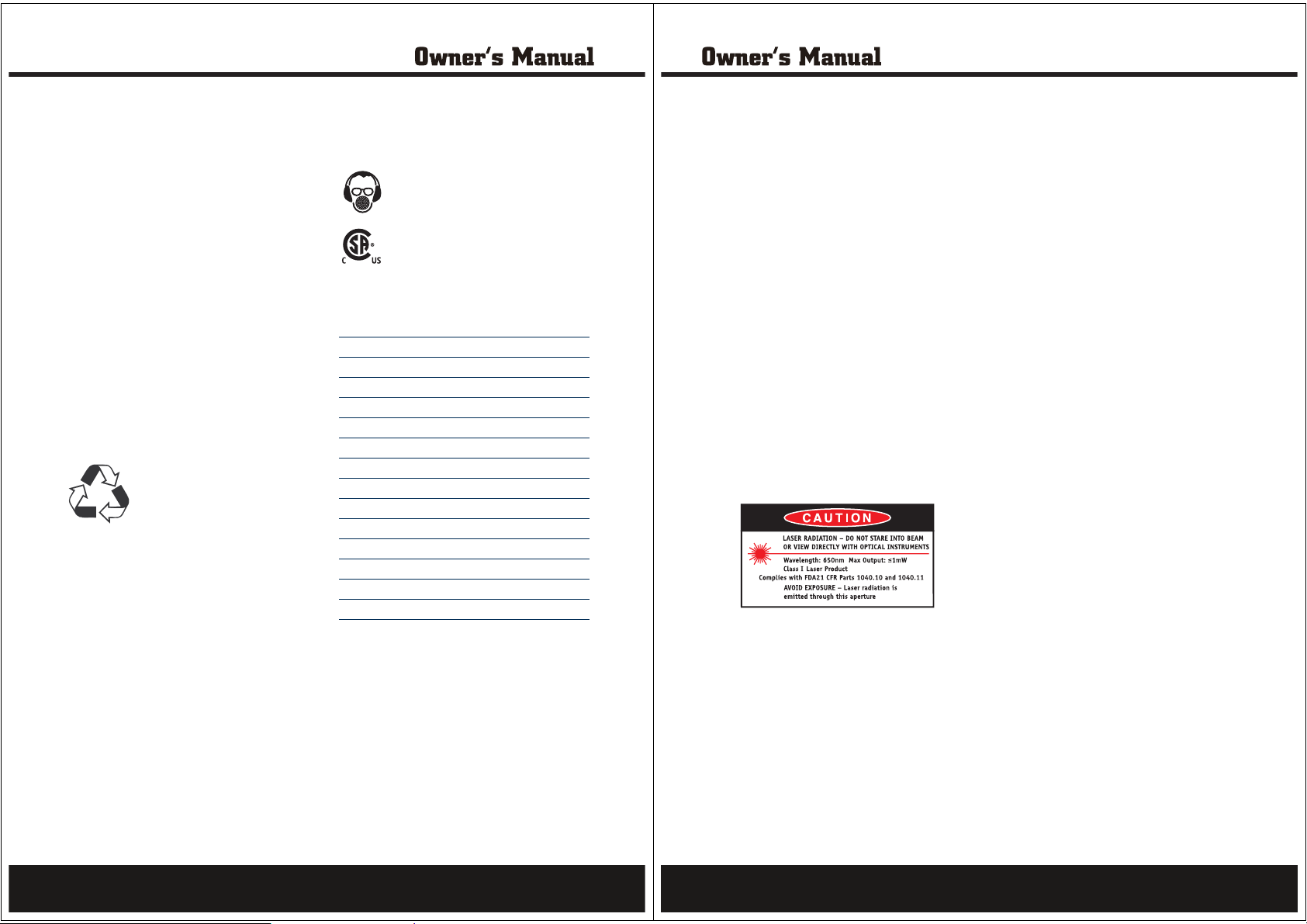
Wear hearing protection.
Wear eye protection.
Wear breathing protection.
The ‘C’ and ‘US’ indicators adjacent to the
CSA Mark signify that the product has been
evaluated to the applicable CSA and ANSI/UL
Standards, for use in Canada and the U.S.,
respectively.
Specifications
Amp: 2.0
RPM: 2650 ft/min
Throat Depth: 9”
Cutting Capacity: 3-1/2”
Table Size: 11-13/16” x 11-13/16”
Blade Size: 59-1/2”
Bevel Angle: 0° to 45°
Laser class: I
Laser wavelength: 650nm
Laser output power: ᱽ 1mW
Replacement lamp: 120V Max 15W E12
Insulation class: I “Earthed Appliance”
ight: 40.3 lbs
We
V : volts ~ : alternating current
Hz : hertz nm : nanometers
A : ampere mW : milliwatt
Safety rules for laserlights
The laser guide used in the tool is Class I with a
maximum output of 1mw and a wavelength of
650nm. The laser guide does not normally present
an optical hazard, although staring at the beam may
cause flash blindness.
USER INFORMATION
CAUTION.
this laser product will increase the chance of eye
damage.
Do not stare into the laser beam.
The laser shall be used and maintained in
accordance with the manufacturer’s instructions.
Never aim the beam at any person or an object
oth
Always ensure the laser beam is aimed at a
sturdy work piece without a reflective surface,
i.e. wood or rough coated surfaces are
acceptable. Bright shiny reflective sheet or the
like is not suitable for laser use as the reflective
surface could direct the beam back at the
operator.
General safety instructions
WARNING.
Failure to follow all instructions listed below, may
result in electric shock, fire and/or serious personal
injury.
Save these instructions.
1. Keep guards in place and in working order.
2. Remove adjusting keys and wrenches.
The use of optical instruments with
er than the work piece.
Read and understand all instructions.
3. Keep work area clean.Cluttered areas and benches
invite accidents.
4. Don’t use in dangerous environment. Don’t use
ols in damp or wet locations, or expose
power to
them to rain. Keep work area well lighted.
5. Keep children away. All visitors should be kept
safe distance from work area.
6. Make the workshop kid proof with padlocks,
master switches, or by removing starter keys.
7. Don’t force the tool. It will do the job better and
safer at the rate for which it was designed.
8. Use the right tool. Don’t force tool or attachment
to do a job for which it was not designed.
9. Use the proper extension cord. Make sure your
extension cord is in good condition. When using
an extension cord, be sure to use one heavy
enough to carry the current your product will
draw. An undersized cord will cause a drop in
line voltage resulting in loss of power and
overheating. The table on page 7 of this manual
shows the correct size to use depending on cord
length and nameplate ampere rating. If in doubt,
use the next heavier gage. The smaller the gage
number, the heavier the cord.
10. Wear proper apparel. Do not wear loose
clothing, gloves, neckties, rings, bracelets, or
other jewelry which may get caught in moving
parts. Nonslip footwear is recommended.
Wear protective hair covering to contain long
hair.
11. Always use safety glasses. Also use face or
dust mask if cutting operating is dusty.
Everyday eyeglasses only have impact
resistant lenses: they are not safety glasses.
12. Secure work. Use clamps or a vise to hold
work when practical. It’s safer than using your
hand and it frees both hands to operate the tool.
13. Don’t overreach. Keep proper footing and
balance at all times.
3
4
Page 3
14. Maintain tools with care. Keep tools sharp and
clean for best and safest performance. Follow
instructions for lubricating and changing
accessories.
15. Disconnect tools before servicing; when
changing accessories, such as blades, bits,
cutters, and the like.
16. Reduce the risk of unintentional starting.
Make sure switch is in “off” position before
plugging in.
17. Use recommended accessories. Consult the
owner’s manual for recommended accessories.
The use of improper accessories may cause
risk of injury to persons.
18. Never stand on tool. Serious injury could
occur if the tool is tipped or if the cutting tool
is unintentionally contacted.
19. Check damaged parts. Before further use of
the tool, a guard or other part that is damaged
should be carefully chec
kedtodetermineifit
will operate properly and perform its intended
function – check for alignment of moving par ts,
binding of moving parts, breakage of parts,
mounting, and any other conditions that may
affect its operation. A guard or other part that
is damaged should be properly repaired or
replaced.
20. Direction of feed. Feed work into a blade or
cutter against the direction of rotation of the
blade or cutter only.
21. Never leave the tool running unattended.
Turn power off. Don’t leave tool until it comes
to a complete stop.
Electrical safety
• In the event of a malfunction or breakdown,
grounding provides a path of least resistance for
electrical current to reduce the risk of electric
shock. This tool is equipped with an electric cord
that has an equipment grounding conductor and
a grounding plug. The plug MUST be plugged
into a matching outlet that is properly installed
and grounded in accordance with ALL local
codes and ordinances.
• Do not modify the plug provided. If it will not fit
the outlet, have the proper outlet installed by a
qualified electrician.
• Improper connection of the equipment grounding
conductor can result in a risk of electric shock.
The conductor with the green insulation (or
without yellow stripes) is the equipment
grounding conductor. If repair or replacement of
the electric cord or plug is necessary, DO NOT
connect the equipment grounding conductor
to
aliveterminal.
• Check with a qualified electrician or service
personnel if you do not completely understand
the grounding instructions, or if you are not sure
the tool is properly grounded.
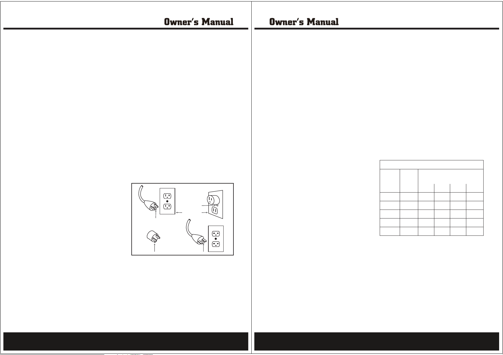
• Use only a three wire extension cord with a
3-prong grounding type plug and 3-hole
receptacles that accept the tool’s plug as shown
in the diagram.
• Repair or replace damaged or worn cords
immediately.
Metal Screw
Cover of Grounded
Grounding
Pin
Adapter
Grounding
Means
Outlet Box
Grounding
Pin
Additional safety rules for band saws
Ensure that the lighting is adequate.
For your own safety read Instruction Manual
Before Operating Saw
Wear eye protection.
Do not remove jammed cutoff pieces until the
blade has stopped.
Maintain proper adjustment of blade tension,blade
guides,and thrust bearings.
Adjust upper guide to just clear workpiece.
Hold workpiece firmly against table.
Ensure that the lighting is adequate.
Keep the area free of tripping hazards.
Do not let anyone under 18 years operate this saw.
Always stand to one side when operating the saw.
Never use a cracked or distor ted saw blade. Only
use sharp blades.
Never use your hands to remove sawdust, chips
or waste close by the saw blade.
Use only blades as recommended.
Rags, cloths, cord, string and the like should
never be left around the work area.
Avoid cutting nails. Inspect the workpiece and
remove all nails and other foreign objects before
beginning sawing.
Do not attempt to free a jammed blade before
first switching off the machine.
Do not slow or stop a blade with a piece of wood.
Let the blade co
If you are interrupted when operating the saw,
complete the process and switch off before
looking up.
Periodically check that all nuts, bolts and other
fixings are
Do not store materials or equipment above a
machine in such a way that they could fall into it.
me to rest naturally.
properly tightened.
Ensure that your work is always on the table.
Never make a cut with the work off the table.
Wear goggles
Wear ear protection
Wear a breathing mask
Extension cords
Replace damaged cords immediately. Use of
damaged cords can shock, burn or electrocute.
If an extension cord is necessary, a cord with
adequate size conductors should be used to
prevent excessive voltage drop, loss of power or
overheating. The table shows the correct size to
use, depending on cord length and nameplate
amperage rating of tool. If in doubt, use the next
heavier gauge. Always use U.L. and CSA listed
extension cords.
RECO MMENDED SIZES OF EXTEN SIO N COR DS
Tool’s
Ampere
rating
3–6 120V~ 18 16 16 14
6–8 120V~ 18 16 14 12
8–10 120V~ 18 16 14 12
10–12 120V~ 16 16 14 12
12–16 120V~ 14 12 - -
Volts Total length of cord in feet
Cord size in A.W.G.(minimum)
25ft 50ft 100ft 150ft
5
6
Page 4
Accessories
The STEELE®Band Saw is supplied with the
following accessories as standard
• 59 -1/ 2” band saw blade (fiited)
• Rip Fence
• Miter Gauge
• Light Bulb
• Wrench
• Hex Keys (x2)
• Instruction Manual
• Receipt Holder
Unpacking
Due to modern mass production techniques, it is
unlikely that your STEELE® Power Tool is faulty or
that a part is missing. If you find anything wrong,
do not operate the tool until the parts have been
replaced or the fault has been rectified. Failure to do
so could result in serious personal injury.
Assembly Time
Assembly consists of attaching the table, table
insert, rip fence and miter gauge. Assembly will
take approximately 10-15 minutes.
RequiredTools
The following tools are required:
• 0.16”(4mm)Hex Key(supplied)
• 0.12”(3mm)Hex Key(supplied)
• Wrench (supplied)
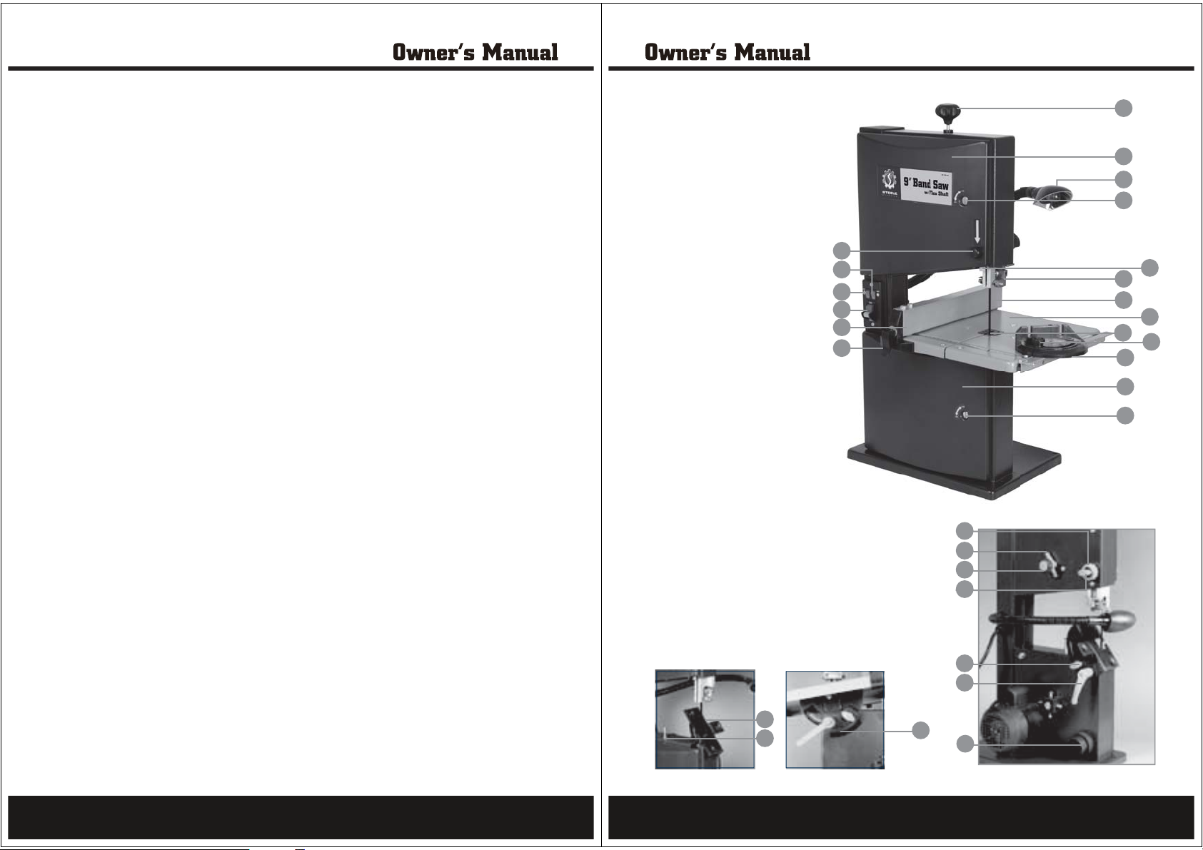
Know your product
1. On/Off switch
2. Laser light on/off switch
3. Light on/off switch
4. Laser adjustment knob
5. Laser aperture
6. Work table trunnion
7. Work table
8. Table insert
9. Table tilt adjustable screw stop
10.Upper housing locking screw
11.Upper housing door
12.Lower housing locking screw
13.Lower housing door
14.Saw blade
15.Blade tension knob
16.Rip fence
17.Rip fence locking handle
18.Miter gauge
19.Miter gauge locking knob
20.Upper blade guide
21.Blade guide adjustment knob
22.Blade guide locking knob
23.Blade tracking adjustment knob
24.Blade tracking locking nut
25.Table locking knob
26.Table setting lever
27.Bevel adjustment scale
28.Dust extraction
29.Adjustable worklight
port
16
17
15
11
29
10
4
3
2
1
21
24
23
22
20
14
8
18
13
12
5
7
19
25
26
6
9
7
27
28
8
Page 5
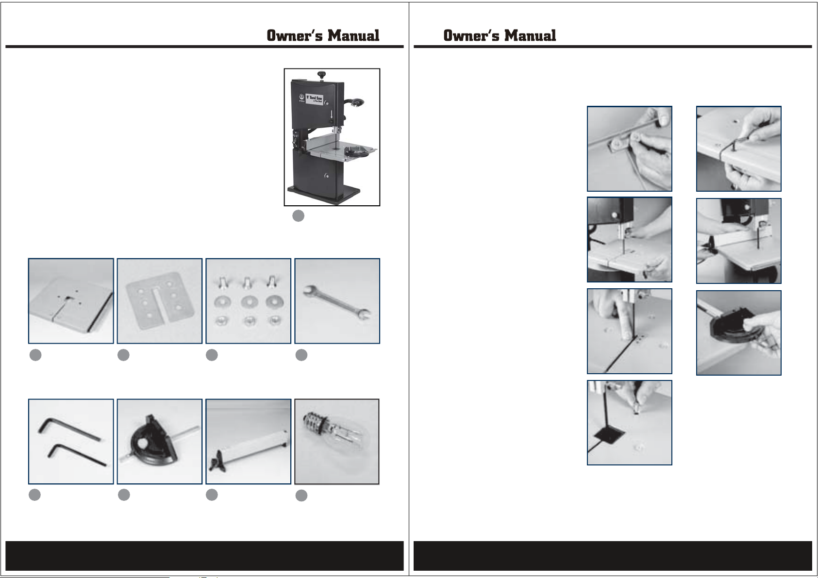
Components
The band saw is supplied with the following components:
1. Band Saw
2. Table
3. Table Insert
4. Recessed hex bolt, washer and nuts (x3)
5. Wrench
6. Hex keys (x2)
7. Miter Gauge
8. Rip Fence
9. Light Bulb
2
3 5
Assembly
The band saw is shipped partly disassembled and the work table
and rip fence have to be installed prior to use.
1. Remove the bracket from below
the work table by loosening the
2 knobs. Remove the 2 knobs,
bracket and screws.
2. Place the work table on the table
trunnion by threading the saw
blade through the slot in the
table.
3. I nsert the table insert in the
centre of the table.
1
4
4. Align the work table so that the
blade runs through the centre of
the table insert’s slot.
5. Fasten the work table to the table
trunnion using the three recessed
hex bolts, plain washers and
nuts.
Caution: Make sure the screws are
tightened securely to ensure they
do not loosen in use.
6. Replace the bracket under the
work table using the two screws
and two thumb nuts.
7. Attache the rip fence to the table
and secure it by pushing down
the rip fence locking handle.
Note.It may be necessary to
rotate the handle anticlockwise
to be able to slide the rip
fence over the table and then
clockwise before locking the
handle in position.
8. Attach the miter gauge onto the
table by sliding it into the miter
gauge slot.
6
7
8
9
9
10
Page 6
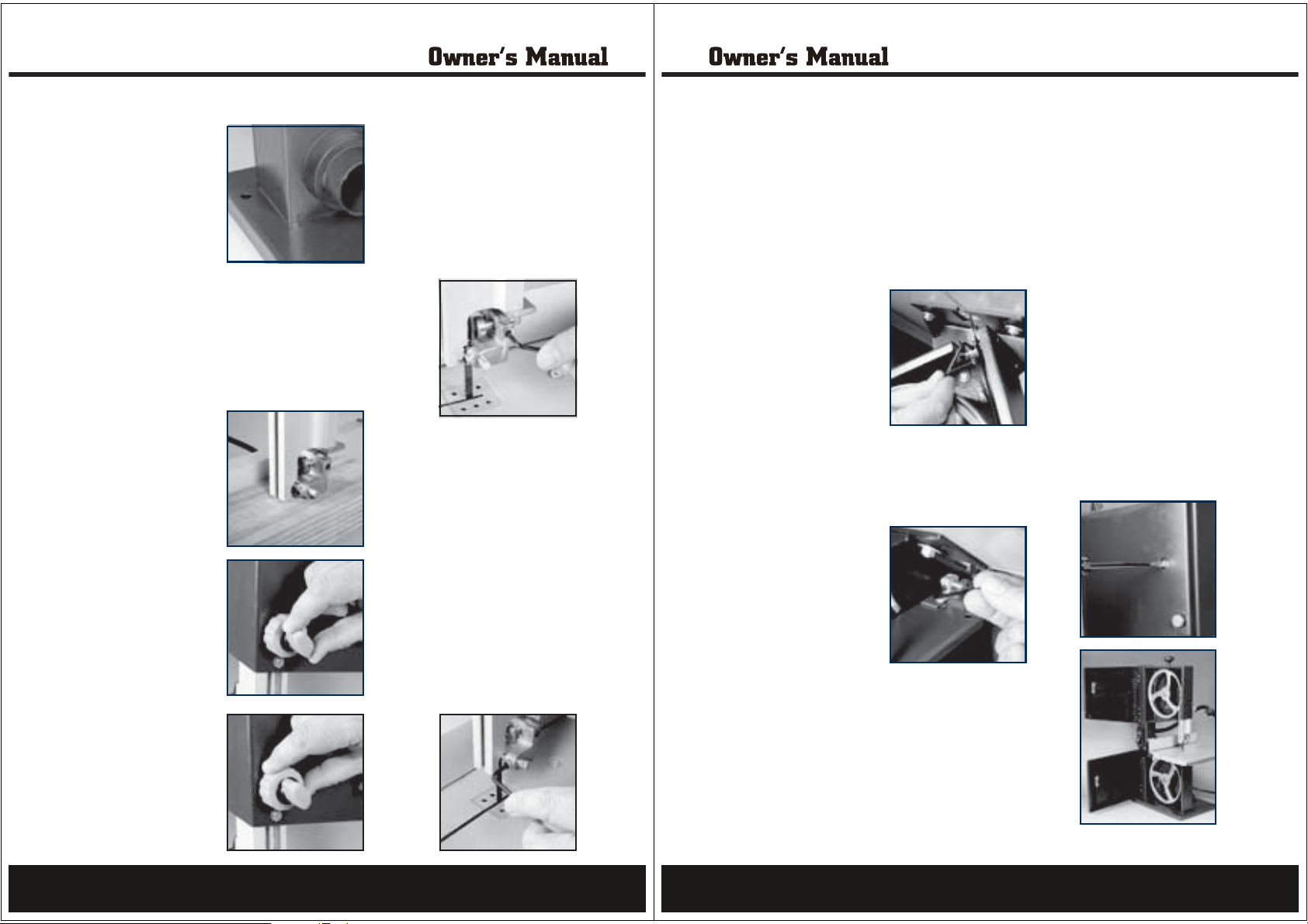
Mounting to a workbench
1. selohruofserutaefdnabehT
in the base for mounting to a
workbench.
2. dnabehthcattaottsebsitI
saw to a firm, stable surface at
a convenient working height. A
workbench is ideal.
3. ehtniselohruofllirD
workbench to match the four
holes in the base of the saw.
4. detresni(stlobgnisuhcnebkrow
from the top), lock washers and nuts.
ehtotwasdnabehthcattA
Upper blade guide adjustment
WARNING.Always ensure that the saw is switched off
and unplugged from the power supply before making any
adjustments.
uehT.1
against unintentional contact
with the saw blade.
guide to provide adequate
protection against contact with
the band saw blade, it must
always be set as close as
possible against the workpiece
(maximum distance 1/8 inch).
upper blade guide loosen the
blade guide locking knob and
then adjust the height using the
blade guide adjustment knob.
gedalbehtnethgiT.4
knob to secure the upper blade
guide in position.
consists of a thrust bearing
that supports the band saw
blade from the rear a
guide pins that provide lateral
support, these need to be
readjusted after every band
saw blade change or tracking
adjustment.
stcetorpediugedalbrepp
edalbreppuehtrofredronI.2
ehtfothgiehehttsujdaoT.3
gnikcolediu
ediugedalbreppuehT.5
nd two
Thrust bearing adjustment
To adjust the thrust bearing loosen the
.1
thrust bearing locking screw using the
Allen key supplied.
position until it isgniraebtsurhtehttsujdA.2
1/32 inch away from the band saw blade.
When the band sawblade is turned by
hand it should not make contact with the
thrust bearing.
3. Tighten the thrust bearing locking screw.
Upper guide pin adjustment
sen the 2oolsnipediugehttsujdaoT.1
screws that hold the guide pins in place
using the Allen key supplied.
against therehtegotsnipediugehtsserP.2
band saw blade.
and in ableehwwasdnabehtnruT.3
yh
clockwise direction several times to
bring the guide pins into the correct
position.Both guide pins should just
touch the saw blade.
4. Tighten the guide pin locking screws.
Caution: Ensure the blade is not pinched
by rotating the band saw wheel one or
two times by hand.
Lower blade guide adjustment
tsurhtafostsisnocstnemtsujdaediugedalbrewolehT.1
bearing that supports the band saw blade from the rear and
two guide pins that provide lateral support, these need to be
readjusted after every band saw blade change or tracking
adjustment.
tsurhtehterofeb°54detlitebotsdeenelbatkrowehT.2
bearing locking screw and guide pins can be adjusted. This
helps give better access to the adjustment screws.
Thrust bearing adjustment
gniraebtsurhtehttsujdaoT.1
loosen the thrust bearing
locking screw using the Allen
key supplied. It
access the thrust bearing
screw if the work table
trunnion is placed on a 45°
angle.
position until it is 1/32 inch away from the band saw blade.
When the band saw blade is turned by hand it should not
make contact with the thrust bearing.
3. Tighten the thrust bearing locking screw.
Lower guide pin adjustment
adjust the guide pins by
loosening the 2 screws that
hold the guide pins in place
using the Allen key supplied.
The lower housing door needs
to be opened to access the
screws.
against the ban
Note: The right guide pin is accessed through the slot in the
lower housing.
several times to bring the guide pins into the correct
position. Both guide pins should just touch the saw blade.
Caution: Ensure the blade is not pinched by rotating the band
saw wheel one or two times by hand.
is easier to
gniraebtsurhtehttsujdA.2
levelnoinnurtelbatehthtiW.1
rehtegotsnipediugehtsserP.2
d saw blade.
noitceridesiwkcolcanidnahybleehwwasdnabehtnruT.3
.swercsgnikcolnipediugehtnethgiT.4
Housing doors
WARNING.Always ensure that
the saw is switched off and
unplugged from the power supply
before making any adjustments.
roodgnisuohreppuehT.1
and lower housing door
protect against contact with
the rotating par
machine.
closed and locked, while the
machine is in use.
door rotate the upper housing
locking screw to the left and
then open the door.
oT.4
door rotate the lower housing
locking screw to the left and
then open the door.
ts inside the
ebtsumsroodgnisuohhtoB.2
gnisuohreppuehtnepooT.3
gnisuohrewolehtnepo
11
12
Page 7
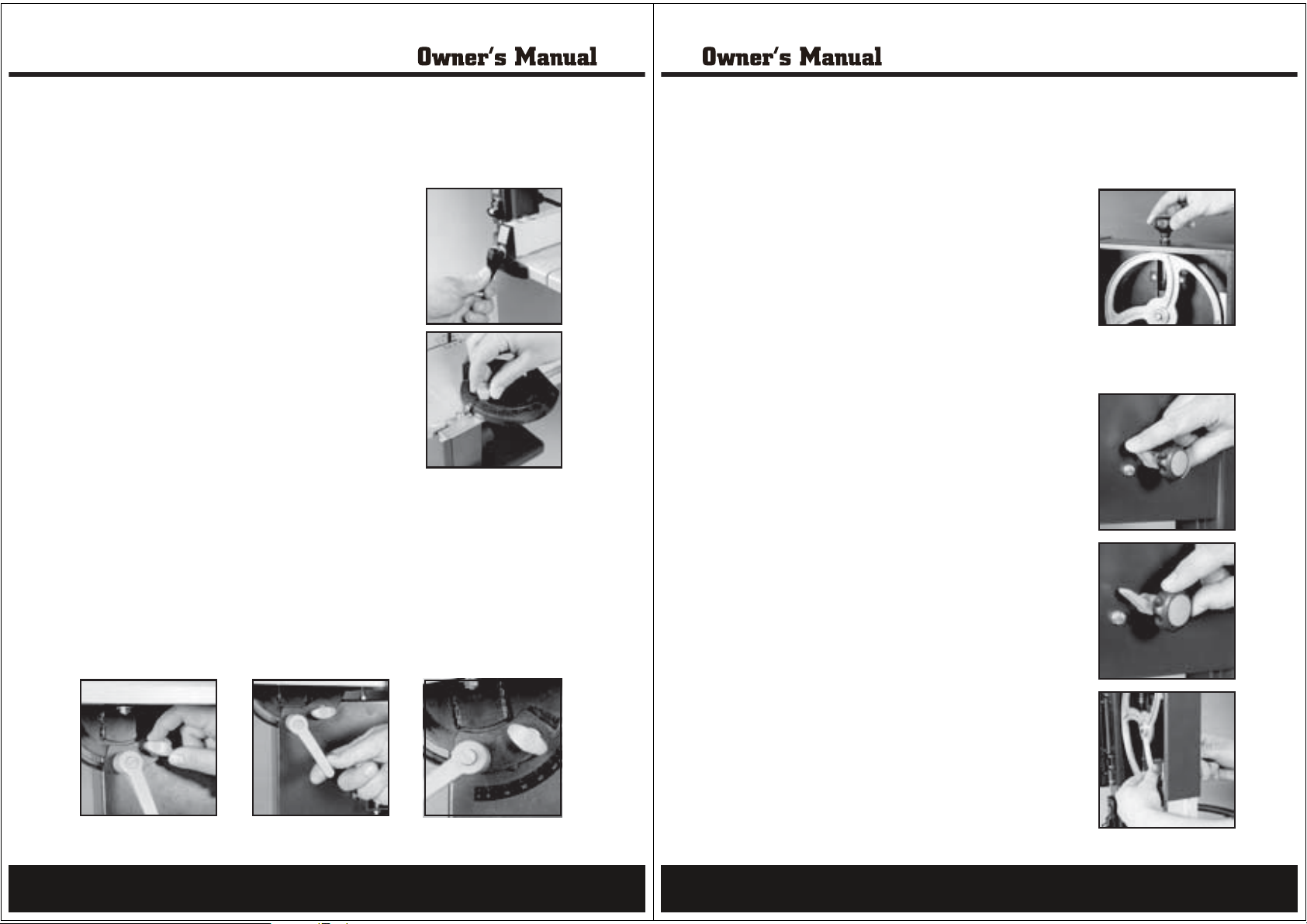
Adjusting the rip fence
WARNING.Always ensure that the saw is switched off and unplugged from the power supply before
making any adjustments.
The rip fence allows you to make parallel cuts in a piece of wood, all at the same width.
erequired width and secure it in positionhtotecnefpirehttsujdA.1
using the rip fence locking handle.
positioned on both sides of the bladeebnacecnefpirehT.2
snE.3
length to give a consistent parallel cut.
s against the wood along its entiretserecnefehttahteru
Adjusting the miter gauge
1. o helptdesusieguagretimehT
support the workpiece and can be
adjusted when cutting an angle.
2. loosen theeguagretimehttsujdaoT
knob at the top of the miter gauge.
3. ehtlitnueguagretimehtetatoR
desired angle is reached.
4. Tighten the miter gauge knob to secure the angle.
Adjusting the bevel angle
WARNING.Always ensure that the saw is switched off and unplugged from the power supply before
making any adjustments.
The bevel adjustment allows material to be cut at an angle from 0° to 45°.
knob.gnikcolelbatehtnesooL.1
The lever works on a cam allowing you to pull it towards you and back.revelgnitteselbatehtnesooL.2
into the original starting position if you run out of room.
tnemtsujdalevebA.3
s located under the table to assist in setting the table to the desired angleielacs
between 0° and 45°
tehtnethgiT.4
adjust the table as necessary for your requirements.
and the table locking knob to secure the table in position.revelgnitteselba
required, make a practice cut first on a scrap piece of similar wood and thensinoisicerpretaergnehW.5
Adjusting the saw blade tension
WARNING.Always ensure that the saw is switched off and unplugged from the power supply before making
any adjustments.
The saw blade tension can be adjusted using the blade tension knob.
n turn the blade tension knob inoisnetedalbehtesaercnioT.1
a clockwise direction.
n turn the blade tension knob inoisnetedalbehtecuderoT.2
an anti-clockwise direction.
guide.edalbreppuehtesiarylluF.3
disehtgnihsupybnoisnetehtkcehC.4
finger halfway between the table and upper blade guide. The
blade should flex no more than 5/64 to 1/
5. Correct the tension if necessary.
8 inch.
ruoyhtiwedalbehtfoe
Adjusting the blade tracking
WARNING.Always ensure that the saw is switched off
and unplugged from the power supply before making any
adjustments.
The blade tracking adjustment knob is used to adjust the upper
band saw wheel to have the blade run dead centre on the
rubber tyres of the band saw wheels.
g locking nut.nikcartedalbehtnesooL.1
wheel by hand, turn the bladewasdnabehtgnitatorelihW.2
tracking adjustment knob in a clockwise direction if the band
saw blade runs towards the front of the saw.
adjustment knob in an anticlockwisegnikcartedalbehtnruT.3
direction if the ba
ethgiT.4
Note: Rotate the bandsaw wheel by hand to check the blade is
correctly aligned before closing and locking the housing doors
and running the band saw.
nd saw blade runs towards the rear of the saw.
locking nut.gnikcartedalbehtn
13
14
Page 8
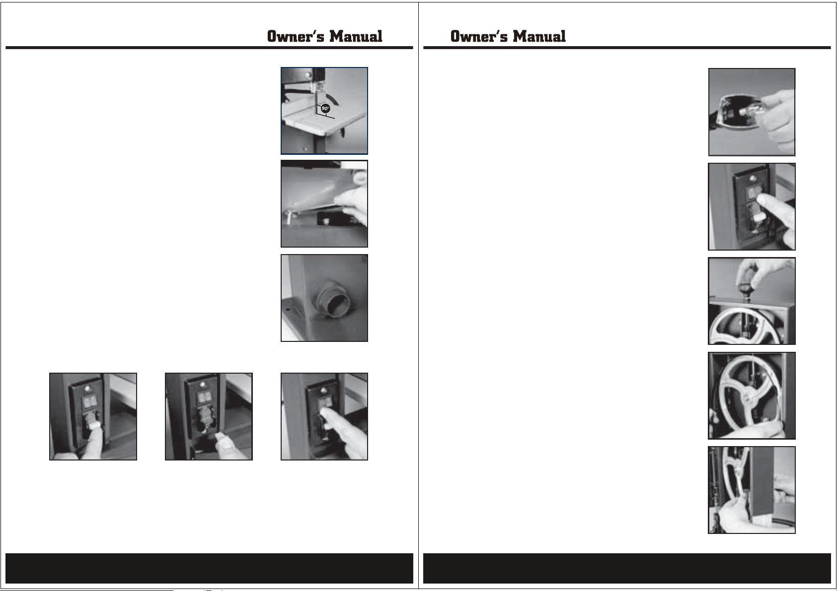
Setting the table square with the blade
WARNING.Always ensure that the saw is switched off and unplugged
from the power aqbefore making any adjustments.
guide.edalbreppuehtesiarylluF.1
w tension is correct.asdnabehttahtkcehC.2
b and table setting lever.onkgnikcolelbatehtnesooL.3
work table at a right angle to the blade.ehttsujda,erauqsagnisU.4
b (25) and table setting lever (26).onkgnikcolelbatehtnethgiT.5
d beneath the work table andetacoltungnikcolehtnesooL.6
adjust the screw stop until it touches the work table.
o secure the screw stop
Note: Check the blade is 90° to the table by cutting a scrap
piece of wood and checking it is square.
in position.ttungnikcolehtnethgiT.7
Dust collector connection
n equipment to the dustoitcartxetsudtcennoC.1
extraction port on the back of the band saw.
CAUTION.Wood dust and chips in a confined area can give rise
to fire or an explosion. Guard against possible ignition sources.
Keep the saw dust to a minimum by cleaning up after every use.
Turning on and off
the switch disabling inser ttresniwasdnabehttratsoT.1
and move the switch up to the ‘ON’ position.
e ‘OFF’ position to turn the band sa
g insert to prevent unauthorized use andnilbasidhctiwsehtevomeR.3
store it in a secure location out of reach of children.
woff.htotnwodhctiwsehtevoM.2
Turning the worklight on and off
s the light on/off switch to the “I” position.serpnothgilkrowehtnrutoT.1
s the light on/off switch to the “O” position.serpffothgilkrowehtnrutoT.2
e light move the worklight tube to the most suitable position.htfonoitceridehttsujdaoT.3
Fitting the light bulb
into the light housing.tiwercsdnablubthgilehtekaT.1
flexible tube allowing it to be positioned where itanodetacolsithgilehT.2
will project the most light onto the work area.
Turning the laser on and off
“I” position. ehtothctiwsffo/nothgilresalehtsserpnoresalehtnrutoT.1
e laser light on/off switch to the “O” position. htsserpfforesalehtnrutoT.2
jdaoT.3
direction to loosen it and then move it to the left or right until the laser line
is in line with the blade. Turn the laser adjustment knob in a clockwise
direction to tighten it.
the laser adjustment knob in an anti-clockwisenrutenilresalehttsu
Installing and removing band saw blades
WARNING.Always ensure that the saw is switched off and unplugged from
the power supply before making any adjustments.
This bandsaw is supplied with a general purpose woodcutting blade.
m the table.orfecnefpirehtevomeR.1
m under the work table by loosening the two knobs. orftekcarbehtevomeR.2
3. Open both housing doors.
n knob to slacken the blade.oisnetedalbehtnesooL.4
g it through the slot in the work table, the uppernidiugybedalbehtevomeR.5
blade guide and the blade cover on the saw housing.
g that the teeth are pointing towards the frontni
rusne
edalbwaswenehttiF.6
of the saw where the doors are.
knob. noisnetedalbehtgnitatorybedalbwenehtnoisnetylthgiL.7
tnoedalbwasdnabehtertneC.8
of the rubber-lined wheels.
I.01
Adjust the thrust bearing and guide pins as described earlier.
12. Close both housing doors.
ttA.41
screws and two thumb nuts.
down the rip fence locking handle.
blade tracking.wasehttsujda,deriuqerf
tighten the blade tension knob. ,tcerrocsignikcartehtecnO.11
e back into position.diugedalbrewolehtgniwS.31
esdnaelbatehtotecnefpirehthcattA.51
saw wheels. dnabehtfoserytrebbureh
in the centregninnursiedalbehterusneotdnahybleehwreppuehtnruT.9
owtehtgnisuelbatkrowehtrednuepahsUehthca
gnihsupybtieruc
15
16
Page 9
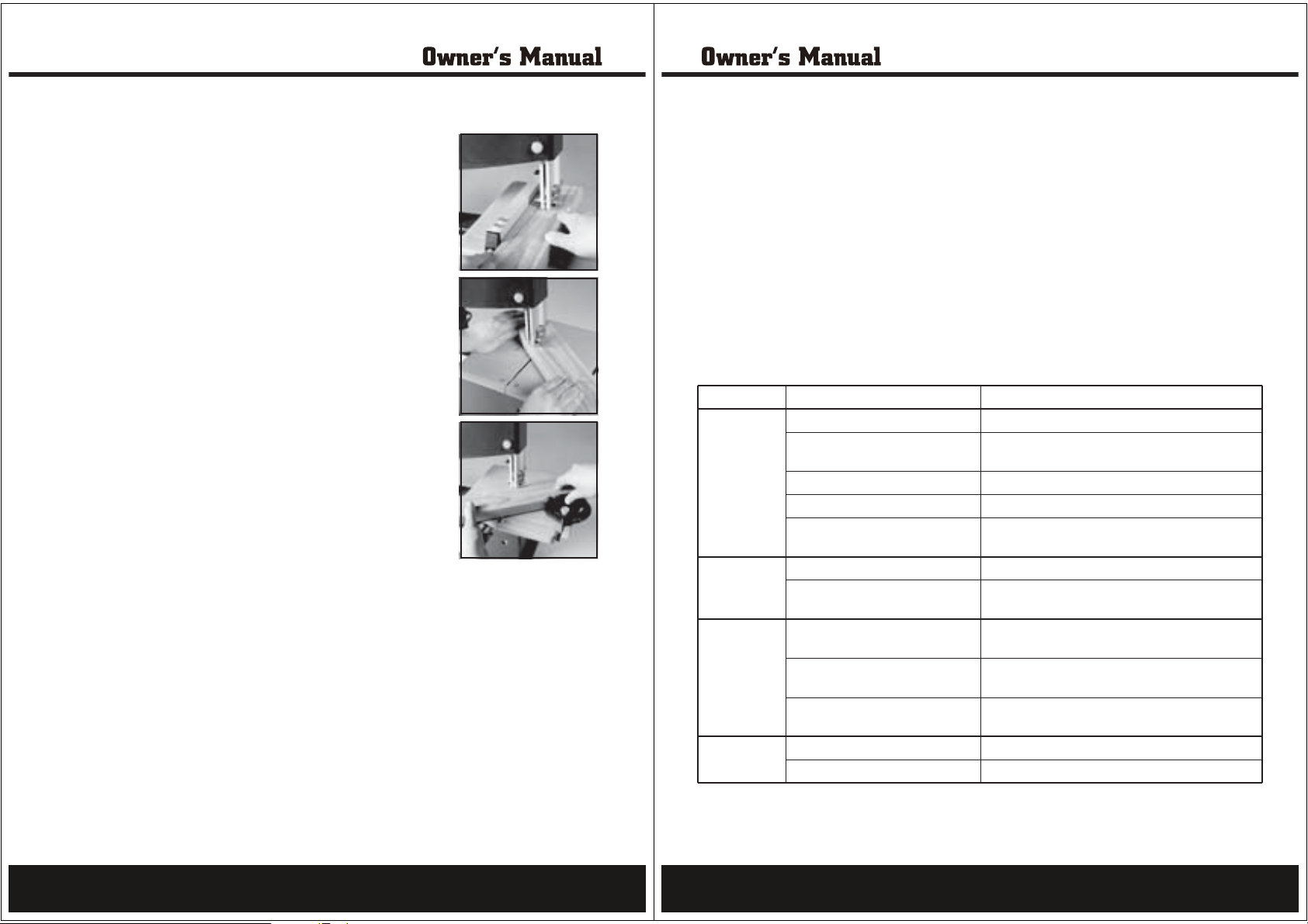
Operation
p fence, miter gauge and upper blade guide asir,elgnalevebehttsujdA.1
required.
t is in place and flush with the table.resnielbatehttahterusnE.2
/n/off switch to the ‘ON’ position.oehthsupwasehttratsoT.3
e wood into the moving saw blade.htediugtucehtnigeboT.4
o keep the saw cutting. Do not force the
terusserphguoneylnoesU.5
cutting, allow the blade and the saw to do the work.
e ensure that the rip fence is located on thelgnalevebanognittucnehW.6
right hand side of the blade.
When cutting rod,use a jig or fixture to prevent the workpiece from turning.7
,use a suitable push bl
workpiece into the saw.
ehtgnihsupyblootehtffonrutdehsinifecnO.9
position and unplug the tool from the power point to prevent
unauthorized use.
ock to feed theyllacitrevsdraobgnittucnehW.8
to the ‘OFF’hctiwsffo/no
Using the REDEYE laser line generator
WARNING. Do not stare directly at the laser beam. Never aim the beam at
any person or an object other than the workpiece.Do not deliberately aim
the beam at personnel and ensure that it is not directed towards the eye
of a person.Always ensure the laser beam is aimed at a sturdy workpiece
without reflective surfaces. i.e. wood or rough coated surfaces are
acceptable. Bright shiny
laser use as the reflective surface could direct the beam back at the operator.
Only turn the laser beam on when the work piece is on the tool.
1. Mark the line of cut on the work piece.
3. Switch on the laser beam using the laser light on/off switch.
4. Align the laser beam with the line on the work piece.
bresalehT.5
adjustment knob and move the laser beam until it is in line with the blade. Tighten the laser adjustment
knob.
6. To start the saw push the
7. To begin the cut guide the wood into the moving saw blade.
to do the work.
nittucnehW.11
tool from the power point to prevent unauthorised use.
reflective sheet steel or the like is not suitable for
on/off switch to the ‘ON’ position.
nognittucnehW.9
e workpiece from turning.httneverpoterutxifrogijaesu,dorgnittucnehW.01
blade guide as required.reppudnaeguagretim,ecnefpir,elgnalevebehttsujdA.2
by adjusting the laser line. Loosen the laseredalbehthtiwlellarapebotdengilaebnacmae
force the cutting, allow the blade and the sawtonoD.gnittucwasehtpeekoterusserphguoneylnoesU.8
located on the right hand side of the blade.siecnefpirehttahterusneelgnaleveba
to feed the workpiece into the saw.kcolbhsupelbatiusaesu,yllacitrevsdraobg
p
ressing the red ‘OFF’ button and unplug theyblootehtffonrut,thgilresalehtffonrutdehsinifecnO.21
Maintenance
All the bearings are sealed ball bearings, lubricated
for life, and require no maintenance.
Cleaning
1. Keep the tool’s air vents unclogged and clean at
all times.
stebsigninaelC.ylralugertriddnatsudevomeR.2
done with a soft brush or a rag.
3. Re-lubricate all moving parts at regular intervals.
4. Never use caustic agents to clean plastic parts.
CAUTION.Do not use cleaning agents to clean the
plastic parts of the tool. A mild detergent on a damp
cloth is recommended.
General inspection
Regularly check that all the fixing screws are tight.
They may vibrate loose over time.
Repairs
Only an authorized service center should replace the
cordset or carry out other repairs. If the cordset is
damaged or worn, have it repaired or replaced by an
authorized service center.
Troubleshooting
Warning!Turn the on/off switch to the off position and unplug the tool from the power supply before performing
trouble shooting procedures.
Trouble Problem Suggested remedy
Band saw will
not start
Blade does not
reach full speed
Blade not
running straight
Vibration or
abnormal noise
Power cord not plugged in
Power fault, fuse or circuit breaker
tripped
Cord damaged Use authorized service center to repair or replace
Burned out switch Use authorized service center to repair or replace
Faulty motor Use authorized service center to repair or replace the
Extension cord too long or undersized Use extension cord heavy enough to carry the current
Tool is overheating Turn off the tool and let it cool down to room
Loose blade
Blade tracking not adjusted Ensure that the blade is centered on the wheels by
Thrust bearings and guide pins not
adjusted
Loose parts Check to see that all screws
Moving parts excessively worn Use authorized service center to repair or replace
Ensure that the cord is connected to the power supply
Check the power supply
motor
temperature. Inspect and clean the ventilation slots
Check to see that the blade is tightened on the wheels,
adjust the blade tension if necessary
adjusting the blade tracking
Adjust all thrust bearings and guide pins as
recommended
17
18
Page 10
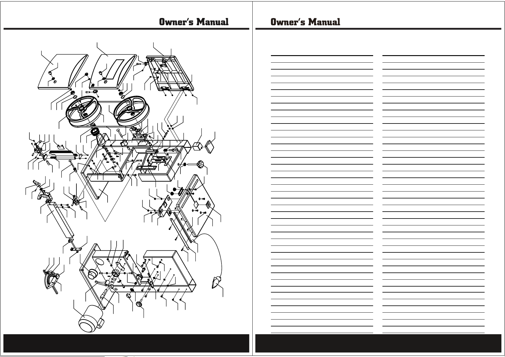
PARTS
46
37
46
52
53
69
109
106
4
9
14
13
75
76
77
78
70
34
70
34
70
12
105
10
11
12
19
20
79
80
82
81
91
92
98
34
99
59
103
104
32
15
16
17
18
86
95
102
87
88
96
93
94
116
83
84
89
90
97
103
100
101
59
36
36
Parts Listing
APA Parts NO. Factory No. Description
PB140-01-DD DJ23004201 Upper Case Door
PB140-02-DD DJ23004103 Lock Core
PB140-03-DD 31503022 Gasket
PB140-04-DD DJ23004101 Nether Case Door
PB140-05-DD S16E05010 Adjust Knob
PB140-06-DD GB97.1 Washer(ĭ6)
PB140-07-DD RLM08011 Laser Localizer
PB140-08-DD GB845 Tap Screw(St4.2×9.5)
PB140-09-DD DJ23004104 Laser Fixer
PB140-10-DD 31503030 Metal Patch
PB140-11-DD GB862.2 Dentate Gasket(ĭ6)
PB140-12-DD GB5783 Hex Head Screw(M6×10)
PB140-13-DD DJ200020506 Cable Clamp Board
PB140-14-DD GB/T845 Tap Screw(St3.5×9.5)
PB140-15-DD DJ23004102 Table-flap
PB140-16-DD GB12618 Rivet(ĭ4×8)
PB140-17-DD GB818 Bolt(M4×6)
PB140-18-DD GB96 Washer(ĭ4)
PB140-19-DD DJ250A03007 Horizontal Axis
PB140-20-DD GB896 E-Clamp(ĭ6)
PB140-21-DD DJ23003101 Upper Wheel
PB140-22-DD GB893.1 Clamp Ring(ĭ26)
PB140-23-DD GB/T276 Ball Bearing(6000-2z)
PB140-24-DD GB894.1 Spring Washer(ĭ10)
PB140-25-DD DJ23003102 Rubber Ring
PB140-26-DD DJ23003001 Saw Blade
PB140-27-DD DJ23003201 Nether Wheel
PB140-28-DD DJ23003202 Belt Pulley
PB140-29-DD DJ23003002 Motor Wheel
PB140-30-DD DJ23003003 Multiwedge Belt
PB140-31-DD GB6173 Nut(M16x1.5)
PB140-32-DD GB5783 Hex Bolt(M6×10)
PB140-33-DD GB93 Spring Washer(ĭ6)
PB140-34-DD GB96 Washer(ĭ6)
PB140-35-DD GB12 Knob-square Bolt(M6×20)
PB140-36-DD GB845 Phillips Tap Screw(St4.2×9.5)
PB140-37-DD GB845 Phillips Tap Screw(St3.5×9.5)
PB140-38-DD DJ200030411 Dust Guard
PB140-39-DD DJ205A03003 Upper Guide Slide Bar
PB140-40-DD DJ200030410 Slide Board
PB140-41-DD GB12 Knob-square Bolt(M6×20)
APA Parts NO. Factory No. Description
PB140-42-DD DJ200030402 Gear
PB140-43-DD DJ250A03018 Rack
PB140-44-DD DJ200030501 Lock Pole
PB140-45-DD DJ200030409 Upper Guide Stator
PB140-46-DD GB80 Socket Head Screw(M6×8)
PB140-47-DD GB80 Socket Head Screw(M6×6)
PB140-48-DD DJ200030502 Upper Guide Axis
PB140-49-DD DJ250A03022A Upper Guide
PB140-50-DD DJ250A03021 Mini-guide Roller Axis
PB140-51-DD GB/T276 Ball Bearing(625-zz)
PB140-52-DD S16E04006 Lock Spanner
PB140-53-DD GB879 Pin(ĭ3×16)
PB140-54-DD DJ23002102 Connecting
PB140-55-DD GB97.1 Washer(ĭ10)
PB140-56-DD DJ23002101 Baffle Rack
PB140-57-DD DJ250A02008A-2 Clamp Block
PB140-58-DD DJ200020202A Baffle
PB140-59-DD GB97.1 Washer(ĭ6)
PB140-60-DD DJ250A02008A-4 Clamp Baffle
PB140-61-DD DJ200020203A Clamp Screw
PB140-62-DD DJ200030601 Nether Guide Rack
PB140-63-DD DJ200030602 Nether Guide Staff
PB140-64-DD DJ200020401 Guide Staff
PB140-65-DD DJ250B02007-3 Finger
PB140-66-DD B/D4603011-3 Knob
PB140-67-DD DJ250B02007-1 Angle Block Gauge
PB140-68-DD DJ23001000 Base
PB140-69-DD GB5783 Hex Bolt(M6×16)
PB140-70-DD GB6170 Hex Nut(M6)
PB140-71-DD GB5783 Hex Bolt(M6×35)
PB140-72-DD DJ200030701 Bushing
PB140-73-DD 31504015 Brush
PB140-74-DD GB14 Knob-square Bolt(M8×65)
PB140-75-DD KCD1-B3B10111BB Switch
PB140-76-DD HY7 Key Switch
PB140-77-DD GB819 Phillips Sunk Head Screw(M4×12)
PB140-78-DD DJ23005001A Switch Case
PB140-79-DD DJ200040106 Cable Jacket
PB140-80-DD DJ200030301 Upper Wheel Axis
PB140-81-DD DJ250A03003B Upper Wheel Axis Rack
PB140-82-DD GB/T1792 Spring(A16)
4
1
2
3
24
23
48
51
47
40
50
49
45
44
54
55
56
57
58
65
64
5
6
28
22
27
29
39
43
41
47
59
57
17
66
67
28
38
37
36
42
63
51
47
62
12
50
60
112
61
113
115
2
3
21
25
26
32
30
31
18
35
68
111
114
7
8
24
23
22
74
73
33
72
34
70
71
59
110
70
108
107
105
105
19
20
Page 11
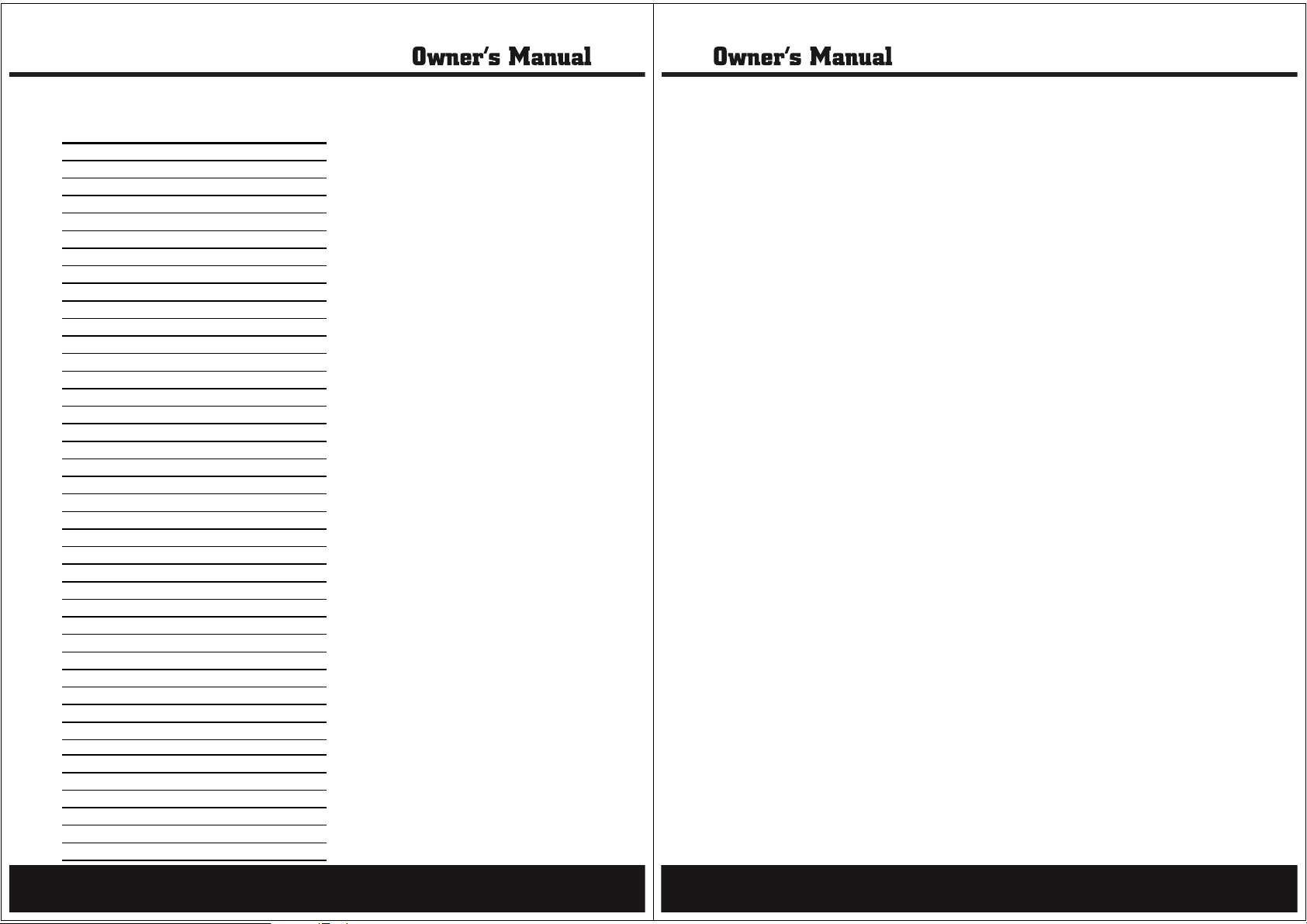
Parts Listing
Limited Warranty
APA Parts NO. Factory No. Description
PB140-83-DD DJ200030303 Core Axis
PB140-84-DD DJ250A03009 Nut
PB140-85-DD DJ250A03010 U-Rack
PB140-86-DD DQ018002100 DC-Plugboard
PB140-87-DD DJ200010401 Cap
PB140-88-DD DJ23003300 Knob Handle
PB140-89-DD DJ200030304 Fixed Ring
PB140-90-DD DJ200030900 Guide Board Subassembly
PB140-91-DD GB6177 Hex Flange Nut(M6)
PB140-92-DD DJ205A03002 Guide Piece
PB140-93-DD DJ200020107 Blade Cross Block
PB140-94-DD DJ200020101A Worktable
PB140-95-DD GB/T70.3 Socket Sunk Head Screw(M6×16)
PB140-96-DD GB/T70.3 Socket Sunk Head Screw(M6×20)
PB140-97-DD DJ250C02004 Adjust Level Board
PB140-98-DD 31502013 Compound Nut
PB140-99-DD DJ200020100-1 Revoliving Rack Subassembly
PB140-100-DD GB/T818 Phillips Screw(M4×20)
PB140-101-DD DJ200020301A Side Slide Board
PB140-102-DD DJ23002001 Support Rod
PB140-103-DD GB/T6170 Hex Nut(M4)
PB140-104-DD 31503007 Wing Nut
PB140-105-DD DJ200030406 Lock Knob
PB140-106-DD GB894.1 Wing Cap
PB140-107-DD DJ200030407 Spring
PB140-108-DD DJ200030405 Adjust Handle
PB140-109-DD DJ200030402 Gear
PB140-110-DD DJ200020108 Lock Gasket
PB140-111-DD GB5783 Hex Bolt(M6×20)
PB140-112-DD DJ200010107A Imbibition Exit
PB140-113-DD DJ200020102 Lock Handle
PB140-114-DD DJ23003004 Nether Wheel Axis
PB140-115-DD YYG7124E-T Motor
PB140-116-DD 5000034521 Work Light Subassembly
PB140-117-DD
Steele® warrants to the original purchaser who uses the product in a consumer application (personal,
residential or household usage) that all products covered under this warranty are free from defects in
material and workmanship for one year from the date of purchase. All products covered by this limited
warranty which are used in commercial applications (i.e. income producing) are warranted to be free of
defects in material and workmanship for 90 days from the date of original purchase. Products covered
under this warranty include air compressors, tools, service parts, pressure washers and generators.
Steele® will repair or replace, at Steele®’s sole option, products or components which have failed within
the warranty period. Service will be scheduled accor
ding to the normal work flow and business hours at
the service center location, and the availability of replacement parts. All decisions of Steele® with regard
to this limited warranty shall be final.
This warranty gives you specific legal rights, and you may also have other rights which vary from state to
state.
RESPONSIBILITY OF ORIGINAL PURCHASER (initial User):
To process a warranty claim on this product, DO NOT return item to the retailer. The product must be
evaluated by an Authorized Warranty Service Center. For the location of the nearest Authorized Warranty
Service Center contact the retailer or place of purchase.
Retain original cash register sales receipt as proof of purchase for warranty to work.
Use reasonable care in the operation and maintenance of the
product as described in the Owner’s
Manual(s).
Deliver or ship the product to the Authorized Warranty Service Center. Freight costs, if any must be paid
by the purchaser. If the purchaser does not receive satisfactory results form the Authorized Warranty
Service Center, the purchaser should contact Steele® toll free 888-896-6881.
THIS WARRANTY DOES NOT COVER:
Merchandise sold as reconditioned, used as rental equipment, or floor or display models.
Merchandise that has become damaged or inoperative because of ordinary wear, misuse, cold, heat, rain,
excessive humidity, freeze damage, use of improper chemicals, negligence, accident, failure to operate the
product in accordance with the instructions provided in the Owner’s Manual(s) supplied with
the product,
improper maintenance, the use of accessories or attachments not recommended by Steele®, or
unauthorized repair or alterations.
Repair and transportation costs of merchandise determine not to be defective.
Costs associated with assembly, required oil, adjustments or other installation and start-up costs.
Expendable parts or accessories supplied with the product which are expected to become inoperative or
unusable after a reasonable period of use.
21
22
Page 12
Merchandise sold by Steele® which has been manufactured by and identified as the product of another
company, such as gasoline engines. The product manufacturer’s warranty, if any, will apply.
ANY INCIDENTAL, INDIRECT OR CONSEQUENTIAL LOSS, DAMAGE, OR EXPENSE THAT MAY RESULT
FROM ANY DEFECTS, FAILURE OR MALFUNCTION OF THE PRODUCT IS NOT COVERED BY THIS
WARRANTY. Some states do not allow the exclusion, so it may not apply to you.
IMPLIED WARRANTIES, INCLUDING THOSE OF MERCHANTABILITY OR FITNESS FOR A PARTICULAR
PURPOSE, ARE LIMITED TO ONE YEAR FROM THE DATE OF ORIGINAL PURCHASE. Some states do not
allow limitations on how long an implied warranty lasts, so the above limitations may not apply to you.
Distributed by:
730 S.Epperson Dr.
City Of Industry,CA91748
www.steele-products.com
all rights reserved
23
 Loading...