

Page 1
WARNING
Some dust created by power sanding, sawing, grinding, drilling, and other construction activities
contains chemicals known to the State of California to cause cancer, birth defects or other
reproductive harm. Some examples of these chemicals are:
Lead from lead-based paints.
Crystalline silica from bricks, cement, and other masonry products.
Arsenic and chromium from chemically treated lumber.
Your risk from these exposures varies, depending on how often you do this type of work. To reduce
your exposure to these chemicals: work in a well ventilated area, and work with approved safety
equipment, such as those dust masks that are specially designed to filter out microscopic particles.
The Model SP-PB130 is specifically designed for cutting operations. DO NOT MODIFY AND/OR USE
THIS MACHINE FOR ANY OTHER PURPOSE. MODIFICATIONS OR IMPROPER USE OF THIS TOOL
WILL VOID THE WARRANTY. If you are confused about any aspect of this machine, DO NOT use it
until all your questions have been answered.
WARNING! To Reduce The Risk Of Injury, User
Must Read And Understand Instruction Manual.
2
Page 2
Contents
INTRODUCTION
INTRODUCTION . . . . . . . . . . . . . . . . . . . . . . . . . . . . . . . . . . . . . . . . . . . . . . . . . . . . . . . . . . . . . . .
About Your New Scroll Saw . . . . . . . . . . . . . . . . . . . . . . . . . . . . . . . . . . . . . . . . . . . . . . . . . . . . . . . . . . . . . . . . . 4
Standard Safety Instructions . . . . . . . . . . . . . . . . . . . . . . . . . . . . . . . . . . . . . . . . . . . . . . . . . . . . . . . . . . . . . . . . 5
. . . . . . . . . . . . . . . . . . . . . . . . . . . . . . . . . . . . . . . . . . . . . . . . . . . . . . . . . . . . . . . . . . . . . .
4
4Specifications . . . . . . . . . . . . . . . . . . . . . . . . . . . . . . . . . . . . . . . . . . . . . . . . . . . . . . . . . . . . . . . . . . . . . . . . . . .
5SAFETY . . . . . . . . . . . . . . . . . . . . . . . . . . . . . . . . . . . . . . . . . . . . . . . . . . . . . . . . . . . . . . . . . . . . . . . . . . . . . . . .
7Know Your Machine . . . . . . . . . . . . . . . . . . . . . . . . . . . . . . . . . . . . . . . . . . . . . . . . . . . . . . . . . . . . . . . . . . . . . . .
8Safety Instructions for Your Scroll Saw . . . . . . . . . . . . . . . . . . . . . . . . . . . . . . . . . . . . . . . . . . . . . . . . . . . . . . .
9ELECTRICAL REQUIREMENTS . . . . . . . . . . . . . . . . . . . . . . . . . . . . . . . . . . . . . . . . . . . . . . . . . . . . . .
10ASSEMBLY . . . . . . . . . . . . . . . . . . . . . . . . . . . . . . . . . . . . . . . . . . . . . . . . . . . . . . . . . . . . . . . . . .
10Unpacking . . . . . . . . . . . . . . . . . . . . . . . . . . . . . . . . . . . . . . . . . . . . . . . . . . . . . . . . . . . . . . . . . . . . . . . . . . . . .
10Inventory . . . . . . . . . . . . . . . . . . . . . . . . . . . . . . . . . . . . . . . . . . . . . . . . . . . . . . . . . . . . . . . . . . . . . . . . . . . . . .
11Shop Preparation . . . . . . . . . . . . . . . . . . . . . . . . . . . . . . . . . . . . . . . . . . . . . . . . . . . . . . . . . . . . . . . . . . . . . . . . .
11Dust Collection . . . . . . . . . . . . . . . . . . . . . . . . . . . . . . . . . . . . . . . . . . . . . . . . . . . . . . . . . . . . . . . . . . . . . . . . . . .
11Initial Cleaning . . . . . . . . . . . . . . . . . . . . . . . . . . . . . . . . . . . . . . . . . . . . . . . . . . . . . . . . . . . . . . . . . . . . . . . . . . .
12Mounting Scroll Saw . . . . . . . . . . . . . . . . . . . . . . . . . . . . . . . . . . . . . . . . . . . . . . . . . . . . . . . . . . . . . . . . . . . . . .
12Table Prep . . . . . . . . . . . . . . . . . . . . . . . . . . . . . . . . . . . . . . . . . . . . . . . . . . . . . . . . . . . . . . . . . . . . . . . . . . . . . .
12Blade Guard . . . . . . . . . . . . . . . . . . . . . . . . . . . . . . . . . . . . . . . . . . . . . . . . . . . . . . . . . . . . . . . . . . . . . . . . . . . .
13Installing Pin-End Blades . . . . . . . . . . . . . . . . . . . . . . . . . . . . . . . . . . . . . . . . . . . . . . . . . . . . . . . . . . . . . . . . .
14Installing Pain-End Blades . . . . . . . . . . . . . . . . . . . . . . . . . . . . . . . . . . . . . . . . . . . . . . . . . . . . . . . . . . . . . . . . .
15Drop Foot . . . . . . . . . . . . . . . . . . . . . . . . . . . . . . . . . . . . . . . . . . . . . . . . . . . . . . . . . . . . . . . . . . . . . . . . . . . . . . .
15Sawdust Blower . . . . . . . . . . . . . . . . . . . . . . . . . . . . . . . . . . . . . . . . . . . . . . . . . . . . . . . . . . . . . . . . . . . . . . . . . .
16ADJUSTMENTS . . . . . . . . . . . . . . . . . . . . . . . . . . . . . . . . . . . . . . . . . . . . . . . . . . . . . . . . . . . . . . .
17OPERATIONS . . . . . . . . . . . . . . . . . . . . . . . . . . . . . . . . . . . . . . . . . . . . . . . . . . . . . . . . . . . . . . . . .
17Test Run . . . . . . . . . . . . . . . . . . . . . . . . . . . . . . . . . . . . . . . . . . . . . . . . . . . . . . . . . . . . . . . . . . . . . . . . . . . . . . . .
18Blade Information . . . . . . . . . . . . . . . . . . . . . . . . . . . . . . . . . . . . . . . . . . . . . . . . . . . . . . . . . . . . . . . . . . . . . . . .
18Blade Speed . . . . . . . . . . . . . . . . . . . . . . . . . . . . . . . . . . . . . . . . . . . . . . . . . . . . . . . . . . . . . . . . . . . . . . . . . . . .
18Blade Selection Table
19Standard Scroll Cutting . . . . . . . . . . . . . . . . . . . . . . . . . . . . . . . . . . . . . . . . . . . . . . . . . . . . . . . . . . . . . . . . . . . .
19Interior Scroll Cutting . . . . . . . . . . . . . . . . . . . . . . . . . . . . . . . . . . . . . . . . . . . . . . . . . . . . . . . . . . . . . . . . . . . . . .
20MAINTENANCE . . . . . . . . . . . . . . . . . . . . . . . . . . . . . . . . . . . . . . . . . . . . . . . . . . . . . . . . . . . . . . .
20General . . . . . . . . . . . . . . . . . . . . . . . . . . . . . . . . . . . . . . . . . . . . . . . . . . . . . . . . . . . . . . . . . . . . . . . . . . . . . . . . .
20Arm Bearings . . . . . . . . . . . . . . . . . . . . . . . . . . . . . . . . . . . . . . . . . . . . . . . . . . . . . . . . . . . . . . . . . . . . . . . . . . . .
20Motor Brushes . . . . . . . . . . . . . . . . . . . . . . . . . . . . . . . . . . . . . . . . . . . . . . . . . . . . . . . . . . . . . . . . . . . . . . . . . . .
21Parts . . . . . . . . . . . . . . . . . . . . . . . . . . . . . . . . . . . . . . . . . . . . . . . . . . . . . . . . . . . . . . . . . . . . . . .
25Warranty. . . . . . . . . . . . . . . . . . . . . . . . . . . . . . . . . . . . . . . . . . . . . . . . . . . . . . . . . . . . . . . . . . . .
About Your New Scroll Saw
Your new STEELE ®Model SP-PB130 16" Scroll Saw is specially designed to provide many years of
trouble-free service. Close attention to engineering detail, ruggedly built parts, and a rigid quality
control program assure safe and reliable operation.
The STEELE Model SP-PB130 16" Scroll Saw features variable speed blade control, extra large
working table, and cast iron construction. The STEELE Scroll Saw also offers a gooseneck work light,
®
®
a dust blower, a dust port, a 45° table tilt capacity, and easy blade change system. Uses standard
plain and pin end saw blades.
For more features and details, refer to the Specifications section in this manual.
Steele products corp. is committed to customer satisfaction in providing this manual. It is
our intent to include all the information necessary for safety, ease of assembly, practical use and
durability of this product.
If you need the latest edition of this manual, you can download it from www.steele-products.com
If you still have questions after reading the latest manual, or if you have comments please contact
us at:
730 S.EPPERSON DR. CITY OF INDUSTRY,CA 91748
Specifications
Motor Size . . . . . . . . . . . . . . . . . . . . . . . . . . . . . . . . . . . . . . . . . . . . . . . . . . . . . . . . . . . . . . . . . 1/8HP
Motor Speed . . . . . . . . . . . . . . . . . . . . . . . . . . . . . . . . . . . . . . . . . . . . . . . . . . . . . . . . . . . . . . .Variable
No Load Speed . . . . . . . . . . . . . . . . . . . . . . . . . . . . . . . . . . . . . . . . . . . . . . . . . . . . . . . 550-1700 SPM
Amp Draw . . . . . . . . . . . . . . . . . . . . . . . . . . . . . . . . . . . . . . . . . . . . . . . . . . . . . . . . . . . . . . . . . . 1.2A
Blade Stroke . . . . . . . . . . . . . . . . . . . . . . . . . . . . . . . . . . . . . . . . . . . . . . . . . . . . . . . . . . . . . . . . . 3/4"
Maximum Cutting Width. . . . . . . . . . . . . . . . . . . . . . . . . . . . . . . . . . . . . . . . . . . . . . . . . . . . . . . . . .16"
Minimum Cutting Thickness . . . . . . . . . . . . . . . . . . . . . . . . . . . . . . . . . . . . . . . . . . . . . . . . . . . . . . . 2"
Machine Weight . . . . . . . . . . . . . . . . . . . . . . . . . . . . . . . . . . . . . . . . . . . . . . . . . . . . . . . . . . . 27.5 lbs
3
4
Page 3
SAFETY
SAFETY
READ MANUAL BEFORE OPERATING MACHINE. FAILURE TO FOLLOW INSTRUCTIONS BELOW
WILL RESULT IN PERSONAL INJURY.
Indicates an imminently hazardous situation which, if not avoided, WILL
result in death or serious injury.
Indicates a potentially hazardous situation which, if not avoided, COULD
result in death or serious injury.
Indicates a potentially hazardous situation which, if not avoided, MAY
result in minor or moderate injury, MAY result in property damage.
NOTICE
Standard Safety Instructions
1.Thoroughly read the instruction manual before operating your machine. Learn the applications,
limitations and potential hazards of this machine. Keep manual in a safe, convenient place for
future reference.
2.Keep work area clean and well lit. Clutter and inadequate lighting invite potential hazards.
3.Ground all tools. If a machine is equipped with a three-prong plug, it must be plugged into a
threehole grounded electrical receptacle or grounded extension cord. If using an adapter to aid in
accommodating a two-hole receptacle, ground using a screw to a known ground.
4.Wear eye protection at all times. Use safety glasses with side shields or safety goggles that meet
the appropriate standards of the American National Standards Institute (ANSI).
5.Avoid dangerous environments. DO NOT operate this machine in wet or open flame environments.
Airborne dust particles could cause an explosion and severe fire hazard.
6.Ensure all guards are securely in place and in working condition.
7.Make sure the machine power switch is in the OFF position before connecting power to machine.
8.Keep the work area clean, free of clutter, grease, etc.
9.Keep children and visitors away. Visitors should be kept at a safe distance while operating unit.
10.Childproof your workshop with padlocks, master switches or by removing starter keys.
11.Stop and disconnect the machine when cleaning, adjusting or servicing.
This symbol is used to alert the user to useful information about proper
operation of the equipment.
12.DO NOT force tool. The machine will do a safer and better job at the rate for which it was designed.
13.Use correct tool. DO NOT force machine or attachment to do a job for which it was not designed.
14.Wear proper apparel. DO NOT wear loose clothing, neck ties, gloves, jewelry, and secure long hair
away from moving parts.
15.Remove adjusting keys, rags, and tools. Before turning the machine on, make it a habit to check
that all adjusting keys and wrenches have been removed.
16.Avoid using an extension cord. But if you must, examine the extension cord to ensure it is in good
condition. Use the “Extension Cord Requirements” table below to determine the correct length and
gauge of extension cord needed for your particular needs. The amp rating of the motor can be found
on its nameplate. If the motor is dual voltage, be sure to use the amp rating for the voltage you will
be using. If you use an extension cord with an undersized gauge or one that is too long, excessive
heat will be generated within the circuit, increasing the chance of a fire or damage to the circuit.
Always use an extension cord that uses a ground pin and connected ground wire. Immediately replace
a damaged extension cord.
17.Keep proper footing and balance at all times and lock mobile base from freely rolling before using
your machine.
18.DO NOT leave machine unattended. Wait until it comes to a complete stop before leaving the area.
19.Perform machine maintenance and care. Follow lubrication and accessory attachment instructions
in the manual.
20.Keep machine away from open flame. Operating machines near pilot lights and/or open flames creates a high risk if dust is dispersed in the area. Dust particles and an ignition source may cause an
explosion. DO NOT operate the machine in high-risk areas, including but not limited to, those mentioned above.
21.If at any time you are experiencing difficulties performing the intended operation, stop using the
machine! Contact our service department or ask a qualified expert how the operation should be performed.
22.Habits are hard to break. Develop good habits in your shop and consistent safety practices will
become second-nature to you.
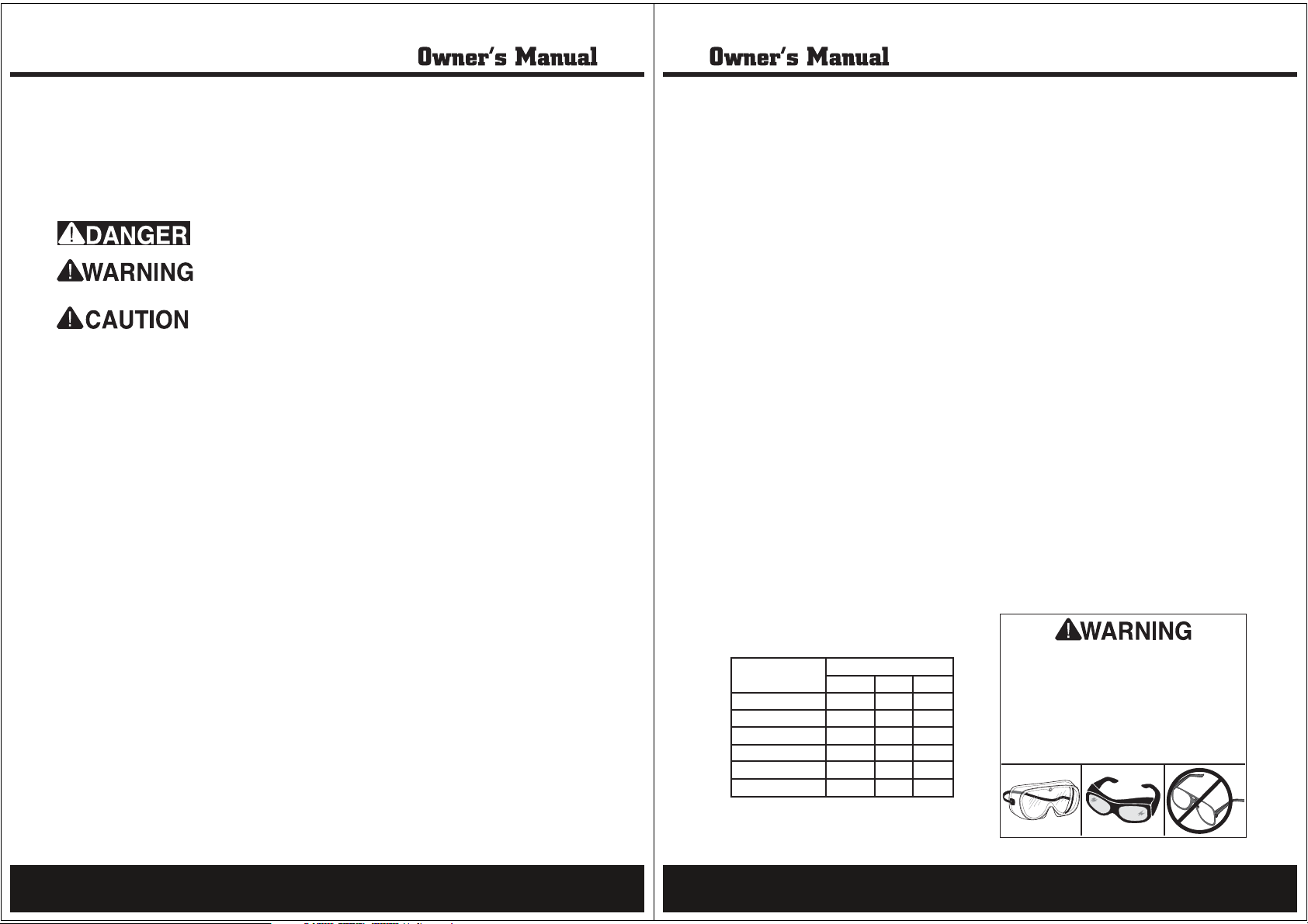
Extension Cord Requirements
Length And Gauge
Amp Rating 25ft 50ft 100ft
0-6 #16 #16 #16
7-10 #16 #16 #14
11-12 #16 #16 #14
13-16 #14 #12 #12
17-20 #12 #12 #10
21-30 #10 #10 No
Operating this equipment creates the
potential for flying debris to cause eye
injury. Always wear safety glasses or goggles when operating equipment. Everyday
glasses or reading glasses only have impact
resistant lenses, they are not safety glasses.
Be certain the safety glasses you wear meet
the appropriate standards of the American
National Standards Institute (ANSI).
5
6
Page 4
SAFETY
Know Your Machine
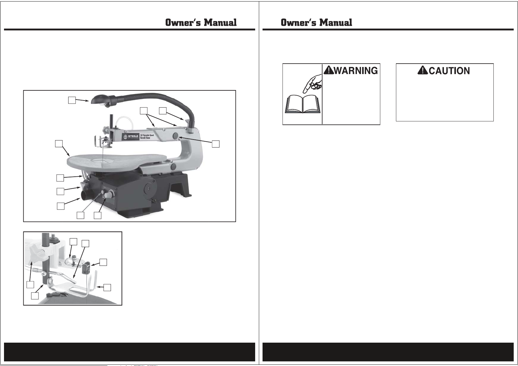
An important part of safety is knowing your machine and its components. Please take the time to
learn the items shown in the pictures below. The letters in the picture correspond to the following
descriptions in the list.
J
K
H
C
D
E
F
G
Q
P
O
L
M
N
A
B
A. Blade Tension Knob
B. Arm Bearing
C. Table Bevel Scale
D. Table Lock Knob
E. Dust Port
F. Light Button
G. Variable Speed/Power Knob
H. Table
J. Work Light
K. Blade Adapter Setting Position
L. Drop Foot Rod Lock Knob
M. Drop Foot Rod
N. Drop Foot
O. Blade Adapter (Mounted)
P. Sawdust Blower
Q. Upper Blade Holder
SAFETY
Safety Instructions for Your Scroll Saw
READ and understand this
entire instruction manual
before using this machine.
Serious personal injury
may occur if safety and
operational information is
not understood and followed. DO NOT risk your
safety by not reading!
1.SAW SAFETY BEGINS WITH YOUR LUMBER. Inspect your workpiece carefully before you feed it
into the saw. If you have any doubts about the stability or structural integrity of your workpiece,
DO NOT SAW IT!
2.AVOID AWKWARD OPERATIONS AND HAND POSITIONS where a sudden slip could cause your
hand to move into the blade. Always make sure you have good balance.
3.KEEP HANDS AWAY FROM CUTTING AREA. DO NOT hand hold pieces so small that your fingers
go under the blade guard. DO NOT reach underneath work or in blade cutting path with your hands
and fingers for any reason.
4.FIRMLY CLAMP OR BOLT your saw to a stable, level workbench or table. The best height is waist
level.
5.USE ONLY CORRECT BLADES. Use the correct blade size, style and cutting speed for the material
and type of cut.
6.ALWAYS SUPPORT LARGE WORKPIECES while cutting to minimize blade pinching and blade
breakage. The saw may slip, walk or slide when cutting large or heavy workpieces.
7.DO NOT REMOVE JAMMED CUT-OFF PIECES UNTIL THE BLADE HAS COME TO A COMPLETE STOP.
8.NEVER START THE SAW WHEN THE BLADE IS IN CONTACT WITH THE WORKPIECE.
9.BEFORE CHANGING THE SETUP, REMOVING COVERS, GUARDS OR BLADES,unplug the saw from
the power source and remove the switch safety key.
10.NEVER PERFORM CUTTING OPERATIONS WITH THE BLADE GUARD REMOVED.
11. BE AWARE THAT CERTAIN WOODS MAY CAUSE AN ALLERGIC REACTION in people and animals,
especially when exposed to fine dust. Make sure you know what type of wood dust you will be
exposed to and always wear an approved respirator.
Use this and other machinery with caution
and respect. Always consider safety first, as
it applies to your individual working conditions. No list of safety guidelines can be complete—every shop environment is different.
Failure to follow guidelines could result in
serious personal injury, damage to equipment or poor work results.
7
8
Page 5
ELECTRICITY
ELECTRICAL REQUIREMENTS
120V Operation
®
The STEELE
approximately 1.2 amps.
Since other machines may be using the same
circuit, make sure the circuit, circuit breaker,
or fuse can carry the total load without tripping.
If the total amperage load of all machines and
the scroll saw exceeds the amperage rating of
the circuit breaker or fuse, use a different circuit
that can carry the load.
DO NOT modify an existing low-amperage circuit
by only replacing the circuit breaker with a
breaker rated for a higher amperage. The breaker
and the complete circuit must be replaced by
a qualified electrician, otherwise the wires can
overheat and cause a fire.
If you must use an extension cord with the Model
SP-PB130, please follow these requirements:
•Use a cord rated for Standard Service
(Grade S).
•Use a 16 AWG cord that is 100 feet or less
•Use a cord with a ground pin
•Use an undamaged cord only
Model SP-PB130 motor draws
Extension Cords
Grounding
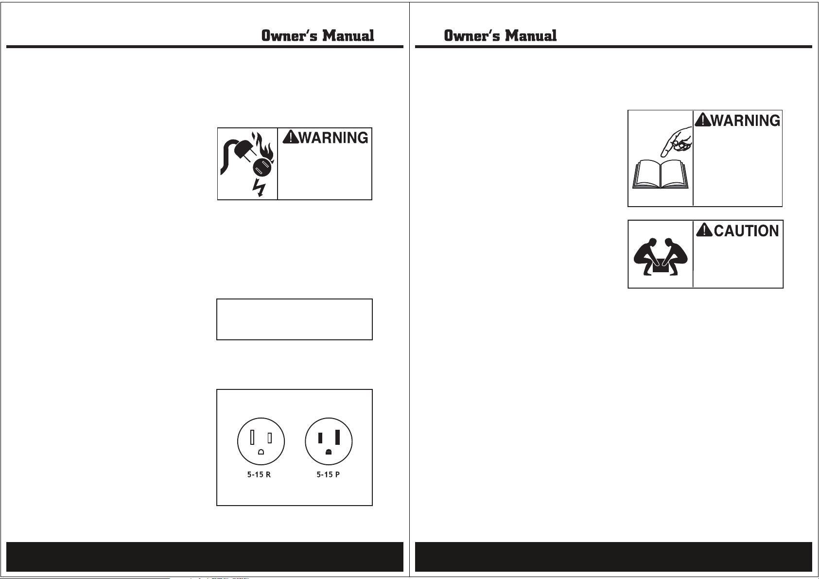
Serious injury or fire may
occur if you plug this
machine into a receptacle
that is not grounded.
Connect this machine to
grounded outlets only!
Ground this machine! The electrical cord supplied with the STEELE®Model SP-PB130 Scroll
saw has a three prong plug for grounded outlets.
See Figure 1. If your power receptacle does not
have a ground pin hole, have the receptacle
replaced by a qualified electrician, or have an
appropriate adapter installed and grounded
properly. NEVER cut the ground pin off so your
scroll saw will plug into a non-grounded receptacle.
NOTICE
When using an electrical plug adapter, make
sure the adapter is grounded.
Remember, an adapter with a grounding wire
does not guarantee the scroll saw is grounded.
A ground source must always be verified in the
electrical circuit within the wall or conduit.
ASSEMBLY
Unpacking
The Model SP-PB130 was carefully packed when
it left our warehouse.If you receive it damaged or
missing any parts, please contact Steele products
corp.Service and Support at 888-896-6881.
Inventory
Layout and inventory the package contents listed below and familiarize, yourself with the components shown in Figure 8 to ease assembly.
Item Qty.
1. Scroll Saw Unit.........................................1
2. 4mm Allen Wrench...................................1
3. 3mm T-Handle Allen Wrench....................1
4. Saw Blades...............................................2
5. Blade Guard..............................................1
6. Blade Adapters..........................................2
Read and understand this
entire instruction manual
before performing any
operations with your
machine. Serious personal
injury may occur if safety
and operational information is not understood and
followed.
The Model SP-PB130 is
a heavy machine at 27.5
lbs. Use assistance
when lifting or moving
the machine.
Figure 1.NEMA-style 5-15 plug and receptacle.
9
10
Page 6
ASSEMBLY
Shop Preparation
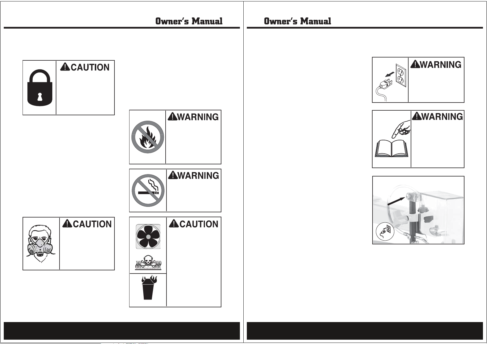
ONLY ALLOW TRAINED
PEOPLE in your shop! Make
sure shop entrances are
locked and machines are
correctly turned off with
lock-out devices when not
in use. Otherwise, injury
or death can occur.
Lighting:Lighting should be bright enough
to eliminate shadows and prevent eye
strain.
Working Clearances: Consider your current
and future shop needs with respect to the
safe operation of this machine.
Outlets: Make sure the electrical circuits
have the capacity to handle the amperage
requirements for your Model SP-PB130. Refer
to page 9 for more information. Electrical
outlets should be located near the lathe, so
power or extension cords are clear of hightraffic areas.
Dust Collection
Initial Cleaning
The exposed and unpainted scroll saw surfaces
are coated with a waxy oil to prevent rust during storage and shipment. DO NOT use chlorine
based solutions or solvents to remove the this
waxy oil, or you will damage the painted surfaces. Remove the waxy oil with a solvent based
degreaser before you use the scroll saw. Always
follow all usage and safety instructions of the
product that you are using.
DO NOT use flammables
such as gas or other
petroleum-based solvents
to clean your machine.
These products have low
flash points and present
the risk of explosion and
severe personal injury!
DO NOT smoke while
using cleaning solvents.
Smoking may cause
explosion or risk of fire
when exposed to these
products!
ASSEMBLY
Mounting Scroll Saw
The scroll saw can be mounted to a workbench
two ways:
• Permanent mounting can be accomplished
by bolting the base to the workbench.
Because workbench table thickness can
vary, fasteners have not been supplied.
• Temporary mounting can be accomplished
by securing the base of the scroll saw to a
3
piece of
21" x 14". The scroll saw/plywood assembly
can then be temporarily clamped to a workbench or other suitable working surface.
Vibration caused by operating the scroll saw can
be reduced by placing a foam pad or piece of
carpet between the saw base and the workbench.
To prepare the table surface for workpieces,
do these steps:
/4" plywood that measures at least
Table Prep
Blade Guard
UNPLUG POWER CORD
before you do any assembly or adjustment tasks!
Otherwise, serious personal injury to you or others may occur!
Read and understand this
entire instruction manual
before performing any
operations with your
machine. Serious personal
injury may occur if safety
and operational information is not understood and
followed.
THIS MACHINE produces
sawdust that may cause
allergic reactions or respiratory problems. Wear
a respirator in addition to
using a dust collection
system.
For information on the correct dust collection
components for the scroll saw, contact your
Steele products corp. dealers for a copy of the
Dust Collection Basics handbook and available
accessories.
11
ALWAYS work in a well
ventilated area when
using solvents with
fumes, and keep away
from any potential ignition sources (pilot
lights). Most solvents
used to clean machinery
are toxic when inhaled
or ingested. Always dispose of waste rags in a
sealed container to make
sure they do not cause
fire or environmental
hazards.
The blade guard must be installed before turning the scroll saw ON and before performing a
cutting operation.
To install the blade guard, do these steps:
1.
UNPLUG THE SCROLL SAW!
2. Using the supplied screw, nut, and washers,
install the clear blade guard onto the drop
foot rod ( Figure 2 ). Over-tightening the
bolt could break the clear plastic arms of
the blade guard.
3. Swing the blade guard up and down to
ensure that it moves smoothly.
Figure 2. Blade guard mounting location.
12
Page 7
ASSEMBLY
ASSEMBLY
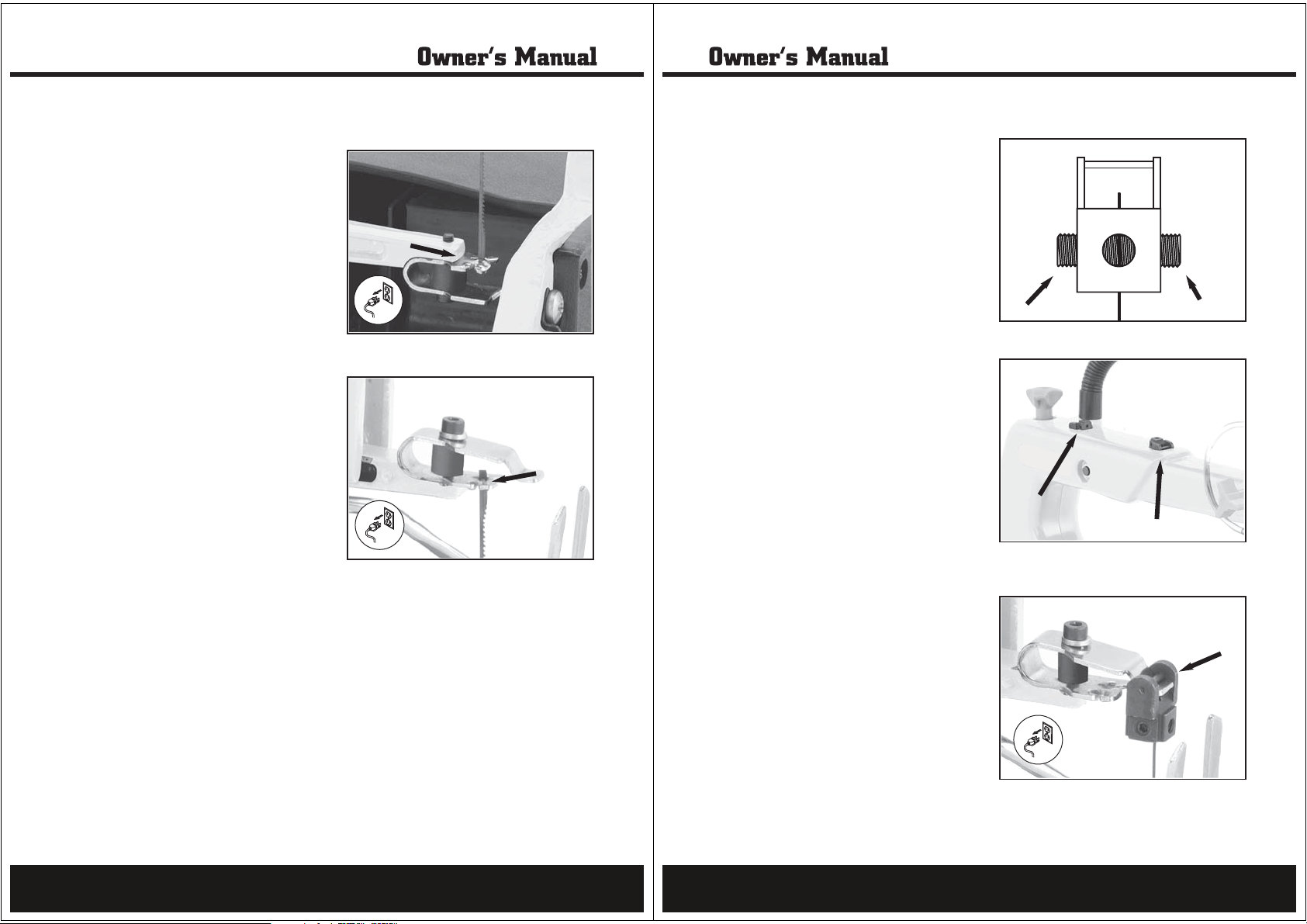
Installing Pin-End Blades
Scroll saw blades are classified as either “pin
end” or “plain end.” The blade included with
this saw is a pin end blade.
To install a pin end blade, do these steps:
1. UNPLUG THE SCROLL SAW!
2. Turn the tension adjustment knob counterclockwise to decrease the tension.
3. Remove the throat plate and slide the saw
blade down through the table insert hole so
the teeth face forward and down.
4. Slide the lower blade end through the Vnotch on the lower blade holder (Figure 3)
5. Press the upper blade holder downward and
slide the upper blade end through the Vnotch (Figure 4).
6. Turn the tension adjustment knob clockwise
to increase the blade tension to the desired
amount.
7. Replace the throat plate removed in step 3.
Figure 3. V-notch on lower blade holder.
Figure 4. V-notch on upper blade holder.
Installing Pain-End Blades
Using plain end blades requires the use of blade
adapters. The blade adapters attach to each end
of the saw blade, allowing plain end blade to be
installed on the upper and lower blade holders.
To install a plain end blade, do these steps:
1. UNPLUG THE SCROLL SAW!
2. Turn the tension adjustment knob counterclockwise to decrease the tension.
3. Loosen the setscrews (Figure 5) on the
blade adapters to allow the saw blade ends
to slide through the mounting holes. The
setscrews can be threaded into either set of
holes depending on whether side cutting or
straight cutting is desired.
4. Position the blade adapters in the gauge on
top of the scroll saw (Figure 6) to correctly
set the blade length.
5. TIghten the blade adapter setscrews to
securely position the blade in the center of
the mounting holes
6. Remove the throat plate and slide the saw
blade down through the table insert hole so
the teeth face forward and down.
7. Slide the lower blade adapter over the
mounting arm of the lower blade holder.
Then, press the upper blade holder downward and slide the upper blade adapter over
the mounting arm of the upper blade holder
(Figure 7).
Figure 5. Blade adapter setscrews.
Figure 6. Blade adapters in the gauge on top of
the scroll saw.
13
8. Turn the tension adjustment knob clockwise
to increase the blade tension to the desired
amount.
9. Replace the throat plate removed in step 6.
Figure 7. Blade adapter on the
upper blade holder.
14
Page 8
ASSEMBLY
ADJUSTMENTS
Drop Foot
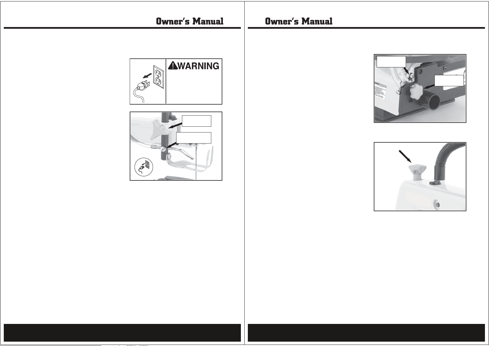
The drop foot must be adjusted to hold the
workpiece against the table during cutting operations. The front of the drop foot also acts as a
blade guard, preventing the operator’s fingers
from coming into contact with the blade.
To adjust the drop foot, do these steps:
1. Loosen the drop foot lock knob (Figure 8).
2. Adjust the drop foot so it makes contact
with the workpiece.
3. Retighten the drop foot lock knob.
The bottom face of the drop foot must always
be parallel to the top face of the table.
Sawdust Blower
The sawdust blower directs a current of air onto
the cut line, blowing the sawdust from the workpiece.
To adjust the sawdust blower, do these steps:
1. Loosen the phillips head screw on the side
of the drop foot rod (Figure 8).
2. Adjust the sawdust blower to the desired
position.
UNPLUG the power cord
before you do any assembly or adjustment tasks!
Otherwise, serious personal injury to you or others may occur!
Drop Foot
Lock Knob
Screw For Blower
Adjustment
Figure 8. Upper saw adjustments.
Scale Calibration
To calibrate the scale, do these steps:
1. Loosen the table lock knob (Figure 9).
2. Using a machinist’s square, adjust the table
square to the saw blade. Retighten the
table lock knob.
3. @FQOPPDA=JCHAO?=HALKEJPANPKPDA
mark (Figure 9).
4. Adjust the table stop bolt so it makes contact with the underside of the table.
The angle scale is only a rough scale and should
not be used to set the table for precise angle
cuts.
Blade Tension
Correct blade tension is essential to maximizing
the performance of the scroll saw. Blades that
are tensioned correctly will also last longer and
are less likely to break during a cutting operation; however, finding the correct amount of
tension for the saw blade is a subjective matter
that often results in trial-and-error adjustments.
Having too little tension on the blade is safer
than having too much. If the blade is tensioned
too tight, the blade could break, causing serious
personal injury. If the blade is tensioned too
loose, the blade will more than likely fall off
during the cutting operation.
Angle Scale
Pointer
Table Lock
Knob
Figure 9.Lower saw adjustments.
Figure 10.Blade tension knob.
15
To adjust the blade tension, do these steps:
Turn the blade tension knob (Figure 10)
clockwise to increase the blade tension.
Turn the blade tension knob counter-clock-
wise to decrease the blade tension.
Get into the habit of plucking the saw blade
every time the blade is replaced or re-installed.
With time and experience, a distinct sound will
be recognized as the “correct” blade tension.
16
Page 9
OPERATIONS
OPERATIONS
Test Run
Once assembly is complete, the machine is
ready for a test run. The purpose of a test run is
to identify any unusual noises and vibrations, as
well as to confirm that the machine is performing as intended.
To test run the Model SP-PB130,do these steps:
1. Make sure that all tools have been removed
from the scroll saw.
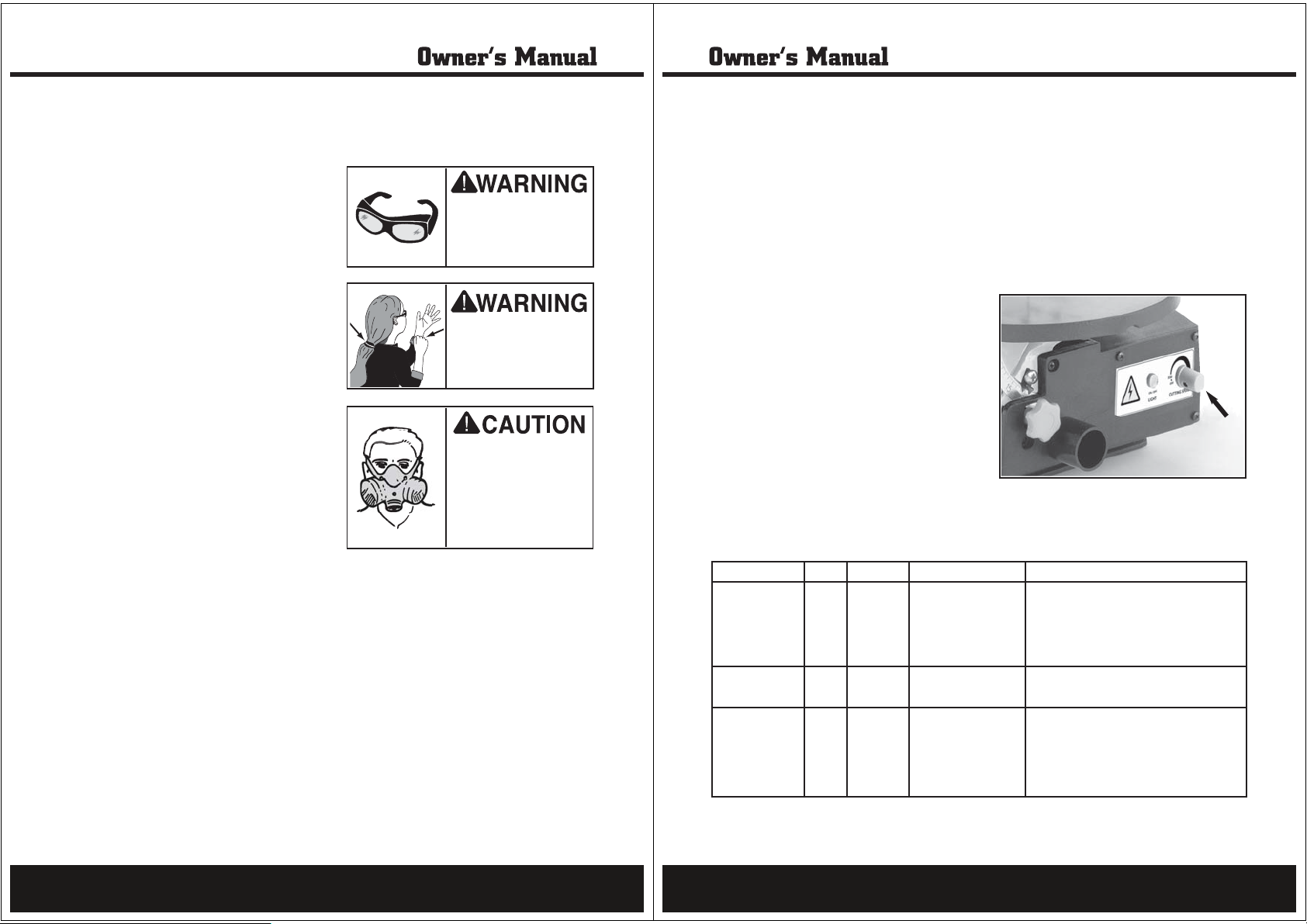
2. Turn the variable speed/power knob clockwise to turn the scroll saw ON.
3. Once the scroll saw is running, listen for any
unusual noises. The machine should run
smoothly with little or no vibrations.
• If there are any unusual noises or vibra-
tions, stop the scroll saw immediately by
pushing the paddle switch down.
4. Unplug the scroll saw and investigate the
source of the noise or vibration. DO NOT
make any adjustments to the scroll saw
while it is plugged in. The scroll saw should
not be run any further until the problems
are corrected.
THIS MACHINE throws
wood chips and sawdust.
Wear safety glasses or a
face shield during all
operations.
KEEP loose clothing
rolled up and out of the
way of machinery and
keep hair pulled back.
THIS MACHINE produces
sawdust that may cause
allergic reactions or respiratory problems. Wear
a respirator in addition
to using a dust collector.
Blade SpeedBlade Information
Important issues regarding blade perfor-
To change the blade speed:
mance:
The blade speed is variable between 550 and
• Scroll saw blades wear out and must be
replaced frequently. Typically a blade will
stay sharp anywhere from to 2 hours
1
2
depending on how the blade is used and
1700 strokes-per-minute (SPM). Blade speed
adjustments are made using the variable speed
/power knob(Figure 11)on the front of the
scroll saw.
what type of material is being cut.
• Best cutting results will be achieved when
cutting material less than 1" thick.
• When cutting material thicker than 1", use a
very slow feed rate.
• Blades will become dull quickly whenever
making cuts in plywood, hardwoods, and
laminates.
• Exerting excessive side pressure on the
blade greatly increases the chance of blade
breakage.
Figure 11. Variable speed/power knob.
Blade Selection Table
Teeth Per Inch Width Thickness Strokes-Per-Minute Material Being Cut
10 0.110" 0.020" 1200-1700 General purpose blade for cutting hard
and soft woods between
Also good for plastics, paper, felt, and
bone.
15 0.110" 0.020" 600-1200 Good for cutting very thin wood and
plastic between
18 0.095" 0.010" 500-600 Good for tight radius cutting in thin
hard and soft woods between
1
8".Also good for veneer, bone, ivory,
and plastics
3
3
" and
32
16
1
" and 2".
".
2
3
32
" and
17
18
Page 10
OPERATIONS
MAINTENANCE
To perform a standard scroll cutting operation:
For standard scroll cutting, follow the pattern
lines on the workpiece by pushing and turning
the workpiece at the same time. DO NOT turn
the workpiece without pushing it at the same
time; otherwise, the blade could twist and
break.
Interior Scroll CuttingStandard Scroll Cutting
The scroll saw can also make internal scroll cuts
without having to cut through the perimeter of
the workpiece.
To perform an interior scroll cutting operation:
1. UNPLUG THE SCROLL SAW!
2. Remove the saw blade.
3. Drill a
4. Place the hole in the workpiece over the
5. Re-install the blade by sliding the bottom
6. Adjust the drop foot onto the surface of the
7. Plug the scroll saw in and perform the cut-
8. When the cutting operation is complete,
1
/4" hole in the workpiece.
blade hole in the table insert.
end of the blade through the workpiece
hole. Note—If a plain end blade is being
used, the lower blade adapter may need to
be installed after the blade is slid through
the workpiece.
workpiece.
ting operation.
unplug the scroll saw and remove the saw
blade.
General
Regular periodic maintenance on your Model
SP-PB130 will ensure its optimum performance.
Make a habit of inspecting your machine each
time you use it. Check for the following conditions and repair or replace when necessary:
Loose mounting bolts.
Worn switch.
Worn or damaged cords and plugs.
Any other condition that could hamper the
safe operation of this machine.
Arm Bearings
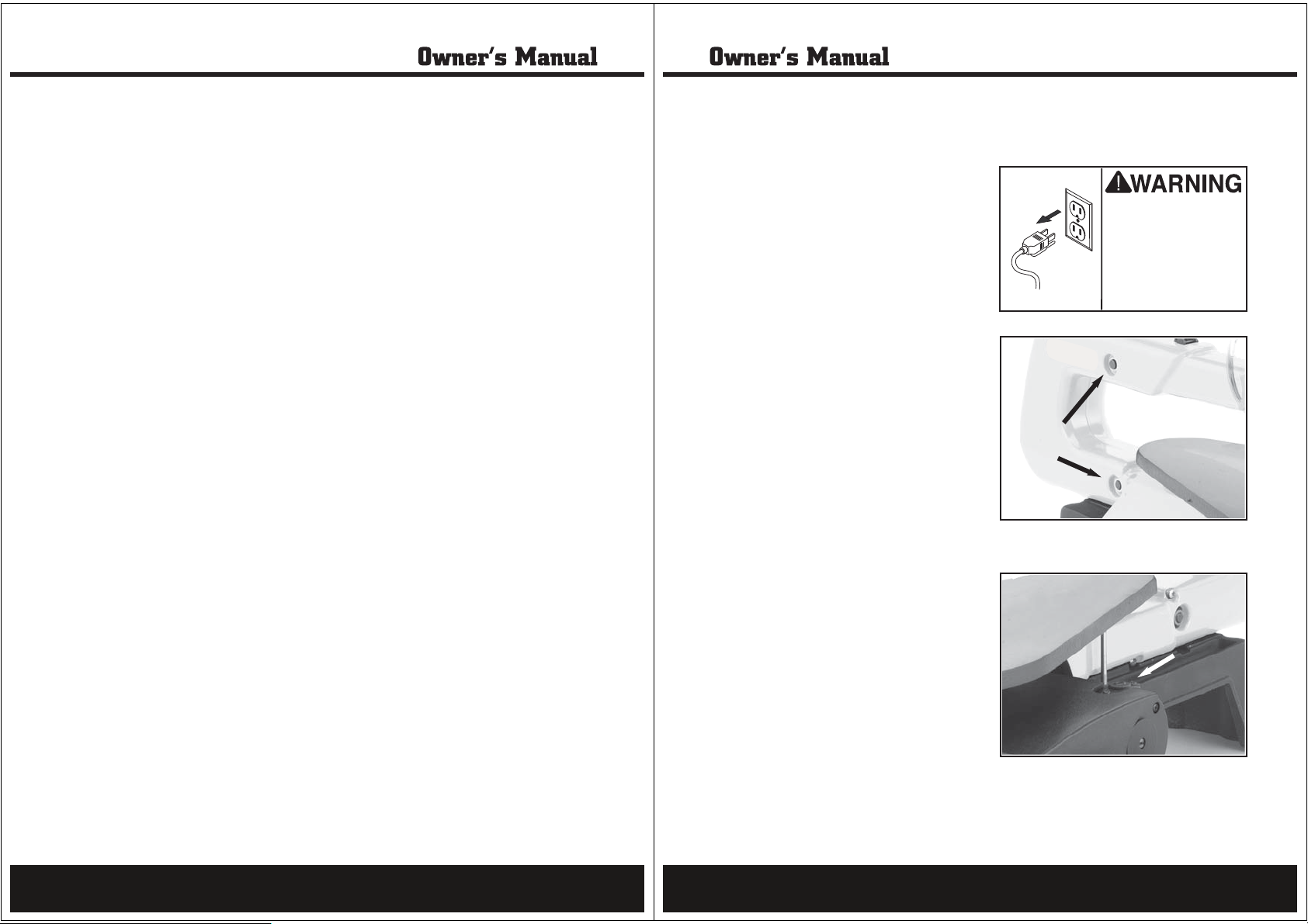
The arm bearings(Figure 12)on each side of the
scroll saw need to be lubricated after every 6-10
hours of use. Unplug the saw, lay it on its side,
and apply a generous amount of SAE 20 oil. Let
stand overnight. Perform the same procedure to
the opposite side bearings.
Motor Brushes
Make sure that your
machine is unplugged
during any maintenance
procedures except
where instructed otherwise! If this warning is
ignored, serious personal injury may occur.
Figure 12. Arm bearings.
19
To replace the motor brushes, do these steps:
1. Using a flat-head screwdriver, remove the
motor brush caps. The top cap is accessible
from the top of the scroll saw and the bottom cap is accessible through a hole on the
bottom of the base (Figure 13).
2. Replace the motor brushes if they are damaged or severely blackened by carbon buildup.
3. Re-install the motor brush caps.
Figure 13. Motor brush cap (1 of 2).
20
Page 11
Parts
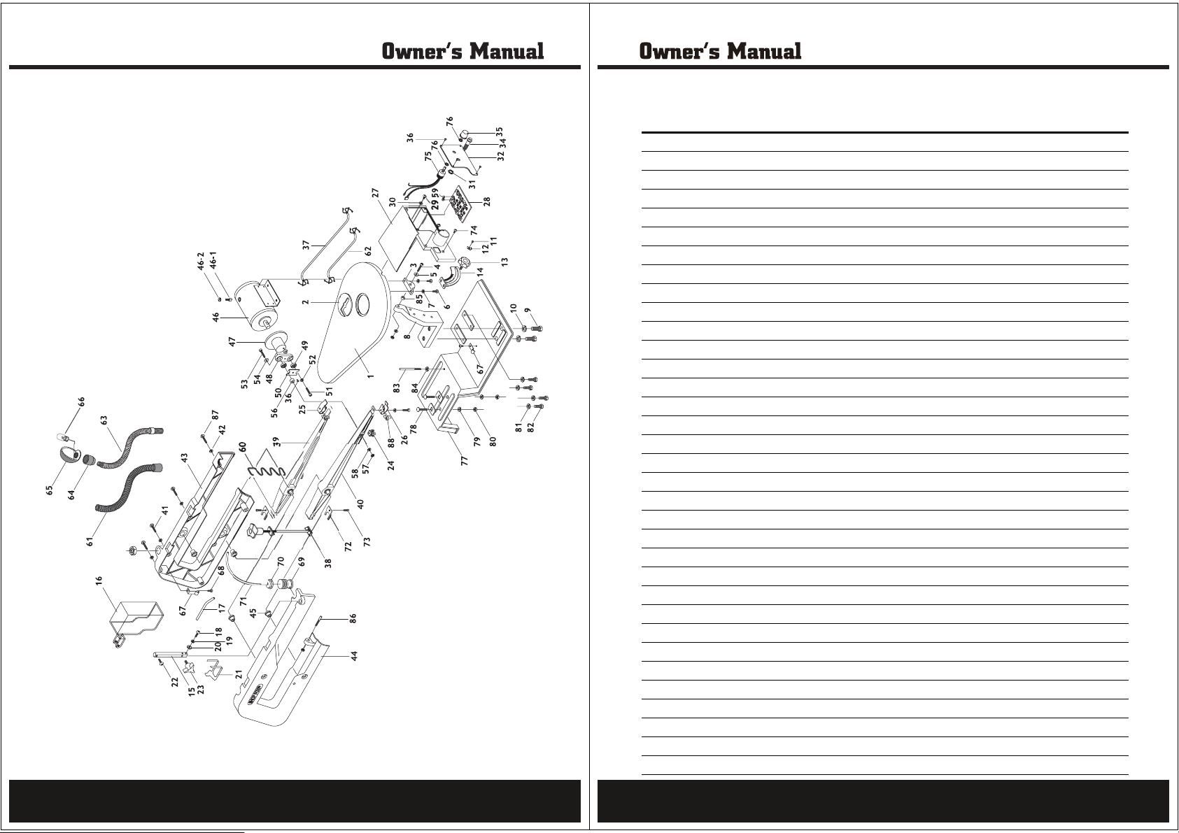
Parts Listing
APA Parts NO. Parts No. Description
PB130-01-AW 01 TABLE
PB130-02-AW 02 TABLE INSERT
PB130-03-AW 03 TABLE PIVOT BRACKET
PB130-04-AW 04 CAP SCREW M6-1 X 35
PB130-05-AW 05 FLAT WASHER 6MM
PB130-06-AW 06 PHLP HD SCR M5-8 X 10
PB130-07-AW 07 LOCK WASHER 5MM
PB130-08-AW 08 TABLE PEDESTAL
PB130-09-AW 09 HEX BOLT M8-1.25 X 25
PB130-10-AW 10 LOCK WASHER 8MM
PB130-11-AW 11 PHLP HD SCR M6-1 X 10
PB130-12-AW 12 SCALE INDICATOR
PB130-13-AW 13 MALE KNOB M6 X 14
PB130-14-AW 14 $/!21"!0 )"
PB130-15-AW 15 AIR HOSE POST
PB130-16-AW 16 BLADE GUARD
PB130-17-AW 17 AIR HOSE
PB130-18-AW 18 PHLP HD SCR M6-1 X 10
PB130-19-AW 19 LOCK WASHER 6MM
PB130-20-AW 20 FLAT WASHER 6MM
PB130-21-AW 21 HOLD DOWN SHOE
PB130-22-AW 22 PHLP HD SCR M5-8 X 10
PB130-23-AW 23 KNOB BOLT M6-1 X 13
PB130-24-AW 24 BLADE CLAMP
PB130-25-AW 25 UPPER BLADE GUIDE
PB130-26-AW 26 LOWER BLADE GUIDE
PB130-27-AW 27 SWITCH BOX HOUSING
PB130-28-AW 28 CIRCUIT BOARD
PB130-29-AW 29 MPHLP HD SCR M4-7 X 12
PB130-30-AW 30 FLAT WASHER 4MM
PB130-31-AW 31 HEX NUT M12-1.75
PB130-32-AW 32 LOCK WASHER 12MM
PB130-33-AW 33 SWITCH BOX COVER
PB130-34-AW 34 LIGHT SWITCH
21
22
Page 12
Parts Listing
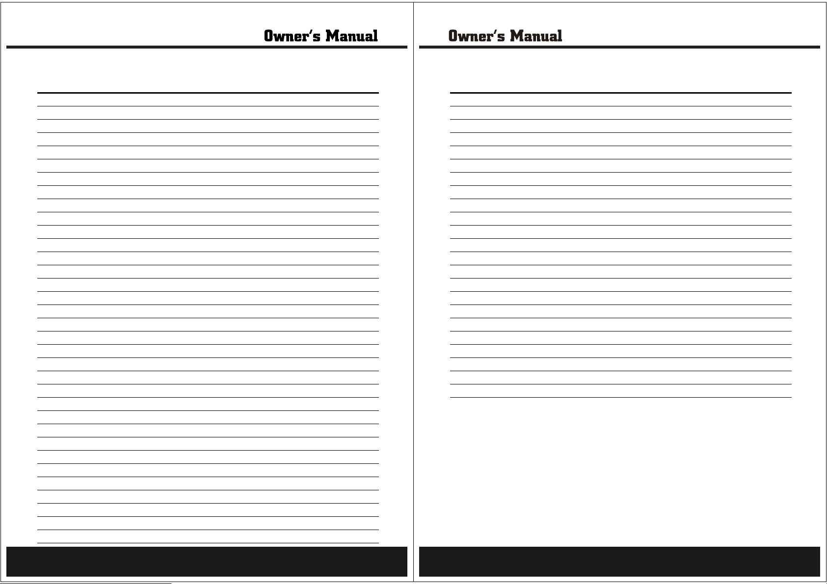
Parts Listing
APA Parts NO. Parts No. Description
PB130-35-AW 35 SPEED CONTROL DIAL
PB130-36-AW 36 TAP SCREW #8 X 3/8"
PB130-37-AW 37 POWER CORD
PB130-38-AW 38 BLADE TENSION ASSEMBLY
PB130-39-AW 39 UPPER ARM
PB130-40-AW 40 LOWER ARM
PB130-41-AW 41 PHLP HD SCR M5-8 X 35
PB130-42-AW 42 LOCK WASHER 5MM
PB130-43-AW 43 RIGHT ARM COVER
PB130-44-AW 44 LEFT ARM COVER
PB130-45-AW 45 BUSHING 3/8"
PB130-46-AW 46 MOTOR
PB130-47-AW 47 CARBON BRUSH
PB130-48-AW 48 CARBON BRUSH CAP
PB130-49-AW 49 FLYWHEEL
PB130-50-AW 50 LINK
PB130-51-AW 51 BALL BEARING 625ZZ
PB130-52-AW 52 RETAINER
PB130-53-AW 53 CAP SCREW M5-8 X 16
PB130-54-AW 54 LOCK WASHER 5MM
PB130-55-AW 55 CAP SCREW M5-8 X 25
PB130-56-AW 56 FLAT WASHER 5MM
PB130-57-AW 57 LOCK WASHER 4MM
PB130-58-AW 58 SPACER 5MM ID X 6MM
PB130-59-AW 59 HEX NUT M5-8
PB130-60-AW 60 6 AMP FUSE
PB130-61-AW 61 FLEXIBLE NECK GUARD
PB130-62-AW 62 FLEXIBLE NECK
PB130-63-AW 63 LAMP HOUSING
PB130-64-AW 64 LAMP
PB130-65-AW 66 BULB
PB130-67-AW 67 CORD CLAMP
PB130-69-AW 68 PHLP HD SCR M4-7 X 8
PB130-69-AW 69 BELLOWS
APA Parts NO. Parts No. Description
PB130-70-AW 70 BELLOWS LOCK
PB130-71-AW 71 PVC TUBE
PB130-72-AW 72 FORKED RETAINER
PB130-73-AW 73 CAP SCREW M4-7 X 10
PB130-74-AW 74 PHLP HD SCR M5-8 X 8
PB130-75-AW 75 VARIABLE SPEED SWITCH
PB130-76-AW 76 THIN PROFILE HEX NUT 10MM
PB130-77-AW 77 BASE
PB130-78-AW 78 CARRIAGE BOLT M6-1 X 20
PB130-79-AW 79 LOCK WASHER 6MM
PB130-80-AW 80 HEX NUT M6-1
PB130-81-AW 81 LOCK WASHER 6MM
PB130-82-AW 82 HEX BOLT M6-1 X 20
PB130-83-AW 83 STUD BOLT M6-1 X 95
PB130-84-AW 84 HEX NUT M6-1
PB130-85-AW 85 SPACER
PB130-86-AW 86 STUD BOLT HINGE PIN M6-1 X 18
PB130-87-AW 87 PHLP HD SCR M6-1 X 30
PB130-88-AW 88 BLADE GUIDE SPACER
23
24
Page 13
Limited Warranty
Steele® warrants to the original purchaser who uses the product in a consumer application (personal,
residential or household usage) that all products covered under this warranty are free from defects in
material and workmanship for one year from the date of purchase. All products covered by this limited
warranty which are used in commercial applications (i.e. income producing) are warranted to be free of
defects in material and workmanship for 90 days from the date of original purchase. Products covered under
this warranty include air compressors, tools, service parts, pressure washers and generators.
Steele® will repair or replace, at Steele®’s sole option, products or components which have failed within the
warranty period. Service will be scheduled according to the normal work flow and business hours at the
service center location, and the availability of replacement parts. All decisions of Steele® with regard to this
limited warranty shall be final.
This warranty gives you specific legal rights, and you may also have other rights which vary from state to
state.
RESPONSIBILITY OF ORIGINAL PURCHASER (initial User):
To process a warranty claim on this product, DO NOT return item to the retailer. The product must be
evaluated by an Authorized Warranty Service Center. For the location of the nearest Authorized Warranty
Service Center contact the retailer or place of purchase.
Retain original cash register sales receipt as proof of purchase for warranty to work.
Merchandise sold by Steele® which has been manufactured by and identified as the product of another
company, such as gasoline engines. The product manufacturer’s warranty, if any, will apply.
ANY INCIDENTAL, INDIRECT OR CONSEQUENTIAL LOSS, DAMAGE, OR EXPENSE THAT MAY RESULT
FROM ANY DEFECTS, FAILURE OR MALFUNCTION OF THE PRODUCT IS NOT COVERED BY THIS
WARRANTY. Some states do not allow the exclusion, so it may not apply to you.
IMPLIED WARRANTIES, INCLUDING THOSE OF MERCHANTABILITY OR FITNESS FOR A PARTICULAR
PURPOSE, ARE LIMITED TO ONE YEAR FROM THE DATE OF ORIGINAL PURCHASE. Some states do not
allow limitations on how long an implied warranty lasts, so the above limitations may not apply to you.
Use reasonabl
Deliver or ship the product to the Authorized Warranty Service Center. Freight costs, if any must be paid by
the purchaser. If the purchaser does not receive satisfactory results form the Authorized Warranty Service
Center, the purchaser should contact Steele® toll free 888-896-6881.
THIS WARRANTY DOES NOT COVER:
Merchandise sold as reconditioned, used as rental equipment, or floor or dis
Merchandise that has become damaged or inoperative because of ordinary wear, misuse, cold, heat, rain,
excessive humidity, freeze damage, use of improper chemicals, negligence, accident, failure to operate the
product in accordance with the instructions provided in the Owner’s Manual(s) supplied with the product,
improper maintenance, the use of accessories or attachments not recommended by Steele®, or
unauthorized repair or alterations.
Repair and transportation costs of
Costs associated with assembly, required oil, adjustments or other installation and start-up costs.
Expendable parts or accessories supplied with the product which are expected to become inoperative or
unusable after a reasonable period of use.
e care in the operation and maintenance of the product as described in the Owner’s Manual(s).
play models.
merchandise determine not to be defective.
25
Distributed by:
730 S.Epperson Dr.
City Of Industry,CA91748
www.steele-products.com
all rights reserved
26
 Loading...