

Page 1
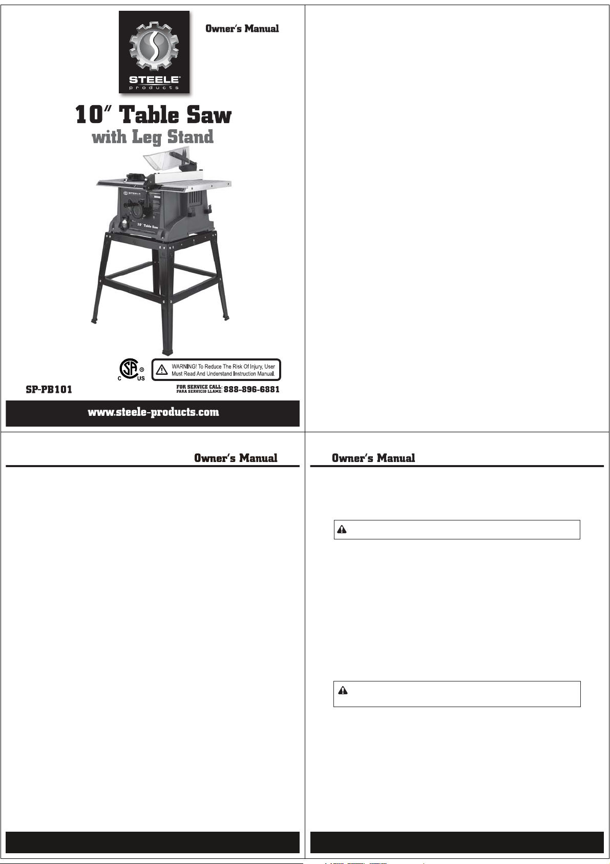
230181
Model:72551
Table of Contents
Technical data . . . . . . . . . . . . . . . . . . . . . . . . . . . . . . . . . . . . . . . . . . . . .
General safety rules . . . . . . . . . . . . . . . . . . . . . . . . . . . . . . . . . . . . . . . . .
Specific safety rules for the table saw . . . . . . . . . . . . . . . . . . . . . . . . . . .
Electrical information . . . . . . . . . . . . . . . . . . . . . . . . . . . . . . . . . . . . . . .
Know your table saw . . . . . . . . . . . . . . . . . . . . . . . . . . . . . . . . . . . . . . .
Assembly and adjustments . . . . . . . . . . . . . . . . . . . . . . . . . . . . . . . . . .
Operation . . . . . . . . . . . . . . . . . . . . . . . . . . . . . . . . . . . . . . . . . . . . . . .
Maintenance . . . . . . . . . . . . . . . . . . . . . . . . . . . . . . . . . . . . . . . . . . . . . .
Troubleshooting . . . . . . . . . . . . . . . . . . . . . . . . . . . . . . . . . . . . . . . . . . .
Replacement parts . . . . . . . . . . . . . . . . . . . . . . . . . . . . . . . . . . . . . . . . .
Push stick pattern . . . . . . . . . . . . . . . . . . . . . . . . . . . . . . . . . . . . . . . . .
Warranty . . . . . . . . . . . . . . . . . . . . . . . . . . . . . . . . . . . . . . . . . . . . . . . .
Push stick pattern . . . . . . . . . . . . . . . . . . . . . . . . . . . . . . . . . . . . . . . . .
Technical data
Motor : 120V, 15A, 60Hz
Motor speed : 5000RPM (no load)
Overload protection : Yes
Table size : 16” x 26” (406 x 660mm)
Blade 10” (254mmcarbide-tipped;
5/8” (15.9mmarbor
Maximum depth of cut at 90° : 3” (76.2mm)
Maximum depth of cut at 45° : 2-1/2” (63.5mm)
Maximum width of dado : 1/2” (12.7mm)
Net weight : 50lb (23kg)
10
20
26
28
29
30
32
34
General safety rules
2
3
5
7
9
Safety is a combination of common sense, staying alert and knowing how your table saw works.
SAVE THE SESAFETY INSTRUCTIONS.
WARNING: To avoid mistakes that could cause serious injury, do not plug in the table saw
until the following steps have been read and understood.
1.READ and become familiar with this entire instruction manual. LEARN the tool’s applications,
limitations, and possible hazards.
2.AVOID DANGEROUS CONDITIONS. Do not use power tools in wet or damp areas or expose them
to rain. Keep work areas well-lit.
3.DO NOT use power tools in the presence of flammable liquids or gases.
4.ALWAYS keep your work area clean, uncluttered, and well-lit. DO NOT work on floor surfaces that
are slippery with sawdust or wax.
5.KEEP BYSTANDERS AT A SAFE DISTANCE from the work area, especially when the tool is
operating.NEVER allow children or pets near the tool.
6.DO NOT FORCE THE TOOL to do a job for which it was not designed.
7.DRESS FOR SAFETY. Do not wear loose clothing, gloves, neckties, or jewelry (rings,watches, etc.)
when operating the tool. Inappropriate clothing and items can get caught in moving parts and draw
you in. ALWAYS wear non-slip footwear and tie back long hair.
8.WEAR A FACE MASK OR DUST MASK as the sawing operation produces dust.
WARNING: Dust generated from certain materials can be hazardous to your health. Always
operate the saw in a well-ventilated area and provide for proper dust removal. Use dust
collection systems whenever possible.
9.ALWAYS remove the power cord plug from the electrical outlet when making adjustments, changing
parts, cleaning or working on the tool.
10.KEEP GUARDS IN PLACE AND IN WORKING ORDER.
11.AVOID ACCIDENTAL START-UPS. Make sure the power switch is in the OFF position before plugging
in the power cord.
12.REMOVE ADJUSTMENT TOOLS. Always make sure all adjustment tools are removed from the saw
before turning it on.
13.NEVER LEAVE ARUNNING TOOL UNATTENDED. Turn the power switch to OFF. Do not leave the
tool until it has come to a complete stop.
2
3
Page 2
General safety rules (continued)
01.Always use the splitter and anti-kickback pawls for all operations, including through-sawing.
Through-sawing operations are those in which the blade cuts completely through the
workpiece when ripping or cross-cutting.
02.Always hold the workpiece firmly against the miter gauge or rip fence.
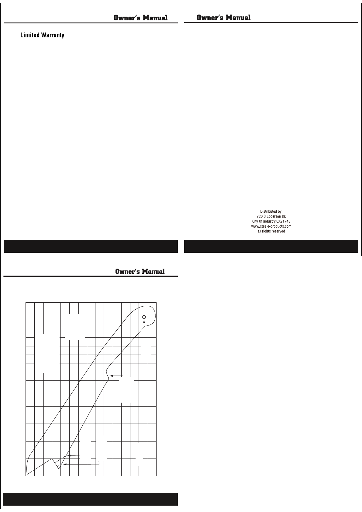
03.Use a push stick when required. Always use a push stick for ripping narrow stock. Refer to ripping
applications in the instruction manual where the push stick is covered in detail. See the push stick
pattern included in this instruction manual.
04.Never perform any operation“free hand”(using only your hands to support or guide the workpiece).
Always use either the fence or the miter gauge to position and guide the work.
05.Never stand or place any part of your body in line with the path of the saw blade. Keep your hands
out of the line of the saw blade.
06.Never reach behind or over the table saw.
07.Remove the rip fence when cross-cutting.
08.Feed the workpiece into the blade against the direction of rotation only.
09.Never use the fence as a cut-off gauge when cross-cutting.
10.Never attempt to free a stalled saw blade without first turning the saw OFF. Turn off the power
switch immediately to prevent motor damage.
11.Provide adequate support to the rear and sides of the saw table for wide or long workpieces.
12.Avoid kickbacks (work thrown back toward you) by keeping the blade sharp, keeping the rip fence
parallel to the saw blade, and keeping the splitter, anti-kickback pawls, and guard inplace and
operating.Do not release work before it is pushed all the way past the saw blade. Do not rip work
that is twisted, warped, or does not have a straight edge to guide along the fence.
13.Avoid awkward operations and hand positions where a sudden slip could put your hand in the
cutting path.
WARNING:
Do not operate the table saw until it is completely assembled and installed
according to the instructions.
Specific safety rules for the table saw
5
14.NEVER STAND ON A TOOL. Serious injury could result if the tool tips or is accidentally hit.DO NOT
store anything above or near the tool.
15.DO NOT OVER REACH. Keep proper footing and balance at all times. Wear oil-resistant rubbersoled footwear. Keep the floor clear of oil, scrap, and other debris.
16.MAINTAIN TOOLS PROPERLY. ALWAYS keep tools clean and in good working order. Follow
instructions for lubricating and changing accessories.
17.CHECK FOR DAMAGED PARTS. Check for alignment of moving parts, jamming, breakage,
improper mounting, or any other conditions that may affect the tool’s operation. Any part that
is damaged should be properly repaired or replaced before use.
18.MAKE THE WORKSHOP CHILDPROOF. Use padlocks and master switches and ALWAYS
remove starter keys.
19.DO NOT operate the tool if you are under the influence of drugs, alcohol, or medication that could
affect your ability to use the tool properly.
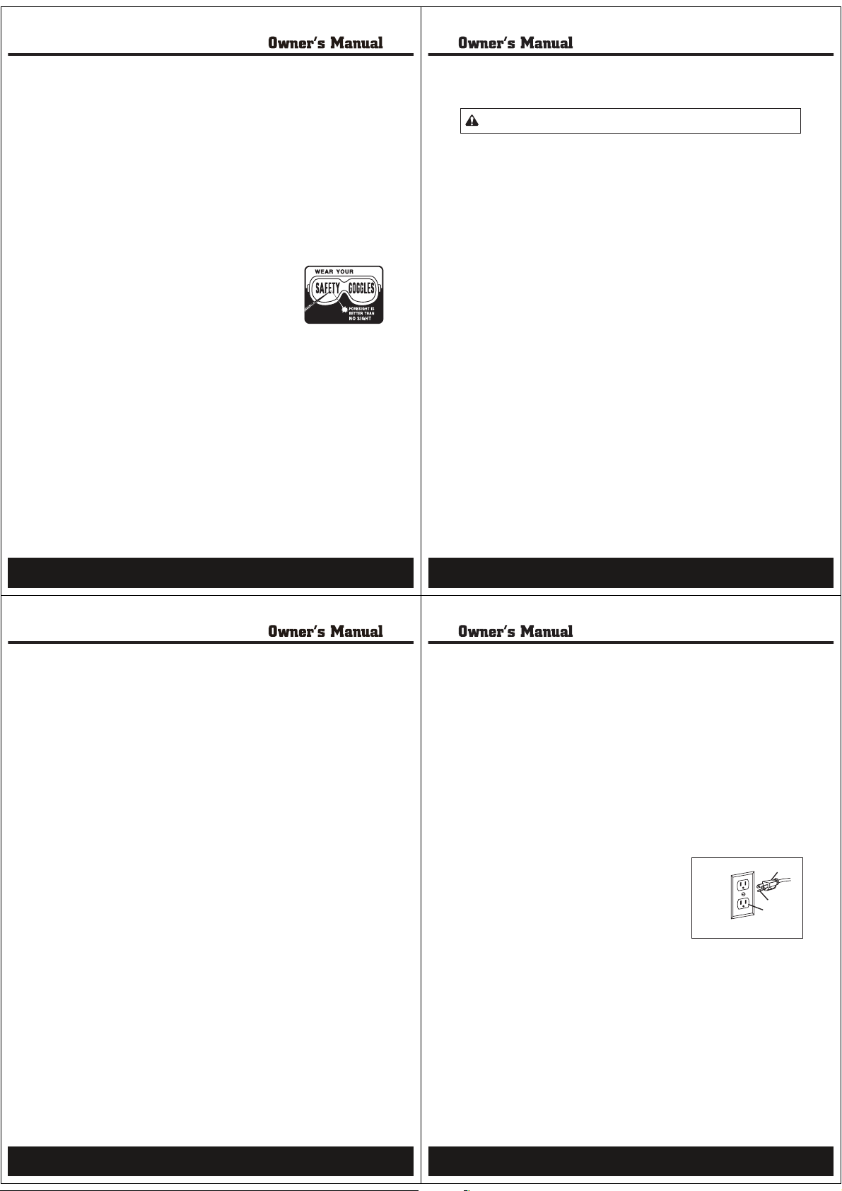
20.USE SAFETY GOGGLES AT ALLTIMES—that comply with ANSI Z87.1.
Normal safety glasses only have impact resistant lenses and are not
designed for safety. Wear a face or dust mask when working in a dusty
environment. Use ear protection, such as plugs or muffs, during
extended periods of operation.
4
Specific safety rules for the table saw (continued)
14.Never use solvents to clean plastic parts. Solvents could dissolve or otherwise damage the
material. Use only a soft damp cloth to clean plastic parts.
15.Never cut metals or materials which may create hazardous dust.
16.Always use in a well-ventilated area. Remove sawdust frequently. Clean out sawdust from the
interior of the saw to prevent a possible fire hazard.
17.To operate properly, this saw must be mounted on the leg stand or on a suitable work surface.
Failure to provide a sawdust fall-through and removal hole will allow sawdust to build up in the
motor area, which is a fire hazard and may cause motor damage.
18.Make sure there are no nails or foreign objects in the part of the workpiece to be cut.
19.Make sure there is no debris between the workpiece and its supports.
20.Use only sharp, clean blades with properly set teeth.
21.Do not use the saw without the proper blade insert.
Electrical information
Grounding Instructions
IN THE EVENT OF AMALFUNCTION OR BREAKDOWN,grounding provides the path of least resistance
for electric current and reduces the risk of electric shock. This tool is equipped withan electric cord
that has an equipment grounding conductor and a grounding plug. The plug MUST be plugged into a
matching outlet that is properly installed and grounded in accordance with ALL local codes and
ordinances.
DO NOT MODIFY THE PLUG PROVIDED. If it will not fit the outlet, have the proper outlet installed by
an electrician.
IMPROPER CONNECTION of the equipment grounding conductor can result in electric shock. The
conductor with the green insulation (with or without yellow stripes) is the equipment grounding
conductor. If repair or replacement of the electric cord or plug is necessary, DO NOT connect the
equipment grounding conductor to a live terminal.
CHECK with a licensed electrician or service personnel if you do not completely understand
thegrounding instructions, or if you are not sure if the tool is properly grounded.
USE ONLY THREE-WIRE EXTENSION CORDS that have 3-pronged
plugs and outlets that accept the tool's plug as shown in Fig. A.
Repair or replace a damaged or worn cord immediately.
CAUTION: In all case, make certain the outlet in question is properly grounded. If you are not sure
if it is, have a licensed electrician check the outlet.
Fig. A
1. 3-pronged plug 2. Properly grounded outlet
3. Grounding prong
1
3
2
6
7
Page 3
Electrical information (continued)
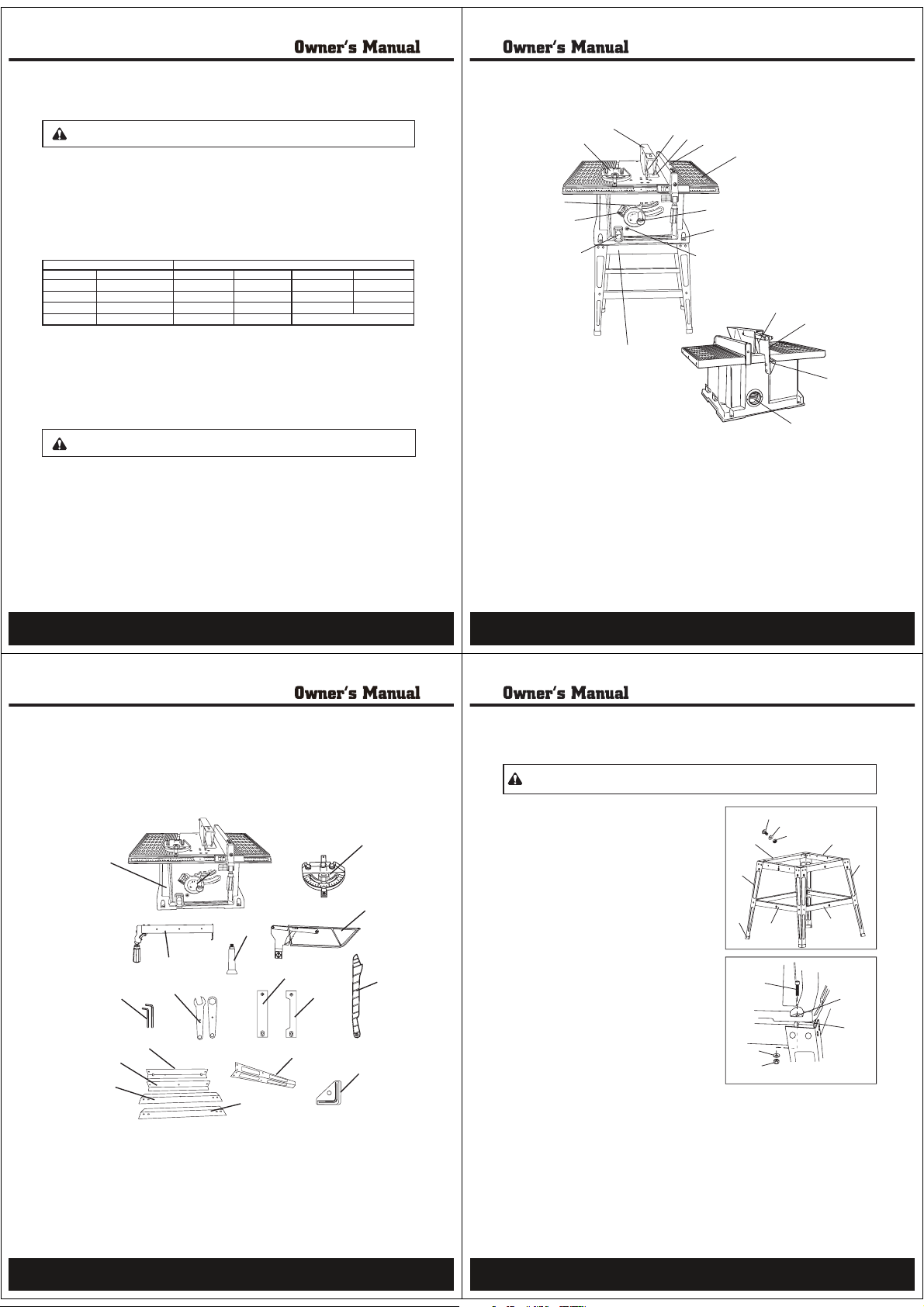
A Sliding miter gauge
B Blade guard
C Blade
D Table insert
E Rip fence
F Table
G Blade elevation/tilting control
wheel
H Base
I Overload reset switch
J ON/OFF switch with safety key
K Blade bevel scale
L Blade bevel lock knob
M Anti-kickback pawl
N Splitter bracket
O Sawdust port
P Splitter
Q Leg stand
N
O
Q
P
M
G
I
J
K
L
A
B
C
D
E
F
H
Know your table saw
9
WARNING: This table saw is for indoor use only. Do not expose to rain or use in damp
locations.
Guidelines for using extension cords
Make sure your extension cord is in good condition. When using an extension cord, be sure to use
one heavy enough to carry the current your product will draw. An undersized cord will cause a drop
in line voltage resulting in loss of power and overheating. The table below shows the correct size to
be used according to cord length and nameplate ampere rating. If in doubt, use the next heavier
gauge. The smaller the gauge number, the heavier the cord.
Minimum Gauge for Extension Cords (AWG)
(when using 120 V only)
More Than Not More Than 25 (7.6) 50 (15) 100 (30.4) 150 (45.7)
0 6 18 16 16 14
6 10 18 161412
10 12 16 16 14 12
12 16 14 12 Not Recommended
Be sure your extension cord is properly wired and in good condition. Always replace a damaged
extension cord or have it repaired by a qualified person before using it.
Protect your extension cords from sharp objects, excessive heat and damp or wet areas.
Use a separate electrical circuit for your tools. This circuit must not be less than a #12 wire and
should be protected with a 15 Atime-delayed fuse. Before connecting the motor to the power line,
make sure the switch is in the OFF position and the electric current is rated the same as the current
stamped on the motor nameplate. Running at a lower voltage will damage the motor.
WARNING: This tool must be grounded while in use to protect the operator from
electricshock.
Total Length of Cord in feet (meters)Ampere Rating
8
Assembly and adjustments
Unpacking (Fig. 1)
Carefully unpack the table saw and all its parts, and compare against the list below. Do not discard
the carton or any packaging until the miter saw is completely assembled.
Fig. 1
A Table saw assembly
B Miter gauge
C Rip fence and handle
D Blade elevation wheel handle
E Blade guard assembly
F Allen wrench (2)
A
F
L
K
N
4
D
C
G
M
G Blade wrenches
H Table insert
I Dado table insert
J Push stick
K Long top plates (2)
L Short top plates (2)
H
I
O
M Long support plates (2)
N Short support plates (2)
O Legs (4)
P Rubber feet (4)
Q Hardware kit (not shown)
B
E
J
P
Assembly and adjustments (continued)
WARNING: To avoid injury from an accidental start, make sure the power switch is in the
OFF position and the plug is not connected to the power source outlet.
Assembly
Assembling the leg stand (Fig. 2)
Note: Use the screws (1), washers (2) , and lock nuts (3)
supplied in the hardware kit to attach the pieces of
the leg stand together. Do not tighten the hardware
completely until the leg stand is assembled.
1.Attach the short top plates (4) to the legs (6).
2.Attach the short support plates (7) to the legs (6).
3.Place the long top plates (5) over the short top plates
(4). Attach the long top plates (5) to the legs (6).
4.Attach the long support plates (8) to the legs (6).
5.Tap the four rubber feet (9) onto the bottom of
the legs (6).
Mounting the table saw to the leg stand (Fig.3)
Note: Mount the table saw to the leg stand using the
hardware supplied in the hardware kit.
1.Place the table saw onto the assembled leg stand so
that the four mounting holes (1) in the base of the
saw are over the four mounting slots in the two long
top plates (2).
2.Secure the table saw to the leg stand using the four
internal screws (3) washers (4), and lock nuts (5)
supplied in the hardware kit.
IMPORTANT! When mounting the table saw to the leg
stand, DO NOT overtighten the mounting hardware.
1
2
3
5
6
9
7
3
4
5
Fig. 2
4
6
8
Fig. 3
1
2
10
11
Page 4
Assembly and adjustments (continued)
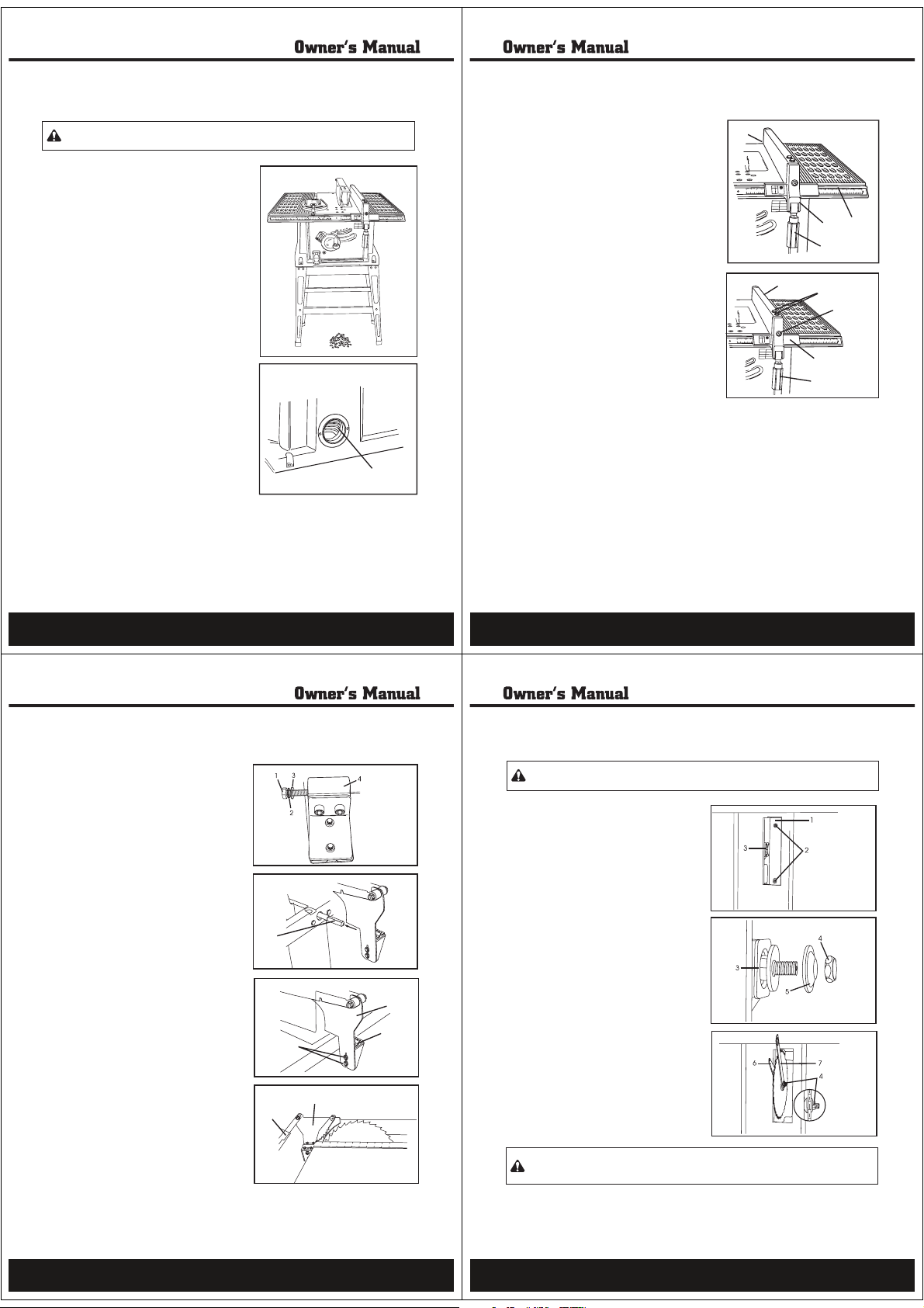
Front and rear locking rip fence (Fig.6)
1.Thread the fence handle (1) into the cam hole (2)
until tight.
2.Lift upward on the rip fence handle (1) so that the
holding clamp (3) is fully extended.
3.Place the rip fence on the saw table and engage the
holding clamp (3) to the rear of the table. Lower the
front end onto the front rail (4).
4.Push down on the fence handle (1) to lock.
Rip fence adjustment (Fig. 7)
1.To move the fence, pull the handle (2) up and slide
the fence (1) to the desired location. Push down on
the handle (2) to lock the fence in position.
2.Position the fence on the right side of the table and
along one edge of the miter gauge grooves.
3.Lock the fence handle (2). The fence should be parallel
to the miter gauge groove.
If adjustment is needed to make the fence parallel to the
groove, do the following:
4.Loosen the two screws
(3)
and lift up on the
handle (2).
5.Hold the fence bracket (4) firmly against the front of
the saw table. Move the far end of the fence until it is
parallel with the miter gauge groove.
6.Tighten both screws (3) and push the handle (2) down to lock.
7.If the fence is loose when the handle is in the locked (downward) position,move the handle (2)
upward and turn the adjusting screw
(5) clockwise until the rear clamp is snug.Do not turn the
adjusting screw
(5) more than 1/4 turn at a time.
Note: Over-tightening the adjusting screw (5) will cause the fence to come out of alignment.
1
10
23
4
2
2
2
2
2
30
23
2
2
21
22
24
1
1
10
4
2
3
1
Fig. 6
1
10
23
4
2
2
2
2
2
30
23
2
2
21
22
24
11
10
Fig. 7
1
4
2
3
5
Assembly and adjustments (continued)
13
Always keep the work area clean, uncluttered, and well lit. Do not work on floor
WARNING:
surfaces that are slippery.
Keeping the area clean (Fig. 4)
Sawdust and wood chips that fall under the saw
will accumulate on the floor. Make it a practice to
pick up and discard this dust when you have
completed cutting.
Sawdust port (Fig. 5)
The sawdust port (1) is located at the rear of the
saw. A dust collection system can be attached to
this port to aid in the removal of sawdust from the
work area.
Fig. 4
Fig. 5
1
12
Assembly and adjustments (continued)
Blade guard assembly (Fig. 8–11)
1.Set the blade to maximum height and the tilt to
zero degrees on the blade bevel scale. Lock the
blade bevel lock knob.
2.Place the external tooth lock washer (2) followed
by a flat washer (3) onto the long bolt (1).
3.Insert this bolt through the splitter bracket (4).
4.Insert the splitter bracket onto the pivot rod (5) and
tighten.
5.Make sure the hex screws (6) that hold the blade
guard assembly (7) to the splitter bracket (4) are
tight.
6.Position the blade guard arm (8) to the rear.
7.Using a straight edge, check to see that the
splitter (9) is aligned with the saw blade.
8.If straightening adjustment is necessary, loosen
bolt (1) and shift the splitter (9) to the left or to
theright, or rotate as needed.
9.When you are certain the splitter (9) is properly
aligned with the saw blade, tighten the bolt (1).
Note: The splitter (9) must always be correctly
aligned so that the cut workpiece will pass
on either side of the splitter without binding
or twisting to the side.
Fig. 9
Fig. 10
8
5
6
9
Fig. 8
7
4
Fig. 11
Assembly and adjustments (continued)
To avoid injury from an accidental start, make sure the power switch is in the
WARNING:
OFF position and the plug is not connected to the power source outlet.
Changing the blade (Fig. 12–14)
1.Remove the table insert (1) by unscrewing the two
screws (2).
2.Raise the blade arbor (3) to the maximum height
by turning the blade elevation control wheel counterclock wise.
3.Remove the arbor nut (4) and flange (5).
4.Install the saw blade onto the arbor with the blade
teeth pointing toward the front ofthe saw.
5.Install the flange (5) against the blade and thread
the arbor nut (4) as far as possible byhand.Ensure
that the blade is flush against the inner blade flange.
6.To tighten the arbor nut (4), use the open-end
wrench (6) and align the wrench jaws onthe flats
of the flange to keep the arbor from turning.
7.Place the box-end wrench (7) on the arbor nut (4)
and turn clockwise (to the rear of thesaw table).
8.Replace the table insert (1) in the table recess.
Insert the screws (2) through the holes and
tighten.
WARNING: To avoid injury from a thrown workpiece, blade part, or blade contact, never
operate the saw without the proper insert in place. Use the table insert when sawing. Use the
dado insert when using a dado blade.
Fig. 12
Fig. 13
Fig. 14
14
15
Page 5
Assembly and adjustments (continued)
Blade tilt indicator
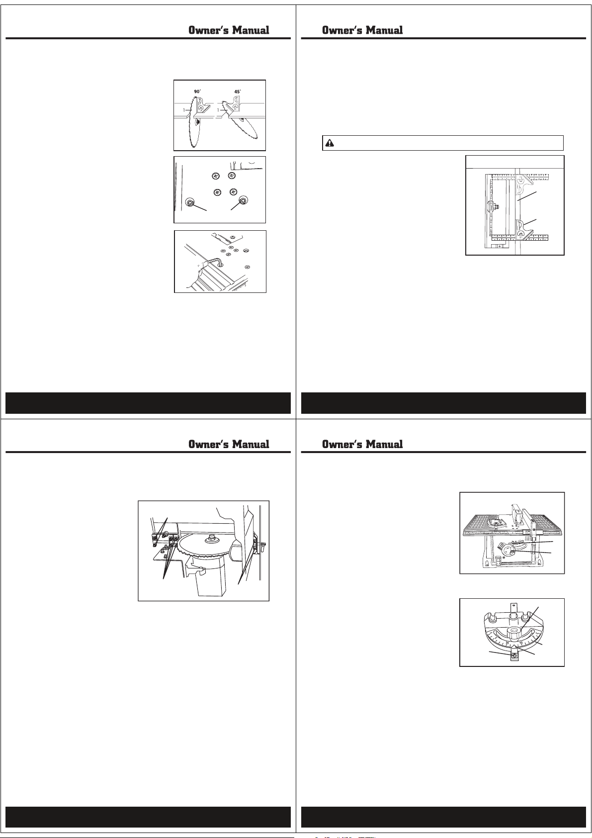
1.When the blade is positioned at 90°, adjust the blade tilt pointer to read 0°on the scale.
2.Loosen the holding screw, position the pointer over 0° and tighten the screw.
Note: Always make a trial cut on scrap wood when making critical cuts. Measure for cut precision.
Blade parallel to the miter gauge groove (Fig. 18)
1.Remove the safety key and unplug the saw.
2.Move the blade guard out of the way.
3.Raise the blade to the highest position and set it
to the 0° angle (90° straight up).
4.Select a tooth with a “right set” on the end of the
blade closest to you. Mark it with a marker.
5.Place the combination square base (1) against
the left side of the right miter gauge groove (2).
6.Adjust the rule so it touches the front marked
tooth. Lock the ruler so it holds its position in the
square assembly.
7.Rotate the blade bringing the marked tooth to the
rear and about 1/2” (13 mm) above the table.
8.Slide the combination square carefully to the rear
until the ruler touches the marked tooth.
9.If the ruler touches the marked tooth at the front
and rear positions, no adjustment is needed at this time. If the front and
rear measurements are not the same, the blade is not parallel to the miter
slot and must be adjusted. See page 18, “Adjusting the blade so it is
parallel to the miter gauge groove.”
1
2
Fig. 18
WARNING: This adjustment must be correct or kickback could result, and accurate cuts will
not be made.
Assembly and adjustments (continued)
17
Adjusting the 90°and 45°positive stops (Fig. 15–17)
The saw has positive stops that will quickly position the saw
blade at 90°or 45° to the table. Make adjustments only if
necessary.
Note: 90° and 45° blade adjustment screws require a 5mm
Allen wrench (supplied) and 10mm wrench or socket
(not supplied) for adjustment. To access the 10mm
nut attached to the 90°and 45°blade adjustment
screws, turn the saw on its left side. Makesure the
saw is secure.
Adjust the 90°Stop
1.Disconnect the saw from the power source.
2.Turn the blade elevation/tilting control wheel and
raise the blade to the maximum elevation.
3.Loosen the blade lock knob. Push in the blade
elevation/tilting control wheel and rotate
counterclockwise as far as possible.
4.Place a combination square on the table and
against the blade (1) to determine if the blade is at
a 90°angle to the table.
5.If the blade is not at a 90° angle to the table, turn
the 90° adjusting socket head screw (2) left to reduce
the angle or right to increase the angle.
Adjust the 45°Stop
1.Disconnect the saw from the power source.
2.Turn the blade elevation/tilting control wheel and
raise the blade to the maximum elevation.
3.Loosen the blade lock knob. Push in the blade
elevation/tilting control wheel and rotate clockwise as far as possible.
4.Place a combination square on the table and against the blade (1) to
determine if the blade is at a 45°angle to the table.
5.If the blade is not at a 45° angle to the table, turn the 45° adjusting socket
head screw (3) left to reduce the angle or right to increase the angle.
Fig. 15
Fig. 16
Fig. 17
23
16
Assembly and adjustments (continued)
Adjusting the blade so it is parallel to the miter gauge groove (Fig. 19)
1.Remove the combination square
(used on page 17) and stand the saw
on its left side so that you can access
the eight adjustment nuts (1,2, 3)
that secure the axis rodto the table.
Make sure the tableis secure.
Note: Place folded pieces of
cardboard over the blade to
protect your hands.
2.Use a 10 mm wrench to loosen all
eight adjustment nuts about a half
turn each.
3.Place the saw in the upright position.
4.Move the blade carefully to the left or
right until it is aligned.
5.Check the alignment with the
combination square (see steps 4–8 on page 17).
6.Tighten the two front (1) and two rear (2) adjustment nuts. Reach under
the front and rearof the table with a wrench to access these nuts.
7.Re-check the alignment. If additional adjustment is needed, loosen only
the two front adjustment nuts (1) and repeat steps 4 and 5 until the blade
is parallel to the miter slot.
8.Tighten the two front adjustment nuts (1)
9.Stand the saw on its left side and tighten the four center adjustment
nuts (3).
10.Place the saw upright on the table and re-check the alignment to make
sure the blade isparallel to the miter slot.
Fig. 19
3
1
2
Assembly and adjustments (continued)
Raising the blade (Fig. 20)
To raise or lower the blade, turn the blade
elevation/tilting control wheel (1) to the desired
bladeheight.
Tilting the blade (Fig. 20)
To tilt the saw blade for bevel cutting, loosen the
blade bevel lock knob (2) and push in the blade
elevation/tilting control wheel (1) . Turn the wheel
counterclockwise to increase the angle; turn the
wheel clockwise to lower the angle. Tighten the
blade bevel lock knob (2) to secure.
Miter gauge adjustment (Fig. 21)
1.Make sure that the miter gauge will slide freely.
2.Loosen the lock knob (1). Set the pointer (2) to the
90° mark on the scale.
3.Make a 90° cut in a piece of scrap wood. Check cut
piece to see if it was cut at 90°. If it is not, continue
to adjust the miter gauge body (3) until the wood
piece is cut at 90°.
4.When a 90°cut has been made, loosen the
pointerscrew (4) and set on the 90°scale mark.
Tighten screw.
Fig. 20
Fig. 21
2
1
1
4
3
2
18
19
Page 6
Operation
Operation(continued)
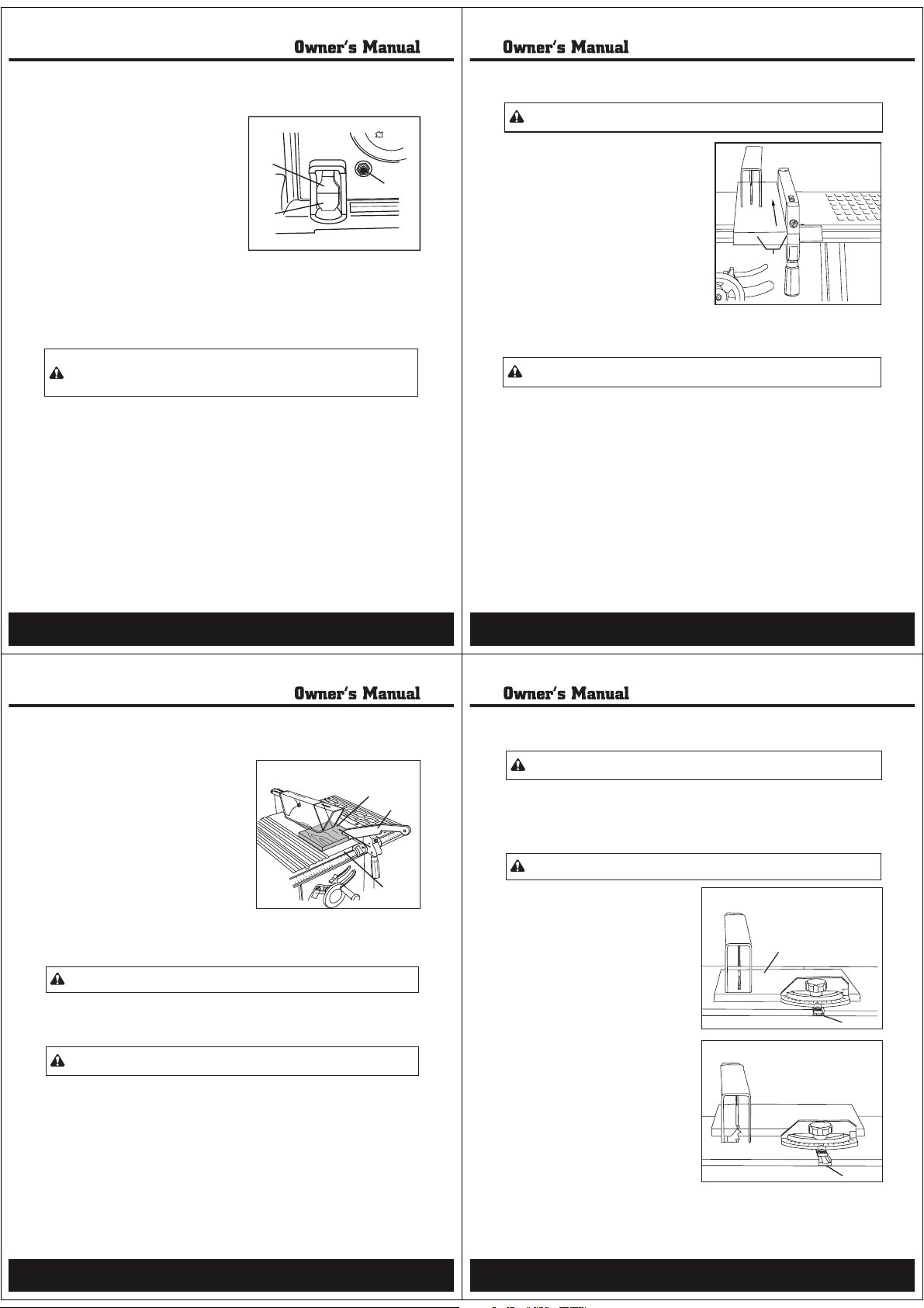
Cutting Operations (Fig. 23)
There are two basic types of cuts: ripping and cross
cutting. Ripping is cutting along the length and the
grain of the workpiece. Cross-cutting is cutting across
the grain of the workpiece. Neither ripping nor crosscutting is safe to do freehand. Ripping requires the
use of a rip fence, and cross-cutting requires a miter
gauge.
CAUTION! Each time, before you use the saw,
makesure:
• Blade is tight on the arbor.
• Blade bevel lock knob is tight.
• If ripping, fence knob is tight and fence is parallel
to the miter gauge grooves.
• Blade guard is in place and working properly.
• Saw operator is wearing safety glasses.
Failure to adhere to these safety rules, and those printed in the front of this
manual, can greatly increase the likelihood of injury.
Ripping (Fig. 24)
1.Remove the miter gauge. Secure the rip fence to the table.
2.Raise the blade so it is about 1/8" (3 mm) higher than the top of the workpiece (1).
3.Place the workpiece flat on the table and against the fence. Keep the workpiece about
1"(25mm) away from the blade.
CAUTION! The workpiece must lay straight against the fence. It must not be warped, twisted,
or bowed.
4.Turn the saw ON and wait for the blade to reach full speed.
5.Feed the workpiece slowly into the blade by pushing forward only on the section of
workpiece (1)that will pass between the blade and the fence.
1
Fig. 23
WARNING: To prevent careless mistakes, always pay close attention when using the table
saw. A careless fraction of a second is enough to cause severe injury.
WARNING: To avoid kickback, push forward on the section of the workpiece that will pass
between the blade and the fence.
21
ON/OFF switch (Fig. 22)
The ON/OFF switch has a removable safety key to
protect against unauthorized use.
1.To turn the saw ON, insert the safety key (1) into
the switch (2), if needed. Move the switch
upward to the ON position.
2.To turn the saw OFF, move the switch downward
to the OFF position.
3.To lock the switch in the OFF position, grasp the
safety key (1) , and pull it out of the switch. With
the safety key removed, the switch will not
operate.
Note: If the safety key is removed while the saw
is running, the saw can be turned OFF but
cannot be restarted without inserting the
safety key (1).
Overload protection (Fig. 22)
To prevent an accidental startup if the overload reset switch is pushed, the on/off
WARNING:
switch should be in the OFF position, and the plug should be removed from the power source
while cool-down takes place. Overheating may be caused by misaligned parts or a dull blade.
Inspect your saw for proper setup before using it again.
This saw has an overload reset switch (3) that will restart the motor after it shuts off due to
overloading or low voltage. If the motor stops during operation:
1.Turn the ON/OFF switch (2) to the OFF position.
2.Wait about five minutes for the motor to cool.
3.Push in on the overload reset switch (3).
4.Turn the switch to the ON position.
Fig. 22
1
2
3
20
Operation(continued)
6.Keep your thumbs off the table top. When both of
your thumbs touch the front edge of the table (2),
finish the cut with a push stick (3).
7.The push stick (3) should always be used when
the ripped workpiece (1) is less than 6" (152 mm)
wide.
8. Continue pushing the workpiece with the push
stick (3) until it passes the blade guard and clears
the rear of the table.
9.Do not pull the workpiece back when the blade is
turning. Turn the switch OFF. When the blade
stops completely, slide the workpiece out.
Note: If the blade is jammed, raise the anti-
kickback pawls on each side of the splitter
and slide the workpiece out.
Bevel ripping
WARNING:
This cut is the same as ripping, but the bevel angle of the blade is set to an angle other than 0°.
Ripping small pieces
1.It is NOT SAFE to rip small pieces. Instead, rip a larger piece to obtain the size of the
desired piece.
2.When you need to rip, a small width and your hand cannot safely be put between the blade
and the rip fence, use one or more push sticks to move the workpiece.
Cut only with the workpiece and the fence on the right side of the blade.
WARNING: Avoid injury from blade contact.Do not make through-saw cuts narrower than
1/2" (13 mm) wide.
Fig. 24
1
Operation(continued)
WARNING: To prevent careless mistakes, always pay close attention when using your table
saw. a careless fraction of a second is enough to case severe injury.
Cross-cutting (Fig. 25)
3
2
1.Remove the rip fence and place the miter gauge in the right side groove
2.Adjust the blade height so it is 1/8" (3 mm) higher than the top of the workpiece (2).
3.Hold the workpiece firmly against the miter gauge with the blade path in line with the
desired cut location. Move the workpiece to a distance of 1" (25 mm) from the blade.
WARNING:
Keep both hands away from the blade and the path of the blade.
4.Start the saw and wait for the blade to reach
full speed.
5.Keep the workpiece against the face of the
miter gauge and flat against the table. Slowly
push the workpiece through the blade.
6.Do not pull the workpiece back with the blade
turning. Turn the switch OFF, and carefully
slide the workpiece out when the blade is
completely stopped.
Bevel cross-cutting (Fig. 26)
This cutting operation is the same as cross-
cutting except the blade is at a bevel angle
other than 0°.
1.Adjust the blade to the desired angle, and
tighten the blade bevel lock knob.
2.Always work to the right side of the blade.
The miter gauge must be in the right side
groove (1). The miter gauge must be used in
the right side groove or it will interfere with
the blade guard.
(1) .
Fig. 25
2
1
Fig. 26
1
22
23
Page 7
Operation(continued)
Operation(continued)
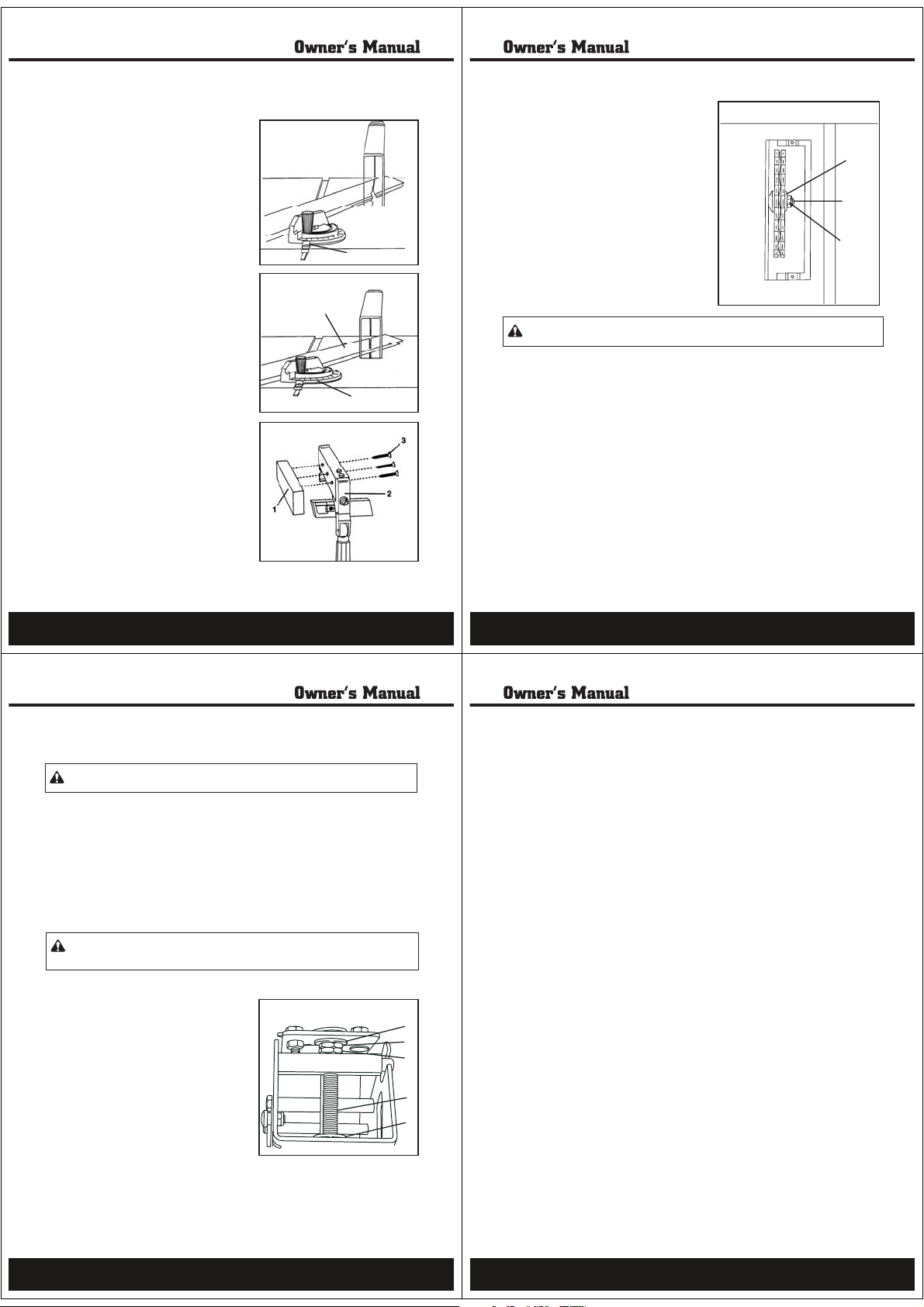
Dado cuts (Fig. 30)
1.A dado table insert is included with this saw.
Remove the saw blade and blade guard. Install a
dado blade and dado table insert.
2.Instructions for operating the dado are packed with
the separately purchased dado set.
3.The arbor (1) on this saw restricts the maximum
width of the cut to 1/2" (13 mm).
4.It is not necessary to install the outside flange (2)
before installing the arbor nut (3). Make sure that
the arbor nut (3) is tight, and that at least one
thread of the arbor sticks out past the nut.
5.You must remove the blade guard and splitter
when using the dado. Exercise caution while the
dado is operating.
6.Check the saw to make sure the dado will not
strike the housing, insert, or motor while in
operation.
1
2
3
Fig. 30
WARNING: For your own safety, always replace the blade, blade guard assembly, and blade
insert when you are finished with the dado operation.
25
Compound miter cross-cutting (Fig. 27)
This sawing operation combines a miter angle with a
bevel angle.
1.Set the miter gauge to the desired angle (1).
2.Set the blade bevel to the desired angle.
3.Carefully push the miter gauge to begin the cutting
operation.
Miter cuts (Fig. 28)
This sawing operation is the same as cross-cutting, but
the miter gauge is locked at an angle other than 90°.
1.Hold the workpiece (1) firmly against the miter
gauge (2).
2.Feed the workpiece slowly into the blade to prevent the
workpiece from moving.
Using wood facing on the rip fence (Fig. 29)
When performing some special cutting operations, add
a wood facing (1) to either side of the rip fence (2):
1.Use a smooth, straight 3/4” (19 mm) thick wood
board (1) that is as long as the rip fence.
2.Attach the wood facing to the fence with wood
screws (3) through holes drilled through the fence.
Note: The holes in the fence are not pre-drilled.
A wood fence should be used when ripping
material such as thin paneling to prevent the
material from catching between the bottom of
the fence and the table.
Fig. 27
1
Fig. 28
1
2
Fig. 29
24
Maintenance
WARNING: For your own safety, turn the switch off and remove the safety key. Unplug the
power cord from the outlet before maintaining or lubricating the saw.
General
1.Clean out all sawdust that has accumulated inside the saw cabinet and the motor.
2.Polish the saw table with an automotive wax to keep it clean and to make it easier to move
the workpiece.
3.Clean blades with pitch and gum remover.
4.Aworn, cut, or damaged power cord should be replaced immediately.
5.Use liquid dish washing detergent and water to clean all plastic parts.
Note: Certain cleaning chemicals can damage plastic parts.
6.Do not use the following cleaning chemicals or solvents: gasoline, carbon tetrachloride,
chlorinated solvents, ammonia, or any household detergents containing ammonia.
WARNING: All electrical and mechanical repairs should be attempted only by a qualified
service technician. Use only identical replacement parts. Any other parts may create
a hazard.
Blade elevation and tilting mechanism (Fig. 31)
After every five hours of operation, the blade elevation
and tilting mechanism should be checked for
looseness, binding, or other abnormalities. Disconnect
the saw from the power source, turn the saw upside
down and pull up and down on the motor unit. Observe
any movement in the motor mounting mechanism.
Looseness or play in the blade raising screw (1) should
be adjusted as follows:
1.Loosen the nut (2).
2.Adjust the nut (3) until it is finger-tight against the
bracket(4), then back off the nut (3) 1/6 turn.
3.Tighten nut (2) . The maximum allowable play of
the screw rod (1) is 5/32" (4 mm). Place a small
amount of dry lubricant (such as graphite or silicon)
on the screw rod (1) at the thrust washer (5) . Do
not oil the threads of screw rod (1) . The screw
rod (1) must be kept clean and free of saw dust,
gum, pitch, and other contaminants for smooth
operation.
Fig. 31
Maintenance(continued)
Note: If excessive looseness is observed in any other part of the blade elevation mechanism or
tilting mechanism, take the complete unit to an authorized service center.
Lubrication
All motor bearings are permanently lubricated at the factory and require no additional lubrication.
4
3
2
1
5
Lubricate all mechanical parts where a pivot or threaded rod is present, lubricate with graphite or
silicone. These dry lubricants will not hold sawdust.
26
27
Page 8
Troubleshooting
Replacement parts
When servicing your STEELE® 10" Bench Saw, use identical STEELE® replacement parts only.
Use of any other parts may cause product damage. Any and all servicing of the
bench saw should be performed by a qualified service technician.
WARNING:
ANY ATTEMPT TO REPAIR OR REPLACE ELECTRICAL PARTS ON THIS TOOL
MAY CREATE AHAZARD UNLESS REPAIR IS DONE BY QUALIFIED SERVICE TECHNICIANS.
29
WARNING:
For your safety, turn the switch OFF and remove the safety key. Unplug the
power cord from the outlet before maintaining or lubricating the saw.
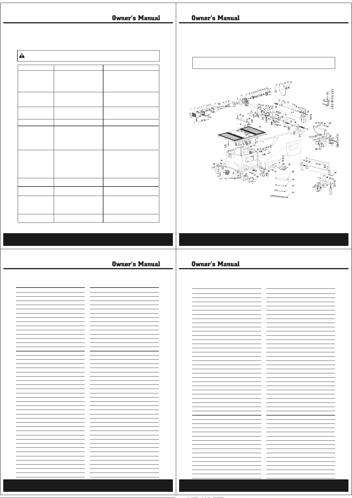
PROBLEM
Saw will not start.
Does not make accurate 45°
and 90° rip cuts.
Material pinches blade when
ripping.
Material binds on splitter.
Saw makes unsatisfactory
cuts.
Material kicked back from
blade.
Blade does not raise or tilt
freely.
Blade does not reach full
speed.
Machine vibrates excessively.
Does not make 45°and 90°
cross cuts.
PROBABLE CAUSE
1. Saw not plugged in.
2. Fuse blown or circuit breaker tripped.
3. Cord damaged.
4. Overload or low voltage.
1. Positive stop not adjusted correctly.
2. Tilt angle pointer not set correctly.
1. Rip fence not aligned with blade.
2. Warped wood, edge against fence is
not straight.
Splitter not aligned correctly with blade.
1. Dull blade.
2. Blade mounted backwards.
3. Gum or pitch on blade.
4. Incorrect blade for work.
5. Gum or pitch on table causing erratic
feed.
1. Rip fence out of alignment.
2. Splitter not aligned with blade.
3. Feeding stock without rip fence.
4. Splitter not in place.
5. Dull blade.
6. The operator letting go of material
before it is past the saw blade.
7. Miter angle lock knob is not tight.
Sawdust and dirt in elevation and tilting
mechanisms.
1. Extension cord too tight or too long.
2. Low house voltage.
1. Saw not mounted securely to stand or
workbench.
2. Stand or bench on uneven floor.
3. Damaged saw blade.
Miter gauge out of adjustment.
REMEDY
1. Plug in the saw.
2. Replace fuse or reset circuit breaker.
3. Have cord replaced by an authorized service
center.
4. Turn the saw switch to OFF, wait 5 minutes,
push the reset switch, and turn the saw ON.
1. Check blade with square and adjust positive
stop.
2. Check blade with square and adjust pointer
to zero.
1. Check and adjust rip fence.
2. Select another piece of wood.
Check and align splitter with blade.
1. Replace blade.
2. Turn blade around.
3. Remove blade and clean with turpentine and
coarse steel wool.
4. Change the blade.
5. Clean table with turpentine and steel wool.
1. Align rip fence with miter gauge.
2. Align splitter with blade.
3. Install and use rip fence.
4. Install and use splitter (with guard).
5. Replace blade.
6. Push material all the way past blade before
releasing work.
7. Tighten knob.
Brush or blow out loose dust and dirt.
1. Replace with adequate size cord.
2. Contact your electric company.
1. Tighten all mounting hardware.
2. Reposition on flat level surface. Fasten to
floor if necessary.
3. Replace blade.
Adjust miter gauge.
28
Replacement parts ... continued
APA Parts No. No. Description QTY APA Parts No. No. Description QTY
PB101-01-SD
PB101-02-SD
PB101-03-SD
PB101-04-SD
PB101-05-SD
PB101-06-SD
PB101-07-SD
PB101-08-SD
PB101-09-SD
PB101-10-SD
PB101-11-SD
PB101-12-SD
PB101-13-SD
PB101-14-SD
PB101-15-SD
PB101-16-SD
PB101-17-SD
PB101-18-SD
PB101-19-SD
PB101-20-SD
PB101-21-SD
PB101-22-SD
PB101-23-SD
PB101-24-SD
PB101-25-SD
PB101-26-SD
PB101-27-SD
PB101-28-SD
PB101-29-SD
PB101-30-SD
PB101-31-SD
PB101-32-SD
PB101-33-SD
PB101-34-SD
PB101-35-SD
PB101-36-SD
PB101-37-SD
PB101-38-SD
PB101-39-SD
PB101-40-SD
PB101-41-SD
PB101-42-SD
PB101-43-SD
PB101-44-SD
PB101-45-SD
GB6562-86 STx16)
01
Rear cover
02
Strain relief
03
Brush holder
04
Carbon brush
05
Wire connector
06
Motor housing
07
Screw(GB818-85 M5x30)
08
Spring washer(GB93-87 5)
09
10
11
12
13
14
15
16
17
18
19
20
21
22
23
24
25
26
27
28
29
30
31
32
33
34
35
36
37
38
39
40
41
42
43
44
45
GB95-85 5)
Flat washer (
Stator
GB818-85 M5x78)
Screw (
GBøT276-94 629z)
Bearing(
Rotor
GBøT276-94 6201)
Bearing(
Wind washer
Gear box
GB894.1-86 14)
C-ring(
GBøT276-94 607z)
Bearing(
Gear
Spindle
GB61095-79 A5x12)
Key (
GB894.3-86 35)
C-ring (
GBøT276-94 6003)
Bearing(
Bushing
Gear box cover
In flange
Blade
Out flange
Blade nut
Pin
Screw (GB5781-86 M6x85)
Pin
Link plate
Lock nut(GBøT889.1-2000 M6)
Adjustment support
Nut
Adjustment pin
Bolt (GB5781-86 M8x18)
Support board A
Scale board
Screw (GB818-85 M5x10)
Nut (GBøT889.1-2000 M8)
Indicator
Block plate
PB101-46-SD
3Screw (
1
PB101-47-SD
1
PB101-48-SD
2
PB101-49-SD
2
PB101-50-SD
1
PB101-51-SD
1
PB101-52-SD
6
PB101-53-SD
11
PB101-54-SD
8
PB101-55-SD
1
PB101-56-SD
2
PB101-57-SD
1
PB101-58-SD
1
PB101-59-SD
1
PB101-60-SD
1
PB101-61-SD
1
PB101-62-SD
1
PB101-63-SD
1
PB101-64-SD
1
PB101-65-SD
1
PB101-66-SD
1
PB101-68-SD
1
PB101-68-SD
1
PB101-69-SD
1
PB101-70-SD
1
PB101-71-SD
1
PB101-72-SD
1
PB101-73-SD
1
PB101-74-SD
1
PB101-75-SD
1
PB101-76-SD
1
PB101-77-SD
1
PB101-78-SD
1
PB101-79-SD
14
PB101-80-SD
1
PB101-81-SD
2
PB101-82-SD
1
PB101-83-SD
2
PB101-84-SD
1
PB101-85-SD
1
PB101-86-SD
2
PB101-87-SD
2
PB101-88-SD
1
PB101-89-SD
1
PB101-90-SD
Finger board
46
Wave washer(GB955-87 10)
47
Spring
48
Adjustment bolt
49
GB879-86 2.5x22)
Pin (
50
Control wheel
51
Nut (
GB6170-86 M8)
52
Wheel label
53
Wheel handle
54
Screw
55
56
57
58
59
60
61
62
63
64
65
66
67
68
69
70
71
72
73
74
75
76
77
78
79
80
81
82
83
84
85
86
87
88
89
90
Gear washer(
GB95-85 4)
Flat washer(
GB818-85 M4x10)
Screw(
Lock washer(
GB5781-86 M6x16)
Bolt (
Shaft bube
Screw
GB6170-86 M6)
Big nut (
Washer plate
Lock knob
Screw
Spring washer(
Support board B
GB95-85 6)
Flat washer(
GB879-86 4x8)
Spring pin(
Nut
Spring
Flat washer (
GB6170-86 M5)
Nut (
Pivot rod
Underlay
GB70-85 M5x22)
Screw(
Rear axis
Plate
GB819-85 M6x25)
Screw(
GB70-85 M5x12)
Screw(
Table insert
GB862.2-87 5)
Washer (
Screw
GB70-85 M6x25)
Screw(
Work table
GB5781-86 M6x25)
Bolt (
Gear washer(
GB70-85 M5x8)
Hex screw(
Press plate
GB8622-87 4)
GB62.2-87 6)
GB848-85 10)
GB862.2-87 5)
GB93-87 6)
Replacement parts
1
5
1
1
1
1
2
1
1
1
1
4
1
12
3
3
1
4
1
1
4
16
1
5
3
3
1
1
1
1
1
1
1
1
1
2
1
1
1
2
1
1
1
1
6
APA Parts No. No. Description QTY APA Parts No. No. Description QTY
PB101-91-SD
PB101-92-SD
PB101-93-SD
PB101-94-SD
PB101-95-SD
PB101-96-SD
PB101-97-SD
PB101-98-SD
PB101-99-SD
PB101-100-SD
PB101-101-SD
PB101-102-SD
PB101-103-SD
PB101-104-SD
PB101-105-SD
PB101-106-SD
PB101-107-SD
PB101-108-SD
PB101-109-SD
PB101-110-SD
PB101-111-SD
PB101-112-SD
PB101-113-SD
PB101-114-SD
PB101-115-SD
PB101-116-SD
PB101-117-SD
PB101-118-SD
PB101-119-SD
PB101-120-SD
PB101-121-SD
PB101-122-SD
PB101-123-SD
PB101-124-SD
PB101-125-SD
PB101-126-SD
PB101-127-SD
PB101-128-SD
PB101-129-SD
PB101-130-SD
91
GB827-86 2x6)
92
Rivet (
Screw(
GB848-85 ST4x12)
93
Spring plate
94
Fence base
95
Base
96
Data label
97
Inner plate
98
GB819-85 M4x8)
Screw(
99
Gear plate
100
GB848-85 ST4x16)
Screw(
101
Switch base
102
Switch
103
Circuit breaker
104
Breaker nut
105
Switch box
106
Dustproof ring
107
Wire holder
108
Screw (
109
Strain relief
110
Spindle
111
Dust port cover
112
Screw (
113
GB6170-86 M4)
Nut (
114
Mitre gauge storage
115
Spring plate
116
Spring washer(
117
Screw (
118
Rubber foot
119
Rear plate
120
Spring
121
Spring defence board
122
Fence
123
Bolt
124
Hex bolt(
125
Washer plate
126
Fence support
127
Long nut
128
Spring pin (
129
Bias wheel
130
GB848-85 ST4x16)
GB848-85 ST4x16)
GB93-87 4)
GB818-85 M4x10)
GB5871-86 M6x10)
GB878-86 3x22)
1Scale label
3
11
2
2
1
1
1
9
1
8
2
12
3
3
1
1
1
2
1
1
1
2
1
1
1
2
1
4
1
1
1
1
1
2
1
1
2
1
2
PB101-131-SD
PB101-132-SD
PB101-133-SD
PB101-134-SD
PB101-135-SD
PB101-136-SD
PB101-137-SD
PB101-138-SD
PB101-139-SD
PB101-140-SD
PB101-141-SD
PB101-142-SD
PB101-143-SD
PB101-144-SD
PB101-145-SD
PB101-146-SD
PB101-147-SD
PB101-148-SD
PB101-149-SD
PB101-150-SD
PB101-151-SD
PB101-152-SD
PB101-153-SD
PB101-154-SD
PB101-155-SD
PB101-156-SD
PB101-157-SD
PB101-158-SD
PB101-159-SD
PB101-160-SD
PB101-161-SD
PB101-162-SD
PB101-163-SD
PB101-164-SD
PB101-165-SD
PB101-166-SD
PB101-167-SD
PB101-168-SD
PB101-169-SD
Pin
131
Fence handle
132
Pin
133
Front nip board
134
Screw (
135
Indicator
136
Pin
137
Guide ruler
138
Gauge pointer
139
Spring washer
140
Screw (
141
Mitre gauge
142
Angle bolt
143
Lock knob
144
Knob cover
145
Blade guard
146
Block pin
147
Spring washer
148
Guard arm
149
Bush
150
Spring
151
Follow blade board
152
Anti-kickback pawl
153
Bolt (
154
Bolt (
155
Flat washer(
156
Block bushing-R
157
Spring pin(
158
Block bushing-L
159
Hex bolt(
160
Press plate
161
Hex bolt(
162
Flat washer (
163
Support base
164
Dado inser
165
Wrench
166
Open ended wrench
167
Push stick
168
Power cord
169
GB818-86 M4x6)
GB818-86 M4X6)
GB5781-86 M6x22)
GB5781-86 M6x40)
GB95-85 6)
GB879-86 3x10)
GB70-85 M6x12)
GB70-85 M5x20)
B95-86-5)
1
1
1
1
1
1
1
1
1
1
1
1
1
1
1
1
2
2
1
2
2
1
2
1
2
6
1
1
1
6
1
1
1
1
1
1
1
4
1
30
31
Page 9
Steele® warrants to the original purchaser who uses the product in a consumer application (personal,
Merchandise sold by Steele® which has been manufactured by and identified as the product of another
company, such as gasoline engines. The product manufacturer’s warranty, if any, will apply.
ANY INCIDENTAL, INDIRECT OR CONSEQUENTIAL LOSS, DAMAGE, OR EXPENSE THAT MAY RESULT
FROM ANY DEFECTS, FAILURE OR MALFUNCTION OF THE PRODUCT IS NOT COVERED BY THIS
WARRANTY. Some states do not allow the exclusion, so it may not apply to you.
IMPLIED WARRANTIES, INCLUDING THOSE OF MERCHANTABILITY OR FITNESS FOR A PARTICULAR
PURPOSE, ARE LIMITED TO ONE YEAR FROM THE DATE OF ORIGINAL PURCHASE. Some states do not
allow limitations on how long an implied warranty lasts, so the above limitations may not apply to you.
33
residential or household usage) that all products covered under this warranty are free from defects in
material and workmanship for one year from the date of purchase. All products covered by this limited
warranty which are used in commercial applications (i.e. income producing) are warranted to be free of
defects in material and workmanship for 90 days from the date of original purchase. Products covered
under this warranty include air compressors, tools, service parts, pressure washers and generators.
Steele® will repair or replace, at Steele®’s sole option, products or components which have failed within
the warranty period. Service will be scheduled according to the normal work flow and business hours at
the service center location, and the availability of replacement parts. All decisions of Steele® with regard
to this limited warranty shall be final.
This warranty gives you specific legal rights, and you may also have other rights which vary from state to
state.
RESPONSIBILITY OF ORIGINAL PURCHASER (initial User):
To process a warranty claim on this product, DO NOT return item to the retailer. The product must be
evaluated by an Authorized Warranty Service Center. For the location of the nearest Authorized Warranty
Service Center contact the retailer or place of purchase.
Retain original cash register sales receipt as proof of purchase for warranty to work.
Use reasonable care in the operation and maintenance of the
Manual(s).
Deliver or ship the product to the Authorized Warranty Service Center. Freight costs, if any must be paid
by the purchaser. If the purchaser does not receive satisfactory results form the Authorized Warranty
Service Center, the purchaser should contact Steele® toll free 888-896-6881.
THIS WARRANTY DOES NOT COVER:
Merchandise sold as reconditioned, used as rental equipment, or floor or display models.
Merchandise that has become damaged or inoperative because of ordinary wear, misuse, cold, heat, rain,
excessive humidity, freeze damage, use of improper chemicals, negligence, accident, failure to operate the
product in accordance with the instructions provided in the Owner’s Manual(s) supplied with
improper maintenance, the use of accessories or attachments not recommended by Steele®, or
unauthorized repair or alterations.
Repair and transportation costs of merchandise determine not to be defective.
Costs associated with assembly, required oil, adjustments or other installation and start-up costs.
Expendable parts or accessories supplied with the product which are expected to become inoperative or
unusable after a reasonable period of use.
product as described in the Owner’s
the product,
32
Push stick pattern
CAUTION!
or plywood
strong wood
Use only good
Optional
PUSH STICK
material to be cut
less than width of
wood or thickness
Make from 1/2" or 3/4"
prevent hand
Notch to help
hanging hole
from slipping
Cut off here to
Cut off here to
push 1/4" wood
34
push 1/2" wood
1/2" Squares
 Loading...