

Page 1
WARNING! Read and understand all the instructions before attempting to as-
semble or operate the tool. Failure to follow the instructions listed below could
result in electric shock, fire and/or serious personal injury.
SAVETHESE INSTRUCTIONS.
Refer to them often and use them to instruct others.
WORK AREA
1. KEEPYOUR WORK AREA CLEAN AND WELL LIT. Cluttered benches and dark
areas invite accidents. DO NOT leave tools or pieces of wood on the saw while it
is in operation.
2. DO NOT OPERATE POWERTOOLS IN EXPLOSIVE ENVIRONMENTS, SUCH
AS IN THE PRESENCE OF FLAMMABLE LIQUIDS, GASES OR DUST. Power
tools create sparks, which could ignite dust or fumes.
3. KEEP BYSTANDERS, CHILDREN AND VISITORS AWAYWHILE OPERATING
A POWERTOOL. Distractions could cause you to lose control.
4. STORE IDLETOOLS OUT OF THE REACH OF CHILDREN AND OTHER UNTRAINED PERSONS. Tools are dangerous in the hands of untrained users.
5. NEVER LEAVETHE TOOL RUNNING UNATTENDED.TURN THE POWER OFF.
Don’t leave the tool until it comes to a complete stop.
6. MAKE THE WORKSHOP CHILDPROOF – with padlocks, master switches, or by
removing starter keys.
ELECTRICAL SAFETY
1. BEFORE PLUGGING IN THE TOOL, BE CERTAIN THE OUTLETVOLTAGE
SUPPLIED IS COMPATIBLE WITHTHE VOLTAGE MARKED ON THE NAMEPLATEWITHIN 10%. An outlet voltage incompatible with that specified on the
nameplate can result in serious hazards and damage to the tool.
2. GROUNDINGTOOLS ARE EQUIPPED WITH THREE-PRONG PLUG (THE
GROUNDING BLADE IS THE LONGEST OFTHE 3 BLADES). This plug will fit
into a three-hole electrical receptacle. Do not modify the plug provided. If the plug
does not fit the outlet, have the proper outlet installed by a qualified electrician.
Check with a qualified electrician or service personnel if the grounding instructions are not completely understood, or if in doubt as to whether the tool is
properly grounded.
3. AVOID BODY CONTACT WITH GROUNDED SURFACES SUCH AS PIPES,
RADIATORS, RANGES AND REFRIGERATORS. There is an increased risk of
electric shock if your body is grounded.
4. DO NOT EXPOSE POWERTOOLS TO RAIN ORWET CONDITIONS. Water
entering a power tool will increase the risk of electric shock.
5. DO NOT ABUSETHE CORD. Never use the cord to carry the tool or pull the plug
from an outlet. Keep the cord away from heat, oil, sharp edges or moving parts.
Replace damaged cords immediately. Damaged cords increase the risk of electric
shock.
6. WHEN OPERATING A POWERTOOL OUTSIDE, USE AN OUTDOOR EXTENSION CORD MARKED “W-A” OR “W”. These cords are rated for outdoor use
and reduce the risk of electric shock.
2
PERSO
NAL SAFETY
1
a
o
-
o
2
-
g
d
n
.
3
G.
Make sure the switch is “OFF” before plugging
O
.
4
OOL.
r
5
r
f
.
6. DO NOT STAND ON TOOL OR ITS STAND.
f
o
h
.
Dust masks,
-
s
N
.
TOOL US
1
-
PO
h
2
Use the correct tool for your application.The correct
use the tool for purpose for which it was not intended.
3
.
4
SCO
SOURC
G
S
.
5. KEEP CUTTING TOOLS SHARP AND CLEAN.
g
g
r
SPEC
d i
f
C
OO
a
.
8
mi
.
9
SSO
C
c
1
AND GREASE.
g
g
plastic housing.
1
c
g
blade.
1
GOOD CO
g
a
f
p
-
edf
r
g
d.
13
D
b
y
r
p
.
1
S.
D
use blades with inc
les
Never use bladewashers
defec
b
.
5
.
1
6
cutting.
OUC
18
W
.
19
S.
Mak
c
.
. STAY ALERT.Watch what you are doing and use common sense when operating
power tool. Do not use a tool while tired or under the influence of drugs, alcohol
r medication. A lack of attention while operating power tools could result in seri
us personal injury.
. DRESS PROPERLY.Do not wear loose clothing or jewelry.Keep your hair, cloth
ing and gloves away from moving parts. Loose clothes, jewelry, or long hair could
et caught in moving parts. Roll long sleeves above the elbow. Rubber gloves an
on-skidfootwear are recommended when working outdoors
.AVOID ACCIDENTAL STARTIN
in. Carrying tools with your finger on the switch or plugging in tools that have the
switch “
N” invites accidents
. REMOVE ADJUSTING KEYS OR WRENCHES BEFORE TURNING ON THE
A wrench or a key that is left attached to a rotating part of the tool could
T
esult in personal injury.
. DO NOTOVERREACH.Keep proper footing and balance at all times. Prope
ooting and balance enables better control of the tool in unexpected situations
is tipped or i
7. USE SAFETY EQUIPMENT. ALWAYSWEAR EYE PROTECTION.
. USE CLAMPS OR OTHER PRACTICAL MEASURESTO SECURE AND SUP
. DO NOT FORCE THETOOL.
. DO NOT USETOOL IF THE SWITCH DOES NOT TURN IT ON OR OFF. Any tool
. DI
6. IN
the cutting tool is accidentally contacted. Do not store materials on
r near the tool such that is necessary to stand on the tool or its stand to reac
them
safety shoes, hard hat or hearing protection must be used for appropriate condi
tions. Everyday eyeglasses only have impact resistant lenses, they are NOT
afety glasses.These safety glasses must conform to ANSI Z87.1 requirements.
OTE: Approved glasses have Z87 printed or stamped on them
E ANDCARE
RT THEWORK PIECETO A STABLE PLATFORM. Holding the work piece by
and or against your body is unstable and could lead to a loss of control.
tool will do the job better and safer at the rate for which it was designed. Do not
that cannot be controlled with the switch is dangerous and must be repaired
NNECT THE PLUG FROM THE POWER
ANY ADJUSTMENTS, CHANGING ACCESSORIES OR STORINGTHE TOOL.
uch preventive safety measures reduce the risk of starting the tool accidentally
edges, are less likely to bind and easier to control. When mountin
sharp cuttin
saw blades be certain that the arrow on the blade matches the direction of the ar-
ow marked on the tool and that the teeth are also pointing in the same direction.
T THE GUARDS BEFORE USING ATOOL. KEEP GUARDS IN PLACE
an
n working order. Never operate the tool with any guard or cover removed.
Make sure all guards are operating properly be
3
Serious injury may occur if the tool
E BEFORE MAKIN
Properly maintained tools, with
ore each use.
7. CHECK MOVINGPAR TS FOR BINDING OR ANY OTHER CONDITION THAT
. DO NOT ALTER OR MISUSE THETOOL. Any alteration or modification is a
THE USE OF ANY OTHER ACCE
0. KEEP THE TOOL AND ITS HANDLE DRY, CLEAN AND FREE FROM OIL
1. INSPECT THETOOL CORDS PERIODICALLY. If your cord is damaged, have
2. MAKE SURE YOUR EXTENSION CORD IS IN
. THE DUST GENERATE
4. USE ONLY CORRECT BLADE
. BEFORE MAKING A CUT, BE SURE ALL ADJUSTMENTS ARE SECURE
.AVOID CUTTING NAILS. Inspect for and remove all nails from lumber before
. NEVER T
. NEVER STAR T A TOOL WHEN ANY ROTATING COMPONENT IS IN CONTACT
. DOUBLE CHECK ALL SETUP
T THE NORMAL OPERATION OR SAFETY FEATURES OF THE
MAY AFFE
T
L. If damaged, have the tool serviced before using the tool. Many accidents
re caused by poorly maintained tools
suse and may result in serious personal injury
REATE A HAZARD. Accessories that may be suitable for one type of tool,
MAY
ould create a risk of injury when used on an inappropriate tool.
asoline, petroleum-based products, or any strong solvents to clean your tool.
Followin
it repaired by a qualified service technician at an authorized service facility. Stay
onstantly aware of the cord location and keep it well away from the rotatin
n extension cord, be sure to use one heavy enough to carry the current your tool
will draw. An undersized cord will cause a drop in line voltage resulting in loss o
ower and overheating. A wire gauge size (A.W.G.) of at least 14 is recommend
auge.The smaller the gauge number, the heavier the cor
to
roper dust removal. Use wood dust collection systems whenever possible
lade capacity of your saw is 10” (254 mm)
ITH THEWORKPIECE
ontact with the saw or workpiece before connecting to a power supply
Always use a clean cloth when cleaning. Never use brakefluids,
this rule will reduce the risk or loss of control and deterioration of the
or an extension cord 25 feet or less in length. If in doubt, use the next heavie
our health. Always operate machinery in well ventilated areas and provide fo
or bolts that are
H THE BLADE or other moving parts during use.
RIES NOT SPECIFIED IN THIS MANUAL
NDITION.When usin
y certainwoods and wood products can be injurious
o not
e sure the blade is tight and not making
orrect size ho
tive or incorrect. The maximum
4
.
Page 2
SAVETHESE INSTRUCTIONS.
Ref
.
1
DO NOT OPERATETHIS MACHINE
u
he i
fi
f y
.
3
4
.
5
OSS
,
H
O
OO
S
Hands”
.
O
y
.
OSSYOU
p-
ith
ight hand i
.
SCO
O
SSO-
.
C
G
S, USE O
O
.
1
If the workpiece is bowed
o
c
o
f
obj
.
1
SC
C.
S
.
1
”
C
The s
aw blade must be fed through the workpiece
r
.
W
ARNING!Read and understand all the instructions before attempting to as-
s
/
13. CUT O
e
.
1
WO
r
1
h
W
-
p
b
1
-
SION O
c
p
1
ANYO
i
.
18
-
PO
“
y
1
K
SO
HAND
r
.
20
-
PIEC
Thi
ill hel
2
,
g
-
.
2
K
DO
r
.
2
DO
CUTO
2
idl
d th
ff
2
:
.
f
.
.
•
.
6
26
.
N
O
.
2
k
a
28. ALWAYS TURNTHE MACHINE “OFF”,
r
S
.
2
M
.
3
SENS
S
.
31
-
ING
h
.
W
-
ING,
S
c
k
th
Ŗ
L
,
Ŗ
Cry
Ŗ
A
.
r
.
S
The saw has a precision-built electric motor. It should be connected to a power
the power supply.
.
G
The no-load speed of this tool is approximately 4500 rpm. This speed is not con-
for lights cannot properly carry a power tool motor.Wire that is heavy enough for
hile i
-
.
tions are not completely understood, or if in doubt as to whether the machine is
d.
emble or operate the tool. Failure to follow the instructions listed below could
result in electric shock, fire and
.
to t
2. OBTAIN ADVICE FROM YOUR SUPERVISOR, instructor, or another quali
person i
. FOLLOW ALL WIRING CODESand recommended electrical connections.
. ALWAYS KEEP THE BLADE GUARD IN PLACE and in working order
. USE CLAMPSTO SUPPORT THEWORKPIECE WHENEVER P
SUPPORTING THEWORKPIECE BY HAND
AND OUTSIDE OF THE“NO HAND” AREA AS MARKED WITH A SYMBOL
N THE BASE. DO NOT USE THIS SAW TO CUT PIECESTHAT ARET
MALL TO BE SECURELY CLAMPED. Your hand, if placed inside the “No
6. DO NOT REACH IN BACK OF THE SAW BLADE BEHINDTHE FENCE WITH
EITHER HAND F
our hand may not be obvious and you may be seriously injured
7. NEVER CR
porting the workpiece “cross handed” i.e. holding the left side of the workpiece
w
8. ALWAYS DI
BEF
RIES.You may unintentionally start the saw, leading to serious personal injury
9. MITER SAWS ARE INTENDEDTO CUT WOOD OR WOODLIKE PRODUCTS,
THEY
FERROUS MATERIAL SUCH AS BARS,RODS, STUDS, ETC. HOWEVER
, IF CUTTING MATERIALS LIKE ALUMINUM OR OTHER NON-FERROUS
METAL
N
sparking and will damage the lower guard and will overload the motor
0. INSPECTYOUR WORKPIECE BEFORE CUTTING.
r warped, clamp it with the outside bowedface toward the fence. Always make
ertain that there is no gap between the workpiece, fence and table along the line
f the cut. Bent or warped workpieces can twist or lock and may cause binding on
the spinning saw blade while cutting. Also, make sure there are no nails or
ects in the workpiece
1. DO NOT USE THE SAW UNTILTHE TABLE IS CLEAR OF ALL TOOLS,WOOD
RAPS, ET
the revolving blade can be thrown with high speed at the operator
2. DO NOT FEED THEWORKPIECE INTOTHE BLADE OR CUT “FREEHAND
IN ANY WAY. THE WORKPIECE MUST BE STATIONARY AND CLAMPED OR
BRA
smoothly and at a ratewhich will not overload the saw’s moto
er to them often and use them to instruct others
nstructions.
ou are not familiar with the operation of this machine
region, can easily slip or be pulled into the blade
your r
RE MAKING ANY ADJUSTMENTS OR ATTACHING ANY ACCE
ANNOT BE USED WITH ABRASIVE CUTOFF WHEELS FOR CUTTIN
N-FERROUS METAL CUTTING.Cuttingferrous materials causes excessive
ED BY YOUR HAND.
or serious personal injury.
ntil it is assembled and installed according
ed
YOU MUST ALWAYS KEEP YOUR
R ANY REASON. The proximity of the spinning saw blade to
R HAND OVER THE INTENDED LINE OF CUTTING.Su
s very dangerous
NNECT THE POWER CORD FROM THE POWER SOURCE
NLY SAW BLADES SPECIFICALLY RECOMMENDED FOR
mall debris or loose pieces of wood or other objects that contact
IBLE. IF
oreign
NLY ONE WORKPIECE AT ATIME.Multiple workpieces cannot be ad-
quately clamped or braced and may bind on the blade or shift during cutting
4. BE CERTAIN THE MITER SAW IS MOUNTED OR PLACED ON A LEVEL, FIRM
RK SURFACE BEFORE USING. A level and firm work surface reduces the
isk of the miter saw becoming unstable.
5. PLANYOUR WORK.Provide adequate support accessories such as tables, saw
orses, table extension, etc.for workpieces wider or longer than the table top.
orkpieces longer or wider than the miter saw table can tip if not securely sup
orted. If the cutoff piece or workpiece tips it can lift the lower guard or be thrown
y the spinning blade.
6. DO NOT USE ANOTHER PERSON AS A SUBSTITUTE FOR A TABLE EXTEN
R AS ADDITIONAL SUPPORT.Unstable supportfor the workpiece can
ause the blade to bind or the workpiece to shift during the cutting operation
ulling you and the helper into the spinning blade.
7. THE CUTOFF PIECE MUST NOT BE JAMMED AGAINST OR PRESSURED BY
THER MEANS AGAINST THE SPINNING SAW BLADE. If confined, i.e.
ng length stops, it could get wedged against the blade and thrown violently
us
. ALWAYS USE A CLAMP OR A FIXTURE DESIGNED TO PROPERLY SUP
RT ROUND MATERIAL SUCH AS DOWEL RODS, OR TUBING.Rods have a
tendency to roll while being cut, causing the blade to
our hand into the blade.
9. WHEN CUTTING IRREGULARLY SHAPED WORKPIECES, PLANYOUR WOR
IT WILL NOT SLIP AND PINCH THE BLADE AND BETORN FROMYOUR
. A piece of molding, for example, must be lie flat or be held by a fixture o
jig that will not let it twist., rock or slip while being cut
. LET THE BLADE REACH FULL SPEED BEFORE CONTACTINGTHE WORK
E.
s w
1. IF THE WORKPIECE OR BLADE BECOMES JAMMED OR BOGGED DOWN
TURN THE MITER SAW “OFF” BY RELEASING SWITCH.Wait for all movin
parts to stop and unplug the miter saw, then work to free the jammed material.
Continued sawing with a jammed workpiece could cause a loss of control or dam
age to the miter saw
2. THE BRAKING ACTION OF THE SAW CAUSESTHE SAW HEADTO JER
WNWARD. Be ready for this reaction when making an incomplete cut or when
eleasing the switch before the head is completely in the down position
3. AFTER FINISHINGTHE CUT, RELEASE THE SWITCH, HOLD THE SAW ARM
WN AND WAIT FOR BLADE TO STOP BEFORE REMOVINGWORK OR
FF PIECE.Reaching with your hand under a coasting blade is dangerous.
4. GUARD AGAINST KICKBACK.Kickback occurs when the blade stalls rap
an
e workpiece is driven back towards the operator. It can pull your hand into
the blade resulting in serious personal injury. Stay out of the blade path and turn
the switch o
5. AVOID KICKBACK (work thrown back toward you) by
• Keeping the blade sharp and free of rust and pitch
• Never cut a workpiece that is twisted or warped, or does not have a straight
edge to guide along the
• Never saw a large workpiece that cannot be controlled
Never saw a workpiece with loose knots or other flaws
p avoid thrown workpieces.
immediately if the blade binds or stalls.
ence
bite” and pull the work with
y
5
EVER attempt to free a stalled saw blade without ſrst turning the machine
FF”
“
7. NEVER PERFORM LAYOUT,assembly or set-up the workpiece on the table/wor
rea when the machine is running.
source, and clean the table/work area before leaving the machine. LOCK THE
WITCH IN THE“OFF” POSITION to prevent unauthorized use
9. DO NOT ALLOW FAMILIARITY GAINED FROM FREQUENT USE OFYOUR
ITER SAW TO BECOME COMMONPLACE.Always remember that a careless
fraction of a second is sufſcient to inƀict severe injury
0. THINK SAFETY! SAFETY IS A COMBINATION OF OPERATOR’S COMMON
E, KNOWLEDGE OF THE SAFETY AND OPERATING INSTRUCTION
AND ALERTNESSAT ALLTIMESWHEN THE MITER SAW IS BEING USED
ARNING! SOME DUST CREATED BY POWER SANDING, SAWING, GRIND
DRILLING, AND OTHER CONSTRUCTIONACTIVITIE
nown to cause cancer, birth defects or other reproductive harm Some examples of
ese chemicals are:
ead from lead-based paints
stalline silica from bricks and cement and other masonry products, and
rsenic and chromium from chemically-treated lumber
our risk from these exposures varies, depending on how often you do this type of work,
o reduce your exposure to these chemicals: work in a wellventilated area, and work with
pproved safety equipment, such as those dust masks that are specially designed to ſlte
ut microscopic particles
.FORYOUROWN SAFETY, READ INSTRUCTION MANUAL BEFORE OPERAT
THE TOOL. Learn the tool’s application and limitations as well as the speciſc
azards that accompany it
32. SAFETY RULES FOR LASER LIGHTS
6JGNCUGTIWKFGWUGFKPVJGVQQNKU%NCUU+YKVJCOCZKOWOQWVRWVQHŭOYCPFC
wavelength of 650nm.The laser guide does not normally present an optical hazard,
although staring at the beam may cause flash blindness.
CAUTION.The use of optical in struments with this laser product will increase the
chance of eye damage.
Ŗ Do not stare into the laser beam .
Ŗ The laser shall be used and maintained in accordance with the manufacturer’s instructions.
Ŗ Never aim the beam at any person or an obj ect other than the work piece.
Ŗ Always ensure the laser beam is aimed at a sturdy work piece without a reflective surface,
i.e. wood or rough coated surfaces are acceptable.Bright shiny reflective sheet or the like
is not suitable for laser use as the reflective surface could direct the beam back at the
operator.
disconnect the machine from the powe
ontains chemicals
WER CONNECTION
operate this tool on direct current (DC). A substantial voltage drop will cause a
ine, make sure the switch is in the “OFF” position and be sure that the electric
WARNING!
damp locations
PEED AND WIRIN
n a shop is as important as the motor’s horsepower rating. A line intended only
a short distance will be too light for a greater distance. A line that can support
WARNING!
s machine must be grounded w
n use to protect the opera
s equipped with an electric cord having an equipment-grounding conductor and
outlet installed by a qualiſed electrician
heck with a qualiſed electrician or service personnel if the grounding instruc-
roperlygrounde
7
8
Page 3
Repair or replace damaged or worn cord immediately
.
T
fi
.
th
ill
ill h
-
d
T
t
.
C
.
n
.
S
tion and is a 3-wire extension cord which has a 3-prong ground type plug and
An undersized cord will cause a drop in line voltage, resulting in loss of power
the minimum wire size required in an extension cord. Only round jacketed cords
0-2.0 2.1-3.4 3.5-5.0 5.1-7.0 7.1-12.0 12.1-16.0
Cord Length Wire Size (A.W.G.)
25’ 16 1616161414
50’ 16 1616141412
100’ 16 16141210 -
ge
When working with the tool outdoors, use an extension cord that is designed for
.
worn insulation.
-
y.
10
Thi
S
k
C
g
-
®
.
fl
.
f
r
lained i
l.
ition.
.
-
cause a fire.
y
bly i
il-
y
lid
.
his tool is intended for use on a circuit that has an outlet like the one shown in
gure 1. It also has a grounding pin like the one shown
2. Grounded, cord-connected machines intended for use on a supply circuit
f the machine is intended for use on a circuit that has an outlet that looks like
e one
ustrated in Fig. 2, the machine w
ary adapter, which looks like the adapter illustrated in Fig. 2, may be used to
onnect this plug to a matching 2-conductor receptacle as shown in Fig. 2 if a
roperly grounded outlet is not available.The temporary adapter should be use
only until a properlygrounded outlet can be installed by a qualified electrician.
he green-colored metal “ear”, extending from the adapter must be connected
o a permanent ground such as a properly grounded outlet box.Whenever the
adapter is used, it must be held in place with a metal screw
TE: In Canada, the use of a temporary adapter is not permitted by the Cana-
dian Electric
WARNING!
rounded. To prevent possible electrical hazards, have a qualified electricia
heck the receptacle if you are not sure
ode
n all cases, make certain the receptacle in question is properly
GROUNDING
PIN
COVER OF GROUNDED
.
OUTLET BOX
ave a grounding plug. A tempo
GROUNDED OUTLET BOX
METAL “EAR”
GROUNDING
MEANS
ADAPTER
g.
XTENSION CORD
and causing the motor to overheat. Use the chart provided below to determine
TE: AWG = American Wire Gau
outside use. This is indicated by the letters“WA” on the cord’s jacket
WARNING! Keep the extension cord clear of the working area. Position the
you are working with a power tool.Failure to do so can result in serious per
onal injur
WARNING!
9
s product requires assembly.
. Remove the packing materials from around your tool. Do not discard the
packing material until you have carefully inspected and satisfactorily oper-
ted the tool.
2.
eparate and remove all loose parts from the shipping container(s). Chec
parts against the list of loose parts.
arefully lift the tool from the carton by using the carrying handle and place it
3.
4. Remove the protective oil that is applied to all unpainted metal surfaces. This
may be removed with a soft cloth moistened with kerosene or WD
coatin
(do not use acetone, gasoline or lacquer thinner for this purpose)
. After cleaning, cover the unpainted surfaces with a good quality household
oor paste wax
. Inspect the tool carefully to make sure no breakage or damage occurred
7. The saw is
. When boxed or during storage and transportation the saw head is locked
WARNING!
parts are replaced. Failure to do so could result in serious personal injur
uring shipping.
actory set for accurate cutting. After assembling it, checkfo
ccuracy. If shipping has influenced the settings, refer to specific procedures
n this manua
exp
in the down position. To release the head apply downward pressure to the
andle and pull out the lock pin and allow the head to rise gently to its upper
pos
f any parts are missing do not operate this tool until the missing
.
Before attempting to use this product, familiarize yourself with all operating
features and safety rules.
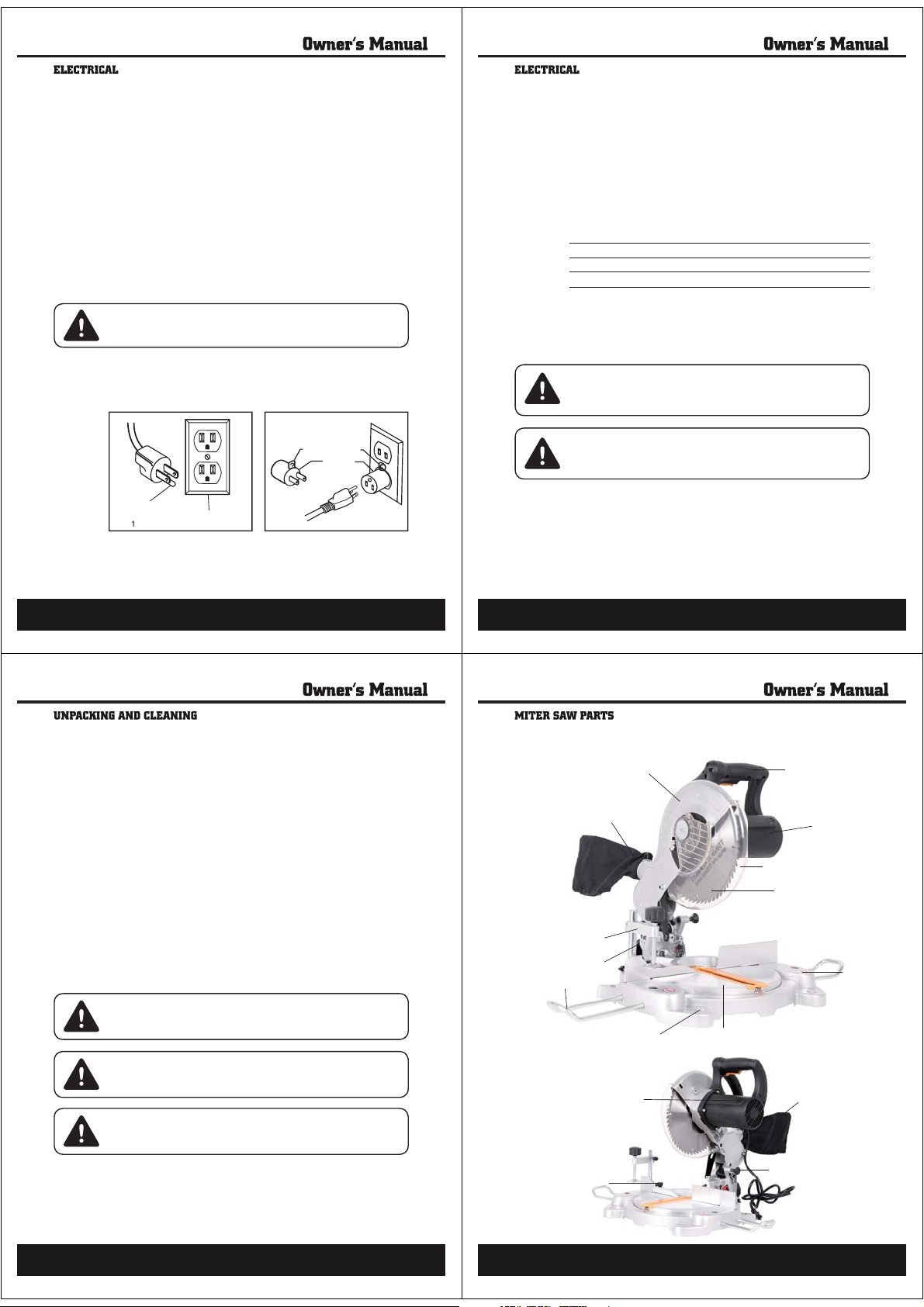
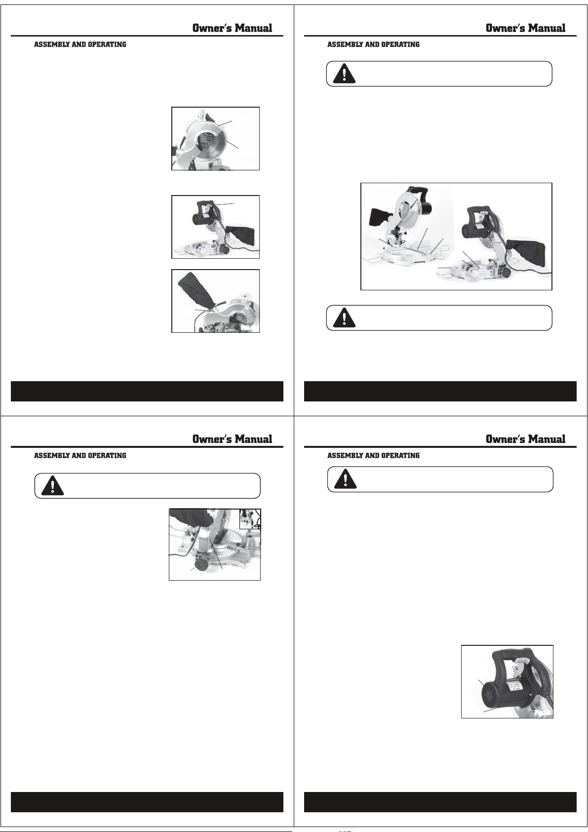
Upper Blade Guard
Dust Extraction Port
Work Clamp
Bevel Lock Wheel
Extension Bar
Bench Mounting Holes
Rotating Table
Main Handle
Motor
Lower Blade Guard
Saw Blade
Base
WARNING!
re to comply could result in accidental starting and serious personal injury.
WARNING! Before moving the saw: Lock the miter lock knob in 45° position.
Lock bevel lock lever. Pull the head assembl
ever carry the tool by the slide rails, this may cause blade damage
ever carry the tool by the cord or head assembly power switch handle. Dam
age to insulation could cause an electric shock. Damage to wire connections
ould
o not connect to power supply until assem
ten the s
e rail lock knob. Lock head assembly in the down position
completely towardyou and
11
s complete.Fa
Carbon Brush Cap
Tab l e Lock Pin
Dust Bag
Head Lock Pin
12
Page 4
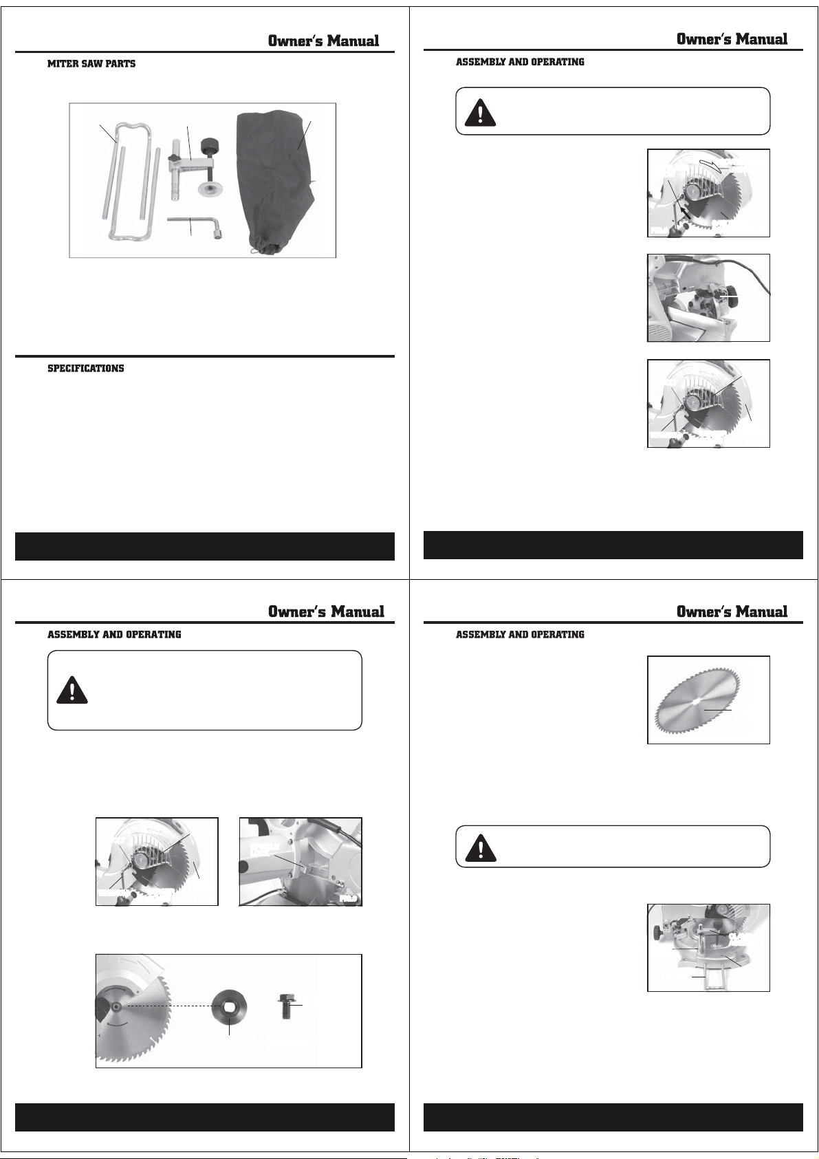
Fig. 4 illustrates all the loose parts packed with the saw.
14
SAFETY RULES
1. When replacing the Saw Blade,
make sure the new Saw Blade has a
diameter of 10”, an RPM rating of
at least 7000, and an arbor hole of
1” diameter.
2. DOWN When installing a Saw Blade,
make sure the teeth of the Saw Blade
point downward, and that the direction of the arrow shown on the Saw
Blade matches the direction of the
arrow shown on the Cover Case. (See
Figure 5.)
3. Lock the Saw Blade in its upward
position. To do so, pull out on the
Cross Pin. Raise and hold the Cover
Case of the Miter Saw fully upward.
Turn the Cross Pin 90 degrees.Then,
insert the Cross Pin into the deep slot
in its locked position. (See Figures 6
and 7)
WARNING! Prior to performing any assembly and/or adjustment procedures,
make sure the Power Cord of the Miter Saw is unplugged from its electrical
outlet. Make sure the unit has completely cooled, and wear heavy-duty work
gloves.
COVER CASE
ARROW
SAW TEETH
POINTING DOWN
SAW BLADE
ARROW
FIG.5
FIG.6
PIN
SCREW
SAFETY
COVER
LARGER
COVER
WRENCH
BOLT
FIG.7
1
2
4
Key No. Description Qty
1 Extension Bar 2
2 Work Clamp 1
3 Dust Bag 1
4 Socket Wrench 1
Rating ..................................................................... 120 V, 60 Hz, AC Only, 15 A
No Load Speed .................................................................................. 4500 /min.
Blade Diameter ............................................................................. 10” (254 mm)
Blade Arbor .................................................................................... 1” (25.4 mm)
Cutting Capacity 90º x 90º .................................................... 2-15/16” x 5-1/3”
90º x 45º...................................................... 2-15/16” x 3-3/4”
45º x 90º.......................................................... 1-1/3” x 5-1/3”
45º x 45º.......................................................... 1-1/3” x 3-3/4”
Net weight ............................................................................................. 24.2 lbs
3
13
CAUTION! The Cross Pin should always be activated in the “locked
down” position when the Saw is not being used and when the Saw is
being transported. The Cross Pin should be activated in the “locked up”
position only when changing Saw Blades. NEVER use the Cross Pin in
any cutting operation. The Cross Pin allows the operator to lock the Saw
Blade in position, preventing the Saw Blade from being raised or lowered. (See
Figures 6 and 7.)
4. Loosen the Screw that holds the Large Cover in place. Then, use the Wrench
to remove the Bolt. (See Figure 8.)
5. Rotate the Large Cover and Safety Cover up and out of the way. (See Figure
8.)
6. Depress the Spindle Lock to keep the Saw Blade from turning. (See Figure
9.)
BOLT
WRENCH
7. Use the Wrench to unscrew and remove the Spindle Bolt. NOTE:The
LARGER
COVER
Spindle Bolt unscrews in a clockwise direction. Then, remove the Outer
Flange. (See Figure 10.)
SCREW
SAFETY
COVER
SPINDLE
LOCK
FIG.8
OUTER FLANGE COUNTERCLOCKWISE
TO TIGHTEN
SPINDLE BOLT
CLOCKWISE
TO LOOSE
FIG.9
FIG.10
8. Release pressure on the Spindle Lock.
(See Figure 9.)
9. Wearing heavy duty work gloves to
avoid accidental cuts, remove the old
Saw Blade. (See Figure 11)
10. Install the new Saw Blade, make
sure the teeth of the Saw Blade
are pointing downward. (See Figure
5)
11. Reassemble the Outer Flange, and
5RKPFNG$QNVſrmly. (See Figure 10)
12. Swing the Large Cover and Safety Cover back in place, make sure the
Safety Cover covers the Saw Blade. (See Figure 8)
SAW
BLADE
FIG.11
13. Reinstall the Bolt, and retighten the Screw. (See Figure 8)
14 . Make sure the Safety Cover returns to its original position prior to operating
the Miter Saw.
CAUTION! Make sure to pull out on the Cross Pin. Turn the Cross Pin 90 degrees. Then, insert the Cross Pin into the shallow slot in its unlocked position.
NEVER use the Cross Pin in any cutting operation. (See Figure 6.)
TO ASSEMBLE ADDITIONAL ACCESSORIES
1. A workpiece Clamp Assembly can
be installed by inserting the Assembly into the hole located in the
Guide Fence. Once inserted, lock the
Assembly in place with the Thumb
Screw.To clamp the workpiece to the
Base of the Miter Saw, turn the Adjusting Knob on the Clamp Assembly
clockwise. (See Figure 12.)
2. A workpiece Holder can be inserted
into each side of the Base, adjusted
for the desired length. The Holders should be used as supports when cutting
longer length workpieces. (See Figure 12.)
GUIDE
FENCE
HOLDER
CLAMP
ASSEMBLY
BASE
FIG.12
15
16
Page 5
TO SAFETY COVER
18
TO ADJUST THE CUTTING DEPTH
1. The depth of cut may be adjusted to a maximum of 5-1/3” at 90, and 3-3/4”
at 45°.
2. Slightly loosen the Screw and pull the Miter Saw’s Cover Case down- ward
as far as it will go. Observe whether the edge of the Saw Blade passes completely through the Kerf Board. (See Figure 16)
3. If the Saw Blade does not pass completely through the Kerf Board, lower the
Saw Blade further by loosening the Screw. (See Figure 16)
4. After adjusting the Screw, press down on the Miter Saw and make sure the
Saw Blade does not contact the bottom of the Table or any other part of the
Saw Base. (See Figure 16)
5. If the Saw Blade touches the Table or any other part of the Saw Base, tighten
the Screw to raise the Saw Blade slightly until it clears. (See Figure 16)
WARNING! Prior to performing this procedure, make sure the Power Cord of
the Miter Saw is unplugged from its electrical outlet.
Fig.16
TO ADJUST THE MITER ANGLE
1. The miter angle of a cut may be adjusted 0 - 45 degrees to the right or left.
To do so, turn the Angle Lock located at the back board. (See Figure 16)
2. While the Angle Lock is turned on, move the Handle to the right or left
until the desired miter angle of cut is indicated by the Gauge located on
the Base.Then, screw down the Angle Lock to lock the Miter Saw in place.
(See Figure 16)
WARNING! Prior to performing this procedure, make sure the Power Cord of
the Miter Saw is unplugged from its electrical outlet.
GAUGE
TABLE
KERF BOARD
BASE
ANGLE LOCK
ANGLE LOCK
1. The transparent Safety Cover automatically rotates to cover the Saw Blade
when the Cover Case is lifted. When the Cover Case is lowered, the Safety
Cover rotates back out of the way. (See Figure 13)
2. Do not disconnect or remove the Safety Cover. Do not operate the Miter Saw
if the Safety Cover is damaged or missing. (See Figure 13)
3. If the transparent Safety Cover becomes so dirty that the Saw Blade cannot
be seen clearly, disconnect the electrical Power Cord from its electrical
outlet and clean the Safety Cover with
a soft, damp, cloth. A mild detergent
may be used, but do not use solvents
which may damage the Safety Cover.
(See Figure 13.)
COVER
CASE
SAFETY
COVER
FIG.13
THE POWER SWITCH
1. Before plugging in the Miter Saw,
check the operation of the Power
Switch. Do not operate the Miter Saw
if the Power Switch is not operating
properly.To turn on the Miter Saw,
simply squeeze the Power Switch.To
turn off the tool, release pressure on
the Power Switch. (See Figure 14.)
THE DUST BAG
1. The Dust Bag catches and holds the
wood chips and saw dust when the
Miter Saw is in operation. (See Figure
15)
2. The outside diameter of the Dust Tube
is 1-3/4” to which the Dust Bag or a
vacuum hose (not included) may be
attached. It is recommended that only
CSWCNKſGFVGEJPKEKCPRGTform this
procedure. (See Figure 15)
DUST
TUBE
POWER
SWITCH
FIG.14
FIG.15
17
TO ADJUST THE BEVEL OF CUT
WARNING! Prior to performing this procedure, make sure the Power Cord
(102) of the Miter Saw is unplugged from its electrical outlet.
1. The bevel angle (or Saw Blade tilt
capacity) may be adjusted from
0 - 45 to the left. To do so, loosen
the wheel located at the rear
of the Miter Saw. (See Figure 17)
2. Tilt the Back Rack until the
desired bevel angle of cut is
achieved as indicated on the
Gauge. Then, re-tighten the
Wheel to lock the Back Rack in
place. (See Figure 17)
BASIC OPERATION
1. Make sure the Power Cord of the Miter Saw is unplugged from its electrical
outlet. Then, if necessary, make adjustments to the workpiece Holder, cutting
depth, miter angle, and bevel angle.
WHEEL
BACK RACK
GAUGE
Fig.17
2. Raise the Saw Blade up to allow positioning of the workpiece.
3. Check to make sure the Power Switch is operating properly.
4. Place the workpiece on the Table and against the Guide Fence.
5. Use the Clamp Assembly to hold the workpiece in place.
6. Plug the Power Cord into the nearest 120 volt, grounded, electrical outlet.
7. Squeeze the Power Switch to turn on the Miter Saw.
8. When the Saw Blade is tur ning at full speed, slowly bring down the Motor
Housing to complete the cut. NOTE: Feed the Saw Blade into the workpiece
gradually. Do not force the machine to remove material faster than it was
designed to cut.
9. When cutting a large wor kpiece, make sure its entire length is properly supported. If necessary, use a roller stand (not included) with a larger workpiece.
10. Never attempt to remove material stuck in the moving parts of the Miter Saw
while it is plugged in and running.
11. Turn off the Miter Saw if the workpiece is to be backed out of an uncompleted cut.
12. When the cut is complete, release the Power Switch to turn off the Miter Saw.
13. Wait until the Saw Blade comes to a complete stop. Raise the Motor Housing. Then, unplug the Power Cord from its electrical outlet.
14. Loosen the Clamp Assembly, and remove the workpiece and scrap material
from the Table.
19
WARNING! Always make sure the Powe r Switch (98) is in its “OFF” position,
and unplug the Powe r Cord from its 120 volt electrical outlet before performing
any inspection, adjustments, maintenance, or cleaning.
1. Make sure the power tool is cool to the touch before inspection, maintenance, and cleaning begin. Always protect
gloves.
2. Before each use, inspect the general condition of the Miter Saw. Check for
loose screws, misalignment or binding of moving parts, cracked or broken
parts, damaged electrical wiring, loose, cracked, or bent Saw Blade, and
any other condition that may affect its safe operation. If abnormal noise or
vibration occurs, have the problem corrected before further use. Do not use
damaged equipment. Never work with a dull saw blade.
3. Daily: With a soft brush, cloth, or vacuum, remove all dust and debris from
the Miter Saw.Then, use a premium quality, lightweight machine oil to lubricate all moving parts except the Saw Blade.
4. To replace the Motor Carbon Brushes: It may become necessary at sometime to replace the two Carbon Brushes when the Motor performance
de- creases, or stops working completely.The Carbon Brushes are located
on each side of the Motor Housing. To do so, remove the two Brush Covers.
Then, remove the two Carbon
Brushes are worn down more than 1/2, replace both Carbon Brushes. If,
however, the Carbon Brushes are just dirty they may be cleaned by rubbing
them with a pencil eraser.When installing the Carbon Br ushes, make sure
the carbon portion of the Carbon Brushes contact
that the springs face away from the
Motor. Also, make sure the springs
operate freely. After cleaning or replacement, replace the Brush Holders. NOTE: New Carbon Brushes
tend to arc or sparNZKHQÀUVWXVHG
until they wear and conform to the
Motor’s Armature. (See Figure 18)
5. NOTE: With
Steps #1, #2, #3, and #4 all other
maintenance and servicing should
be performed only b\DTXDOLÀHG
service technician.
the exceptions of
Brushes from the Brush Holders. If the Carbon
your hands by wearing wor k
the Motor Armature, and
CARBON
BRUSH
(NOT SHOWN)
CARBON
BRUSH
Fig.18
20
Page 6
W
ARNING!
f
d
.
W
g
k.
W
-
e
g
O
O
.
r
.
ſ
.
Tigh
igh
W
.
.
to provide smooth functioning. To prevent work from slipping during cutting
.
bl
h.
OT
use any aerosol or
W
-
U
ON
ion.
l.
.
PLlEASE READ THE FOLLllOWING CAREFULLllY
The manufacturer and/or distributor has provided the parts list and assembly
diagram in this manual as a reference tool only. Neither the manufacturer or distributor makes any representation or warranty of any kind to the buyer that he or
UJGKUSWCNKſGFVQOCke an[TGRCKTUVQVJGRTQFWEVQTVJCVJGQTUJGKUSWCNKſGF
to replace any parts of the product. In fact, the manufacturer and/or distributor
expressly states that all repairs and parts replacements should be undertaken
by cerVKſGFCPFNKEGPUGFVGEJPKEKCPs, and not by the buyer.The buyer assumes
all risk and liability arising out of his or her repairs to the original product or
replacement parts thereto, or arising out of his or her installation of replacement
parts thereto.
manu
pro
ARNING!Always wear safety goggles or safety glasses with side shields
durin
ear a dust mas
ARNING! Before performing any maintenance, make sure the tool is un
plugged from the power supply and the switch is in the “OFF” position. Failur
o heed this warning could result in serious personal injury.
CARBON BRUSHES
See Fig. 19.
The brushes and commutator in your
tool have been engineered for many
hours of dependable service. To maintain peak efſciency of the motor, we
recommend every two to six months
the brushes be examined.
Motor Brush Replacement
To inspect or replace brushes:
1. Unplug the saw.
en servicing, use only replacement parts recommended by the
acturer of this tool. Use of any other parts may create a hazard or cause
uct damage
power tool operation or when blowing dust. If operation is dusty, also
BRUSH CAP
Fig.19
ENERAL MAINTENANCE
dition. Make sure the table insert is in good condition and in position
. Clean your cutting tools with a gum and pitch remover
operations, DO NOTwax the workingface of the miter gauge
5. Protect the saw blade by cleaning out sawdust from underneath the saw
e and in the blade teeth. Use a resin solvent on the blade teet
ta
ARNING!
products, penetrating oils, etc., come in contact with the plastic parts. Chemi
DO N
personal injury.
BRICATI
L
This saw’s motor bearings have been packed at the factory with proper lubricat
pitch remova
blade guard assembly and miter gauge)
ARNING!
2. Remove the brush cap on the motor usin
3. Pull out the brush. Repeat for the opposite side.
4. Inspect the brushes for wear. On the wide ƀat side of the brush is a wea
. Install the new brush.The two tabs on the brush terminal go in the same
.
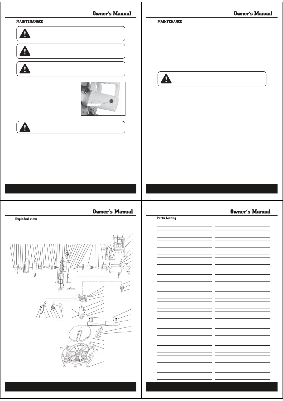
3245687 9 10 11 12 13 14 15 16 17 18 19 22 21 22 23 24 25 26 27 28 29 30 31 32 33 34 35 36 37 38 39 40 41 42 43 44
1
90 89 88 87 86 85 84 83
e brush cap is spring loaded by the brush assembly.
a wide ƀat blade screwdriver.
TE: If installing the existing brush or brushes, make sure the brush goes
N
in the same way it came out.
educe motor performance and increase brush wear
limit line. If the brush contact face is at or beyond (no line visible) the limit
eplace brushes as a set
hole the carbon part
ten the brush cap but do not overt
therwise a break-in period will occur that will
ts into
79
78
ten.
82
81
80
59
60
61
62
63
64
65
66
67
73
74
75
76
77
45 46 47 48
APA Parts No. No. Description QTY APA Parts No. No. Description QTY
SCREW (M5X20) 1
PB113 -01-ZY
PB113 -02-ZY
PB113 -03-ZY
49
50
51
52
53
54
55
56
57
58
68
69
70
71
72
PB113 -04-ZY
PB113 -05-ZY
PB113 -06-ZY
PB113 -07-ZY
PB113 -08-ZY
PB113 -09-ZY
PB113 -10-ZY
PB113 -11-ZY
PB113 -12-ZY
PB113 -13-ZY
PB113 -14-ZY
PB113 -15-ZY
PB113 -16-ZY
PB113 -17-ZY
PB113 -18-ZY
PB113 -19-ZY
PB113 -20-ZY
PB113 -21-ZY
PB113 -22-ZY
PB113 -23-ZY
PB113 -24-ZY
PB113 -25-ZY
PB113 -26-ZY
PB113 -27-ZY
PB113 -28-ZY
PB113 -29-ZY
PB113 -30-ZY
PB113 -31-ZY
PB113 -32-ZY
PB113 -33-ZY
PB113 -34-ZY
PB113 -35-ZY
PB113 -36-ZY
PB113 -37-ZY
PB113 -38-ZY 38
PB113 -39-ZY
PB113 -40-ZY
PB113 -41-ZY
PB113 -42-ZY
PB113 -43-ZY
PB113 -44-ZY
PB113 -45-ZY
01
SOCKET HEAD SCREW M8X12
02 1
BIG WASHER
03
SCREW M6X12
04
LOCATING PLATE
05
SPRING
06
WASHER
07
GUARD COVER
08
PRESSBOARD SCREW M8X16-L
09
UPPER PRESSBOARD
10
SAW BLADE
11
LOWER PRESSBOARD
12
SCREW M6X12
13
BEARING PRESSBOARD
14
OUTPUT SPINDLE
15
WOODRUFF KEY 1
16
BEARING 6203 1
17
GEAR BOX COVER 1
18
BIG GEAR 1
19
CIRCLIP FOR SHAFT ĭ17
20
SCREW M4X10 2
21
SLIDING BEARING 1
22
BIG SPRING 1
23
STRETCHING SCREW 1
24
SAW COVER 1
25
LOCKNUT M6 1
26
CONTROL KNOB 1
27
SPRING 1
28
SCREW 1
29
CONTROL KNOB SEAT 1
30
SCREW M5X14 2
31
BEARING 6201 1
32
SCREW M4X10 1
33
SELFT-LOCKING PRESSBOARD 1
34
SPRING 1
35
SELF-LOCKING POLE 1
36
ROTOR 1
37
BEARING 629 1
BEARING COVER 1
39
STATOR
40 1
41
HANDLE 1
42
HANDLE 2
SELF-TAPPING SCREW ST4X20
43
44
SELF-TAPPING SCREW ST4X20
45
HANDLE 3
PB113 -46-ZY
PB113 -47-ZY
PB113 -48-ZY
1
PB113 -49-ZY
1
PB113 -50-ZY
1
PB113 -51-ZY
1
PB113 -52-ZY
1
PB113 -53-ZY
1
PB113 -54-ZY
1
PB113 -55-ZY
1
PB113 -56-ZY
1
PB113 -57-ZY
1
PB113 -58-ZY
2
PB113 -59-ZY
1
PB113 -60-ZY
1
PB113 -61-ZY
PB113 -62-ZY
PB113 -63-ZY
PB113 -64-ZY
PB113 -65-ZY
1
PB113 -66-ZY
PB113 -67-ZY
PB113 -68-ZY
PB113 -69-ZY
PB113 -70-ZY
PB113 -71-ZY
PB113 -72-ZY
PB113 -73-ZY
PB113 -74-ZY
PB113 -75-ZY
PB113 -76-ZY76BASE 1
PB113 -77-ZY
PB113 -78-ZY 78 LOCKNUT M6 1
PB113 -79-ZY
PB113 -80-ZY
PB113 -81-ZY 81 SCREW & COVER 2
PB113 -82-ZY82HANDSPIKE 1
PB113 -83-ZY83BATTERY COVER 1
PB113 -84-ZY
PB113 -85-ZY 85
1
PB113 -86-ZY 86 BATTERY COVER SCREW 2
1
PB113 -87-ZY 87 CABLE JACKET 1
8
PB113 -88-ZY 88 CABLE 1
3
PB113 -89-ZY 89 CABLE PRESSBOARD 1
1
PB113 -90-ZY 90 CABLE PRESSBOARD SCREW 2
SWITCH
46
CAPACITANCE 0.33UF
47
48
HANDLE 4
49
SELF-TAPPING SCREW ST4X14
50
BRUSH HOLDER CAP
51
CARBON BRUSH
52
BRUSH HOLDER
53
HOUSE
54
SCREW M6X30 4
PLANE WASHER 4
55
SCREW M5X12 1
56
HANDLE OF BENDED ARM 1
57
SCREW
58
SHAFT 1
59
O-RING ĭ6.7X ĭ1.8
60
LOCKING SHAFT KNOB 1
61
BENDED ARM 1
62
SCREW M8X30 3
63
NUT M6 1
64
BENDED ARM FINGER 1
65
SCREW M5X8 1
66
67
BASE OF BENDED ARM 1
SCREW M12X21 2
68
SOCKET HEAD SCREW M8X30 2
69
70
BACKBOARD 1
SUNK SCREW M4X10 5
71
72
PROTECTIVE BOARD FOR SAW BLADE 1
73
SWIVEL TABLE 1
SCREW 1
74
FINGER 1
75
77 FOUNDATION 6
79 STRETCHING SCREW M6X20 1
80 SPINDLE 1
84 LASER 1
LASER HOLDER 1
1
1
1
2
2
2
2
1
1
1
Page 7
Steele® warrants to the original purchaser who uses the product in a consumer application (personal,
Merchandise sold by Steele® which has been manufactured by and identified as the product of another
company, such as gasoline engines. The product manufacturer’s warranty, if any, will apply.
ANY INCIDENTAL, INDIRECT OR CONSEQUENTIAL LOSS, DAMAGE, OR EXPENSE THAT MAY RESULT
FROM ANY DEFECTS, FAILURE OR MALFUNCTION OF THE PRODUCT IS NOT COVERED BY THIS
WARRANTY. Some states do not allow the exclusion, so it may not apply to you.
IMPLIED WARRANTIES, INCLUDING THOSE OF MERCHANTABILITY OR FITNESS FOR A PARTICULAR
PURPOSE, ARE LIMITED TO ONE YEAR FROM THE DATE OF ORIGINAL PURCHASE. Some states do not
allow limitations on how long an implied warranty lasts, so the above limitations may not apply to you.
26
residential or household usage) that all products covered under this warranty are free from defects in
material and workmanship for one year from the date of purchase. All products covered by this limited
warranty which are used in commercial applications (i.e. income producing) are warranted to be free of
defects in material and workmanship for 90 days from the date of original purchase. Products covered
under this warranty include air compressors, tools, service parts, pressure washers and generators.
Steele® will repair or replace, at Steele®’s sole option, products or components which have failed within
the warranty period. Service will be scheduled accor
the service center location, and the availability of replacement parts. All decisions of Steele® with regard
to this limited warranty shall be final.
This warranty gives you specific legal rights, and you may also have other rights which vary from state to
state.
RESPONSIBILITY OF ORIGINAL PURCHASER (initial User):
To process a warranty claim on this product, DO NOT return item to the retailer. The product must be
evaluated by an Authorized Warranty Service Center. For the location of the nearest Authorized Warranty
Service Center contact the retailer or place of purchase.
Retain original cash register sales receipt as proof of purchase for warranty to work.
Use reasonable care in the operation and maintenance of the
Manual(s).
Deliver or ship the product to the Authorized Warranty Service Center. Freight costs, if any must be paid
by the purchaser. If the purchaser does not receive satisfactory results form the Authorized Warranty
Service Center, the purchaser should contact Steele® toll free 888-896-6881.
THIS WARRANTY DOES NOT COVER:
Merchandise sold as reconditioned, used as rental equipment, or floor or display models.
Merchandise that has become damaged or inoperative because of ordinary wear, misuse, cold, heat, rain,
excessive humidity, freeze damage, use of improper chemicals, negligence, accident, failure to operate the
product in accordance with the instructions provided in the Owner’s Manual(s) supplied with
improper maintenance, the use of accessories or attachments not recommended by Steele®, or
unauthorized repair or alterations.
Repair and transportation costs of merchandise determine not to be defective.
Costs associated with assembly, required oil, adjustments or other installation and start-up costs.
Expendable parts or accessories supplied with the product which are expected to become inoperative or
unusable after a reasonable period of use.
ding to the normal work flow and business hours at
product as described in the Owner’s
the product,
25
27
 Loading...