

Page 1

CONTENTS
Product Specifications . . . . . . . . . . . . . . . . . . . . . . . . . . . . . . . . . . . . . . . . . . . . . . . . . . . . . . . . . . . 1
Description. . . . . . . . . . . . . . . . . . . . . . . . . . . . . . . . . . . . . . . . . . . . . . . . . . . . . . . . . . . . . . . . . . . . . 1
General Safety Information . . . . . . . . . . . . . . . . . . . . . . . . . . . . . . . . . . . . . . . . . . . . . . . . . . . . . . . . 2
Specific Safety Rules For The Bench Grinder . . . . . . . . . . . . . . . . . . . . . . . . . . . . . . . . . . . . . . . . . . 3
General Safety Information . . . . . . . . . . . . . . . . . . . . . . . . . . . . . . . . . . . . . . . . . . . . . . . . . . . . . . . . 4
Assembly And Installation . . . . . . . . . . . . . . . . . . . . . . . . . . . . . . . . . . . . . . . . . . . . . . . . . . . . . . . . . 6
Troubleshooting . . . . . . . . . . . . . . . . . . . . . . . . . . . . . . . . . . . . . . . . . . . . . . . . . . . . . . . . . . . . . . . . 9
Wiring Diagram and Know Your Bench Grinder . . . . . . . . . . . . . . . . . . . . . . . . . . . . . . . . . . . . . . . . 10
Parts and List . . . . . . . . . . . . . . . . . . . . . . . . . . . . . . . . . . . . . . . . . . . . . . . . . . . . . . . . . . . . . . . . . . 11
Warranty
. . . . . . . . . . . . . . . . . . . . . . . . . . . . . . . . . . . . . . . . . . . . . . . . . . . . . . . . . . . . . . . . . . . . . 13
PRODUCT SPECIFICATIONS
MODEL WHEEL
Rating Voltage 120 Vac
Frequency 60Hz
Amperes 4.8
No Load Speed 3450 RPM
Weight 38 lbs
HP 3/4
Diameter 8 in.
Face 1 in.
Hole 5/8 in.
WORK LIGHT
Rating Voltage 12V
Watt 10W
Base Cast Iron
WARNING! To Reduce The Risk Of Injury, User
Must Read And Understand Instruction Manual.
DESCRIPTION
Unique design with 2 fixed work light to illuminate your work area; Dry double end grinding wheels
can give rapid sharpening to various types of blades. Powerful motor quickly brings the coarse
and fine grinding wheels to their required operating speed.
WARNING
serious personal injury, assemble all parts to your bench grinder before connecting it to power
supply. The bench grinder should never be connected to power supply when you are assembling
parts, making adjustments, installing or removing grinding wheels, cleaning, or when not in use.
To prevent accidental starting or electrical shock that could cause possible
1
Page 2
GENERAL SAFETY INFORMATION
To operate this tool, read this instruction manual and all the labels affixed to the bench grinder carefully
before using. Keep this manual available for future reference. Safety is a combination of common sense,
staying alert and knowing how your bench grinder works.
1. WORK AREA
Keep the work area clean and well lit. Cluttered benches and dark areas invite accidents.Do not use
the tool in explosive atmospheres, such as in the presence of flammable liquids, gases, or dust.
Power tools create sparks which may ignite the dust or fumes.Keep bystanders, visitors, and children
away while operating a power tool. Distractions can cause you to lose control.
2. ELECTRICAL SAFETY
Grounded tools must be plugged into an outlet properly installed and grounded in accordance with
all codes and ordinances. Never remove the grounding prong or modify the plug in any way. Do not
use any adapter plugs. Check with a qualified electrician if you are in doubt as to whether the outlet
is properly grounded. If the tool electrically malfunctions or breaks down, grounding provides a low
resistance path to carry electricity away from the user. Avoid contact with grounded surfaces such
as pipes, radiators, ranges, and refrigerators. There is an increased risk of electrical shock if your
body is grounded.Do not expose power tools to rain or wet conditions. Water entering a power tool
will increase the risk of electric shock.
Do not abuse the cord. Never use the cord to carry the tool or pull the plug from an outlet. Keep
the cord away from heat, oil, sharp edges or moving parts. Replace damaged cords immediately.
Damaged cords increase the risk of electric shock.
When operating a power tool outside, use an outdoor extension cord marked "W-A" or "W'. These
cords are rated for outdoor use and reduce the risk of electric shock.
3. PERSONAL SAFETY
Stay alert, watch what you are doing, and use common sense when operating a power tool. Do not
use the tool when you are tired or under the influence of drugs, alcohol, or medication. A moment
of inattention while operating power tools may result in serious personal injury Dress properly. Do
not wear loose clothing or jewelry. Wear protective hair netting to contain long hair. Keep your hair,
clothing, and gloves away from moving parts. Rubber gloves and non-skid footwear are recommended
when working outdoors.
Avoid accidental starting. Make sure the switch is off before plugging in. Carrying tools with your
finger on the switch or plugging in tools that have the switch on invites accidents.
Remove adjusting keys or switches before turning the tool on. A wrench or a key that is left attached
to a rotating part of the tool may result in personal injury. Do not overreach. Keep proper footing
and balance at all times. Proper footing and balance enables better control of the tool in unexpected
situations. Use safety equipment. Always wear eye protection. Dust mask, non-skid safety shoes,
hard hat, or hearing protection must be used for appropriate conditions.
4. TOOL USE AND CARE
Do not force the tool. Use the correct tool for your application.Do not use the tool if the switch does
not turn it on or off. Any tool that cannot be controlled with the switch is dangerous and must be
repaired. Disconnect the plug from the power source before making any adjustments, changing
accessories or storing the tool. Such preventive safety measures reduce the risk of starting the tool
accidentally. Store idle tools out of reach of children and other untrained persons.
GENERAL SAFETY INFORMATION
Tools are dangerous in the hands of untrained users. Maintain tools with care. Keep cutting tools
sharp and clean. Properly maintained tools with sharp cutting edges are less likely to bind and are
easier to control.Check for misalignment or jamming of moving parts, breakage of parts and any
other condition that may affect the tools operation. If damaged, have the tool serviced before using.
Many accidents are caused by poorly maintained tools.
Use only accessories that are recommended by the manufacturer for your model. Accessories that
may be suitable for one tool, may become hazardous when used on another tool.
5. SERVICE
Tool service must be performed only by qualified repair personnel.Service or maintenance performed
by unqualified personnel could result in a risk of injury. When servicing a tool, use only identical
replacement parts Follow instructions in the Maintenance section of this manual. Use of unauthorized
parts or failure to follow maintenance instructions may create a risk of electric shock or injury.Some
dust created by power grinding contains chemicals that may cause cancer, birth defects, or other
reproductive harm. Some examples of these chemicals are: Lead from lead-based paint Crystalline
silica from bricks, cement, and other masonry products Arsenic and chromium from chemically
treated lumber To reduce your exposure to these chemicals: work in a well-ventilated area, use
approved safety equipment, and use dust masks that are specially designed to filter out microscopic
particles.
SPECIFIC SAFETY RULES FOR THE BENCH GRINDER
Always use the eye shields, spark arrestors and wear safety goggles with side shields.Use of unauthorized
parts or failure to follow maintenance instructions may create a risk of electric shock or injury. Replace
a cracked grinding wheel immediately. Handle the grinding wheels carefully. When replacing, do not
tighten the spindle nut too tightly, the strain can damage the wheel. The wheel diameter decreases
with use. Adjust the tool rests whenever necessary to maintain a distance of 1/8" or less from the
grinding surface. Adjust the spark arrestors to maintain a 1/16" distance or less from the wheel's surface.
Pieces of stone may be thrown off the rotating wheel when first starting the grinder. Always stand to
one side of the grinder wheel when turning it on, and wait at the side until the wheel is at full speed.
Make sure there is no flammable material near the exhaust chutes. The chute will channel out sparks
and debris.Never apply pressure to the workpiece when the grinding wheel is cold. Allow the wheel to
warm up by applying the workpiece gradually. Never use the grinder without the wheel guards. Keep
fingers away from the wheel. Do not try to cut anything with the grinding wheel. When the wheel is
worn out of round, use a wheel dressing tool to resurface it.
SYMBOLS USED THROUGHOUT THIS MANUAL:
Warns about hazards that may cause minor personal injury or property damage
if ignored.
Warns about hazards that can cause severe personal inJury, death, or major
property damage if ignored.
Warns about hazards that will cause serious personal injury, death, or major
property damage if ignored.
2
3
Page 3
GENERAL SAFETY INFORMATION
GENERAL SAFETY INFORMATION
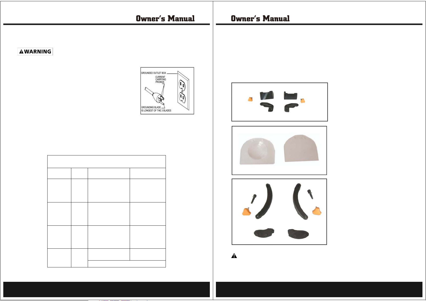
PROPERLY GROUNDED. IF YOU ARE NOT SURE HAVE A QUALIFIED ELECTRICIAN CHECK THE
RECEPTACLE.
DO NOT MODIFY THE PLUG PROVIDED.If it will not fit the outlet,
have the proper outlet installed by an electrician.IMPROPER
CONNECTION of the equipment ground conductor can result
in risk of electric shock. The conductor with the green insulation
(with or without yellow stripes) is the equipment grounding conductor.
If repair or replacement of the electric cord or plug is necessary,
DO NOT connect the equipment grounding conductor to a live terminal
a live terminal
EXTENSION CORDS
Use proper extension cords. Make sure your extension cord is in good condition and is a 3-wire
extension cord which has a 3-prong grounding type plug and matching receptacle which will accept
the machine's plug. When using an extension cord, be sure to use one heavy enough to carry the
current of the machine. An undersized cord will cause a drop in line voltage, resulting in loss of power
and overheating.The table , shows the correct gauge to use depending on the cord length. If in doubt,
use the next heavier gauge. The smaller the gauge number, the heavier the cord.
WARNING: IN ALL CASES, MAKE CERTAIN THE RECEPTACLE IN QUESTION IS
MINIMUM GAUGE EXTENSION CORD
RECOMMENDED SIZES FOR USE WITH STATIONARY ELECTRIC MACHINE~
Ampere Total Length Gauge of
Rating Volts of Cord in Feet Extension Cord
0-6 120
0-6 120 25-50 16 AWG
0-6 120 50-100 16 AWG
0-6 120 100-150 14 AWG
6-10 120
6-10 120 25-50 16 AWG
6-10 120 50-100 14 AWG
6-10 120 100-150 12 AWG
10-12 120
10-12 120 25-50 16 AWG
10-12 120 50-100 14 AWG
10-12 120 100-150 12 AWG
12-16 120
12-16 120 25-50 12 AWG
12-16 120
up to
25
up to
25
up to
25
up to
25
GREATER THAN 50 FEET NOT RECOMMENDED
18 AWG
18 AWG
16 AWG
14 AWG
UNPACKING
After unpacking the unit, inspect all components for any damage that may have occurred in transit.
Read the following precautions and instructions before you attach. Failure to comply with these
instructions could result in personal injury or property damage. Keep these instructions in a convenient
location for future reference.The following items are included with your bench grinder.
Tool Rest (Left & Right) & Adjusting Knob
Eyeshields (Plain & with Magnifier)
Eyeshields Mounting Hardware Kit
WARNING
replaced. Failure to do so could result in possible serious personal injury.Call 888-896-6881
for replacement parts.
lf any parts are missing do not operate this tool until the missing parts are
4
5
Page 4
ASSEMBLY AND INSTALLATION
ASSEMBLY AND INSTALLATION
any assemblyguard.or adjustment. Failure to do so could result in accidental starting and possible
Always disconnect the bench grinderfrom the power source before performing
serious personal injury.
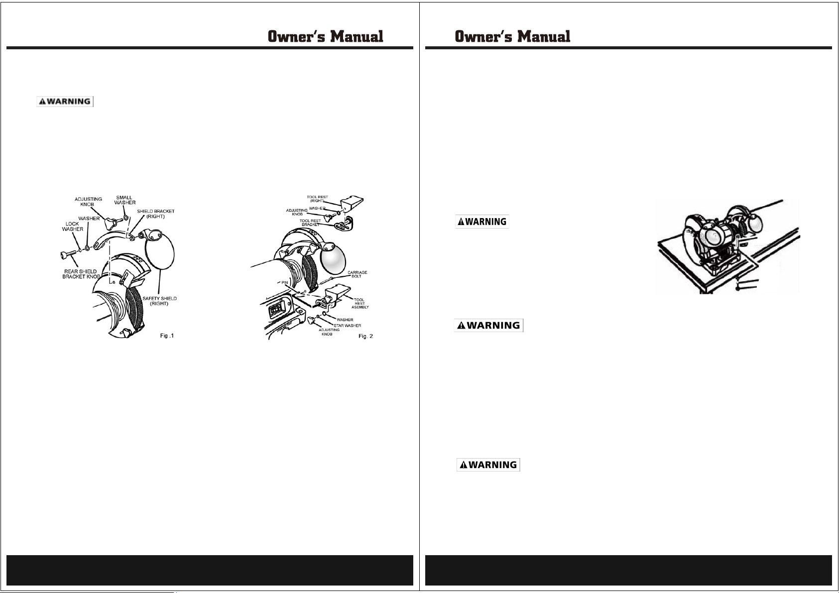
Eyeshield Assembly (Fig 1)
1. Fasten the safety shield to the shield bracket using the adjusting knob and small washer.
NOTE: The slotted part of the safety shield bracket must face towards the grinding wheel guard.
2. Attach the safety shield assembly and bracket to the work wheel guard using a washer, lock washer
and rear shield bracket knob.
Tool rest assembly (Fig 2)
3. Remove the adjusting knob, star washer, and washer from the carriage bolt on the lower portion
of the wheel. (Fig. 2)
4. Using the slotted screw, star washer, washer and adjusting knob, attach the tool rest bracket to
the inside of the wheel guard as shown.
NOTE: The grooved tool rest mounts on the left side.
NOTE: the tool rest bracket’s lower slot must be positioned over the pin on the guard.
With the remaining adjusting knob, install the tool rest to the bracket.
NOTE: Adjust the distance between the wheel and the tool rest to maintain 1/16 in. or less separation
as the diameter of the wheel decreases with use.
INSTALLATION (Fig. 3)
Mounting Grinder To a Work Bench
If grinder is to be used in a permanent location, it should be fastened securely to a firm supporting
surface, such as a workbench.
1. Use 1/4 in. bolts, washers, and nuts (not included). The bolt length should be 1-1/2 in. plus the
thickness of the workbench .
2. Locate and mark the holes where the grinder is to be mounted.
3. Drill four 3/8 in. diameter holes through workbench.
4. Place grinder on workbench, aligning holes in base with holes drilled In workbench.
5. lnsert four 1/4 in. diameter bolts, flat washers, lock washer and attach hex nuts securely.
OPERATION
or safety glasses with side shields during
power tool operation or when blowing dust.
If operation is dusty, wear a dust mask.
If operation is dusty ,wear a dust mask.
To be efficient and work as designed, your tools should
be kept sharp. Dull tools can and will cause
accidents. Bench Grinders are ideal for sharpening tools
such as chisels, planer blades, scissors, etc.,
and for removing rust or corrosion.
1. Eyeshield Adjustment
The see-through eyeshield allows users to see operation clearly and work precisely. Eyeshields can
be adjusted up and down.
2. Tool Rest Adjustment
The appropriate adjustment of tool rests provides the correct working angle to do efficient grinding.
This adjustment can be done by regulating its related adjusting knob. Due to normal wear of the
grinding wheel, it is necessary to adjust the tool rest.
3. Speed Adjustment
The grinder is equipped with a variable speed control knob. When the variable speed control knob
is positioned to the furthermost left position (counter clockwise), the RPM is 2000. The rotation
increases as the knob is turned clockwise. RPM is 3450.
MAINTENANCE
part may create hazard or cause product damage.
General
Keep the bench grinder clean. Frequently remove dust from working parts and beneath the grinder.
Make sure the bench grinder operates properly Frequently check screws , nuts, and bolts for tightness.
NOTE: This bench grinder has made sufficiently lubricated at the factory, therefore, the bench
grinder does not need any additional lubrication during the lifetime of the grinder.
Always wear safety goggles
Fig.3 Mounting grinder to the workbench.
Never sharpen or grind anything made of aluminum.
When servicing, use only identical replacement parts. Use of any other
Hex Bolt
Washer
Washer
Lock
Washer
Hex Nut
6
7
Page 5
ASSEMBLY AND INSTALLATION
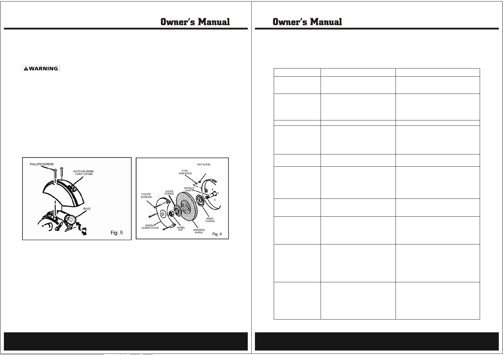
Wheel Replacement (Fig. 4)
adjusting or maintaining the grinder. Do not attempt torepair or maintain the motor electrical
components. This should only be done by aqualified service technician.
If you must replace a grinding wheel, be sure to obtain one with a safe rated speed at least as high as
the "no load speed" RPM marked on the data plate of the grinder.To replace the grinding wheel,
remove the wheel guard cover by loosening the screws, next, loosen the wheel nut in a clockwise
direction for the left side and a counterclockwise direction for the right side. Remove the outer flange
and grinding wheel. To install a new grinding wheel. reverse the above procedure. Be sure the grinding
wheel and outer flange are properly seated on the spindle shaft.
Electric tools used on fiberglass material, wallboard, spackling compounds, or plaster are subject to
accelerated wear and possible premature failure because the fiberglass chips and grindings are highly
abrasive to bearings, brushes, commutators, etc. Consequently, we do not recommended using this
tool for extended work on these types of materials. However, if you do work with any of these materials,
it is extremely important to clean thetool using compressed air.
WORKLIGHT BULB REPLACEMENT (Fig. 5)
1. Unplug the grinder.
2. Remove the two phillips screws from the top of worklight cover.
3. Remove worklight cover.
4. While gently pushing in bulb, turn bulb to left
5. Place new bulb into bulb receptacle and gently push in while turning to the right until bulb is fully
seated.
6. Reinstall the worklight cover using the two phillips screws.
NOTE: To avoid the risk of fire, always use a 12v bulb with wattage no greater than 10w.
Turn the power switch off and remove the plug from the outlet before
to remove.
TROUBLESHOOTING
This section covers the most common problems encountered during operation and what to do about
them. Do not make any adjustments until machine is unplugged and moving parts have come to a
complete stop.
SYMPTOM POSSIBLE CAUSE CORRECTIVE ACTION
Motor will not start.
Motor will not start; fuses 1. Short circuit in line cord or plug. 1. Inspect cord or plug for damaged insulation
or circuit breakers blow
Motor overheats. 1. Reduce load on motor.1. Motor overloaded.
Motor stalls (resulting in
blown fuses or tripped
circuit).
Machine slows when
operating. workpiece into wheel.
Wavy condition on
surface of workpiece.
Lines on surface of
workpiece.
Burning spots or cracks
in the workpiece.
Wheel dulls quickly,
grit falls off.
Wheel clogs and workpiece 1. Wheel is too hard.
shows burn marks select softer bond.2. Feed rate too slow.
2. Open ciruit in motor or loose connections. 2. Inspect all lead connections on motor for loose
2. Short circuit in motor or loose connections.
3. Incorrect fuses or circuit breakers
in power line.
1. Short circuit in motor or loose connections.
2. Low voltage.
3. Incorrect fuses or circuit breakers in
power line.
4. Motor overloaded.
1. Depth of cut too great. 1. Slow down the rate of movement of the
1. Machine vibrating
2. Workpiece not being held firmly.
3. Wheel face uneven.
4. Wheel is too hard.
1. Impurity on wheel surface. 1. Dress the grinding wheel.
2. Workpiece not being held tightly.
1. Improper type of grinding wheel.
2. Improper feed rate.
3. Coolant required.
1. Depth of cut too great.
2. Wheel is soft.
3. Wheel diameter too small.
5. Defective wheel bonding. 3. Replace the wheel.
3. Bad wheel dress.
4. Coolant required.
1. Check power line for proper voltage.1. Low voltage.
or open connections
shorted wires.
2.Inspect all connections on motor for loose or
shorted terminals or worn insulation
3.Install correct fuses or ciruit breakers.
1. Inspect connections on motor for loose or
shorted terminals or worn insulation.
2. Correct the low voltage conditions.
3. Install correct fuses or circuit breakers.
4. Reduce load on motor.
1. Make sure machine s is securely mounted on
a solid surface.
2. Use a holding device to firmly realign the
workpiece
3.Dress the grinding wheel.
4.Use softer wheel,or reduce the feed rate.
2. Use a holding device to firmly retain the
workpiece.
1. Try a wheel which is softer style or a coarser grit.
2. Slow down the rate of movement of the
workpiece into wheel.
3. Add optional coolant system or introduce
a coolant by hand.
1. Slow down the rate of movement of the
workpiece
2. Wheel too soft for the material being ground,
harder bond.4. Bad wheel dress.
4. Dress the wheel.
5. Consult manufacturer of grinding wheel.
1. Wheel too hard for the material being ground,
2. Increase e the rate of movement of the
workpiece e workpiece into wheel.
3. Dress the wheel.
4. Add optional coolant system or introduce
coolant by hand.
8
9
Page 6
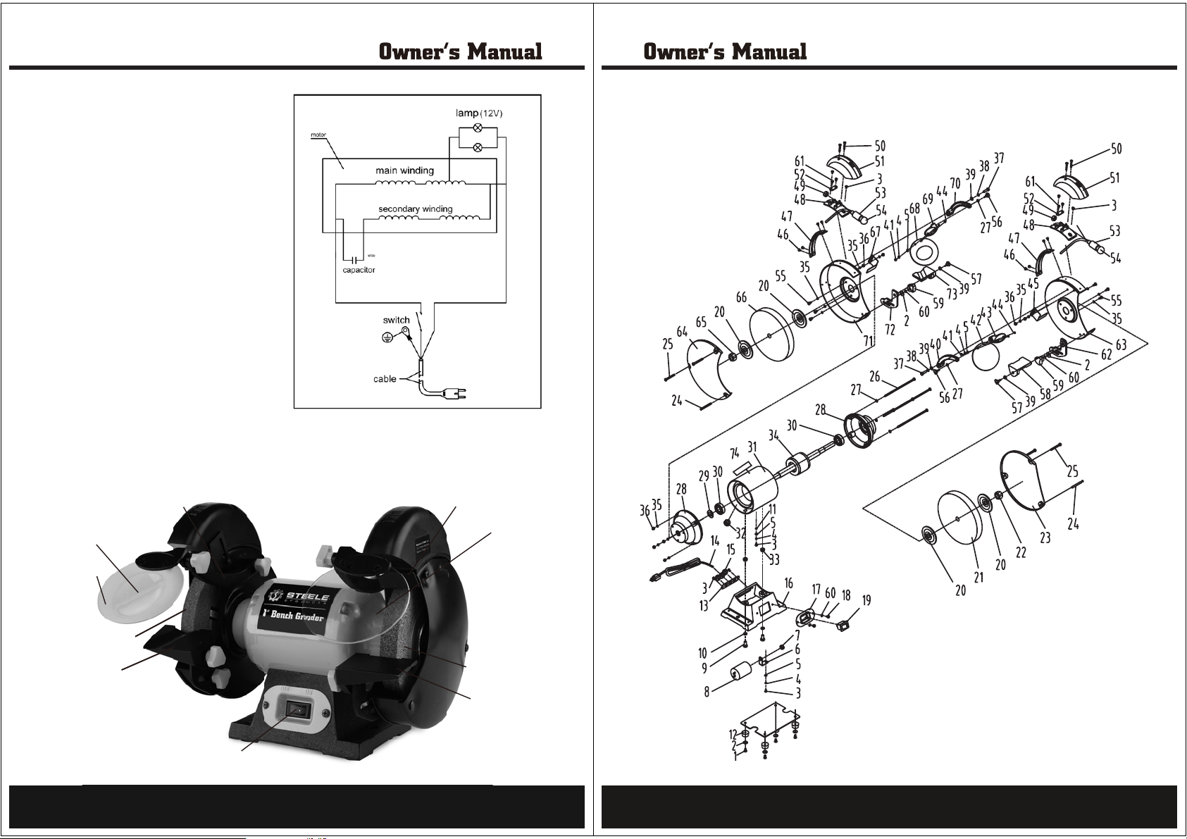
WIRING DIAGRAM
KNOW YOUR BENCH GRINDER
PARTS
MASTERFORCE
Eye Shield Mounting Bracket
Magniłer
Eye Shield
Medium Grinding
Wheel (60 Grit)
Left Tool Rest
ON/OFF Switch
10
Right Spark Guard
Eye Shield
Coarse Grinding
Wheel (36 Grit)
Right Tool Rest
11
Page 7
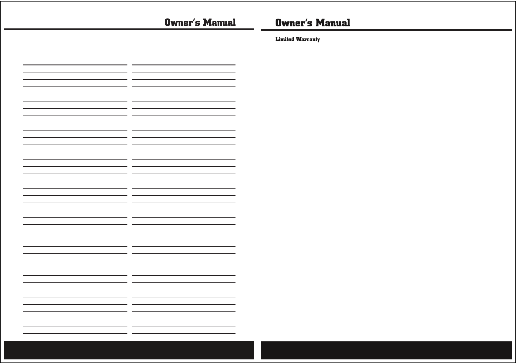
PARTS LIST
APA Parts No. No. Description APA Parts No. No. Description
PHILIPS SCREW (M5x16)
PB008 -01-AW
PB008 -02-AW
PB008 -03-AW
PB008 -04-AW
PB008 -05-AW
PB008 -06-AW
PB008 -07-AW
PB008 -08-AW
PB008 -09-AW
PB008 -10-AW
PB008 -11-AW
PB008 -12-AW
PB008 -13-AW
PB008 -14-AW
PB008 -15-AW
PB008 -16-AW
PB008 -17-AW
PB008 -18-AW
PB008 -19-AW
PB008 -20-AW
PB008 -21-AW
PB008 -22-AW
PB008 -23-AW
PB008 -24-AW
PB008 -25-AW
PB008 -26-AW
PB008 -27-AW
PB008 -28-AW
PB008 -29-AW
PB008 -30-AW
PB008 -31-AW
PB008 -32-AW
PB008 -33-AW
PB008 -34-AW
PB008 -35-AW
PB008 -36-AW
PB008 -37-AW PB008 -74-AW
01 38
BIG WASHER (D5)
02
PHILIPS SCREW (M4x8)
03
STANDARD WASHER(D4)
04
FLAT WASHER (D4)
05
CAPACITOR SUPPORT
06
07
I TYPE HEX NUT (M8)
CAPACITOR
08
HEX BOLT (M8x22)
09
STANDARD WASHER (D8)
10
STAR WASHER (D4)
11
RUBBER BASE
12
POWER CORD CLIP FIX PLATE
13
POWER CORD W/PLUG
14
STRAIN RELIEF
15
BASE
16
SWITCH PLATE
17
PHILIPS SCREW(M5x8)
18
SWITCH (RF1001)
19
WHEEL FLANG
20
36 WHEEL (P200x25x15.88)
21
I TYPE HEX NUT (M16)
22
RIGHT WHEEL GUARD COVER
23
BOLT (M5x51)
24
PHILIPS SCREW(M5x48)
25
PHILIPS SCREW(M5x148)
26
FAT WASHER (D5)
27
END CAP
28
WAVE WASHER (D40)
29
BALL BEARING (180203)
30
STATOR
31
WIRE BUSHING
32
BASE FIXING NUT
33
ROTOR
34
STANDARD SPRING WASHER(D5)
35
I TYPE HEX NUT (M5)
36
HEX BOLT (M6x30)
37
PB008 -38-AW
PB008 -39-AW
PB008 -40-AW
PB008 -41-AW
PB008 -42-AW
PB008 -43-AW
PB008 -44-AW
PB008 -45-AW
PB008 -46-AW
PB008 -47-AW
PB008 -48-AW
PB008 -49-AW
PB008 -50-AW
PB008 -51-AW
PB008 -52-AW
PB008 -53-AW
PB008 -54-AW
PB008 -55-AW
PB008 -56-AW
PB008 -57-AW
PB008 -58-AW
PB008 -59-AW
PB008 -60-AW
PB008 -61-AW
PB008 -62-AW
PB008 -63-AW
PB008 -64-AW
PB008 -65-AW
PB008 -66-AW
PB008 -67-AW
PB008 -68-AW
PB008 -69-AW
PB008 -70-AW
PB008 -71-AW
PB008 -72-AW
PB008 -73-AW
STANDARD SPRING WASHER (D6)
FLAT WASHER(D6)
39
RIGHT EYESHIELD MOUNTING ROD
40
I TYPE HEX NUT (M4)
41
EYESHIELD
42
RIGHT EYESHIELD FIX PLATE
43
PHILIPS SCREW (M4x10)
44
RIGHT SPARK DEFLECTOR
45
PHILIPS SCREW (M4x6)
46
LAMP CORD FIXING PRESS PLATE
47
LAMP BASE
48
PLASTIC NUT
49
PHILIPS SCREW (M4x30)
50
LAMP COVER ASSY
51
LAMP CORD PRESS PLATE
52
LAMP HOLDER
53
BULB
54
PHILIPS SCREW (M5x10)
55
EYESHIELD FIXING KNOB (M5x14)
56
WORK REST FIX KNOB (M6x16)
57
RIGHT WORK REST
58
WORK REST SUPPORT FIX NUT
59
STAR WASHER (D5)
60
PHILIPS SCREW (M4x10)
61
RIGHT WORK REST SUPPORT
62
RIGHT WHEEL GUARD
63
LEFT WHEEL GUARD COVER
64
I TYPE HEX NUT (M16 LEFT)
65
60 WHEEL (P200x25x15.88)
66
LEFT SPARK DEFLECTOR
67
MAGNIFIER
68
LEFT EYESHIELD FIX PLATE
69
LEFT EYESHIELD MOUNTING ROD
70
LEFT WHEEL GUARD
71
LEFT WORK REST SUPPORT
72
LEFT WORK REST
73
LOGO
74
Steele® warrants to the original purchaser who uses the product in a consumer application (personal,
residential or household usage) that all products covered under this warranty are free from defects in
material and workmanship for one year from the date of purchase. All products covered by this limited
warranty which are used in commercial applications (i.e. income producing) are warranted to be free of
defects in material and workmanship for 90 days from the date of original purchase. Products covered under
this warranty include air compressors, tools, service parts, pressure washers and generators.
Steele® will repair or replace, at Steele®’s sole option, products or components which have failed within the
warranty period. Service will be scheduled according to the normal work flow and business hours at the
service center location, and the availability of replacement parts. All decisions of Steele® with regard to this
limited warranty shall be final.
This warranty gives you specific legal rights, and you may also have other rights which vary from state to
state.
RESPONSIBILITY OF ORIGINAL PURCHASER (initial User):
To process a warranty claim on this product, DO NOT return item to the retailer. The product must be
evaluated by an Authorized Warranty Service Center. For the location of the nearest Authorized Warranty
Service Center contact the retailer or place of purchase.
Retain original cash register sales receipt as proof of purchase for warranty to work.
Use reasonabl
e care in the operation and maintenance of the product as described in the Owner’s Manual(s).
Deliver or ship the product to the Authorized Warranty Service Center. Freight costs, if any must be paid by
the purchaser. If the purchaser does not receive satisfactory results form the Authorized Warranty Service
Center, the purchaser should contact Steele® toll free 888-896-6881.
THIS WARRANTY DOES NOT COVER:
Merchandise sold as reconditioned, used as rental equipment, or floor or dis
play models.
Merchandise that has become damaged or inoperative because of ordinary wear, misuse, cold, heat, rain,
excessive humidity, freeze damage, use of improper chemicals, negligence, accident, failure to operate the
product in accordance with the instructions provided in the Owner’s Manual(s) supplied with the product,
improper maintenance, the use of accessories or attachments not recommended by Steele®, or
unauthorized repair or alterations.
Repair and transportation costs of
merchandise determine not to be defective.
Costs associated with assembly, required oil, adjustments or other installation and start-up costs.
Expendable parts or accessories supplied with the product which are expected to become inoperative or
unusable after a reasonable period of use.
12
13
Page 8

Merchandise sold by Steele® which has been manufactured by and identified as the product of another
company, such as gasoline engines. The product manufacturer’s warranty, if any, will apply.
ANY INCIDENTAL, INDIRECT OR CONSEQUENTIAL LOSS, DAMAGE, OR EXPENSE THAT MAY RESULT
FROM ANY DEFECTS, FAILURE OR MALFUNCTION OF THE PRODUCT IS NOT COVERED BY THIS
WARRANTY. Some states do not allow the exclusion, so it may not apply to you.
IMPLIED WARRANTIES, INCLUDING THOSE OF MERCHANTABILITY OR FITNESS FOR A PARTICULAR
PURPOSE, ARE LIMITED TO ONE YEAR FROM THE DATE OF ORIGINAL PURCHASE. Some states do not
allow limitations on how long an implied warranty lasts, so the above limitations may not apply to you.
Distributed by:
730 S.Epperson Dr.
City Of Industry,CA91748
www.steele-products.com
all rights reserved
14
 Loading...