

Page 1
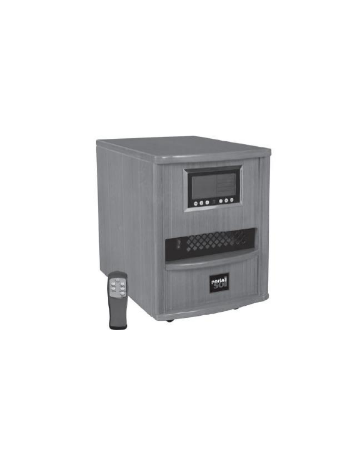
PORTABLE
INFRARED HEATER
SP-HI1500R/RC/RB
Page 2

OPEN BOX AND ASSEMBLY
Porta Del Sol heat packed with:
1. Wood cabinet heater x 1
2. Casters x 4
3. Remote control x 1
4. Battery for Remote x 2
5. User manual x 1
6. Warranty card x 1
SPECIFICATION
Voltage 120V
Frequency 60Hz
Current 13A
Power 1500W
� First, please make sure you have removed all the plastic cover from the
heater cabinet, make sure there is no any project to block air intake and
vent. Reference our safety instruction and heater placement suggestion to
set the heater cabinet.
� Plug into 120V/60Hz 15Amp or higher Amp US standard household
receptacle. Please reference our safety instruction.
� Turned on the master power switch 1
� Front LCD display panel should display you room temperature
� Using remote control “ ?” or Front system control panel to set up. Please
see follow system setup procedure.
CONTROL SYSTEMS OPERATION
Page 3
GENERAL OPERATION
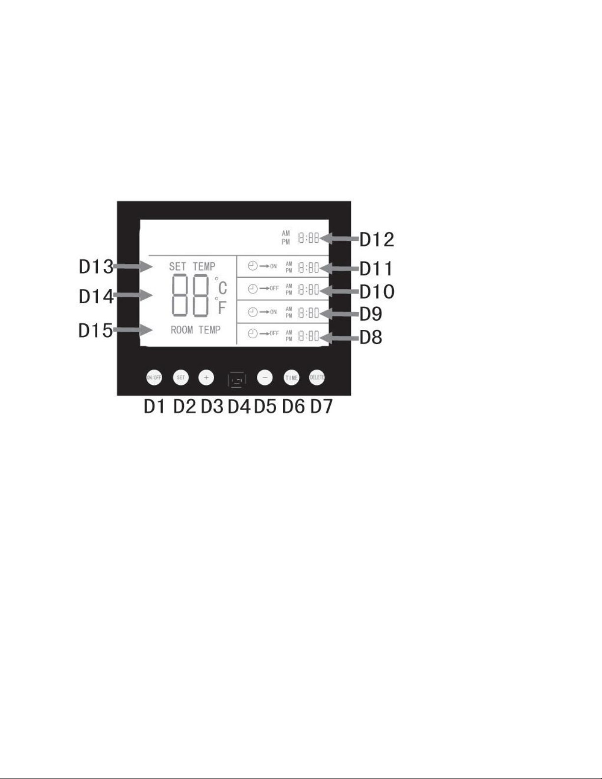
Located on the front of the heater is a control panel / display screen. Simply
press the
POWER ON OFF (D1) button. If using the remote control, simply press the
POWER ON
/OFF (C1) button and the unit will turn on.
CONTROL AND DISPLAY PANEL
(D1) POWER ON/OFF
(D2) CLOCK SET/TIME SET
(D3) INCREASE +
(D4) REMOTE SENSOR
(D5) DECREASE (D6) TIMER SELECT
(D7) TIMER DELETE
(D8) OFF TIMER
(D9) ON TIMER
(D10) OFF TIMER
(D11) ON TIMER
(D12) CLOCK
(D13)SET TEMP.
(D14)TEMPERATURE
(D15) ROOM TEM
REMOTE CONTROL
Page 4
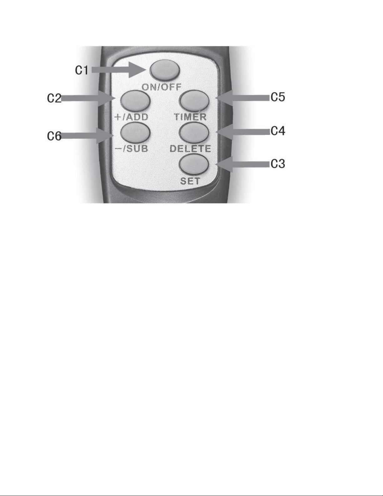
(C1) POWER ON/OFF
(C2) INCREASE +
(C3) CLOCK/TIMER SET
(C4) TIMER DELETE
(C5) TIMER SELECT
(C6) DECREASE –
SET DESIRED TEMPERATURE
To set the desired temperature that you want the heater to maintain, simply press the +
(D3) or the –(D5)button to move the desired set temp up or down. If using the
REMOTE, simply press the (C2) or the (C6) to set the temp. After a few seconds the set
temp display will stop flashing and the heating elements will be turned on. In about one
minute, the fan will be on to delivery warmed air from front vent.
Note: After setting the desired temperature & the displayed digit stops flashing. The
actual room air temperature will be displayed. To check set temperature at any time by
simply press the + or – button on the control panel or remote control.
Once the room temperature reaches the desired setting, the thermostat will maintain
your desired comfort setting by turning the heating elements on and off automatically.
If you do not need the heater to run, simply press the power on/off button (D1 or C1 on
remote) to turn it off.
The fan will continue to run until the heating elements inside cools down.
The heater is equipped with an internal safety switch that cuts off power to the infrared
heating tubes if airflow is blocked to the unit. To restore power to the heating tubes,
remove power cord from wall outlet and let the unit cool down for approximately 20
minutes before plugging power cord back into the wall outlet. Then perform previous
power on procedures. If the heater has cooled sufficiently the safety switch will
automatically reset and the heating tubes will begin to work again.
Page 5

FILTER MAINTENANCE
STATIC FILTER SYSTEM
The Heater Heating System comes equipped with a lifetime washable static
filter which
is easy to clean. The manufacture recommends the filter be cleaned once a
month or as
needed. To do this, follow these steps:
1. Remove the filter from the rear of the unit by remove the screws on the
filter cover.
2. Run warm tap water over the filter, the opposite direction of air flow, until
sufficiently clear or dirt and dust. A small amount of mild detergent may be
used.
3. Shake the filter until excess water is removed.
4. Let dry. Replace the filter to the rear of the unit.
3
Page 6

Part No. Description
HI1500-1 LED Display
HI1500-2 Wooden Shell
HI1500-3 Power Switch
HI1500-4 Zinc Plating Shell
HI1500-5 Zinc Plating(Left)
HI1500-6 Nut
HI1500-7 Duct Fan
HI1500-8 Nut
HI1500-9 Circuit Board
HI1500-10 Self-drilling Screws
HI1500-11 Rear Cover Plate
HI1500-12 Self-drilling Screws
HI1500-13 Screw
HI1500-14 Free Wheel
HI1500-15 Retaining Plate
HI1500-16 Nut
HI1500-17 Zinc Plating(Right)
HI1500-18 Heater Retaining Plate
HI1500-19 Quartzose Heating Tube
HI1500-20 Bellows
HI1500-21 TDS
HI1500-22 Bolt
HI1500-23 Self-drilling Screws
HI1500-24 Air Inlet Fiter Plate
HI1500-25 Self-drilling Screws
HI1500-26 Screw
HI1500-27 Power Cord Bracket
HI1500-28 Circuit Breaker
HI1500-29 Temperature Sensor 1
HI1500-30 Temperature Sensor 2
HI1500-31 Power Cord
HI1500-32 Cord Clamp
HI1500-33 Filter Netting
HI1500-34 Thermostat Connecting Line
HI1500-35 PCB/FPC & LED Connecting Line
HI1500-36 Air Outlet Vestee
HI1500-37 Screws (nether)
HI1500-38 Screws (upper)
Page 7
How to rewire fan control
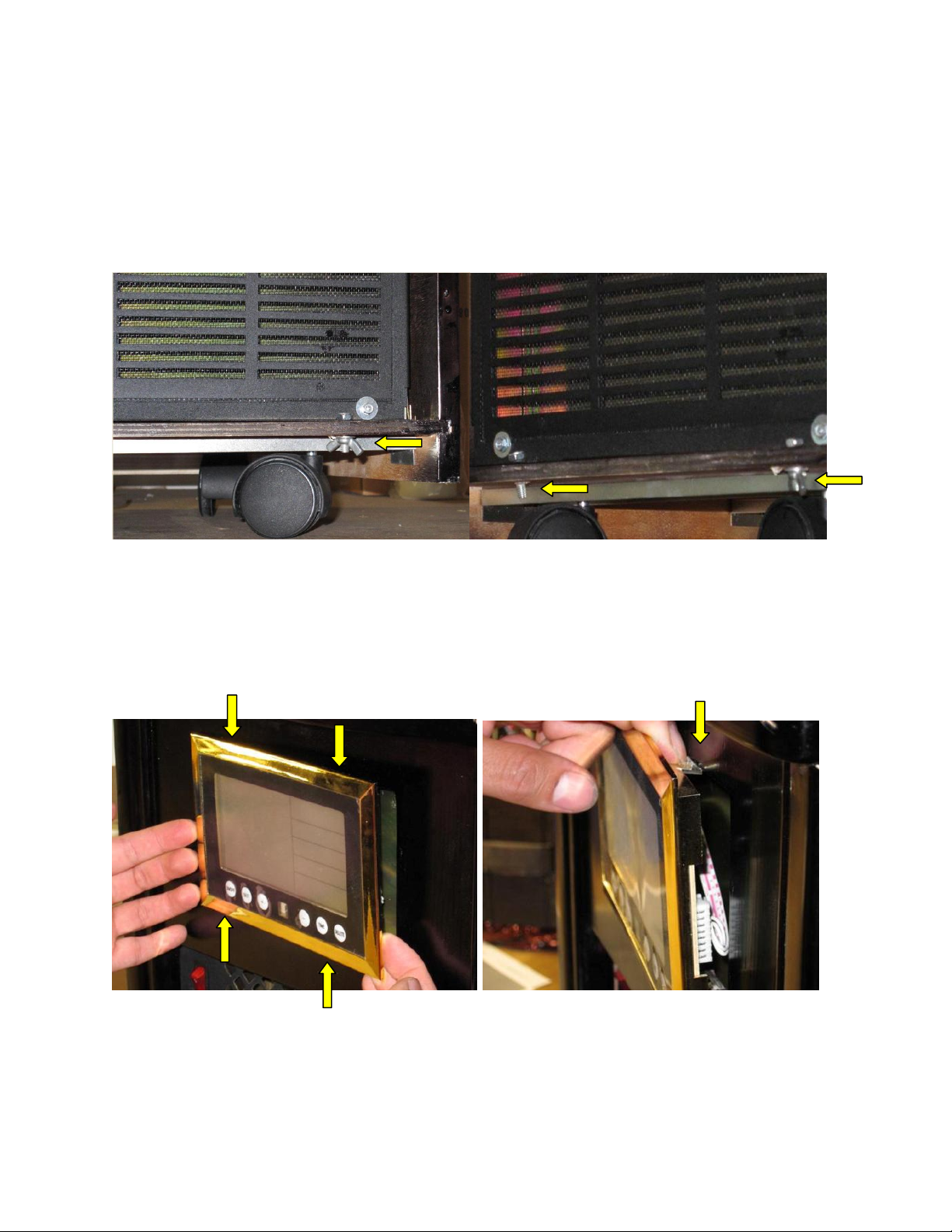
1. Start by removing the back bottom wing nuts on each corner (qty2)
2. Remove Control Panel & Display, this panel has four clips 2 on top and 2 on bottom,
the Control Panel is pressed in. Once loose, place in safe area without removing any
of the wiring.
1
Clip locations
Page 8
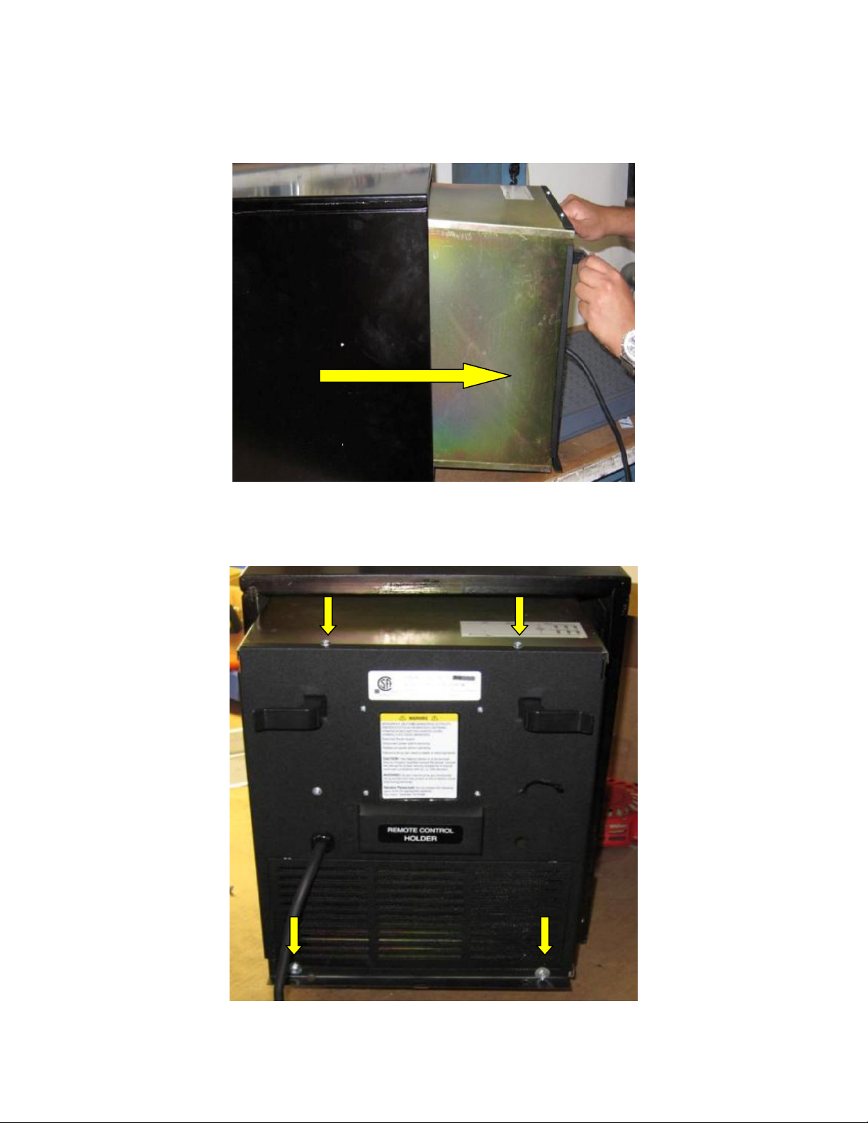
3. Refer back to the other end of the heater and pull gently. Do not to damage the
Control Panel (attached together).
4. Remove the four 6mm screws (Phillips )
Page 9

5. Place the back cover with the control plate down on a flat surface, and cut the
black wire (J2 AC_N) towards the end where the connector is.
Page 10
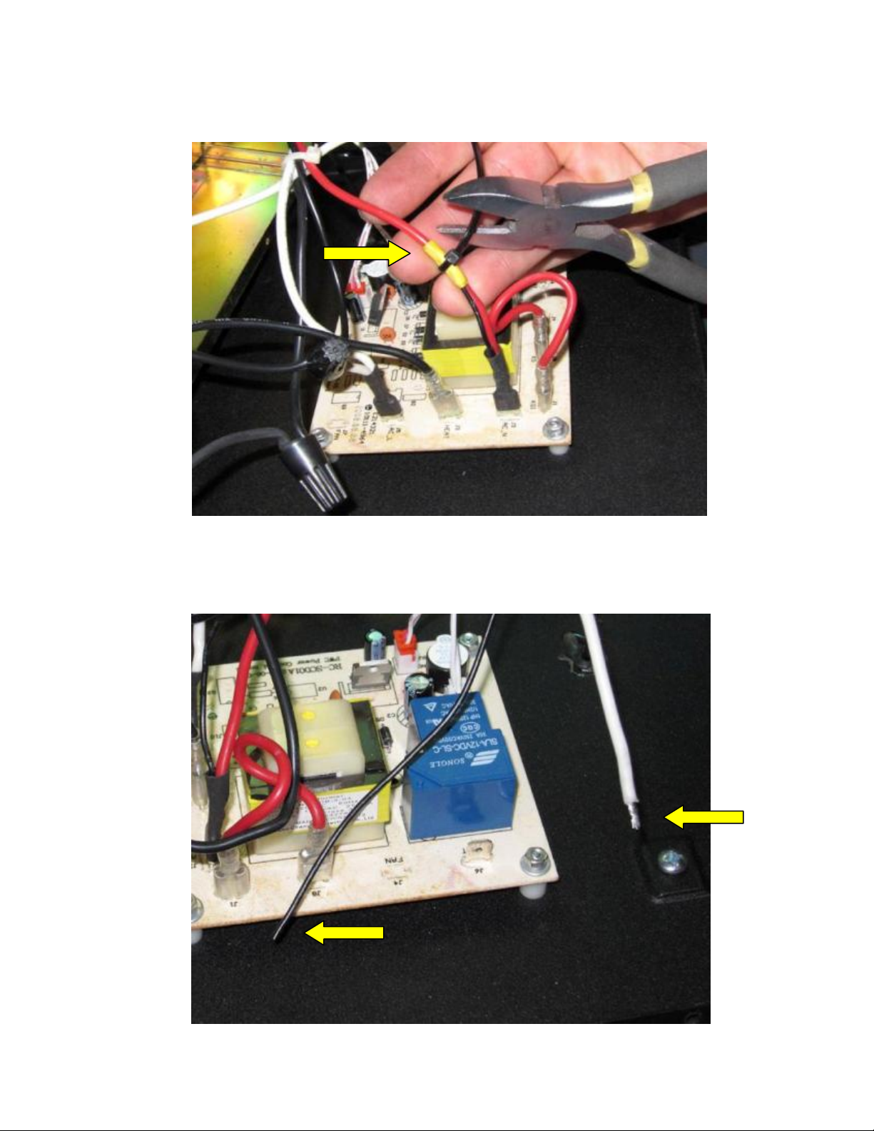
6. Once cut, apply electrical tape and zip tie together to red wire to secure it.
7. A. The loose black wire needs to be attached to the white wire (J6 HEAT)
and make contact (expose wiring on both ends, black and white to meet into
spade connector).
Page 11

B. Push On Terminal used is 16-14.Ga./Cal. 6,35mm (1/4”) Female DisconnectPVC.
C. See picture above for (J6 HEAT) location
Page 12
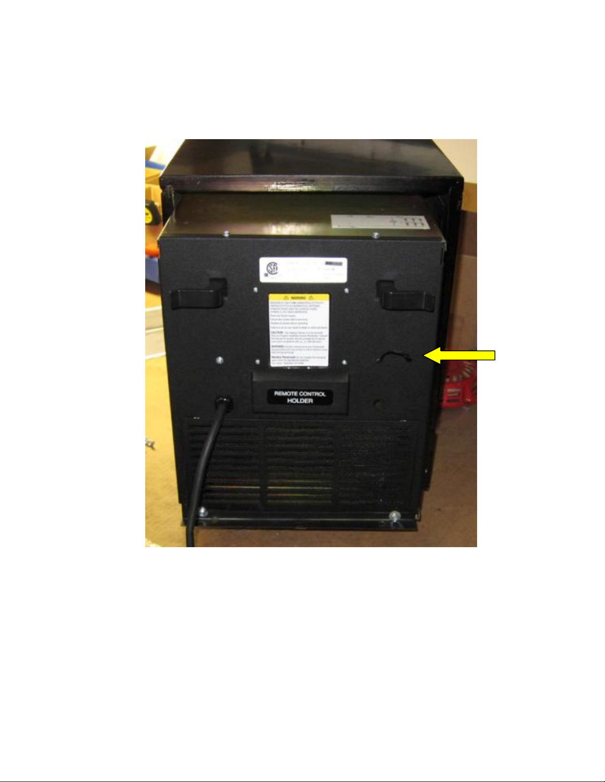
8. Assembly is the reverse of disassembly. Make sure Heat sensor wire on back is
in place thru the outside of the Heater Housing and not in the inside.
 Loading...