

Page 1

RS 232C SERIAL TO PARALLEL
CONVERTER
RS 232C SERIELL-PARALLEL-KONVERTER
RS 232C CONVERTISSEUR SÉRIE
PARALLÈLE
RS 232C CONVERTITORE SERIALE-
PARALLELO
SPC-8K
USERS MANUAL
BEDIENUNGSHANDBUCH
GUIDE D’UTILISATION
MANUALE OPERATIVO
80821621
Page 2

Federal Communications Commission
This equipment has been tested and found to comply with the limits for a Class B digital
device, pursuant to Part 15 of FCC Rules. These limits are designed to provide reasonable
protection against harmful interference in a residential installation. This equipment
generates, uses and can radiate radio frequency energy and, if not installed and used in
accordance with the instructions, may cause harmful interference to radio communications. However, there is no guarantee that interference will not occur in a particular
installation. If this equipment does cause harmful interference to radio or television
reception, which can be determined by turning the equipment off and on, the user is
encouraged to try to correct the interference by one or more of the following measures:
• Reorient or relocate the receiving antenna.
• Increase the separation between the equipment and receiver.
• Connect the equipment to an outlet on a circuit different from that to which the
receiver is connected.
• Consult the dealer or an experienced radio/TV technician for help.
Unauthorized modifications of this product by the user will void his authority to operate
the equipment unless expressly approved by the party responsible for compliance.
For compliance with the Federal Noise Interference Standard, this equipment requires a
shielded cable.
The above statement applies only to printers marketed in the U.S.A.
This digital apparatus does not exceed the Class B limits for radio noise emissions from
digital apparatus set out in the Radio Interference Regulations of the Canadian Department of Communications.
Le présent appareil numérique n’émet pas de bruits radioélectriques dépassant les limites
applicables aux appareils numériques de la classe B prescrites dans le Réglement sur le
brouillage radioélectrique édicté par le Ministère des Communications du Canada.
The above statement applies only to printers marketed in Canada.
VDE Statement
This device carries the VDE RFI protection mark to certify that it meets the radio
interference requirements of the Postal Ordinance No. 243/1991. The additional
marking “Vig. 243/P” expresses in short form that this is a peripheral device (not
operable alone) which only individually meets the Class B RFI requirements in
accordance with the DIN VDE 0878 part 3/11.89 and the Postal Ordinance 243/1991.
If this device is operated in conjunction with other devices within a set-up, in order
to take advantage of a “General (Operating) Authorization” in accordance with the
Postal Ordinance 243/1991, the complete set-up must comply with the Class B limits
in accordance with the DIN VDE 0878 part 3/11.89, as well as satisfy the preconditions in accordance with §2 and the prerequisites in accordance with §3 of the Postal
Ordinance 243/1991.
As a rule, this is only fulfilled when the device is operated in a set-up which has been
type-tested and provided with a VDE RFI protection mark with the additional
marking “Vfg 243”.
Machine Noise Information Ordinance 3. GSGV, January 18, 1991: The sound
pressure level at the operator position is equal to or less than 70 dB (A) according to
ISO 7779.
The above statements apply only to printers marketed in Germany.
Radio Frequency Interference Statement
The Canadian Department of Communications
Statement of
Radio Interference Regulations
Copyright 1990 Star Micronics Co., Ltd.
Page 3

INTRODUCTION
The Serial to Parallel Converter is an EIA compatible serial device that can
interface, STAR Printers with nearly every Micro-Processor which requires
standard EIA (serial) interfacing.
Please read this manual completely before proceeding to “power-up”! This
will ensure successful operation of your Serial to Parallel Converter.
English
Serial Connector
Connect to the Serial
Cable.
Clear Button
Clears the internal
buffer when this button
is pressed.
Parallel Connector
Connect to the printer.
DIP Switch
Sets serial mode.
Refer to the following
section.
In addition to the converter, you will also need a proper serial cable.
Consult with the dealer where you bought your printer if you are unsure about
the type of serial cable you need for your system.
1
Page 4

Connecting the serial-to-parallel converter
• Unplug the printer from its AC power outlet.
• Plug the interface converter’s Centronics connector into the socket on
the side of the printer and secure it in place with the clips.
• Plug one end of a serial cable into the serial connector.
Serial Cable
Serial Connector
• Plug the other end of the serial cable into your computer’s serial ports.
Serial ports are usually marked COM1, COM 2, etc. If your computer
has only one serial port, it will be marked COM1.
Important!
Make sure that the serial-to-parallel converter is resting on a stable,
level surface where it will not be subject to vibration or damage.
Setting the converter’s DIP switches
You should the converter’s DIP switches to they match the settings you make
on your computer. The table to the right shows the parameter that each DIP
switch on the serial-to-parallel converter controls.
2
Page 5

The tables below show all of the settings you can make with the serial-toparallel’s DIP switches to control certain parameters. The tables also
include the matching settings you have to make in your
MS-DOS AUTOEXEC.BAT file or with the Ports option of the Windows
Control Panel. The highlighted cells in the tables indicate default settings
for the serial-to-parallel converter.
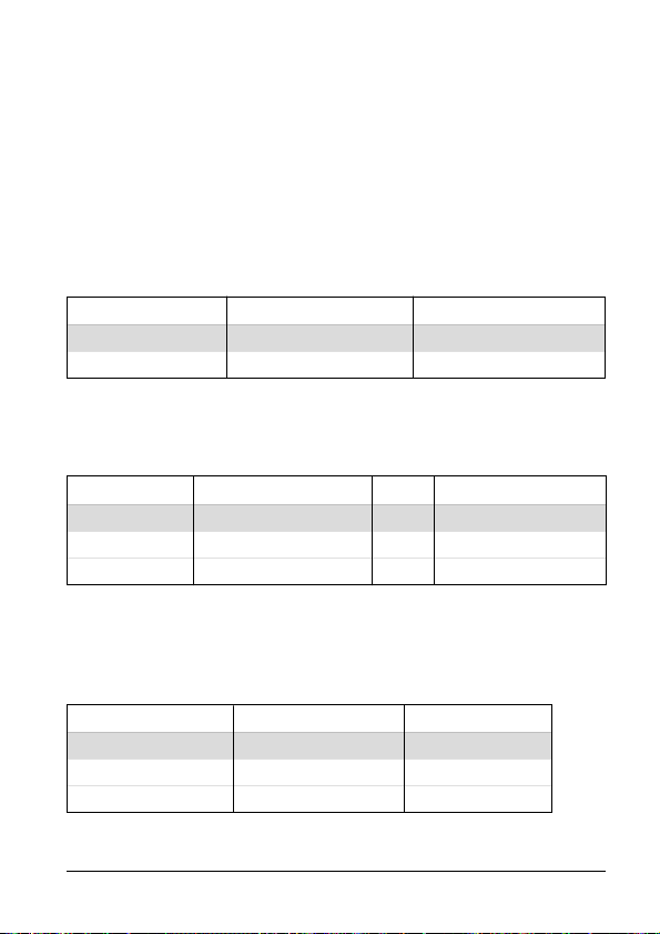
Data Length
Data length is the number of bits that the computer transmits as one unit (byte)
of data. This setting is normally 8.
Switch 1 Data Length DOS/Windows Setting
ON 8 bits 8
OFF 7 bits 7
Parity
Parity is a means of checking for errors in data transmissions.
Switch 2 Switch 5 Parity DOS/Windows Setting
ON ON or OFF None N
OFF ON Odd O
OFF OFF Even E
Protocol
Protocol is the communications convention that is used to allow the printer and
computer to regulate the flow of data. DTR is the most commonly used
protocol.
Switch 3 Switch 4 Protocol
ON ON DTR
ON OFF XON/XOFF
OFF ON ETX/ACK
In serial mode your computer will use one of three protocols to ensure that data
is sent properly. Protocol (also sometimes called “handshaking”) means “who
says what when”, and is the way your printer tells your computer it is ready to
receive data. Your computer and printer communicate by sending protocol
codes (at the start of the ASCII table).
3
Page 6

Some programmers call the XON and XOFF control codes “kiss on and kiss
off”; others call the same protocol DC1 and DC3 (for device control). Either
way, these codes are used to let your printer control the flow of data, telling the
computer when to start and stop sending data. Your printer asks to have data
held back when its memory is nearly full or when it senses an ERROR
condition.
DTR (Data Terminal Ready) protocol does the same thing slightly differently.
The printer sends a continuous high-voltage signal over the cable as long as it
can accept data, but drops the voltage to send a request to the computer to stop
transmitting.
Conversely, it is the computer that controls the data flow with the ETX/ACK
(End-of-text/Acknowledge) protocol. The computer sends an ETX control
code after each string of data, and when the printer receives that code, it sends
an ACK code back to the computer, asking for more. This protocol is less used
by modern computers because it tends not to hold back data when the printer’s
memory gets full.
Baud Rate
Baud rate indicates the speed, in bits per second, at which data is sent to the
printer. The most common setting here is 9600 or 19200.
Switch 6 Switch 7 Switch 8 Baud Rate DOS/Windows Setting
OFF OFF OFF 150 bps 150
OFF OFF ON 300 bps 300
OFF ON OFF 600 bps 600
OFF ON ON 1200 bps 1200
ON OFF OFF 2400 bps 2400
ON OFF ON 4800 bps 4800
ON ON OFF 9600 bps 9600
ON ON ON 19200 bps 19200
Setting up a serial connection on a Windows computer
Remember that the settings you make on your computer must match those you
have made using the converter’s DIP switches.
• In the Windows Program Manager, open the Main group by clicking on
its icon.
4
Page 7

• Double-click on the Control Panel icon.
• Double-click on the Printers icon in the Control Panel window.
• Highlight the STAR printer on LPT1 in the Installed Printers
window, and then click on Connect.
• Click on the serial port (COMn) to which the serial-to-parallel converter
is connected.
• Click OK to return to the Printers window.
• Click Close to return to the Control Panel window.
• Double-click on Ports, and the Ports dialog box appears.
• Click on the name of the port to which the serial-to-parallel converter is
connected.
• Click on Settings.
• Use the pull-down menu or directly type in the appropriate settings for
each of the parameters: Baud Rate, Data Bits, Parity, Stop Bits,
and Flow Control (protocol).
• Click OK to return to the Ports window.
• Click Close to return to the Control Panel window.
Setting up a serial connection on an MS-DOS computer
Remember that the settings you make on your computer must match those you
have made using the converter’s DIP switches.
• Modify your AUTOEXEC.BAT file so that it includes the following
line:
MODE LPT1:=COMn
This line tells the computer to send printer output to the COMn serial
port. The letter n stands for the number 1, 2, etc. You should input
COM1, COM2, etc. to identify the serial port to which the serial-toparallel converter is connected.
• Also add the following line to your AUTOEXEC.BAT file:
MODE COMn:baud, parity, data length, stopbits, p
This line sets up the COMn port according to the parameters you input
for baud, parity, data length, and stopbits. To set up COM2 for
9600 bps, no parity, data length of 8 bits and 1 stop bit, you should input
the following:
MODE COM2:9600,N,8,1,p
The letter “p” at the end of the line tells the computer that the printer will
continually try to re-send data whenever an error occurs. If you need
further information about the MODE command, see your MS-DOS
User’s Guide.
5
Page 8

TECHNICAL SPECIFICATIONS (INPUT SIDE)
General Specifications
Item Specifications
Interface RS-232C-level
Synchronization System Asynchronous
Baud rate 150, 300, 600, 1200, 2400, 4800,
Word length
Start bit: 1 bit
Data bits: 7 or 8 bits (selectable)
Parity bit: Odd, Even or None (selectable)
Stop bits: More than 1 bit length
Signal polarity
Mark: Logic “1” (–3V to –15V)
Space: Logic “0” (+3V to +15V)
Handshaking DTR, XON/XOFF, ETX/ACK
Data buffer 8KB (standard)
Connector Signal and Functional Descriptions
Pin NO. Signal name Direction Function
1 GND –
2 TXD OUT
3 RXD IN
4 RTS OUT
5 CTS —
6NC
7 GND —
8-10 NC
11 RCH OUT
12-19 NC
20 DTR OUT
21-25 NC
9600, 19200 BPS (selectable)
Printer’s chassis ground.
This pin carries data from the printer.
This pin carries data to the printer.
Always Space.
The printer does not check this pin.
Unused.
Signal ground.
Unused.
This line carries the same signal as pin
20.
Unused.
The printer sets this pin to Space when
it is ready to receive data.
Unused.
6
Page 9

EINFÜHRUNG
Der Seriell-Parallel-Konverter ist eine EIA-kompatible serielle Schnittstelle,
die STAR-Drucker mit nahezu jedem Mikroprozessor verbinden kann, der
eine standardisierte (serielle) EIA-Schnittstellenverbindung benötigt.
Bitte lesen Sie dieses Handbuch vollständig durch, bevor Sie die Initialisierung
durchführen. Dies gewährleistet erfolgreiche Arbeit mit Ihrem Seriellen Interface-Konverter.
Serieller Anschluß
Mit dem seriellen
Kabel verbinden.
Löschtaste
Löscht den internen
Puffer, wenn diese
Taste gedrückt wird.
Parallel-Anschluß
Zum Anschließen des
Druckers.
DIP-Schalter
Zum Einstellen der seriellen
Betriebsbedingungen.
Siehe dazu den folgenden
Abschnitt.
Zusätzlich zu diesem Konverter benötigen Sie ein geeignetes serielles
Adapterkabel.
Deutsch
Anschließen des Seriellen Interface-Konverters
• Stecker des Druckers aus der Wandsteckdose herausziehen.
• Centronics-Anschluß des Interface-Konverters in die Buchse, die sich
seitlich am Drucker befindet, einstecken und mit den dazugehörigen
Klammern sichern.
7
Page 10

• Ein Ende des seriellen Kabels in den seriellen Anschluß des Konverters
einstecken.
Serielles Kabel
Serieller Anschluß
• Das andere Ende des seriellen Kabels in den seriellen Ausgang/Anschluß Ihres Computers einstecken. Serielle Ausgänge sind üblicherweise durch COM1, COM2 etc. gekennzeichnet. Wenn Ihr Computer
nur einen seriellen Ausgang hat, so ist dieser mit COM1 gekennzeichnet.
Wichtig!
Vergewissern, daß der Seriell-Parallel-Konverter auf einer festen, ebenen
Unterlage ruht, auf der er keinen Vibrationen und Beschädigungsmöglichkeiten
ausgesetzt ist.
Einstellung der DIP-Schalter des Konverters
Sie sollten die DIP-Schalter des Konverters so einstellen, daß Sie mit den
Einstellungen, die Sie an Ihrem Computer vorgenommen haben, übereinstimmen. Die rechtsstehende Tabelle zeigt die Parameter, die jeder
DIP-Schalter des Seriellen Interface-Konverters steuert.
Die nachstehenden Tabellen zeigen alle Einstellungen, die Sie an den DIPSchaltern des Seriellen Interface-Konverters zur Steuerung bestimmter
8
Page 11

Parameter vornehmen können. Die Tabellen enthalten auch die erforderlichen Einstellungen, die Sie in Ihrer MS-DOS AUTOEXEC.BAT-Datei oder
bei den Anschlußoptionen der Windows-Systemsteuerung vornehmen müssen. Die markierten Kästchen in der Tabelle geben die Standardeinstellungen des Seriellen Interface-Konverters an.
Datenlänge
Die Datenlänge ist die Zahl der Bits, die der Computer als Dateneinheit (Byte)
überträgt. Die Einstellung ist normalerweise 8.
Schalter 1 Datenlänge DOS/Windows-Einstellung
ON(EIN) 8 bits 8
OFF(AUS) 7 bits 7
Parität
Parität ist ein Mittel zur Überprüfung von Fehlern bei der Datenübertragung.
Schalter 2 Schalter 5 Parität
ON(EIN)
OFF(AUS) ON(EIN) Ungerade O
OFF(AUS) OFF(AUS) Gerade E
Protokoll
Protokoll nennt man die Datenaustauschkonvention, die dazu dient, den
Datenfluß zwischen Drucker und Computer zu regulieren. DTR ist das am
häufigsten verwendete Protokoll.
Im seriellen Betrieb benutzt Ihr Computer eines der drei Protokolle, um
sicherzustellen, daß Daten einwandfrei gesendet werden. Protokoll (manchmal auch “handshaking” oder “Quittungsbetrieb” genannt) bedeutet, “Wer
sagt was wann” und ist die Art und Weise, durch die Ihr Drucker mitteilt, daß
Ihr Computer zum Empfang von Daten bereit ist. Ihr Computer und Ihr
Drucker kommunizieren miteinander, indem sie Protokoll-/Steuerbefehle
senden (befinden sich am Anfang der ASCII-Tabelle).
ON(EIN) oder OFF(AUS)
Schalter 3 Schalter 4 Protokoll
ON(EIN) ON(EIN) DTR
ON(EIN) OFF(AUS) XON/XOFF
OFF(AUS) ON(EIN) ETX/ACK
Keine N
DOS/Windows-Einstellung
9
Page 12

Einige der Programme nennen die Steuerbefehle XON und XOFF “kiss on und
kiss off” (mit Kuß einleiten und mit Kuß abschließen”); andere nennen das
gleiche Protokoll DC1 und DC3 (zur Gerätesteuerung). Wie auch immer, diese
Steuerbefehle ermöglichen Ihrem Drucker, den Datenfluß zu steuern, dem
Computer mitzuteilen, wann er mit dem Senden von Daten beginnen und wann
er damit aufhören soll. Ihr Drucker fordert dazu auf, Daten zurückzuhalten,
wenn sein Speicher nahezu voll ist oder wenn er einen FEHLER des Betriebszustandes feststellt.
Das DTR (Data Terminal Ready = Datenausgabegerät bereit)-Protokoll macht
das Gleiche in leicht veränderter Form. Der Drucker sendet fortlaufend ein Signal
mit hoher Spannung über das Kabel, solange er Daten empfängt, senkt jedoch die
Spannung, um den Computer aufzufordern, die Übertragung zu unterbrechen.
Umgekehrt ist es der Computer, der den Datenfluß über das Protokoll ETX/
ACK (Textende/Bestätigen) steuert. Der Computer sendet im Anschluß an
jede Datenfolge einen ETX-Steuerbefehl, und wenn der Drucker diesen
Steuerbefehl empfängt, sendet er einen ACK-Steuerbefehl an den Computer
zurück, durch den er weitere Daten anfordert. Dieses Protokoll wird von
modernern Computern weniger verwendet, weil es dazu neigt, Daten nicht
zurückzuhalten, wenn der Speicher des Druckers sich füllt.
Baudrate
Die Baudrate gibt die Geschwindigkeit in Bits pro Sekunde an, mit welcher
Daten an den Drucker gesendet werden. Die am meisten verwendeten Einstellungen sind 9600 oder 19200.
Schalter 6 Schalter 7 Schalter 8 Baudrate
OFF(AUS) OFF(AUS) OFF(AUS) 150 bps 150
OFF(AUS) OFF(AUS) ON(EIN) 300 bps 300
OFF(AUS) ON(EIN) OFF(AUS) 600 bps 600
OFF(AUS) ON(EIN) ON(EIN) 1200 bps 1200
ON(EIN) OFF(AUS) OFF(AUS) 2400 bps 2400
ON(EIN) OFF(AUS) ON(EIN) 4800 bps 4800
ON(EIN) ON(EIN) OFF(AUS) 9600 bps 9600
ON(EIN) ON(EIN) ON(EIN) 19200 bps 19200
DOS/Windows Einstellung
Grundeinrichtung (Setup) eines seriellen Anschlusses bei einem Windows-Computer
Denken Sie daran, daß die Einstellungen, die Sie auf Ihrem Computer vornehmen, mit denen übereinstimmen müssen, die Sie an den DIP-Schaltern des
Konverters vorgenommen haben.
10
Page 13

• Öffnen Sie im Windows Programm-Manager die Hauptgruppe durch Klicken
auf das dazugehörige Symbol.
• Doppelklick auf das Symbol Systemsteuerung.
• Doppelklick auf das Symbol Drucker im Fenster Systemsteuerungen.
• Den STAR-Drucker unter LPT1 im Fenster Installierte Drucker markieren und auf Anschließen klicken.
• Klick auf den seriellen Ausgang/Anschluß (COMn), an den der SeriellParallel-Konverter angeschlossen ist.
• Klick auf das Schaltfeld OK, um in das Fenster Drucker zurückzukehren.
• Klick auf Schließen, um in das Fenster Systemsteuerung zurückzukehren.
• Doppelklick auf Anschlüsse und das Dialogfeld Anschlüsse erscheint.
• Klick auf die Bezeichnung des Anschlusses, mit dem der Seriell-ParallelKonverter verbunden ist.
• Klick auf Einstellungen.
• Über das Bildlauf-Menü oder durch direktes Eintippen die entsprechende
Einstellung jedes Parameters vornehmen: Baudrate, Datenbits, Parität,
Stoppbits und Datenflußsteuerung (Protokoll).
• Schaltfeld OK anklicken, um in das Fenster Anschlüsse zurückzukehren.
• Klick auf Schließen, um in das Fenster Systemsteuerung zurückzukehren.
Grundeinrichtung (Setup) eines seriellen Anschlusses bei einem MS-DOS-Computer
Denken Sie daran, daß die Einstellungen, die Sie an Ihrem Computer vornehmen, mit denjenigen übereinstimmen müssen, die Sie an den DIP-Schaltern
des Konverters vorgenommen haben.
• AUTOEXEC.BAT-Datei abändern, damit Sie die folgende Zeile enthält:
MODE LPT1:=COMn
Diese Zeile sagt dem Computer, Ausgabedaten für den Drucker an den
seriellen Anschluß COMn zu senden. Der Buchstabe n steht für die Zahlen
1,2 etc. Sie sollten COM1, COM2 etc. eingeben, um den seriellen Ausgang/
Anschluß, an den der Seriell-Parallel-Konverter angeschlossen ist, zu kennzeichnen.
• Fügen Sie in die AUTOEXEC.BAT-Datei auch folgende Zeile ein:
MODE COMn:baud, parity, data length, stopbits, p
Diese Zeile sorgt für den Setup des COMn-Anschlusses entsprechend den
Parametern, die Sie für Baud, Parität, Datenlänge und Stoppbits
eingegeben haben. Um den COM2 auf 9600 bps, keine Parität, Datenlänge
von 8 Bits und 1 Stoppbit einzurichten, sollten Sie folgendes eingeben:
MODE COM2:9600,N,8,1,p
Der Buchstabe “p” am Ende der Zeile sagt dem Computer, daß der Drucker
laufend versuchen wird, erneut Daten zu senden, wenn ein Fehler auftritt.
Wenn Sie weitere Informationen über MODE-Befehle benötigen, schlagen
Sie in Ihrem MS-DOS-Bedienungshandbuch nach.
11
Page 14

TECHNISCHE DATEN (EINGABESEITE)
Allgemeine Technische Daten
Bezeichnung Daten
Schnittstelle RS-232C-Format
Synchronisationssystem Asynchron
Baudrate 150, 300, 600, 1200, 2400, 4800,
Wortlänge
Startbit: 1 Bit
Datenbit: 7 oder 8 Bits (einstellbar)
Paritätsbit: Ungerade, gerade oder keine (einstell-
Stoppbits: Länge mehr als 1 Bit
Signalpolarität
Kennzeichen (Mark): Logisch “1” (-3 V bis -15 V)
Abstand (Space): Logisch “0” (+3 V bis +15 V)
Protokoll: DTR, XON/XOFF, ETX/ACK
Datenpuffer: 8kB (Standard)
Anschlußsignal- und Funktionsbeschreibungen
Pin-Nr.
Signalbezeichnung
1 GND –
2 TXD
3 RXD
4 RTS
5 CTS —
6NC
7 GND —
8-10 NC
11 RCH
12-19 NC
20 DTR
21-25 NC
Richtung Funktion
Nach außen
Nach innen
Nach außen
Nach außen
Nach außen
9600,19200 BPS (einstellbar)
bar)
Gehäuseerdung
Datenleitung vom Drucker
Datenleitung zum Drucker
Immer Abstand
Der Drucker prüft diesen Pin nicht.
Unbenutzt
Signalerdung
Unbenutzt
Diese Zeile überträgt das gleiche Si-
gnal wie Pin 20.
Unbenutzt.
Der Drucker stellt diesen Pin auf Abstand, wenn er zum Empfang von
Daten bereit ist.
Unbenutzt.
12
Page 15

INTRODUCTION
Le convertisseur série/parallèle est une unité série compatible EIA permettant
d’interfacer les imprimantes STAR avec pratiquement tout microprocesseur
nécessitant une interface EIA (série) standard.
Veuillez lire ce manuel de bout en bout avant de procéder à la «mise sous
tension» afin de garantir le bon fonctionnement de votre convertisseur série/
parallèle.
Connecteur série
Se connecte au câble
série.
Bouton de réinitialisation
Définit la condition série.
Lorsque ce bouton est
actionné, il efface le contenu de la
mémoire tampon interne.
Connecteur parallèle
Se connecte à
l’imprimante.
Interrupteur DIP
Définit le mode série.
Veuillez vous reporter à la
section suivante.
Outre le convertisseur, vous aurez besoin d’un câble série adéquat. Si vous ne
savez pas de quel type de câble série vous avez besoin sur votre système, prenez
conseil auprès de votre revendeur.
13
Français
Page 16

Connexion du convertisseur série/parallèle
• Débranchez l’imprimante de la prise secteur.
• Branchez le connecteur Centronics du convertisseur d’interface sur la
fiche située sur le côté de l’imprimante et fixez-la en position au moyen
des pinces prévues à cet effet.
• Branchez une extrémité du câble série au connecteur série.
Câble série
Connecteur série
• Branchez l’autre extrémité du câble série à un des ports série de
l’ordinateur. Les ports série sont généralement annotés COM1, COM2,
etc. Si votre ordinateur est équipé d’un seul port série, il porte l’annotation COM1.
Important !
Assurez-vous que le convertisseur série/parallèle repose sur une surface stable
et plate et qu’il n’est soumis à aucun risque de vibration ou d’endommagement.
Réglage des interrupteurs DIP du convertisseur
Vous devez régler les interrupteurs DIP pour les faire correspondre à la
configuration de l’ordinateur. Le tableau à droite indique le paramètre contrôlé
par chaque interrupteur DIP du convertisseur série/parallèle.
14
Page 17
Les tableaux ci-dessous illustrent tous les réglages que vous pouvez effectuer
au moyen des interrupteurs DIP du convertisseur série/parallèle pour contrôler
certains paramètres. Ces tableaux indiquent également les valeurs correspondantes que vous devez sélectionner dans votre fichier AUTOEXEC.BAT sous
MS-DOS ou au moyen de l’option Ports dans le Panneau de configuration de
Windows. Les cellules mise en évidence dans les tableaux indiquent les valeurs
par défaut du convertisseur série/parallèle.
Longueur des données
La longueur des données définit le nombre de bits que l’ordinateur transmet
sous forme d’une seule unité (octet) de données. Elle est normalement de 8 bits.
Interrupteur 1 Longueur des données Réglage DOS/Windows
ON(ACTIVE) 8 bits 8
OFF(DESACTIVE) 7 bits 7
Parité
La parité est un moyen permettant de détecter les erreurs qui se produisent au
cours d’une transmission de données.
Interrupteur 2 Interrupteur 5 Parité
ON(ACTIVE)
OFF(DESACTIVE)
OFF(DESACTIVE)
Protocole
Le protocole est une convention de communication qui est utilisée pour
permettre à l’imprimante et à l’ordinateur de régler le flux de données. Le
protocole le plus fréquemment utilisé est nommé DTR.
Interrupteur 3 Interrupteur 4 Protocole
ON(ACTIVE) ON(ACTIVE) DTR
ON(ACTIVE) OFF(DESACTIVE) XON/XOFF
OFF(DESACTIVE) ON(ACTIVE) ETX/ACK
En mode série, l’ordinateur utilise un des trois protocoles pour s’assurer que
les données sont correctement transmises. Le protocole (parfois appelé
ON(ACTIVE) OU OFF(DESACTIVE)
ON(ACTIVE) Impaire O
OFF(DESACTIVE) Paire E
Réglage DOS/Windows
Aucune N
15
Page 18

«handshaking» ou «prise de contact») signifie en fait «qui dit quoi et quand».
Il permet à l’imprimante d’indiquer à l’ordinateur qu’elle est prête à recevoir
des données. L’ordinateur et l’imprimante communiquent entre eux en envoyant des codes de protocole (qui sont situés au début de la table ASCII).
Certains programmeurs appellent les codes de commande XON et XOFF
codes CI1 et DC3 (acronymes de device control ou contrôle de périphérique).
Quel que soit le nom choisi, ces codes sont utilisés pour permettre à l’imprimante
de contrôler le flux de données en indiquant à l’ordinateur quand commencer
et quand interrompre l’envoi de données. L’imprimante demande que la
transmission de données soit suspendue lorsque sa mémoire arrive à saturation
ou en présence d’une condition d’ERREUR.
Le protocole DTR (Data Terminal Ready ou terminal de données prêt) joue le
même rôle, mais de manière légèrement différente. L’imprimante envoie un
signal haute tension continu sur le câble tant qu’elle est prête à accepter les
données et réduit la tension pour demander à l’ordinateur de cesser d’émettre.
De même, l’ordinateur contrôle le flux de données au moyen du protocole
ETX/ACK (End-of-text/Acknowledge ou Fin-de-texte/acquitter). L’ordinateur envoie un code de commande ETX après chaque chaîne de données et,
lorsque l’imprimante reçoit ce code, elle renvoie un code ACK à l’ordinateur
pour lui demander de poursuivre l’émission. Ce protocole n’est pas souvent
utilisé sur les ordinateurs modernes dans la mesure où il a tendance à ne pas
suspendre les données lorsque la mémoire de l’imprimante arrive à saturation.
Vitesse en bauds
La vitesse en bauds représente la vitesse de transmission de données à
l’imprimante en bits par seconde. Les valeurs les plus courantes sont 9600 et
19200.
Interrupteur 6 Interrupteur 7 Interrupteur 8 Vitesse en bauds
OFF(DESACTIVE) OFF(DESACTIVE) OFF(DESACTIVE)
OFF(DESACTIVE) OFF(DESACTIVE)
OFF(DESACTIVE)
OFF(DESACTIVE)
ON(ACTIVE)
ON(ACTIVE)
ON(ACTIVE) ON(ACTIVE)
ON(ACTIVE) ON(ACTIVE) ON(ACTIVE)
ON(ACTIVE)
ON(ACTIVE) ON(ACTIVE)
OFF(DESACTIVE) OFF(DESACTIVE)
OFF(DESACTIVE)
ON(ACTIVE)
OFF(DESACTIVE)
ON(ACTIVE)
OFF(DESACTIVE)
150 bit/seconde 150
300 bit/seconde 300
600 bit/seconde 600
1200 bit/seconde 1200
2400 bit/seconde 2400
4800 bit/seconde 4800
9600 bit/seconde 9600
19200 bit/seconde 19200
Réglage DOS/ Windows
16
Page 19

Configuration d’une connexion série sur ordinateur exécutant Windows
N’oubliez pas que les valeurs configurées sur l’ordinateur doivent correspondre à celles définies au moyen des interrupteurs DIP du convertisseur.
• Dans le Panneau de configuration de Windows, sélectionnez le Groupe
principal en cliquant sur l’icône associée.
• Cliquez deux fois sur l’icône du Panneau de configuration.
• Cliquez deux fois sur l’icône Imprimantes dans la fenêtre Panneau de
configuration.
• Surlignez l’imprimante STAR sur LPT1 dans la fenêtre Imprimantes
installées, puis cliquez sur Connecter.
• Cliquez sur le port série (COMn) auquel est connecté le convertisseur série/
parallèle.
• Cliquez sur OK pour revenir à la fenêtre Imprimantes.
• Cliquez sur Annuler pour revenir à la fenêtre Panneau de configuration.
• Cliquez deux fois sur Ports. Le dialogue Ports apparaît.
• Cliquez sur le port auquel est connecté le convertisseur série/parallèle.
• Cliquez sur Paramètres.
• Utilisez le menu déroulant ou entrez directement la valeur appropriée pour
les paramètres suivants : Vitesse de transmission, Bits de données,
Parité, Bits d’arrêt et Contrôle de flux (protocole).
• Cliquez sur OK pour revenir à la fenêtre Ports.
• Cliquez sur Annuler pour revenir à la fenêtre Panneau de configura-
tion.
Configuration d’une connexion série sur ordinateur MS-DOS
N’oubliez pas que les valeurs configurées sur l’ordinateur doivent correspondre à celles définies au moyen des interrupteurs DIP du convertisseur.
• Modifiez le fichier AUTOEXEC.BAT pour ajouter la ligne suivante :
MODE LPT1:=COMn
Cette ligne demande à l’ordinateur d’envoyer la sortie imprimante au port
série COMn. La lettre n désigne le numéro du port : 1, 2, etc. Vous devez
entrer COM1, COM2, etc. pour identifier le port série auquel est connecté le
convertisseur série/parallèle.
• Ajoutez également la ligne suivante au fichier AUTOEXEC.BAT :
MODE COMn:baud,parité,longueur de données,bits d’arrêt,p
Cette ligne configure le port COMn conformément aux paramètres définis
pour la vitesse de transmission, la parité, la longueur des données
et les bits d’arrêt. Pour définir une vitesse de transmission de 9600 bit/
seconde, sans parité, avec une longueur de données de 8 bits et 1 bit d’arrêt
sur COM2, vous devez entrer la ligne suivante :
MODE COM2:9600,N,8,1,p
La lettre “p” en fin de ligne indique à l’ordinateur que l’imprimante essaiera
de renvoyer continuellement les données en présence d’erreur. Pour plus de
détails sur la commande MODE, reportez-vous au Guide de l’utilisateur de
MS-DOS.
17
Page 20

CARACTERISTIQUES TECHNIQUES (COTE IMPRIMANTE)
Caractéristiques générales
Elément Caractéristiques
Interface Niveau RS-232C
Système de synchronisation Asynchrone
Vitesse en bauds 150, 300, 600, 1200, 2400, 4800,
Longueur de mot
Bit de départ : 1 bit
Bits de données : 7 ou 8 (pouvant être sélectionnés)
Bit de parité : Impair (odd), pair (even) ou aucun (none)
Bits d’arrêt : Plus d’1 bit de longueur
Polarité de signal
Forcée à 1 : Logique «1» (-3 à -15 V)
Forcée à 0 : Logique «0» (+3 à +15 V)
Handshaking DTR, XON/XOFF, ETX/ACK
Mémoire tampon de données 8 KB (standard)
9600, 19200 bit/seconde (pouvant être sélectionnée)
(pouvant être sélectionné)
Description fonctionnelle et description des signaux du connecteur
N° de broche
Nom du signal
Direction Fonction
1 GND –
2 TXD SORTIE
3 RXD ENTREE
4 RTS SORTIE
5 CTS —
6NC
7 GND —
8-10 NC
11 RCH SORTIE
12-19 NC
20 DTR SORTIE
21-25 NC
Terre de châssis d’imprimante.
Cette broche achemine les données
depuis l’imprimante.
Cette broche achemine les données
vers l’imprimante.
Toujours forcée à 0.
L’imprimante ne vérifie pas cette broche.
Inutilisée.
Terre signal.
Inutilisée.
Cette ligne achemine le même signal
que la broche 20.
Inutilisée.
L’imprimante force cette broche à 0 lorsqu’elle est prête à recevoir des données.
Inutilisée.
18
Page 21

INTRODUZIONE
Questo convertitore seriale-parallelo è un dispositivo seriale compatibile EIA
(Electronic Industries Association) in grado di interfacciare le stampanti
STAR con quasi tutti i microprocessori che richiedono un interfacciamento
EIA (seriale) standard.
Per garantire il buon funzionamento del convertitore d’interfaccia, vi consigliamo di leggere fino alla fine il presente manuale prima di procedere
all’accensione delle apparecchiature.
Connettore seriale
Collegare al cavo
seriale.
Pulsante di azzeramento
Premendo questo
pulsante, si svuota il
buffer di memoria interno.
Connettore parallelo
Collegare alla
stampante.
Interruttori DIP
Impostazione dei parametri di
comunicazione seriale.
Leggere la seguente sezione.
Oltre al convertitore, vi occorrerà anche un cavo seriale appropriato. Rivolgetevi al rivenditore presso cui avete acquistato la stampante se non siete sicuri
sul tipo di cavo seriale da usare per il vostro sistema.
19
Italiano
Page 22

Collegamento del convertitore d’interfaccia seriale-parallelo
• Scollegate la stampante dalla presa elettrica.
• Collegate il connettore Centronics del convertitore d’interfaccia alla
presa posta sul lato della stampante e bloccatelo con gli appositi
fermagli.
• Collegate un’estremità del cavo seriale al connettore seriale.
Cavo seriale
Connettore seriale
• Collegate l’altra estremità del cavo seriale ad una porta seriale del vostro
computer. Le porte seriali sono contrassegnate di solito con COM1,
COM2, ecc. Se il vostro computer è dotato di una sola porta seriale,
questa sarà contrassegnata come COM1.
Importante!
Accertatevi che il convertitore d’interfaccia poggi su una superficie piana e
stabile, dove non sarà soggetto a vibrazioni o danneggiamenti.
Impostazione degli interruttori DIP del convertitore
Le impostazioni degli interruttori DIP del convertitore dovranno coincidere
con quelle eseguite sul computer. La tabella a destra illustra i parametri
assegnati ad ogni interruttore DIP.
20
Page 23

Le tabelle sotto illustrano tutte le combinazioni di interruttori DIP che è
possibile eseguire per configurare determinati parametri. In tali tabelle sono
indicati anche i corrispondenti valori che dovrà contenere il file MS-DOS
AUTOEXEC.BAT o che bisognerà specificare nell’opzione Porte del Pannello di Controllo di Windows. Le caselle della tabella evidenziate indicano le
impostazioni predefinite del convertitore seriale-parallelo.
Lunghezza dei dati
La lunghezza dei dati è il numero di bit che il computer trasmette come un
blocco di dati (byte). Normalmente il valore di questo parametro è 8.
Interruttore 1 Lunghezza dati Impostazione DOS/Windows
ON 8 bits 8
OFF 7 bits 7
Controllo della parità
Il controllo della parità è una tecnica di controllo degli errori durante una
trasmissione di dati.
Interruttore 2 Interruttore 5 Parità Impostazione DOS/Windows
ON ON o OFF Nessuna N
OFF ON Dispari O
OFF OFF Pari E
Protocollo
Il protocollo è la convenzione utilizzata per le operazioni di comunicazione per
consentire alla stampante e al computer di sincronizzare il flusso dei dati. Il
protocollo più comunemente utilizzato è il DTR.
Interruttore 3 Interruttore 4 Protocollo
ON ON DTR
ON OFF XON/XOFF
OFF ON ETX/ACK
Nella comunicazione seriale, il computer verifica che i dati siano stati trasmessi correttamente utilizzando un protocollo fra tre disponibili. Protocollo (noto
anche come “handshaking”) vuol dire “chi dice cosa e quando”, ed è il modo
21
Page 24

con cui la stampante comunica al computer che è pronta a ricevere dati. Il
computer e la stampante comunicano tra loro inviandosi caratteri di controllo
relativi al protocollo (situati all’inizio della tabella ASCII).
Alcuni programmatori chiamano i codici di controllo XON e XOFF “kiss on
e kiss off”; altri chiamano lo stesso protocollo DC1 e DC3 (per il controllo del
dispositivo). Ad ogni modo, tramite questi codici la stampante controlla il
flusso dei dati, comunicando al computer quando iniziare e quando terminare
l’invio di dati. La stampante richiede al computer di interrompere la trasmissione quando il suo buffer di ricezione è quasi pieno oppure quando individua
una condizione di ERRORE.
Il protocollo DTR (Data Terminal Ready) esegue la stessa operazione in modo
leggermente diverso. La stampante invia lungo il filo un segnale continuo ad
alto voltaggio finché il suo buffer di ricezione può accettare dati, mentre
abbassa il voltaggio per richiedere al computer di interrompere la trasmissione.
Al contrario, con il protocollo ETX/ACK (End-of-text/Acknowledge) è il
computer che controlla il flusso dei dati. Il computer invia un codice di
controllo ETX al termine di ogni stringa di dati; quando la stampante riceve
questo codice, risponde al computer inviando un codice ACK per richiedere
altri dati. Questo protocollo è quello meno usato dai computer moderni, poiché
la trasmissione dei dati non viene interrotta quando il buffer della stampante
si riempie.
Velocità Baud
La velocità baud indica la velocità, espressa in bit al secondo, con cui i dati
vengono trasmessi alla stampante. L’impostazione più comune in questo caso
è 9600 o 19200.
Interruttore 6 Interruttore 7 Interruttore 8 Velocità Baud Impostazione DOS/Windows
OFF OFF OFF 150 bps 150
OFF OFF ON 300 bps 300
OFF ON OFF 600 bps 600
OFF ON ON 1200 bps 1200
ON OFF OFF 2400 bps 2400
ON OFF ON 4800 bps 4800
ON ON OFF 9600 bps 9600
ON ON ON 19200 bps 19200
22
Page 25

Configurazione di una porta seriale in ambiente Windows
Ricordate che le impostazioni che eseguirete sul computer dovranno corrispondere a quelle degli interruttori DIP.
• Dal Program Manager di Windows, aprite il gruppo Principale facendo clic
sulla sua icona.
• Fate doppio clic sull’icona del Pannello di Controllo.
• Fate doppio clic sull’icona Stampanti nella finestra del Pannello di controllo.
• Dall’elenco delle Stampanti installate, selezionate la stampante STAR
su LPT1, quindi scegliete il pulsante Collega.
• Selezionate la porta seriale (COMn) a cui è collegato il convertitore
d’interfaccia seriale-parallelo.
• Scegliete OK per tornare alla finestra delle Stampanti.
• Scegliete il pulsante Chiudi per tornare alla finestra del Pannello di controllo.
• Fate doppio clic sull’icona Porte per aprire la finestra di dialogo delle Porte.
• Fate doppio clic sulla porta seriale a cui è collegato il convertitore d’interfaccia
seriale-parallelo.
• Scegliete il pulsante Impostazioni.
• Aprite il rispettivo elenco a discesa o digitate direttamente l’impostazione
corretta per ognuno dei seguenti parametri: Velocità di trasmissione, Bit
di dati, Parità, Bit di stop e Controllo di flusso (protocollo).
• Scegliete OK per tornare alla finestra delle Porte.
• Scegliete il pulsante Chiudi per tornare alla finestra del Pannello di controllo.
Configurazione di una porta seriale in ambiente MS-DOS
Ricordate che le impostazioni che eseguirete sul computer dovranno corrispondere a quelle degli interruttori DIP.
• Modificate il vostro file AUTOEXEC.BAT in modo che contenga le seguente riga:
MODE LPT1:=COMn
Questo comando specifica al computer di inviare l’output di stampa alla
porta seriale indicata con COMn. La lettera n sta per il numeri 1, 2, ecc.
Digitate COM1, COM2, ecc. per indicare la porta seriale a cui è collegato il
convertitore d’interfaccia seriale-parallelo.
• Inoltre, aggiungete la seguente riga al file AUTOEXEC.BAT:
MODE COMn:baud, parità, bit di dati, bit di stop, p
Questo comando configura la porta COMn in base ai valori inseriti per i
parametri di baud, parità, bit di dati e bit di stop. Per configurare la
porta COM2 a 9600 bps, nessuna parità, 8 bit di dati e 1 bit di stop, inserite
la seguente istruzione:
MODE COM2:9600,N,8,1,p
L’opzione “p” alla fine dell’istruzione specifica al computer di ritentare
l’invio di dati al verificarsi di un errore. Per ulteriori informazioni sul
comando MODE, consultate la guida di riferimento dell’MS-DOS.
23
Page 26

SPECIFICHE TECNICHE (LATO DI INPUT)
Specifiche generali
Caratteristica Specifiche
Interfaccia RS-232C
Sistema di sincronizzazione Asincrono
Velocità di trasmissione 150, 300, 600, 2400, 4800, 9600, 19200
Lunghezza parola
Bit d’inizio: 1 bit
Bit di dati: 7 o 8 bit (selezionabile dall’utente)
Bit di parità: Dispari, Pari o Nessuno (selezionabile
Bit di stop: Maggiore di 1 bit
Polarità del segnale
Mark: Stato logico “1” (da -3V a -15V)
Space: Stato logico “0” (da +3V a +15V)
Handshaking DTR, XON/XOFF, ETX/ACK
Buffer di dati 8 KB (standard)
Segnali d’interfaccia e loro funzione
N° Pin Segnale Direzione Funzione
1 GND –
2 TXD OUT
3 RXD IN
4 RTS OUT
5 CTS —
6NC
7 GND —
8-10 NC
11 RCH OUT
12-19 NC
20 DTR OUT
21-25 NC
BPS [selezionabile dall’utente]
dall’utente)
Massa del telaio della stampante.
Su questo pin la stampante trasmette dati.
Su questo pin la stampante riceve dati.
Livello del segnale sempre su Space.
La stampante non effettua nessun con-
trollo su questo pin.
Non utilizzato.
Massa del segnale.
Non utilizzati.
Trasporta lo stesso segnale del pin 20.
Non utilizzati.
La stampante imposta questo pin a
Space quando è pronta a ricevere dati.
Non utilizzati.
24
Page 27

Customer response
Worldwide Headquarters
STAR MICRONICS CO., LTD.
536 Nanatsushinya, Shimizu,
Shizuoka, 424, Japan
North and South America Markets
STAR MICRONICS AMERICA,
INC.
70- D Ethel Road West
Piscataway, NJ 08854
European Market
STAR MICRONICS
DEUTSCHLAND GMBH
Westerbachstraße 59
D-60489 Frankfurt
F.R. of Germany
U.K. Market
STAR MICRONICS U.K. LTD.
Star House
Peregrine Business Park
Gomm Road, High Wycombe
Bucks. HP13 7DL, U.K.
Australian Market
STAR MICRONICS PTY. LTD.
Unit A/107-115 Asquith Street,
Silverwater, NSW 2141
Australia
New Zealand Market
STAR MICRONICS (N.Z.) LTD.
64 Lunn Ave. Mount Wellington
P.O. Box 6255, Wellesley St.,
Auckland, New Zealand.
Asian Market
STAR MICRONICS ASIA LTD.
18/F Tower 2, Enterprise Square
9 Sheung Yuet Road, Kowloon Bay,
HONG KONG
 Loading...