

Page 1

Spec. No D-F0382
Product
Specifications for
Super High Speed
Kiosk Printer
NP-266/366
Revision 1.00 2004.04.20 1st edition
Revision 1.10 2004.06.28 2nd edition
《Notice》 ・All features and specifications described are subject to change without notice.
D-F0382 NP-266_366 Product specifications Ver.1.10
Page 2

Record of revision-1
Rev. No.
1.00 1 New release Kobayashi Abe
1.10 2 Note Add 19) Kobayashi Abe
1 Model name Add paper width, modified 2004.06.28 2004.06.28
2 Configuration Add jack socket, add notes
3 Print speed Add notes
4 Presenter Added
4 External dimension Add A type
4 Weight Add A type
6 Power specification Modified chart, notes
7 Presenter life Added
7 Safety Regulation certified
8 External drawing Add dimensions
(NP-266)
12 External drawing Added
(NP-366 II AU)
13 Upstream port Modified
14 Datasignalinput Add notes
15 CN9 USB Data signa Added
l input
16 DS1-7: ON 150mm/s, added notes
16 Dip switch R,U type
17 Error details Add presenter error
Add presenter cramp
Add blink-3
20 Presenter drive Add / modify notes
22,45 Presenter compulsory Added
eject
time setting
36 Printer status bit5, bit6
transmission
41 Printer auto status bit5, bit6
transmission
60 Mode status of Add presenter retraction time
settings (line mode) setting
Page Item Change
22,45 Presenter retraction
Description
2004.04.20 2004.04.20
Added
Approval PIC
D-F0382 NP-266_366 Product specifications Ver.1.10
Page 3

Read Carefully Before Using the Printer
Wrong handling of the printer may cause its performance declined and the product damaged. Please read
the notes below before handling.
1. Static discharge prevention must be made for installation and removal of the printer to protect IC and
other electrical parts. Connect it to the earth ground. It is also requested to remove the static from
body of the person before handling, especially, the input terminal.
2. Avoid excessive force to the input terminal for handling.
3. When any type of paper, other than specified in this manual, is used, it may cause deterioration of the
print quality and thermal head reliability.
Examples of troubles
1) Print quality deterioration by using low sensitivity paper.
2) Thermal head wears due to roughness of paper surface.
3) Sticking between heat receipt layer and thermal head, and vibration noise during printing.
4) Print ink disappears on low print durability paper.
5) Electrolyte corrosion on thermal head due to low quality of heat receipt layer.
4. Avoid printing with no paper loaded. It damages platen and thermal head, printer life will be shorten.
5. Do not scrabble thermal head with sharp edge or something hard, or give impact. The heat element
may be damaged.
6. Set the power of printer off before connecting or removing connecters.
7. When printing in high speed under low temperature of high humidity environment, the paper may be
stained by moisture that appears from paper, or the printer may have condensation. Avoid dew from
dropping down to the thermal head that may cause electrolyte corrosion. Turn the power off until any
dew is removed.
8. The printer is not protected from water or dew formed. Do not water the printer or handle it with a wet
hand, which may cause damage to the printer due to short circuit, or heat or fire.
9. The printer is not protected from dust or dirt. If it is used at dusty place, the thermal head may be
damaged or paper feed is not operated properly.
10. When cooling the printer with a fan, avoid the printer’s paper outlet from locating fan’s air inlet. It may
cause mal-function of printer.
11. Reflection type of infrared ray sensors are used at some locations in the printer. Direct sun light may
cause mal-function of printer. Avoid from such a location for installation.
12. This printer does not support any operations caused by the commands or control commands not
specified in this manual.
13. Please use both hand when you hold the printer.
14. In order to prevent excess current, please put elemental device to external 24V power line (Please
refer to the power supply specification for the details), and also put fuse.
15. Please plug off the printer when you do not use the product for a long time. Please also insert paper
between the platen.
16. When paper jam occurred, please make sure to slowly remove the paper to paper exit direction
after head up status.
17. The product is designed to use with general electronic devices (Computer, PC, OA, others). This is not
designed and not guaranteed to use with extremely high quality, high reliability product or product whose
failure may danger human life (Atomic power control device, aerospace aircraft devices, Transportation
devices, Traffic signal devices, Ignition control devices, Medical devices, other safety equipments: we call
“Specific application” thereafter). Users take full responsibility for using with such specific application.
18. The product uses part that includes GaAS (Gallium arsenide). Please do not break the product, no
chemical splitting ,otherwise it may harm human with such part broken pieces.
19. If less than Ø18 mm roll paper is used, the paper may be prevented to exit. Please do not use roll
paper with coreless.
D-F0382 NP-266_366 Product specifications Ver.1.10
Page 4

Table of Contents
1. Overview
1.1 Overview 1
1.2 Features 1
1.3 Model name 1
1.4 Configuration 2
2. Specifications
2.1 Basic specifications 3
2.2 Printing area and cut position 5
2.3 Power supply specifications 6
2.4 Reliability 7
2.5 Dimensions 8
3. Interface specifications
3.1 Serial interface (RS-232C) 13
3.2 USB interface (USB) 13
3.3 Connector signal details 14
4. Functions
4.1 Function setting 16
4.2 Processing error 17
4.3 Partition drive 18
4.4 Operation panel 18
4.5 Hex dump print 19
4.6 Self print 20
4.7 Buffer full print 20
4.8 Presenter drive 20
5. Software specifications
5.1 Printer Driver 21
5.2 Line mode command table 21
5.3 Line mode command details 23
5.4 Page mode command table 43
5.5 Page mode command details 44
5.6 Mode status of setting functions (Line mode) 53
5.7 Mode status of setting fundtions (Page mode) 54
6. Character code table
6.1 Domestic character code table 55
6.2 Overseas character code table 56
6.3 International character code table 57
D-F0382 NP-266_366 Product specifications Ver.1.10
Page 5

1. Overview
1.1 Overview
This printer is 2-inch (NP-266) / 3-inch (NP-366) receipt thermal printer with super high printing
speed. The NP-266/366 is designed compact and user-friendly by adopting easy operation
mechanism. It is a high performance printer unit equipped with auto cutter, featuring super high
speed and high quality printing, supporting a variety of applications.
1.2 Features
1) Easy operation mechanism applied for easy paper replacement
2) Super high printing speed of Max. 220mm/sec (when printing ASCII in full line, head temp. more
than 35 degree C excluding transmission time)
3) Low cost
4) Interface available for USB (V2.0 FULL SPEED) and Serial (RS232C)
5) Downloading the firmware is available by communication.
6) Easy to rewrite firmware by flash memory
7) 3 patterns of registration available with bit image.
8) Emulation: compliant with ESC/POS
9) Universal type AC adapter (AC100V-AC240V) available.(see Note 1 below)
10) Windows drivers (Windows95/98/NT4.0/2000/XP) available.
Note 1: AC adapter is an option
Note 2: Windows Driver supporting USB is Windows 2000/XP version.
1.3 Model name
NP-266 II F U - *
① ② ③ ④ ⑤
1: Paper width (Factory option)
2: 58 mm (2 inch) 3: 80 mm (3 inch)
2: Board specs (Factory option)
I: Direct input to the control board with serial / USB
2 power supply 5V and 24V (18P)
II: Power supply and Interface input through the board
R: D-sub 9 pin connecter
U: USB connector B jack (4P)
Single power supply 24 V
3: Cutter type (Factory option)
F: Full cut
P: Partial cut
A: NPT-305 presenter attached (NP-366 only)
4: Interface (Factory option)
R: Serial (RS232C)
U: USB (V.2.0 Full Speed)
5: OEM number
D-F0382 NP-266/366 Product specifications Ver.1.10
1
Page 6

1.4 Configuration
The printer consists of the following components
No Product Name Specifiction Part No. Q’ty NP-266 NP-366
1 Printer NP-266***-* - 1
○
2 Printer NP-366***-* - 1
3
Cable ※1
4
Jack socket ※2
5 Thermal roll paper
6 Thermal roll paper
MMK code 4 ASSY 30-438A 1
17L-003A3 (M2.6 x 0.45) 06-F102 2
TF50KS-E2D W58xΦ30
TF50KS-E2D W80xΦ30
24-X129 1
24-X179 1
○ ○
○ ○
○
○
○
※ Note1: It will be attached with Type I only.
※ Note2: It comes with NP-266II*R / NP-366II*R
The equipped jack socket is for inch screw, please use attached socket for M2.6 mm screw.
Option
No Product Name Specifiction Part No. Q’ty
1 PS3-J Adaptor set, Japan 70-243K (1)
2 PS3-U Adaptor set, USA 70-244K (1)
3 PS3-E Adaptor set, Europe 70-245K (1)
D-F0382 NP-266/366 Product specifications Ver.1.10
2
Page 7
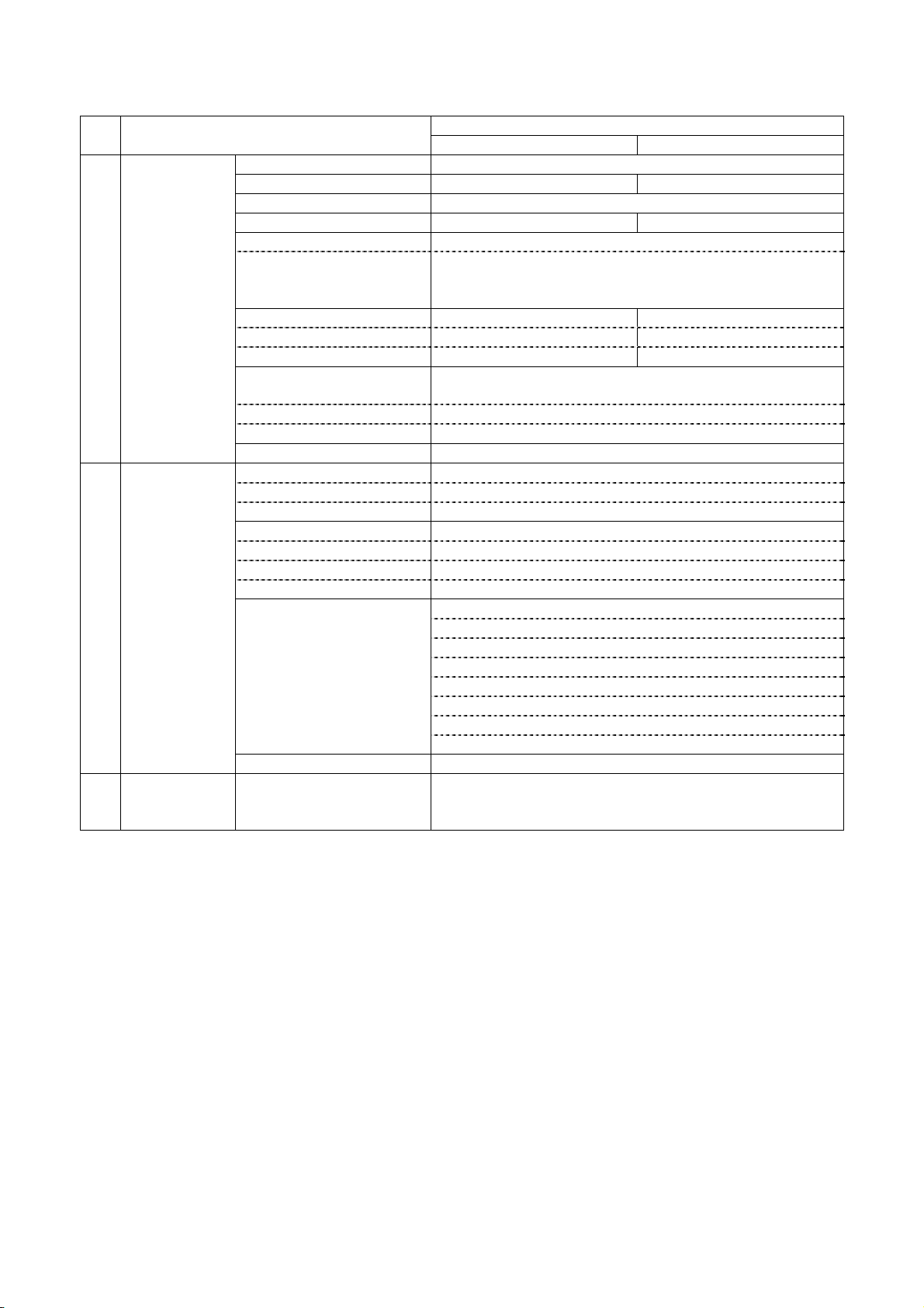
2. Specifications
2.1 Basic specifications
No. Items
NP-266 NP-366
Specifications
1 Print specs. 1. Print method Line thermal dot
2. Total dots / line 432 dots 576 dots
3. Dot density 8 dots / mm(203dpi)
4. Print width 54 mm 72mm
5. Print speed (Max.) Max. 220 mm / sec
Condition Head temp. more than 35 ℃/ ASCII full print
Except for communication time
※Max. 150 mm/sec for A type
6. Print digits
Font A (12×24) 36 digits 48 digits
Font B (9×17) 48 digits 64 digits
7.Space between Adjustable by the command
characters ※Default value
Font A (12 x 24) 0 mm
Font B (9 x 17) 0 mm
8. Line feed pitch 0.125 mm
2 Character 1. Character size
specs. Font A (12×24) 1.50×3.00 mm
Font B (9×17) 1.13×2.13 mm
2. Character types
ASCII 224
Block graphics 80 x 2
International 32
3.
Character modification
Double width
Vertical double
Quadruple
Bold
Double strike
Inverted
90°clockwise rotation
Underline
4. Line spacing (Default) 4.25 mm (1/6 inch)
3 Print mode ANK mode
Bit image mode
Barcode mode
D-F0382 NP-266/366 Product specifications Ver.1.10
3
Page 8

No. Items
NP-266 NP-366
Specifications
4 Barcode 1. 1-D symbology UPC-A
specs UPC-E
EAN-13 (JAN-13)
EAN-8 (JAN-8)
CODE39
ITF
CODABAR (NW-7)
CODE128
2. 2-D symology QR code
5 Interface 1. Serial RS232C (R type)
2. USB V.2.0 FULL SPEED (U type)
6 Auto-cutter 1. Cut method Guillotine type
2. Applicable paper Thermal 60 - 80 (micro)
3. Cut cycle 30 cuts / minute
4. Cut mode Full cut
Partial cut (a 2mm tab left at the center)
( Factory option setting before ship)
5. Life time 500,000 cuts
7 Presenter 1. Applicable paper - Thermal paper (65μm)
(NP-366*A*) 2. Length to feed - 70-250 mm
3. Feed speed - Max. 690 mm/sec.
4. Eject operation - Cramp
Total eject
Retraction
5. Life - 100,000 papers
8 Paper specs. 1. Paper width 58.0
mm 80.0
+0-1
+0-1
mm
2. Max. diameter Ø80 mm
3. Core diameter Inner Ø12mm
Outer Ø18mm
4. Papers recommended TF50KS-E2D (Nihon Seishi)
PD160R-N (Shin Oji Seishi)
HP220AB1 (Mitsubishi Seishi)
9 Receiving Approx. 10K bytes
buffer
10 Operation ALMLED OUT
SW Line feed SW input
11 Near empty ※1 Approx. Ø24±1mm
12 Environment 1. Operation Temp. 5~45℃, Humidity 35~85%RH No condensation
2. Storage Temp. -10~60℃, Humidity 35~90%RH
Except paper discoloration
3. Normal environment General office use
13 External spec 1. Dimension 103.5(W) x 106.7(D) x 127.2(W) x 106.7(D) x
161.3(H) mm 161.3(H) mm
NP-366*A*
127.2(W) x 154.0(D) x
161.3(H)
2. Weight Approx. 1.1 kg Approx. 1.3 kg
(without paper) (without paper)
NP-366*A *
Approx. 1.6 kg
(without paper)
※1: Paper should not be loosen for proper detection.
D-F0382 NP-266/366 Product specifications Ver.1.10
4
Page 9
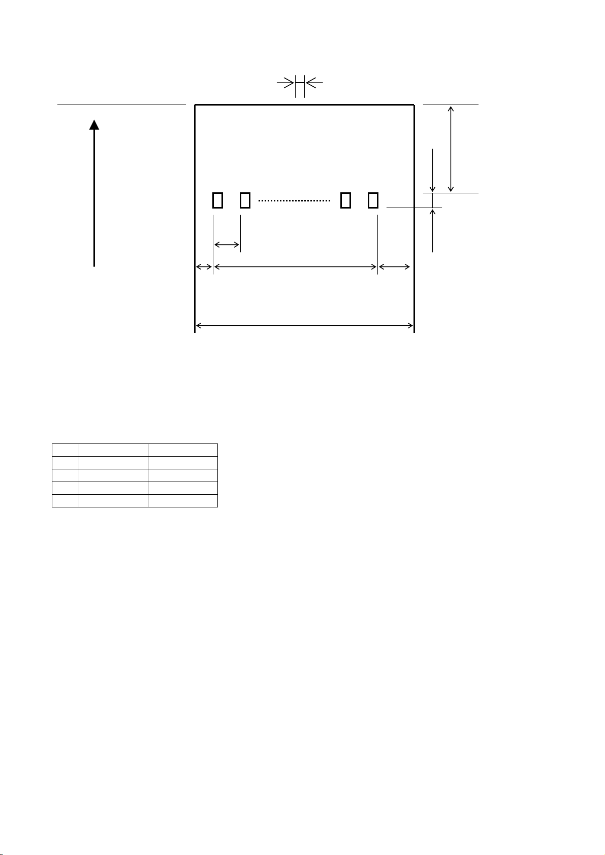
2.2 Printing area and cut position
Partial cut remaining tab: approx. 2 mm (P type only)
Cut Position
Cutter to Head
Approx.13±1.0mm
1dot 2dots D dots (Note1)
Feed direction
0.125mm
0.125mm
B ±0.2mm
(Note1)
A ±1.0mm A ±1.0mm Approx. 6 mm feed will
take place by the
C mm firmware, so the margin
0
-1
will be 19±1mm.
Note2: Please take care not to take the paper very hard after the partial cut, which cause heavy load on
platen and might cause the poor print quality on the head part of next line. To avoid such problem,
please take care by feeding approx. 1 mm at the beginning of print or by take the paper to the direction
to left or right.
Note3: The cut mode (full cut or partial cut) is set by the factory. No change of cut mode is done by the
command setting.
NP-266 NP-366
A 2 4
B 54 72
C 58 80
D 432 576
D-F0382 NP-266/366 Product specifications Ver.1.10
5
Page 10

2.3 Power supply specifications
1) Power supply input connector
Optional AC adapter will be used for this printer(Power to be supplied from outside)
Connector on printer side :TCS7960-532010 Hosiden or equivalent
Connector on Adapter side :TCP8927-631100 Hosiden or equivalent
2) Electrical condition
Operating Voltage : DC24V±5% (Type II)
: DC24V±5%, DC5V±5% (Type I)
Current Consumption
Standby : Average approx. 0.1 A
Printing :
Power supply Printing average of 25% Printing average of 100 %
NP-266 I 24V Max. approx. 2.10 A Max. approx. 8.33 A
5V Max. approx. 0.16 A Max. approx. 0.17 A
NP-266 II 24V Max. approx. 2.10 A Max. approx. 7.33 A
NP-366 I 24V Max. approx. 2.90 A Max. approx. 11.33 A
5V Max. approx. 0.16 A Max. approx. 0.17 A
NP-366II 24V Max. approx. 2.90 A Max. approx. 10.67 A
NP-366 IA 24V Max. approx. 2.90 A Max. approx. 11.38 A
5V Max. approx. 0.16 A Max. approx. 0.17 A
NP-366IIA 24V Max. approx. 2.90 A Max. approx. 10.72 A
* Paper Feed only : Average approx. 0.30 A
3) Standard Adapter specifications(Option)
Model : POWER SUPPLY PS3 (UP0601S-24P)
Maker : UMEC
Input Power Voltage : AC100V~AC240V
Output Power Voltage : DC24V±5% 2.5A max
Note:
Printing average of 25% is available for the optional AC Adapter PS3 (UP0601S-24P) for NP-266 and
20% for the NP-366. Please use a higher capacity AC adaptor for more than such printing or for the
other power supply prepared by your side.
No Function
1 +24V
2 GND
3 N.C
Shell FG
Connector drawing
1
3
2
D-F0382 NP-266/366 Product specifications Ver.1.10
6
Page 11

2.4 Reliability
1) Head life
Pulse : More than 100 million pulses (Applied 25℃ of rated energy)
Wear distance : More than 100 km
* Normal temp. Normal humidity with recommended paper
2) Cutter life : 0.5million cut
3) Presenter life : 100, 000 paper feed
4) Operation environment : Temperature 5℃ – 45℃ non-condensation
Humidity 35%-85%RH
5) Storage environment : Temperature -10℃ - 60℃ (paper not included)
Humidity: 35% - 90%RH
6) Safety regulation
CE marking (NP-266 only)
C-UL UL60950 (NP-266 only)
D-F0382 NP-266/366 Product specifications Ver.1.10
7
Page 12
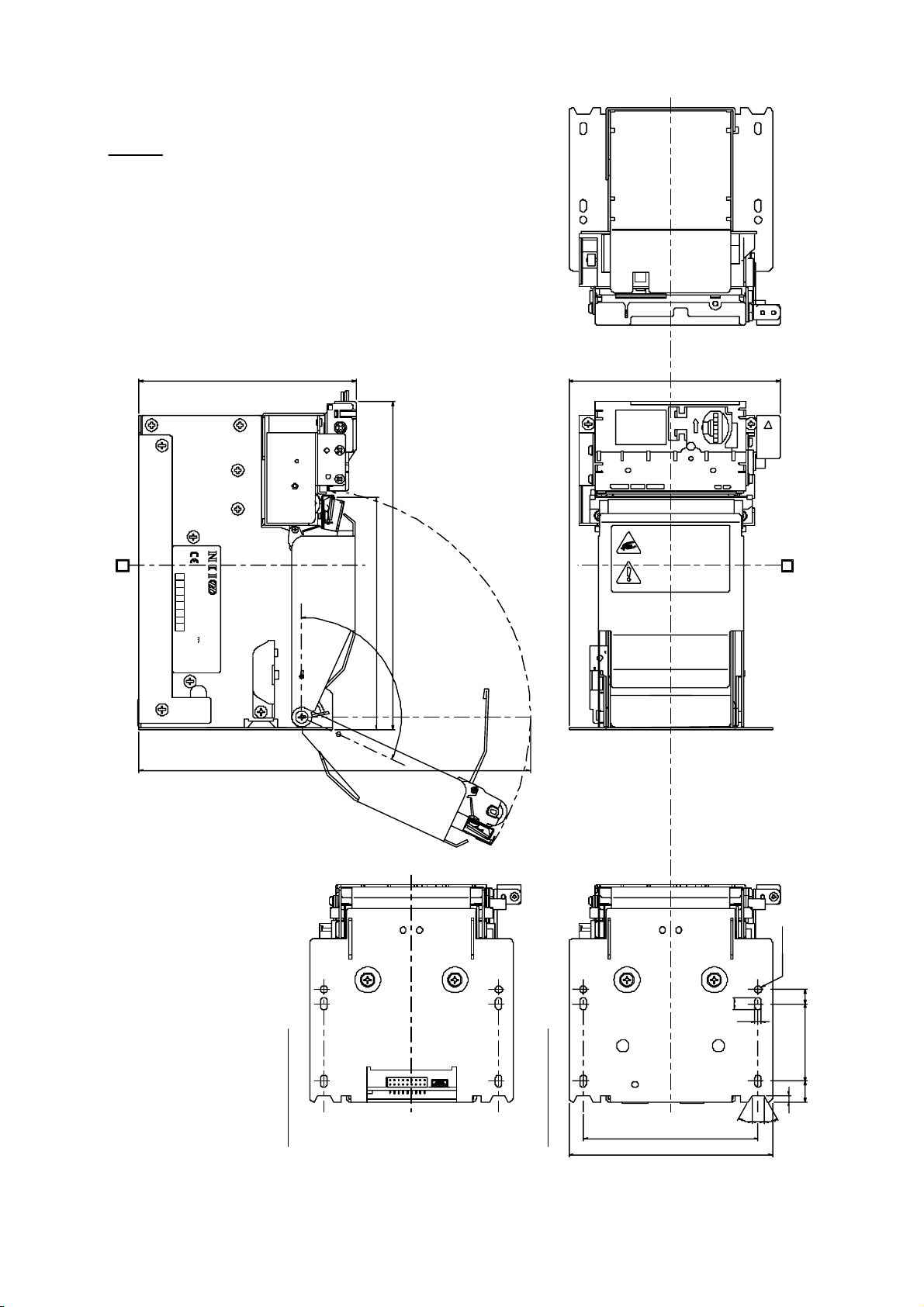
2.5 Dimensions
1) NP-266
Notes
1. More than 195 mm space needed for opening platen.
2. Either full cut or partial cut should be selected
3. Max. roll paper diameter Is 80 mm.
4. This drawing is "NP-266ⅡFU".
Nichipri Industrial Inc.
Revision
B
Hard Ware
12345678
Serial No.
Model
Rating 24V 1.9A
4B0001
NP-266ⅡFU
Made in Japan
106.7
(195)
NP-266Ⅰ**
103.5
押
161.3
paper exit
114.5
115°
NP-266Ⅱ**
・手指をはさまないよう注意して下さい。
Watch your hand when cover is colsed.
・用紙交換時はカバーに注意して下さい。
Pay attention to your when replacing paper.
A
2-φ3.5
6
4ヶ所
3.2
387 10.2
D-F0382 NP-266/366 Product specifications Ver.1.10
15
3
6 30°30°
86
100
±0.2
8
Page 13
B
7 8
45
ON
1
A
FEED
ALM
POWER
NP-266Ⅱ*R NP-266Ⅰ**
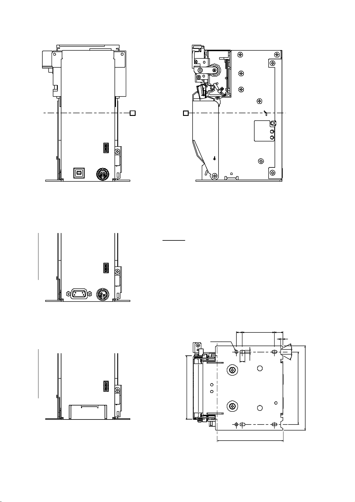
Notes
1. More than 195 mm space needed for opening platen.
2. Either full cut or partial cut should be selected
3. Max. roll paper diameter Is 80 mm.
7 8 23 6
45
36
ON
1
9
165
4. This drawing is "NP-266ⅡFU".
Recommended dimension for mounting plate
387 10.2
2-φ3.5
6
3.2
4ヶ所
7 8 2
45
23 6
ON
1
78 over
3
30°30°
6
±0. 2
86
100
D-F0382 NP-266/366 Product specifications Ver.1.10
Less than 78
9
Page 14
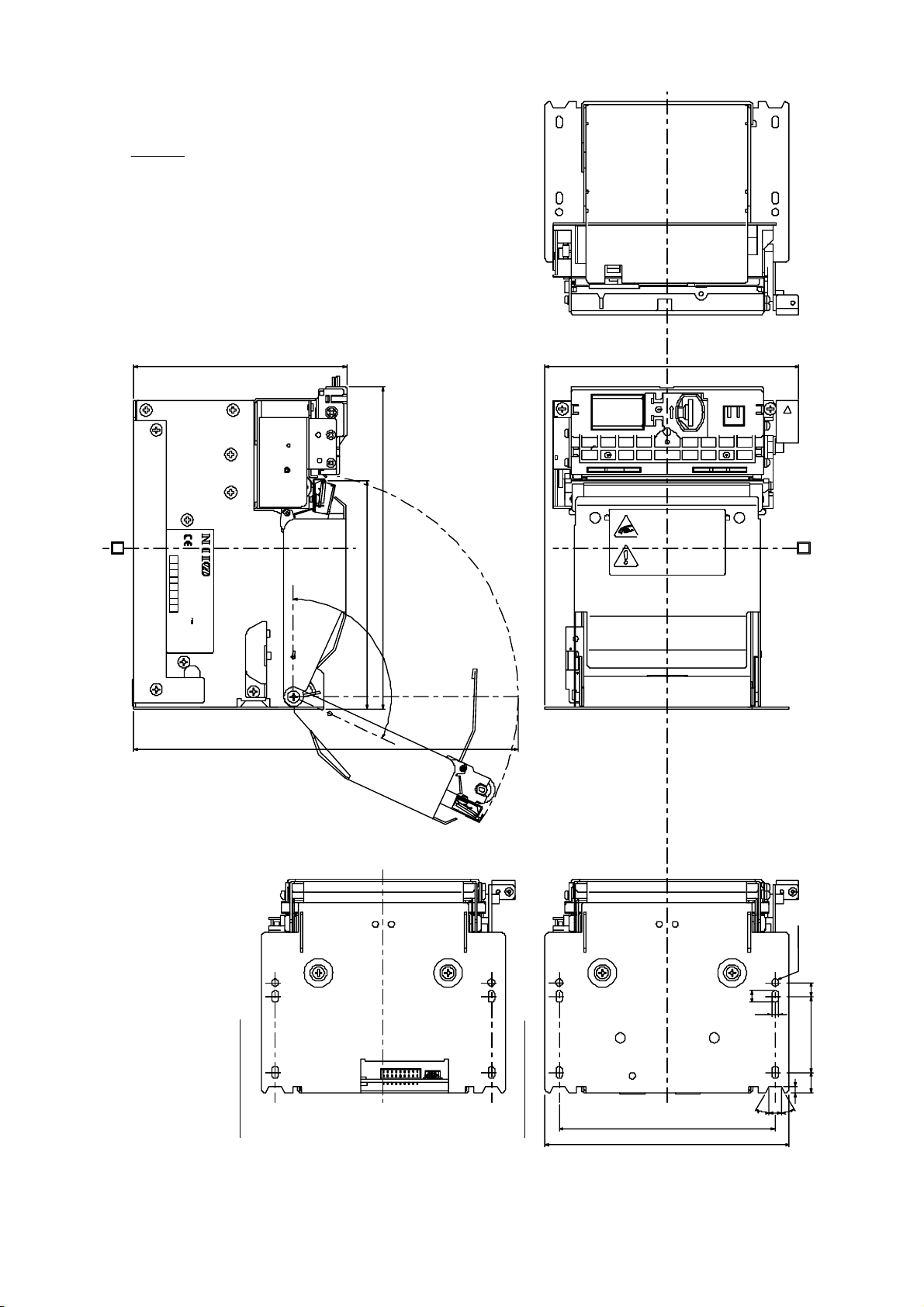
2) NP-366
Notes
1. More than 195 mm space needed for opening platen.
2. Either full cut or partial cut should be selected
3. Max. roll paper diameter Is 80 mm.
4. This drawing is "NP-366ⅡFU".
106.7
Nichipri Industrial Inc.
Revision
B
Hard Ware
12345678
Serial No.
Model
Rating 24V 2.7A
NP-366ⅡFU
4B0001
Made in Japan
161.3
paper exit
114.5
115°
127.2
・手指をはさまないよう注意して下さい。
Watch your hand when cover is cols ed.
・用紙交換時はカバーに注意して下さい。
Pay attention to your when replac ing paper.
押
A
(195)
NP-366Ⅰ**
D-F0382 NP-266/366 Product specifications Ver.1.10
15
10
NP-366Ⅱ**
108.2
122.2
±0.2
2-φ3.5
6
4ヶ所
3.2
387 10.2
3
30°
6
30°
Page 15

NP-366Ⅱ*R NP-366Ⅰ**
B
ON
1457823 6
A
FEED
ALM
POWER
Notes
1. More than 195 mm space needed for opening platen.
2. Either full cut or partial cut should be selected
3. Max. roll paper diameter Is 80 mm.
4. This drawing is "NP-366ⅡFU".
23 6
ON
14578 23 6
6
195
Recommended dimension for mounting plate
387 10.2
2-φ3.5
6
3.2
4ヶ所
3
30°
6
30°
ON
14578
D-F0382 NP-266/366 Product specifications Ver.1.10
11
100 over
Less than 78
±0.2
108.2
122.2
Page 16

2) NP-366ⅡAU
Revision
Hard Ware
12345678
Made in Japan
154.0
127.2
押
Nichipri Industrial Inc.
Serial No.
Model
Rating 24V 2.7A
4B0001
NP-366ⅡAU
115°
(220)
(108)
161.3
・手指をはさまないよう注意して下さい
paper exit
119.5
Watch your hand when cover is cl osed
・用紙交換時はカバーに注意して下さい
Pay attention to your when repla cing paper
Notes
1. More than 220 mm space needed for opening platen.
2. Max. roll paper diameter Is 80 mm.
3. This drawing is "NP-366ⅡAU".
D-F0382 NP-266/366 Product specifications Ver.1.10
12
108.2
122.2
2-φ3.5
6
4ヶ所
3.2
10.2387
6
±0. 2
30°30°
Page 17

3. Interface specifications
3.1 Serial interface (RS-232C)
1) Synchronization : Asynchronous
2) Transmission speed:19200, 38400bps (user selectable)
3) A word consists of
Start bit : 1bit
Data bit : 8 bit
Stop bit : more than 1 bit
4) Signal polarity
RS-232C
Mark = Logic “1” (-3V -- -12V)
Space = Logic “0” (+3V -- +12V)
5) Receive data (RD signal)
RS-232C
Mark = 1
Space = 0
6) Reception control (CTS signal)
RS-232C
Mark = Impossible to transmit data
Space = Possible to transmit data
7) Reception control (RTS signal)
Space = Possible to transmit data
Mark = Impossible to transmit data
3.2 USB interface (USB)
1) Version: V2.0 FULL SPEED (12Mbps)
2) Port: Upstream port (B jack or Mini-B)
3) Power Supply: Self Powered
D-F0382 NP-266/366 Product specifications Ver.1.10
13
Page 18

3.3 Connector signal details
1) Data signal input connector (Serial Type II)
Printer side : 17LE23090-027(D4CK) (DDK) or equivalent
Host side : 17JE13090-02(DDK) or equivalent
Pin No. Signal Input/Output Function Remark
1 N.C -
2 TXD Output Serial transmit data
3 RXD Input Serial receving data
4 N.C -
5 GND - Singnal ground
6 - -
7 CTS Input Transmit permission signal
8 RTS Output Transmit request signal
9 N.C
2) Data signal input connector (Serial Type I)
Data signal and power input
Connecter on printer: DF11-18DP-2DS (52) Hirose
Proper connecter : DF11-18DS-2C Hirose
Pin No. Signal name Input/Output Function Remarks
1 /RESET Input RESET Input (-)
※1
2 RTS Output Printer busy
3 CTS Input Host busy
4 - - N.C.
5 RXD Input Receives data
6 TXD Output Transmitted data
7 GND - Common GND
8 GND - Common GND
9 GND - Common GND
10 GND - Common GND
11 GND - Common GND
12 GND - Common GND
13 +5V Input Circuit power Vcc
14 +5V Input Circuit power Vcc
15 +24V Input Power supply VM for head, cuter, motor
16 +24V Input Power supply VM for head, cuter, motor
17 +24V Input Power supply VM for head, cuter, motor
18 +24V Input Power supply VM for head, cuter, motor
※2
※2
※2
※2
※2
※2
※2
※2
※2
※2
※2
※2
※1. It is reset by “L” pulse input at 50msec (typical). The level is below 0.7V.
/RESET signal input is effective only on Serial Type I.
※2. All pin no.7 -18 to be connected. Please connect thick and short, as large current may flow.
Please take necessary measure to stabilize the power supply by connecting a electrolytic
condenser (approx. 2200μ) or so. Withstand voltage over 35V must be applied.
※3. Pin no.7-18 are the same when USB for type I.
D-F0382 NP-266/366 Product specifications Ver.1.10
14
Page 19

3) Data Signal Input Connector (USB for type II)
Printer side connector: B jack DUSB-BRA42-T11(DDK) or equivalent
Host side Connector: B plug
Pin No. Signal Input / Output Function Remark
1 VBUS Input Power line Non twist power line
2 D- Input and output Data line Twist pair signal line
3 D+ Input and output Data line Twist pait signal line
4 GND - Power line Non twist power line
Shell Shield -
* Use USB cable which conforms to the standard (FULL SPEED)
* We do not support the operation by using a cable out of the standard.
4) CN9 Data Signal Input Connector (USB for type I)
Printer side connector: Mini-B 5P TCX0101-110100 Hosiden or equivalent
Host side Connector: Mini-B 5P equivalent
Pin No. Signal Input / Output Function Remark
1 VBUS Input Power line Non twist power line
2 D- Input and output Data line Twist pair signal line
3 D+ Input and output Data line Twist pait signal line
4 N.C -
5 GND - GND Non twist power line
Shell Shield - FG frame GND
* Use USB cable which conforms to the standard (FULL SPEED)
* We do not support the operation by using a cable out of the standard.
D-F0382 NP-266/366 Product specifications Ver.1.10
15
Page 20

4. Functions
4.1 Function setting
4.1.1 DIP switch DS1
Functions ON OFF
Factory setting
U type R type
DS1-1 Interface USB Serial ON OFF
DS1-2 Kanji code Shift JIS JIS OFF OFF
DS1-3 Near empty sensor Ineffective Effective OFF OFF
DS1-4 Print density select 125% 100% OFF OFF
DS1-5 Character set Overseas Domestic OFF OFF
DS1-6 Baud rate 38400bps 19200bps OFF OFF
DS1-7 Print speed select Max.150 mm/s Max. 220 mm/s OFF OFF
DS1-8 Partition drive 2 partition Automatic OFF OFF
※ Print speed is 150 mm/sec for A type, regardless of setting of DS1-7.
※ The above setting is subject to change for adding 9600 bps baud rate
4.1.2 Paper sensor
Paper end sensor equipped in the paper course of the printer mechanism. Applicable bit of
status will be ON and sotp printing when detected the paper end.
Print data will be ignored when detected the paper end during printing. Change of setting and
status command will work as normal. The sensor can not detect paper end of the roll with glue.
Please load the paper when detected the paper end.
D-F0382 NP-266/366 Product specifications Ver.1.10
16
Page 21
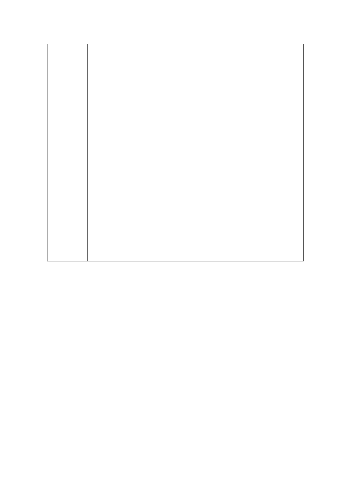
4.2 Processing error
1) Error detection details
Name Status Status
Comm. error
Paper near
empty
Rear cover
open
Paper end
Excessive
Head temp
Cutter error
Presenter
error
Presenter
cramp
232C Comm. error
Parity
Overrun
Flaming
Data “?” print
Remaining paper detect
near empty detection
Rear cover open
No paper
Over approx.80
Cutter error
Presenter error
Presenter cramp the paper
°C
-
0 bit 1
1 bit 1
2 bit 1
3 bit 1
4 bit 1
5 bit 1
6 bit 1
ALM
status
-
Blink-1
On
On
Blink-2
Blink-2
Blink-3
Blink-3
Adjust comm.condition
Load paper
Close the rear cover
Load paper
Return regular operation
At 60
After removing the error,
(Jam etc), turn on power
again or input /RESET
signal
After removing the error
(jam etc), turn on power
again or input /RESET
signal
Remove the paper
Removal
°C(approx.)
When the above errors are detected (except transmission error and paper empty end error), printer
stops all operation and turn on the error bit of the status.
Note: Blink-1: 0.5 sec on and 0.5 sec off
Blink-2: 2.5 sec on and 0.5 sec off
Blink-3: 0.2sec on and 0.2sec off x 3 times, 1.0 sec on, 0.2 sec off
2) Return to normal status from error statuses
Remove causes of error statuses and turn the power on again or input the /RESET signal
to return to normal. When this process is activated, at the time of power switch turned off,
the printer will be initialized, so that settings are required again.
If data remains in the buffer, attention should be paid
D-F0382 NP-266/366 Product specifications Ver.1.10
17
Page 22
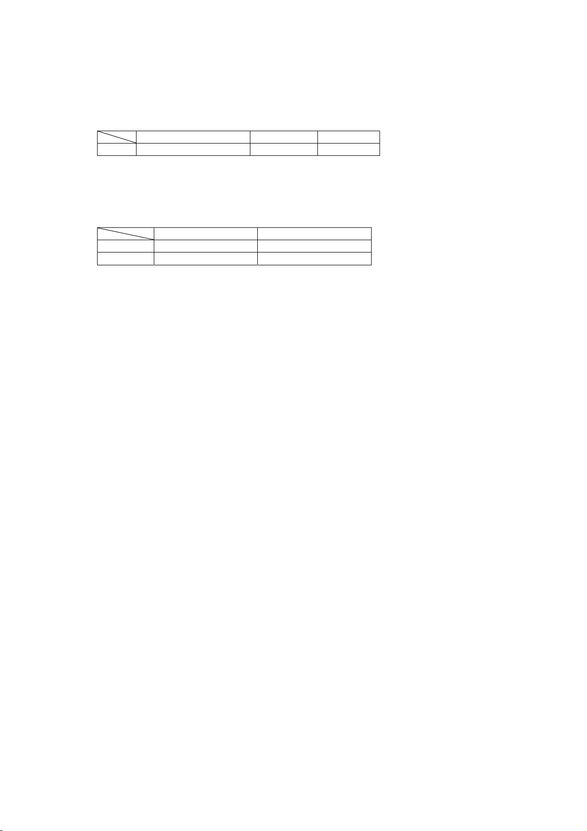
4.3 Partition drive
The 2 partition drive or “Automatic partition drive” can be selected by the DIP switch and
1partition drive can be selected by a command. It should be selected according to the power
supply capacity and print duty.
1) Fixed partition
Function ON OFF
DS1-8 Partition drive select 2 partitions Automatic
* 2 fixed partition and Automatic partition select may decrease print speed.
* 1 partition drive can be selected by a command.
2) Automatic partition drive
Select automatically 1 partition or 2 partitions by total dots / line.
1 partition 2 partitions
NP-266 Less than 248 dots Higher than 249 dots
NP-366 Less than 352 dots Higher than 353 dots
* Automatic partition drive will change the print speed according to print ratio. Print noise may
occur.
* The default status is set as selected. Partition setting can be selected by DIP switch or
command. Refer to the command description for the details.
* Automatic partition select may decrease print quality.
* Automatic partition select may decrease print speed.
4.4 Operation panel
1) FEED SW [Paper feed switch]
Switch to feed paper in the normal direction
Also, used in rewriting Flash Rom, and self-printing.
2) ALM (red) [alarm lamp]
Will turn on (or blink) when printer is on error status.
Will turn on/ blink/ turn off when rewriting Flash Rom
3) POWER (green) [power lamp]
Will turn on when power is supplied to printer
D-F0382 NP-266/366 Product specifications Ver.1.10
18
Page 23
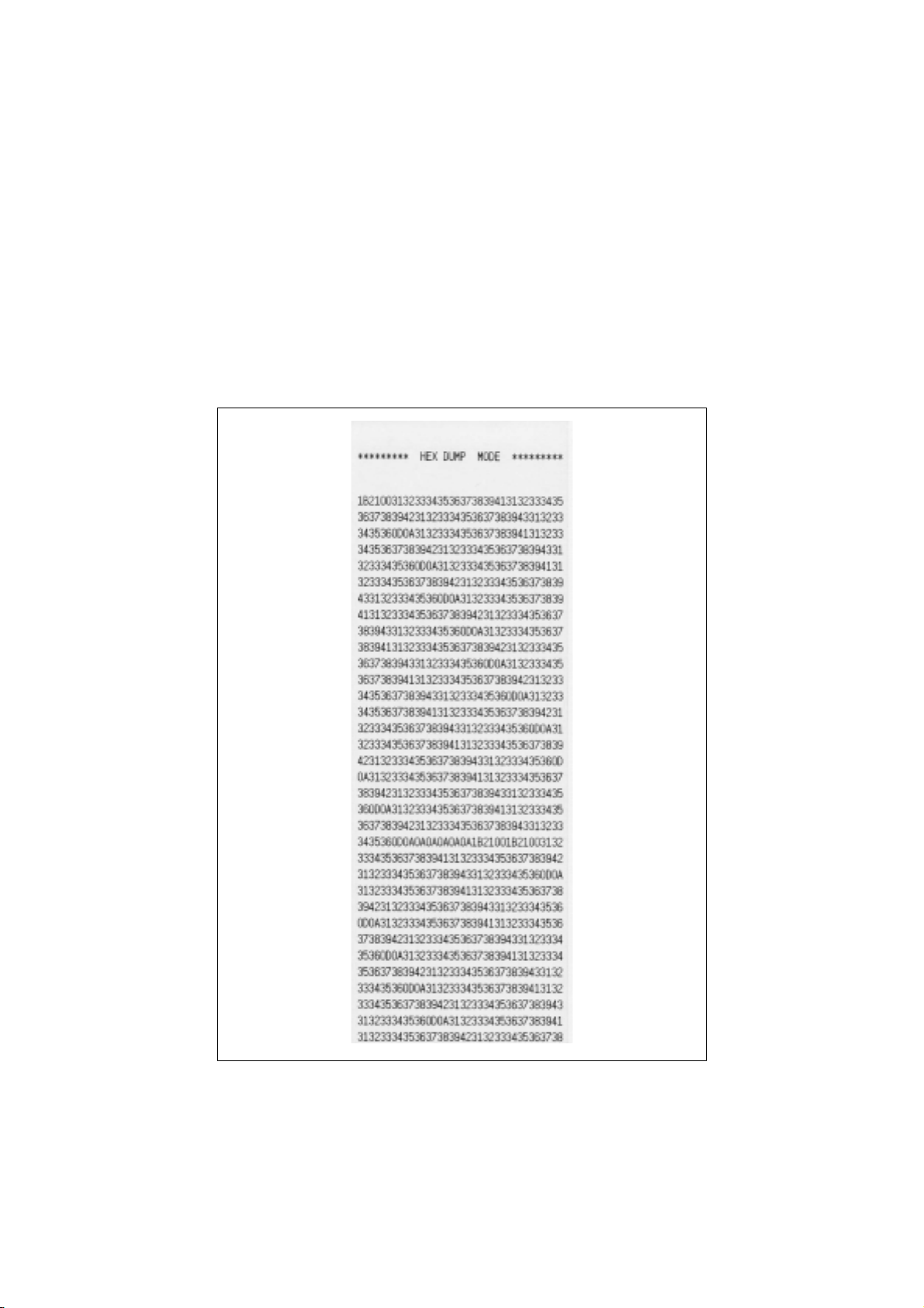
4.5 HEX dump print
1) HEX dump function
Data sent from host will be output in HEX, used for application debug and analysis of
distorted characters.
2) Start and end of HEX dump
Open the front cover when the nomal printer status, then close during pressing LF switch.
Keep pressing the LF button for 5 seconds, printer will be HEX dump mode. Then, HEX
dump will start. HEX dump will stop as you turn off power or input /RESET signal.
Printing Sample
D-F0382 NP-266/366 Product specifications Ver.1.10
19
Page 24

4.6 Self print
1) By performing self-diagnostic print following items are checked.
a) Proper function of control circuitry
b) Proper function of printer mechanism
c) Print quality
d) Control F/W version
e) DIP switch setting status
f) Correct function of paper out sensor
2) Start and end of self diagnostic print
Open the front cover. Close the cover while pressing the FEED switch and release the FEED
switch within 5 seconds. Self diafnostic print will take place.
The self diagnostic print automatically ends when a preset number of characters are finished
printing. While printing, the printer is in Off-line mode. Without paper is loaded, no print occurs.
4.7 Buffer full print
If there remains data in the buffer after one line of data is received, printer automatically prints
preceding data. The volume of buffer full data varies depending on ASCII characters (Font A, B)
or bit images.(Line mode)
4.8 Presenter drive
Presenter NPT-305 can be drived.
※A type only
※Print speed is max. 150 mm/sec for A type.
D-F0382 NP-266/366 Product specifications Ver.1.10
20
Page 25
5. Software specifications
5.1 Printer driver
Please apply the driver stated below for using under Windows environment. Please refer to the
User’s Manual for detailed information.
1) Windows 95/98: NII printer driver Windows 95/98, Version 1.00
2) Windows NT4.0: NII printer driver Windows NT4.0, Version 1.00
3) Windows 2000 / XP: NII printer driver Windows 2000, Version 1.00
4) Windows 2000/ XP: NII printer drive Windows 2000 USB, Version 1.00
5.2 Line mode command table
Command Functions Pages
1 HT Horizontal tab 23
2 LF Print and paper feed 23
3 FF Page feed 23
4 CR Carriage return 23
5 DLE CAN Reset software 23
6 ESC SP n Character right space set 23
7 ESC ! n Print mode overall set 24
8 ESC $ n1 n2 absolute position set 24
9 ESC % n Download character set/reset 24
10 ESC & s n m a Dn Download character definition 25
11 ESC * m n1 n2 Dn Bit image mode set 28
12 ESC – n Underline set/reset 29
13 ESC 2 1/6 inches line feed set 29
14 ESC 3 n Smallest line feed pitch set 29
15 ESC = n Data input control 29
16 ESC @ Initialize printer 30
17 ESC C n Page length set for n lines 30
18 ESC D n1 n2 --- NUL Set horizontal tab position 30
19 ESC E n Bold print set/reset 30
20 ESC G n Double strike print set/reset 31
21 ESC J n Print and smallest pitch line feed 31
22 ESC L Page mode select 31
23 ESC R n Select international character 31
24 ESC V n Character 90°clockwise rotation set/reset 32
25
ESC \ n1 n2
relative position set 32
26 ESC a n position alignment 32
27 ESC c 5 n FEED switch effective/not effective 32
28 ESC d n Print and n line feed 32
29 ESC i Cut 33
30 ESC t n Select Character code table 33
31 ESC q S E M QR code print 34
32 ESC v Send Printer Status 36
33 ESC { n Inverted character set/reset 36
34 GS % n Partition drive selection 37
35 GS d Dn Firmware download 37
36 GS f n Select of HRI character style 37
37 GS h n Select height of barcode 37
38 GS k n Dn NUL Print barcode 38
39 GS w n Select width of barcode 38
40 GS v NUL Automatic transmission of printer status 38
41 GS H n Select HRI character print position 39
D-F0382 NP-266/366 Product specifications Ver.1.10
21
Page 26

Control codes Functions Pages
42 GS P n Print NV bit image 39
43 GS T n Register NV bit image 39
44 GS ~ n Set Print Density 39
45 ESC b n1 n2 n3 Raster bit image 40
46 GS * n1 n2 Dn Definition of download bit image 41
47 GS / m Print download bit image 41
48 ESC r 0 Presenter cramp compulsory eject 42
49 ESC r 1 n Presenter retraction time setting 42
D-F0382 NP-266/366 Product specifications Ver.1.10
22
Page 27

5.3 Line mode command details
1) Horizontal tab : << HT >>
Code : [09] h
Shift the print position to the next horizontal tab position
* Horizontal tab position is set by [horizontal tab set] command.
* The default status of horizontal tab position is set at every 8th character (9th digit,
17th digit, 25th digit and 33rd digit) in font A.
※41st digit for NP-366
* If the next tab position is not set, this command is ignored.
2) Line feed : << LF >>
Code : [0A] h
Prints data stored in the print line buffer and executes line feed according to data
of feed pitch.
3) Page feed : << FF >>
This command is effective only in Windows mode.
Code : [0C] h
* Prints data in the print line buffer and executes page feed to the head of next page
according to the page length in the setting.
* Default setting for the page length is [42] h ( 66 lines) .
4) Carriage return: << CR >>
Code : [0D] h
This command is ignored.
5) Software reset : << DLE CAN >>
Code : [10] h + [18] h
Description :Firmware is treated in the same manner as power is set on to start again.
* The command is stored in the internal receive input buffer and activated sequentially.
* After cutter action is completed, but during operation process, it returns to software
operation.
* If there is any data, not yet transferred, in the transfer buffer, it goes to software reset action
after all data are transferred.
6) Setting right space of a character: << ESC SP n >>
Code : [1B] h + [20] h + n * [00≤n≤20] h
Sets the right space of a character by unit of dot (1/203 of an inch). In the case of
double width mode, the space will be doubled. The default value of “n” is [00] h.
D-F0382 NP-266/366 Product specifications Ver.1.10
23
Page 28
7) Overall print mode setting: << ESC ! n >>
Code : [1B] h + [21] h + n * [00≤n≤FF] h
Sets print mode. “n” has following meanings
Bit Function
Values
0 1
0 Character font Font A Font B
1 Undefined - 2 Undefined - 3 Bold Reset Set
4 Double height Reset Set
5 Double width Reset Set
6 Undefined - 7 Underline Reset Set
* If double height and double width are set at the same time quadruple character will be formed.
* All of the printed characters will be underlined except for the 90° clockwise rotated characters
and spaces created by horizontal tab.
* Underline width is determined by the value set in [Underline set/reset] section.
The default value is “1”.
* Different sizes of character mixed such as double width and normal size can be printed.
* The default value of “n” is [00] h.
8) Absolute position set :<< ESC $ n1 n2 >>
Code : [1B] h + [24] h + n1 + n2 * [00≤n1≤FF] h
* [00≤n2≤02] h
Print start position is assigned by dots in 1/203rd of inch from the beginning of line.
* Divide the value of dot by 256, place quotient to n2, and remainder to n1.
* The print start position is n1 + n2 x 256 from top of the line.
* Setting which exceeds end of line is ignored.
9) Down load characters set/reset : << ESC % n >>
Code : [1B] h + [25] h + n * [00≤n≤FF]h
Setting or resetting the characters to be downloaded.
.
* Only LSB (b0) is valid for “n” value. LSB (b0) has the following meanings.
b0 Function
0 Resets download chraracter
1 Sets download chraracter
Default value is “n” = [00] h
D-F0382 NP-266/366 Product specifications Ver.1.10
24
Page 29

10) Definition of download character :<< ESC & s n m a Dn >>
Code : [1B] h + [26] h + s + n + m + a + Dn
* [s = 03] h
* [20≤n≤7E] h
* [20≤m≤7E] h
* Font A [01≤a≤0C] h
* Font B [01≤a≤09] h
Definition of download character( such as alpha numeric characters).
* “s” indicates a number of bytes in a vertical direction and “a” is a number of dots in
horizontal direction.
* “n” indicates the start character code, and “m” means the end character code. If only 1
character should be defined, then n = m.
* Definable characters are from <20>h to <7E>h in ASCII code (95 characters).
* “Dn” indicates the data to be defined. It indicates the “a” dots pattern from the left.
Remaining area on the right of a character is filled with spaces.
* Once a download character is defined, it remains valid until the download character is
redefined.
*Even though OFF/ON of power supply, Initialization of Printer and Software reset are
executed, Defined content is not cleared.
D-F0382 NP-266/366 Product specifications Ver.1.10
25
Page 30
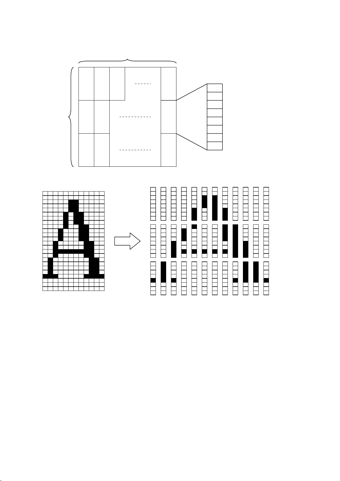
< Reference >
In the case of Font A
P1
12dots
P4
P7 P34
MSB
24dots
P2
P3
P5
P6
P35
P36
LSB
P1=〔00〕h,P4=〔00〕h,P7=〔00〕h,P10=〔00〕h,…
P2=〔00〕h,P5=〔00〕h,P8=〔0F〕h,P11=〔72〕h,…
P3=〔08〕h,P6=〔F8〕h,P9=〔08〕h,P12=〔00〕h,…
D-F0382 NP-266/366 Product specifications Ver.1.10
26
Page 31
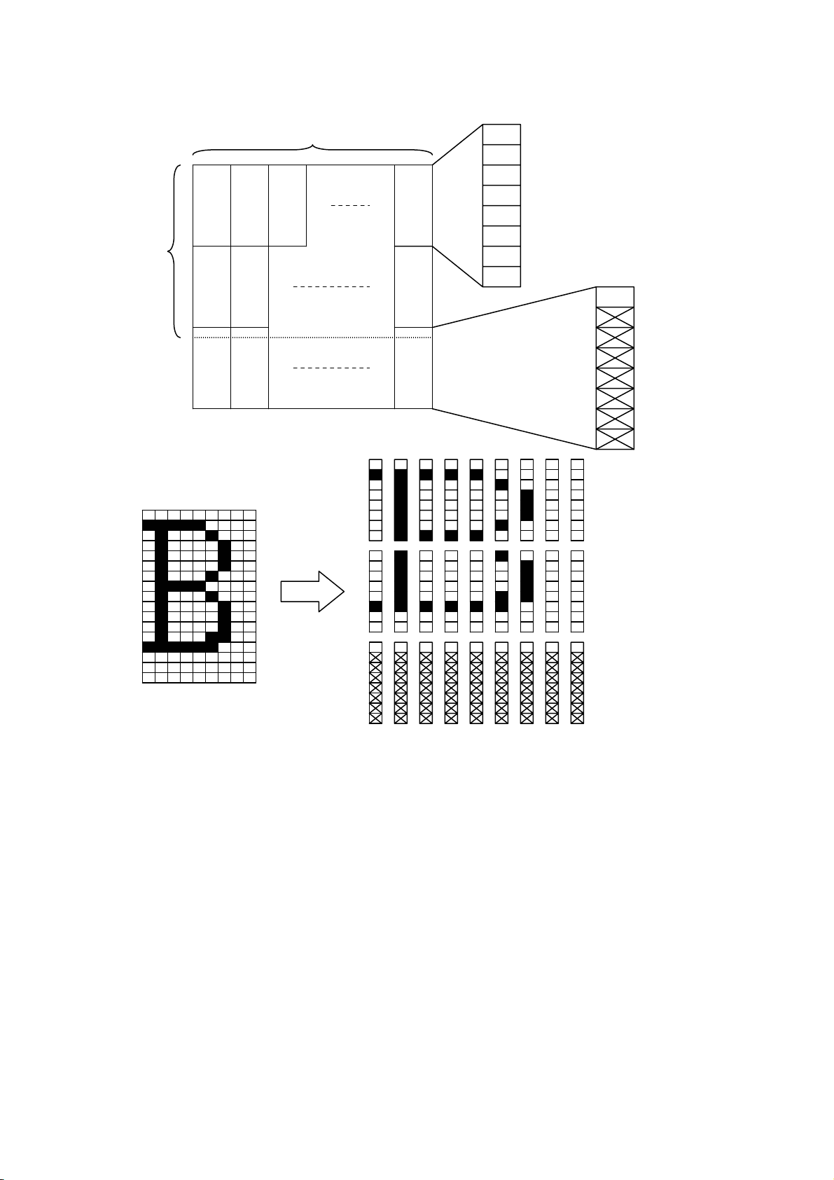
< Reference >
In the case of Font B
9dots
MSB
17dots
P4
P5
P7
P25
P26
LSB
MSB
P1
P2
P27P6 P3
LSB
P1=〔40〕h,P4=〔7F〕h,P7=〔41〕h,P10=〔41〕h,…
P2=〔04〕h,P5=〔FC〕h,P8=〔04〕h,P11=〔04〕h,…
P3=〔00〕h,P6=〔00〕h,P9=〔00〕h,P12=〔00〕h,…
D-F0382 NP-266/366 Product specifications Ver.1.10
27
Page 32
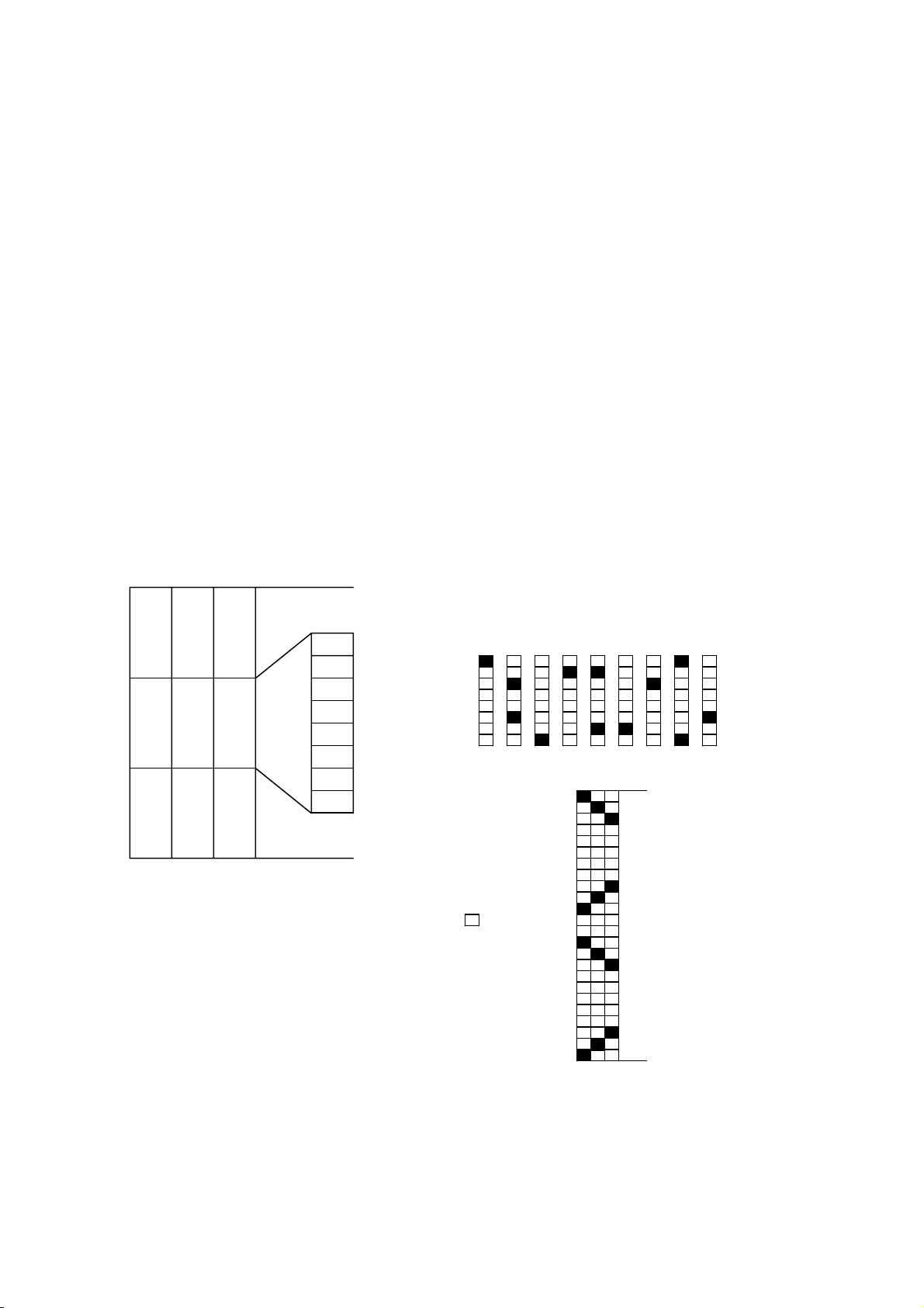
11) Bit image mode set: << ESC * m n1 n2 Dn >>
Code: [1B] h + [2A] h + m + n1 + n2 + Dn * [m = 23] h fixed
* [00≤n1+ (100hxn2)≤1b0] h NP-266
* [00≤n1+ (100hxn2)≤240] h NP-366
Data is printed in 24 dot bit image of resolution of 203 x 203DPI.
z Print total dots divided by 256, quotient is n2 and remainder is n1.
z Total dots in bit image mode are n1 + (256 x n2).
z If the bit image input data exceeds 1 dot/line position, the exceeded data will be
disregarded and it is not automatically printed in the next line.
z Bit image data (Dn) interprets bit 1 as print and bit 0 as not print.
z The total dots to be printed in the bit image must be the same with quantity of bit image
data that corresponds to the dots. If quantity of bit image data is less than the total dots,
the same amount of following data, same as the balance, is treated as bit image data. If it
is more than the total dots, the same exceeding volume of bit image data will be treated
as normal data.
z When bit image is continuously printed, print by lines (3mm) and stop is repeated for such
reason as communication speed and others, the print density may not be consistent. Use
NV bit image to solve the problem.
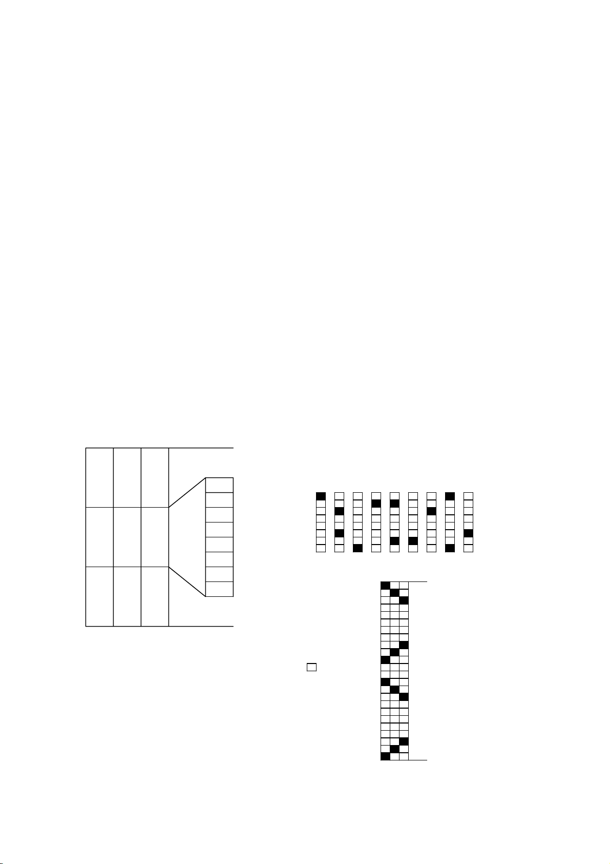
< Relationship between bit image data and printed dots >
24 dots bit image
D1
D4 D7 MSB
D1 D2 D3 D7 D8 D9
D4 D5 D6
D2 D5
D8
D3 D6
D9
LSB
Print Data
=1dot
D-F0382 NP-266/366 Product specifications Ver.1.10
28
Page 33
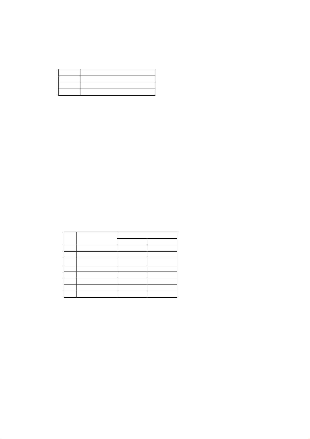
12) Underline set/reset : << ESC - n >>
Code : [1B] h + [2D] h + n * [00≤n≤02] h
Sets and resets the underline
* Underline is effective for all characters except for the area skipped by horizontal tab.
* Also Underline is not effective for 90°clockwise rotated character.
* Underline is verified with n value as shown bellow.
n(hex) Type of underlines
00 Reset underline
01 Set one dot underline
02 Set two dot underline
* Default value is “n” = [00] h
13) 1/6th of an inch line feed pitch : << ESC 2 >>
Code : [1B] h + [32] h
Sets one line feed to 1/6th of an inch.
14) Sets smallest pitch line feed : << ESC 3 n >>
Code : [1B] h + [33] h + n * [00≤n≤FF] h
Sets a line feed pitch to n/203rd of an inch.
*The height of character for a line (24/203 inch for normal character print) is sent by line
feed. If the value of “n” is set below the height of character(24/203 inch), the same space
as character height (24/203 inch) will be spaced by line feed.
* The default value of n is [22]h.
15) Data input control :<< ESC = n >>
Code : [1B] h + [3D] h + n * [00≤n≤FF] h
Description: Selects valid device where data input is possible through host computer.
* Each bit of “n” has the following meaning.
Bit Function
Values
0 1
0 Printer Invalid Valid
1 Not defined
2 Not defined
3 Not defined
4 Not defined
5 Not defined
6 Not defined
7 Not defined
* If printer is not in “no selection” status, printer will discard all received data until it is in
the selection status by this command.
* Even if printer is in no selection status, the status may become BUSY by printer
operation.
* The default value of “n” is [01] h.
D-F0382 NP-266/366 Product specifications Ver.1.10
29
Page 34

16) Printer initialization : << ESC @ >>
Code : [1B] h + [40] h
Clears the data stored in the print buffer and resets each setting to default values.
* It does not clear the data stored in the internal receive buffer.
* For each mode status in each setting function, refer to section 5.6 the
mode status (Line mode) for setting function, [ESC @].
* It is stored in the internal receive buffer and activated sequentially.
17) “n” line page length setting: << ESC C n >>
Code : [1B] h + [43] h +n * [01≤n≤FF] h
Sets a page length for “n” lines with current line feed pitch.
* Position is set to the head of page
* Line pitch change after setting will not change page length.
* Default value for “n” is [42] h for 66 lines.
* If printer is initialized, the head of page is also initialized.
18) Horizontal tab position set : << ESC D n1 n2 --- NUL >>
Code : [1B] h + [44] h + n1 + n2 + --- + [00] h *[00≤n≤FF] h
Sets the horizontal tab position
1. “n” indicates the digits number from the left to horizontal tab position . In this case, n =
tab position - 1.
2. Tab position is set at the location of character width x n from the beginning of a
line. The character width in this case includes character right space. When double
width function is set, then the width becomes double of ordinary character.
3. Maximum number of tab positions is 32. If setting exceeds 32, then
the exceeded values are neglected.
4. < ESC D NUL > clears all tab positions being set. After the tab is cleared,
horizontal tab will be ignored.
5. Default value is set at every 8 characters of font A (at 9
th, 17th, 25th and 33rd digit).
19) Bold print set/reset :<< ESC E n >>
Code : [1B] h + [45] h + n * [00≤ n ≤FF] h
Sets and resets the bold print
* “n” is only valid for LSB (b0)
LSB (b0) is defined as following.
b0 Values
0 Resets bold print
1 Sets the bold print
Valid for all characters
Bold print and double strike results in the same on this printer.
The default value of “n” is [00] h.
D-F0382 NP-266/366 Product specifications Ver.1.10
30
Page 35
20) Double strike set/reset :<< ESC G n >>
Code : [1B] h + [47] h + n * [00≤n≤FF] h
Sets and resets the double strike function
* “n” is only valid for (b0)
* Control by “n” is explained as following.
b0 Description
0 Resets double strike
1 Sets double strike
* Valid for all characters
* The effect of double strike and bold print are exactly the same on this printer.
* The default value of “n” is [00] h.
21) Print and smallest pitch line feed: << ESC J n >>
Code : [1B] h + [4A] h + n * [00≤n≤FF] h
Prints the data in the print line buffer and feeds the paper by n/203rd of an inch.
* The height of character for a line (24/203 inch for normal character print) is always sent
by line feed. If the value of height is set by “n” below the height of character, the same
space with character height is sent by line feed.
* Beginning of a line is a print start position.
* Line feed is not affected.
22) Page mode select: << ESC L >>
Code : [1B] h + [4C] h
Description : Switches between the line mode and page mode.
* The data in the line buffer is cleared.
* Clear the each setting and definition of the line mode.
* The line mode setting will be the same as the status on the printer initialization <ESC @>.
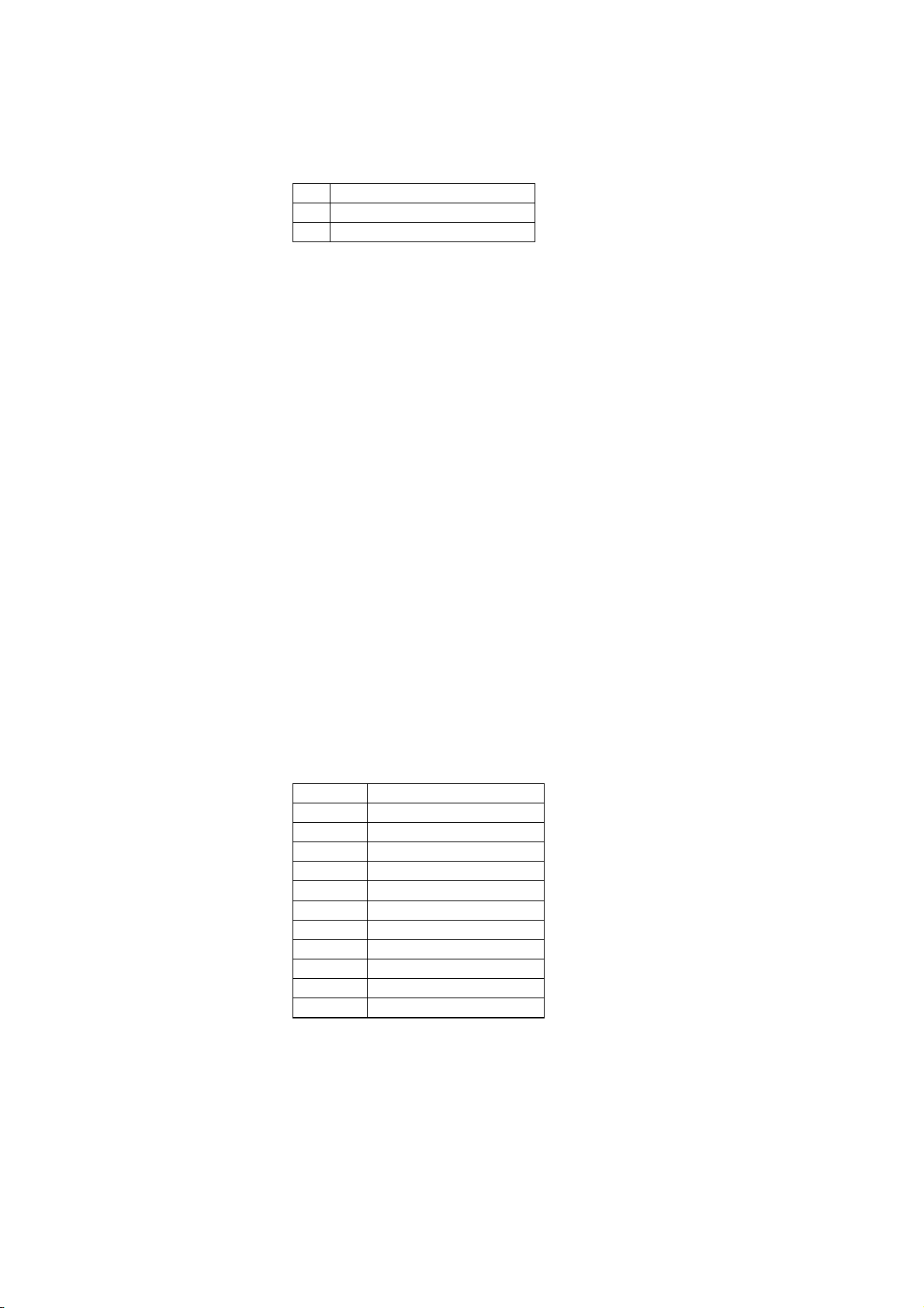
23) International character select :<< ESC R n >>
Code : [1B] h + [52] h + n * [00≤n≤0A] h
Description: Selects the international characters.
* The values of “n” have following meanings
n(Hex) Character sets
00 U.S.A.
01 France
02 Germany
03 England
04 Denmark 1
05 Sweden
06 Italy
07 Spain
08 Japan
09 Norway
0A Denmark 2
Default value of “n” is [08] h.
D-F0382 NP-266/366 Product specifications Ver.1.10
31
Page 36
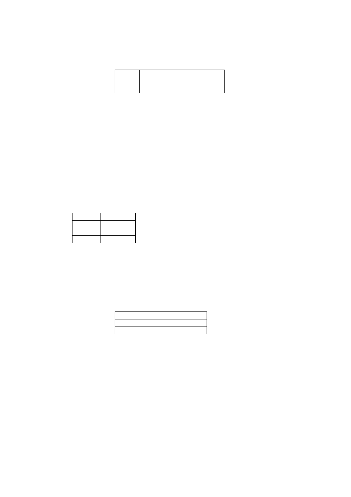
24) 90° clockwise rotated character set and reset :<< ESC V n >>
Code : [1B] h + [56] h + n * [00≤n≤01] h
Description: Sets and resets 90° clockwise rotated character.
* Underline cannot be assigned to the 90° clockwise rotated character.
* “n” has the following meaning.
n(hex) description
00
reset 90° rotated character
01
set 90° rotated character
* Default value for “n” is [00]h.
25) Relative position set :<< ESC ¥ n1 n2 >>
Code : [1B] h + [5C] h + n1 +n2 * [00≤n1≤FF] h
* [00≤n2≤02] h
Print start position is assigned by dots from current position in unit of 1/203rd of inch.
* Right direction is treated as plus and left as minus.
* To assign N dots in minus direction (left), it will be: N dots = 65536 - N
* Assigning beyond the end of a line is neglected
26) Print position alignment :<< ESC a n >>
Code : [1B] h + [61] h + n * [00≤n≤02] h
Description : Aligns all data to be printed on the assigned position in a line.
* “n” values are assigned to:
n (Hex) Position
00 Left
01 Center
02 Right
* This command is valid only when it is input at the head of a line.
* The default value of “n” is [00] h.
27) FEED switch enable/disable :<< ESC c 5 n >>
Code : [1B] h + [63] h + [35] h + n * [00≤n≤FF] h
Description: Changes the FEED switch valid or invalid.
* “n” is only valid for LSB (b0)
* “n” bit has following meanings
b0 Description
0 enable FEED switch
1 disable FEED switch
Default value of “n” is [00] h.
28) Print and “n” line feed :<< ESC d n >>
Code : [1B] h + [64] h + n * [00≤n≤FF] h
Description: Prints the data in the print buffer and feeds paper by “n” lines.
* Beginning of a line is the starting position of printing.
D-F0382 NP-266/366 Product specifications Ver.1.10
32
Page 37

29) Cut : << ESC i >>
Code : [1B] h + [69] h
Description: Execute paper cut
* Feeds paper by 3mm after paper cut to prevent from paper jam.
30) Character code table select : << ESC t n >>
Code : [1B] h + [74] h + n * [00≤n≤01] h
Description : Selects either Japan code table or overseas code table.
Explanation : “n” value has following meaning.
n(hex) character code table
00 Overseas character code table
01 Japan character code table
The default value of “n” is [DS1-5] for DIP SW.
D-F0382 NP-266/366 Product specifications Ver.1.10
33
Page 38
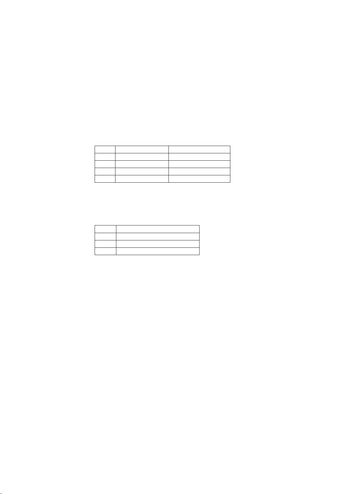
31) QR code print : << ESC q S E M >>
Code: [1B] h + [71] h + S + E + M + DATA [ <2C>h + M + DATA +….] + NUL
About parameter
1. S: module size
* Assign 1 module size of QR code by printer’s dot numbers.
* Selectable sizes are 1,2, 3, 4, 8 dots.
* If invalid size is assigned, the printer assigns it as 4 dots
Due to resolution level of the printing mechanism, data reading of module size 1,
2 and 3 cannot be guaranteed.
2. E: Correction level
* Selects error correction level to be used for restoring QR symbol.
* Following values can be assigned.
* If invalid value is assigned, the printer determines it to be L.
E Correction level Restore. capability
0 L 7%
1 M 15%
2 Q 25%
3 H 30%
3. M: Input data mode
* Assign input data mode.
* Following modes can be assigned.
* If invalid mode is commanded, data is ignored until valid
mode is commanded.
M Input data mode
“N” Numeric mode
“A” Alpha numeric mode
“B” 8 bit byte mode
* If multiple modes should be input, each mode data (M + data) needs to be separated by
“ , ”.
* If you want to input “ , ” and NUL in the data of 8 bit byte mode, input “ ! ” <21>h+”,” and
“ ! ”<21> h + NUL.
* “ ! ” itself is input as “ ! ” + ” ! ”
Restrictions
Available QR codes are from version 1 to version 14 of model 1 symbols.
If input data exceeds the area to be printed, QR code is not printed.
D-F0382 NP-266/366 Product specifications Ver.1.10
34
Page 39
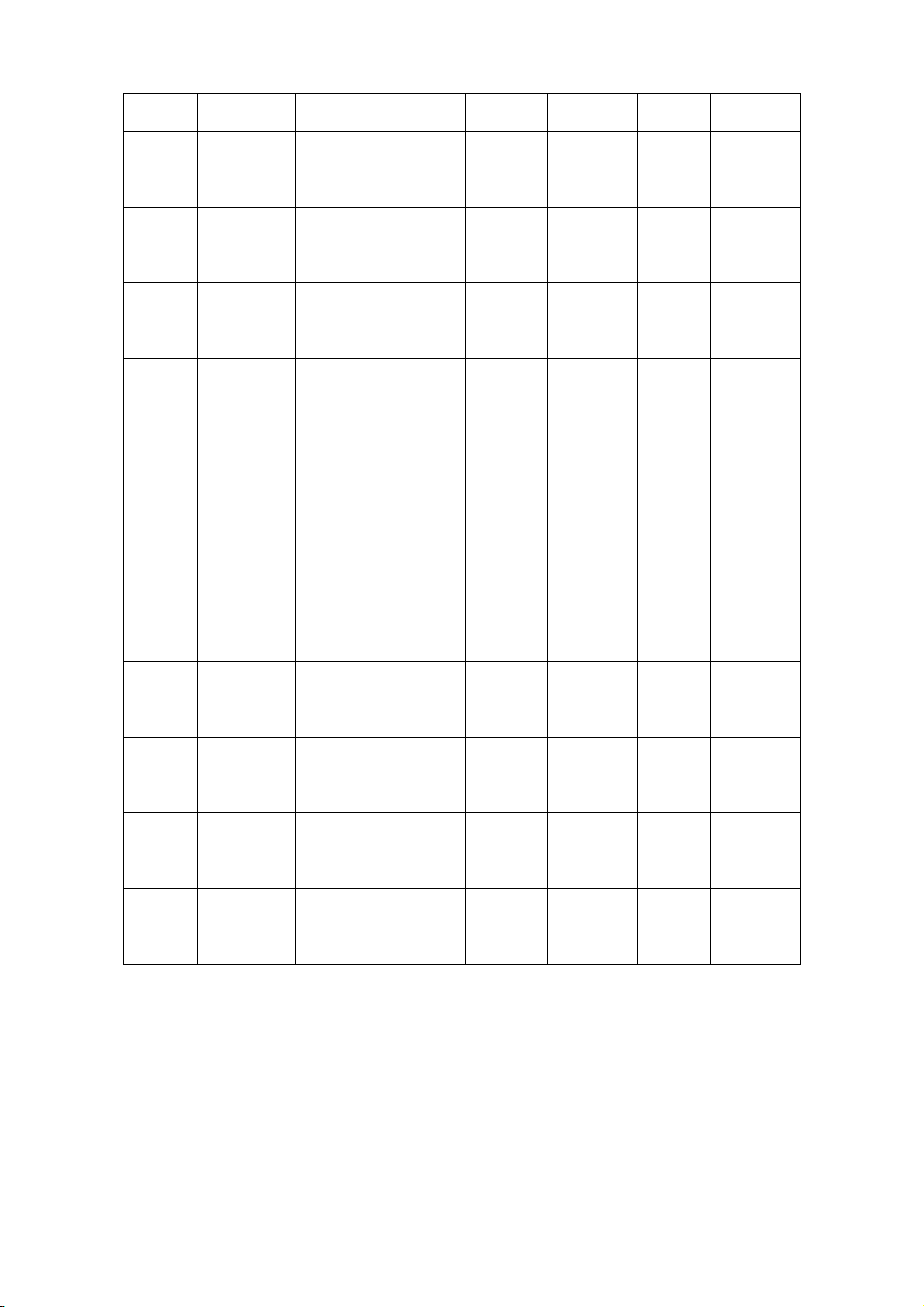
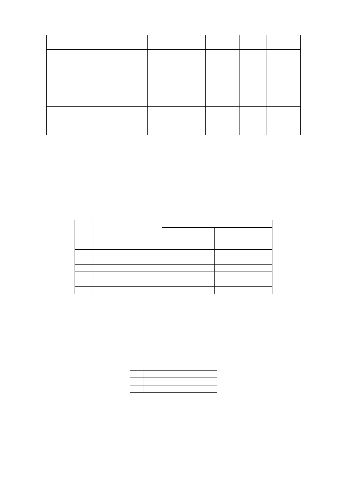
Following table shows the number of characters and input data capacity for the model 1 in version 1 to 14.
Version
1
2
3
4
5
6
7
8
9
10
11
Correction
level
L
M
Q
H
L
M
Q
H
L
M
Q
H
L
M
Q
H
L
M
Q
H
L
M
Q
H
L
M
Q
H
L
M
Q
H
L
M
Q
H
L
M
Q
H
L
M
Q
H
Data code
Word
19
16
13
9
36
30
24
16
57
44
36
24
80
60
50
34
108
82
68
46
136
106
86
58
170
132
108
72
208
160
128
87
246
186
156
102
290
222
183
124
336
256
208
145
Data bit Numeric
148
124
100
68
284
236
188
122
452
348
284
188
636
476
396
268
860
652
540
364
1084
844
684
460
1356
1052
860
572
1660
1276
1020
692
1964
1484
1244
812
2316
1772
1460
988
2684
2044
1660
1156
40
33
25
16
81
66
52
33
131
100
81
52
186
138
114
76
253
191
157
105
321
249
201
133
402
311
253
167
493
378
301
203
585
441
369
239
690
526
433
291
800
608
493
342
Alpha
numeric
24
20
15
10
49
40
31
20
79
60
49
31
113
84
69
46
154
116
95
63
194
151
122
81
244
188
154
101
299
229
183
123
354
267
223
145
418
319
262
176
485
368
299
207
Byte Kanji
17
14
11
7
34
28
22
14
55
42
34
22
78
58
48
32
106
80
66
44
134
104
84
56
168
130
106
70
206
158
126
85
244
184
154
100
287
219
180
121
333
253
205
142
10
8
6
4
20
17
13
8
33
25
20
13
48
35
29
19
65
49
40
27
82
64
51
34
103
80
65
43
126
97
77
52
150
113
94
61
177
135
111
74
205
156
126
87
D-F0382 NP-266/366 Product specifications Ver.1.10
35
Page 40
Version
12
13
14
Correction
level
L
M
Q
H
L
M
Q
H
L
M
Q
H
Data code
Word
384
292
244
165
432
332
276
192
489
368
310
210
Data bit Numeric
3068
2332
1948
1316
3452
2652
2204
1532
3908
2940
2476
1676
915
694
579
390
1030
790
656
454
1167
877
738
498
Alpha
numeric
555
421
351
236
624
479
398
275
707
531
447
302
Byte Kanji
381
289
241
162
429
329
273
189
486
365
307
207
1. The first code word is 4 bit length, and following all code words consist of 8 bit length.
2. Data bit numbers include “mode indicator” and “character number indicators”.
32) Printer status transmission : << ESC v >>
Code : [1B] h + [76] h
Sends current printer status
* Status to be transmitted consist of 1 byte and the content is explained in the chart
below.
bit Functions
0 1
Value
0 paper near empty paper present near empty
1 platen open normal head open
2 paper end paper present no paper
3 head temp. abnormal normal Temp. high
4 cutter problem normal cutter problem
5 Presenter error normal presenter error
6 Paper in presenter No Paper paper
7 Not defined
* Make sure that command is issued before transmission of print data.
(commands are stored in the input buffer and executed sequentially)
* Reception is available except in the buffer full status.
33) Inverted character set and reset : << ESC { n >>
Code : [1B] h + [7B] h + n * [00≤n≤FF] h
Sets or resets the inverted character function
* “n” is only valid for the LSB (b0)
* LSB (b0) has the following meaning
b0 Description
0 resets inverted character
1 sets inverted character
* The command is only valid when it is assigned at the beginning of a line.
* The default value of n is [00] h.
234
178
148
100
264
202
168
116
299
225
189
127
D-F0382 NP-266/366 Product specifications Ver.1.10
36
Page 41
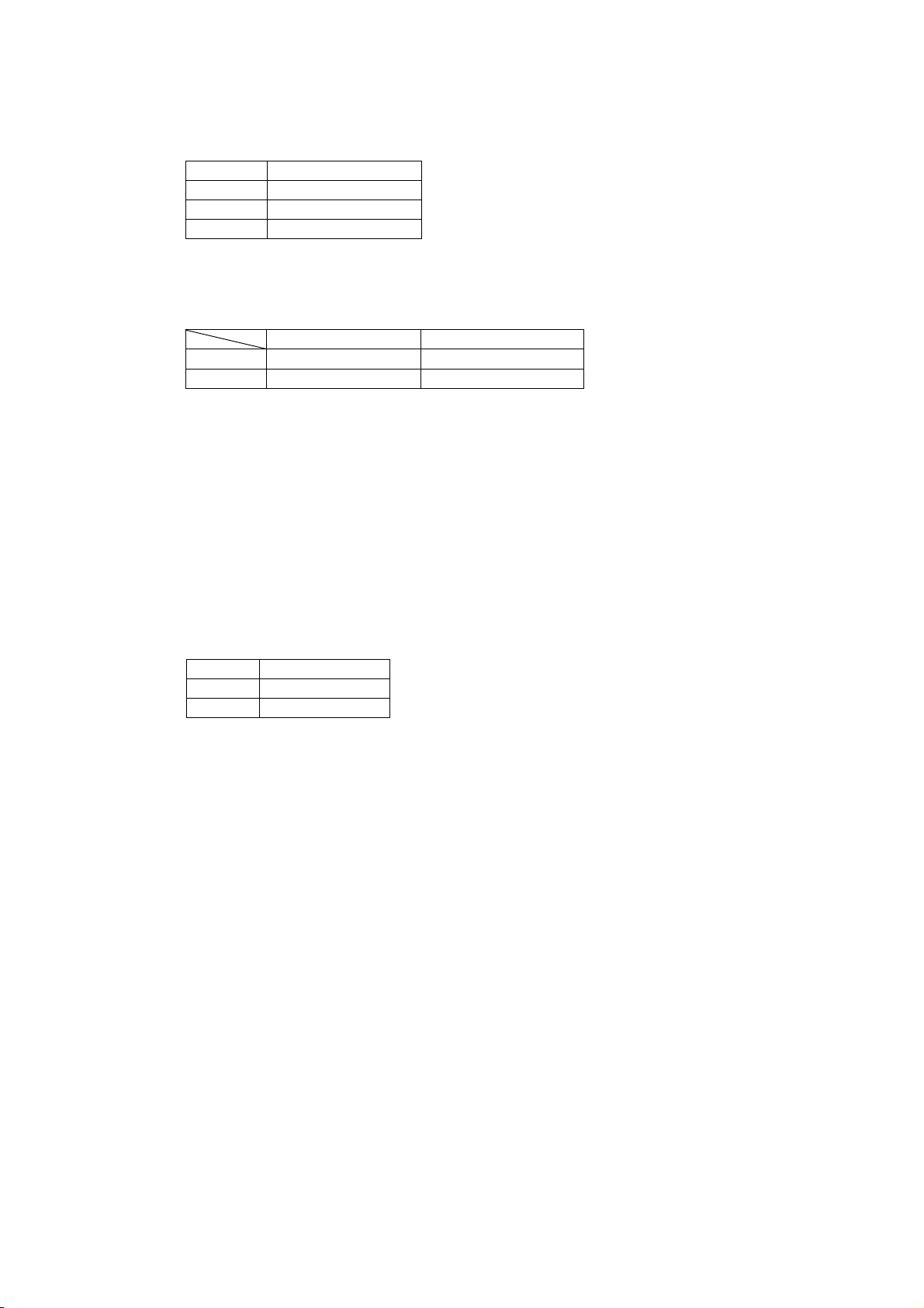
34) Partition drive select :<< GS % n >>
Code : [1D] h + [25] h + n * [01≤n≤03] h
Description : Selects partition drive.
* “n” indicates the following:
n(HEX) Divide
01 1 fixed partition
02 2 fixed partitions
03 automatic partition
* Default value is selected by the DIP switch (DS1-8) (2 partitions/Automatic partition).
* If assigned beyond the specified area, the data is neglected and the select will not
change.
* Automatic partition is as follows:
1 partition 2 partitions
NP-266 Less than 248 dots More than 249 dots
NP-366 Less than 352 dots More than 353 dots
35) Firmware download :<< GS d Dn >>
Code : [1D] h + [64] h + Dn
Description : Download printer firmware in hexadecimal code and rewrite firmware
according to the outcome.
* Dn is firmware’s hex code which complies with INTELLEX Hex format.
* When downloading is completed, the printer is activated with the new firmware rewritten.
36) Select of HRI character style :<< GS f n >>
Code : [1D] h + [66] h + n * [00≤n≤01] h
Description : Selects HRI character style in printing barcode
* “n” has the following meanings:
n (hex) Style
00 Font A
01 Font B
* Default value of “n” is [00] h.
37) Barcode height select :<< GS h n >>
Code : [1D] h + [68] h + n * [00≤n≤FF] h
Description : Selects barcode height by dot unit.
* “n” shows the vertical dot number
* Default value of “n” is [A2] h (162 dots)
* Assign “n” value so that it matches the barcode reader specification for readable area.
D-F0382 NP-266/366 Product specifications Ver.1.10
37
Page 42
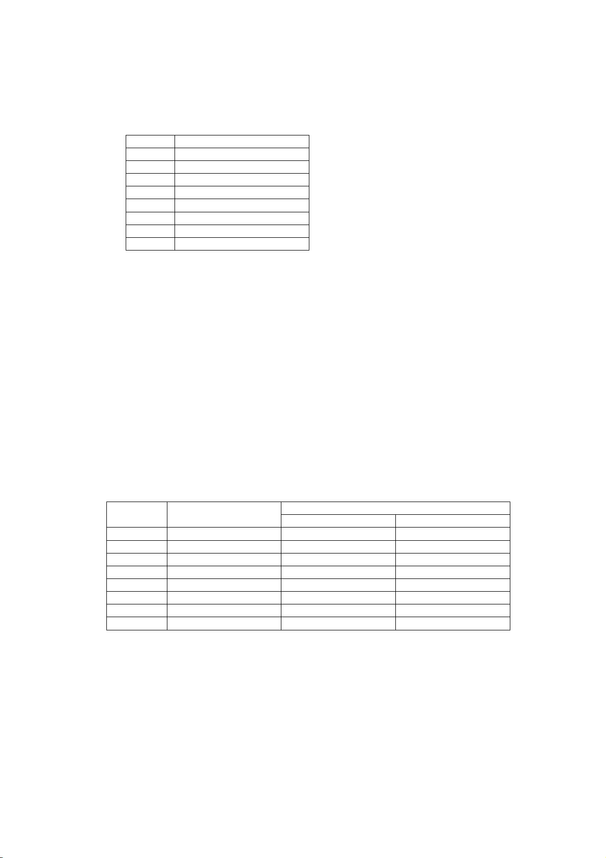
38) Barcode print : << GS k n Dn NUL >>
Code : [1D] h + [6B] h + n + Dn + [00] h * [00≤n≤07] h
Description : Selects barcode symbology and prints barcode.
* The next print start position is on the line head
* Select following barcode symbology with “n” value.
* Dn indicates the character code to be printed.
n (Hex) Barcode symbology
00 UPC-A
01 UPC-E
02 EAN-13 (JAN-13)
03 EAN-8 (JAN-8)
04 CODE 39
05 ITF
06 CODABAR (NW-7)
07 CODE128
* If the print character numbers are fixed in the barcode symbology, the input character
numbers should match the print character numbers.
* If horizontal data exceed one line, the exceeded data cannot be printed.
39) Barcode width size select :<< GS w n >>
Code : [1D] h + [77] h + n * [02≤n≤04] h
Description : Selects width of barcode
* Default value of “n” is [03] h.
40) Automatic transmission of printer status: << GS v NUL >>
Code : [1D] h + [76] h + [00] h
Description : Automatically transmits the status when the printer status changes.
*Once setting is made, it is effective until software is reset, power is set off, or reset signal
is input.
*The commands are stored in the internal receive input buffer and executed sequentially.
*Status of transmission is one byte and functions are explained below.
Bit Function
0 1
Value
0 Paper near empty Paper present Near empty
1 Platen open Normal Open
2 Paper end Paper present Paper end
3 Head temp. too high Normal Head temp. too high
4 Cutter problem Normal Cutter problem
5 Presenter error Normal Presenter error
6 Paper in presenter No Paper paper
7 Not defined
D-F0382 NP-266/366 Product specifications Ver.1.10
38
Page 43
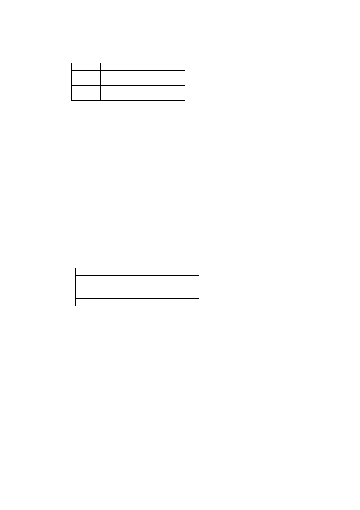
41) Select of HRI character print position :<< GS H n >>
Code : [1D] h + [48] h + n * [00≤n≤03] h
Description : Selects the print position of HRI characters in printing barcode.
* “n” has the following meaning.
n (Hex) Print position
00 No printing
01 Above barcode
02 Below barcode
03 Above and below barcode
* HRI characters are the characters selected by “HRI character style select”.
* Default value of “n” is [00] h.
42) NV bit image print :<< GS P n >>
Code : [1D] h + [50] h + Dn * [00≤n≤02] h
Description : Prints the bit image print data registered.
* Selects one of the print pattern among three registered patterns by assigning 0 to 2
value of “n”.
43) NV bit image registration :<< GS T n >>
Code : [1D] h + [54] h + n
Description : Register the predetermined bit image print data.
* It is possible to register from 0 to 2 different kinds of patterns (3 patterns).
* In each pattern, up to the maximum of 150mm length for NP-266 and 110mm length for
NP-366 of bit image print data can be registered. The bit image print data exceeding the
maximum length is neglected.
* The registered data is not erased even though off/on of the power, initialization of printer
and software reset are executed.
* “n” has a following meanings.
n (hex) Function
00 Start of pattern 0 registration
01 Start of pattern 1 registration
02 Start of pattern 2 registration
FF End of registration
* When registrations started in the middle of a line, whole line is registered.
* When registration ended in the middle of a line, whole line is not registered.
* Following is a command sequence of pattern 0 registration.
GS T [00] h + (bit image data assigned by ESC * + ESC J n) x m lines + GS T [FF] h
44) Print density set : << GS ~ n >>
Code : [1D] h + [7E] h + n * [41≤n≤87] h
Description : Sets print density in the range between 65% ~ 135% of the standard value,
DS1-4 Off.
* “n” ranges from [41] h(65%) to [87] h(135%). However, set it for actual use in the range
[41] h(65%) to [82] h(130%).
* At the initial status, 100% or 125% can be selected by the DIP switch, DS1-4.
* This command has priority over the setting by DIP switch.
D-F0382 NP-266/366 Product specifications Ver.1.10
39
Page 44
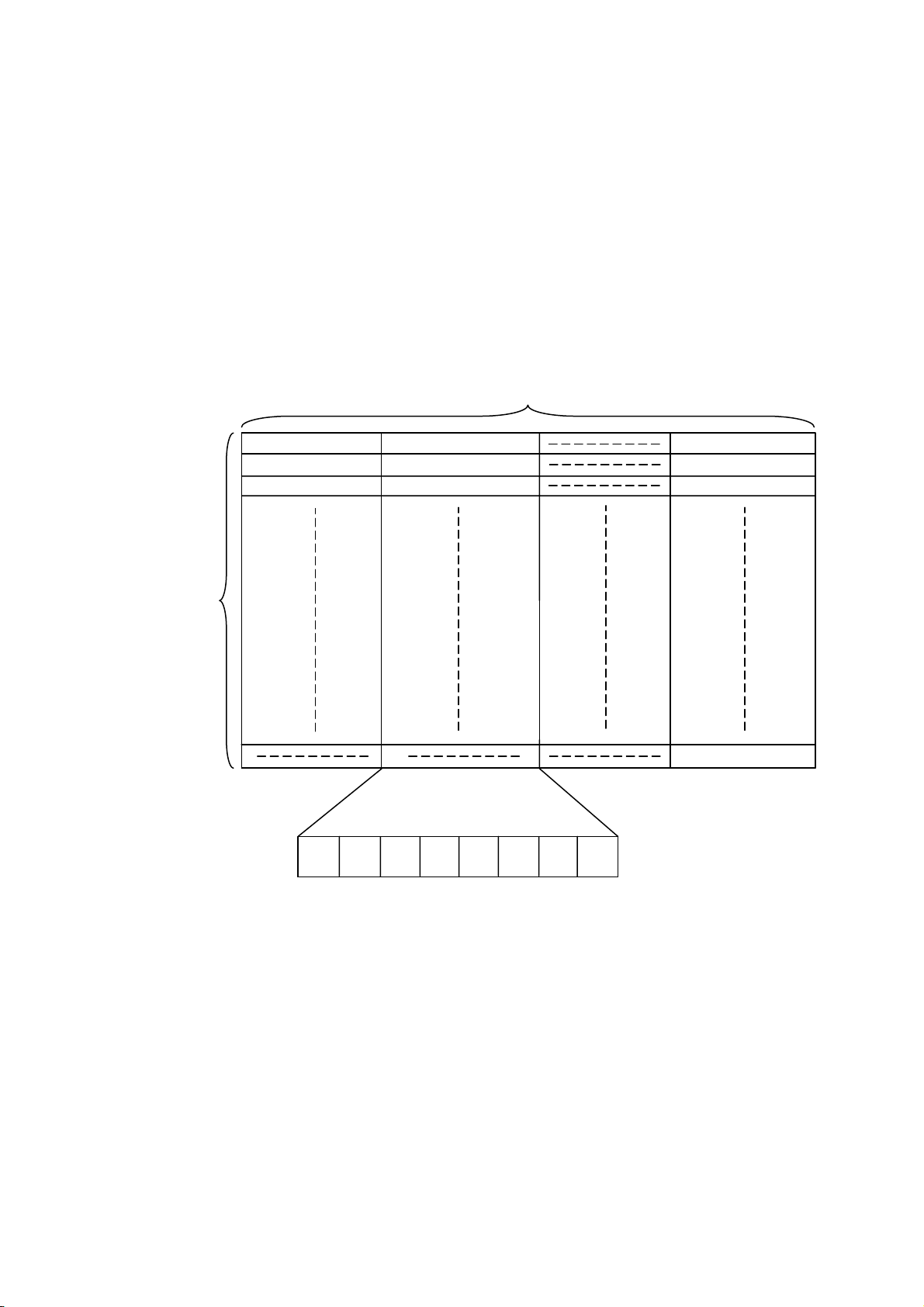
45) Raster bit image : << ESC b n1 n2 n3 Dn >>
Code : [1B] h + [62] h + n1 + n2 + n3 + Dn
* [01≤n1≤36] h : NP-266
* [01≤n1≤48] h : NP-366
* [00≤n2≤FF] h
* [00≤n3≤FF] h
Data is printed in a raster bit image.
・Dn is a raster bit image data.
・The printer prints raster bit image of width n1 byte by height n2+(256*n3) dot lines.
・The total byte of the requested raster bit image data (Dn) is n1*(n2+(256*n3)).
・Raster bit image data (Dn) exceeding the printing field will be disregarded.
・Raster bit image data (Dn) interprets bit”1” as print and bit”0” as not print.
・Relation between raster bit image data (Dn) and printed dots are as follows.
n1 byte
D1 D2 Dn1
Dn1+1 Dn1+2 Dn1*2
Dn1*2+1 Dn1*2+2 Dn1*3
n2+(256*n3)dots
Dn1*(n2+(256*n3))
MSB LSB
・Please add the command of 《ESC J 00h》(〔1B〕h+〔4A〕h+〔00〕h) at the end.
・If you send this command consecutively, please add 《ESC J n》(n≠〔 00〕h) at the end of
each image, and add the《ESC J 00h》at the very end of the image.
D-F0382 NP-266/366 Product specifications Ver.1.10
40
Page 45
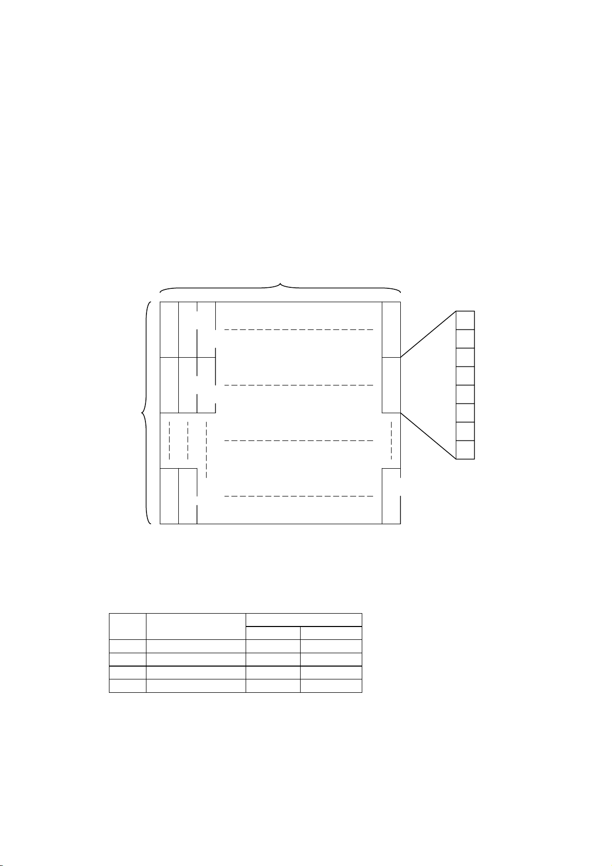
46) Download bit image definition :<< GS * n1 n2 Dn >>
Code : [1D] h + [2A] h + n1 + n2 + Dn * [01≤n1≤FF] h
* [01≤n2≤30] h
* [n1 x n2≤d80] h
Description : Defines “download bit image” of number of dots specified by n1 and n2.
* Horizontal dot numbers are obtained by n1 x 8 and vertical dot numbers by n2 x 8.
* Dn is bit image data.
* Once “download bit image” is defined, it is valid until it’s redefined, a download
character is defined, and external characters are specified, a software is reset, power is set
off.
* “Download bit image” cannot be defined at the same time with “download
characters” or “external characters”. If this command is executed, “download
character definition” or “external characters contents” are cleared.
* The relationship between bit image data & defined dots is shown below.
n1x8dots
d1 MSB
dn2+1
dn2x2+1
d2
dn2+2
dn2x2+2
n2x8dots
LSB
dn2 dn1xn2x8
dn2x2
47) Download bit image print :<< GS / m >>
Code : [1D] h + [2F] h + m * [00≤m≤03] h
Description : Prints “download bit image” in a mode assigned by “m”.
* Modes to be assigned by m are as follows.
m(hex) Modes
Dot density
Vertical Horizontal
00 Normal mode 203 dpi 203 dpi
01 Double width 203 dpi 101 dpi
02 Vertical double 101 dpi 203 dpi
03 Quadruple 101 dpi 101 dpi
* If there are some data left in the print buffer, this command is neglected.
* If “download bit image” is not defined yet, this command is neglected.
* “Download bit image” data exceeding 1 line cannot be printed.
* Print modes (bold, double stike, inverted ) except Alignment is not affected.
*Alignment is only valid to download bit image within print area.
D-F0382 NP-266/366 Product specifications Ver.1.10
41
Page 46

48) Presenter cramp compulsory eject :<< ESC r 0 >>
Code : [1B] h + [72] h + [30] h
Description : Paper cramped in the presenter eject totally.
* This command is effective for A type.
49) Presenter retraction time setting :<< ESC r 1 n >>
Code : [1B] h + [72] h + [31] h + n * [00≤n≤3C] h
Description : Set time to retract the paper cramped in the presenter.
* The time can be set by n as follows.
The time to retract = n x 1.0 sec.
* Default value of n is [04] h.
D-F0382 NP-266/366 Product specifications Ver.1.10
42
Page 47
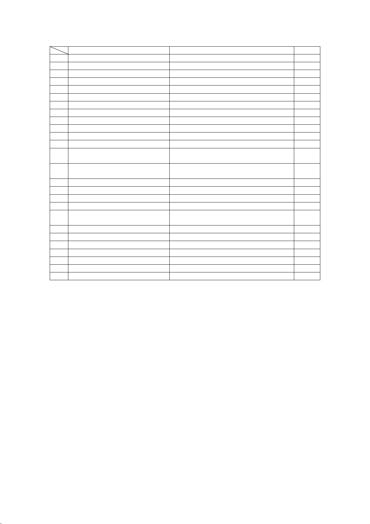
5.4 Page mode command table
Command Function Pages
1 ESC L n Print & edit selection 44
2 ESC M nx1 nx2 nx3 ny1 ny2 ny3 Print edit position setting 46
3 FF Print page feed 48
4 LF Line feed 48
5 ESC c Printer initialization 48
6 ESC I Print/edit clear 48
7 GS ~ Print density setting 48
8 ESC I n1 n2 n3 Set page length 48
9 ESC A n1 n2 Line space setting 49
10 ESC W n Character width enlarge setting 49
11 ESC w n Vertical enlarge print setting 49
12 ESC g n1 n2 Vertical/horizontal character enlarge set 49
13 SO w
14 SO W
Double width enlarge print setting with
auto reset
Quadruple enlarge print setting with auto
reset
49
49
15 ESC $ n1 n2 Absolute position setting 50
16 ESC * m n1 n2 Dn Bit image mode set 50
17 GS T n NV bit image pattern registration 51
18 ESC F n NV bit image double strike setting 51
GS b n1 nx1 nx2 nx3
19
ny1 ny2 ny3 n4 Dn LF
Barcode print edit 51
20 GS w n Barcode width setting 52
21 GS h n1 n2 Barcode height setting 52
22 GS H n HRI character print/edit setting 52
23 GS X n1 n2 n3 n4 Barcode modification total settings 52
24 ESC v Send printer status 52
25 GS d Dn Firmware download 52
26 ESC S Line mode selection 52
* The characters covered in the section “ “ at the page mode command parameter are ASCII.
For example:
'1' = [31] h
'02' = [30] h + [32] h
* The first line start position means the start position of the first line for print/edit direction selected at
that time.
D-F0382 NP-266/366 Product specifications Ver.1.10
43
Page 48
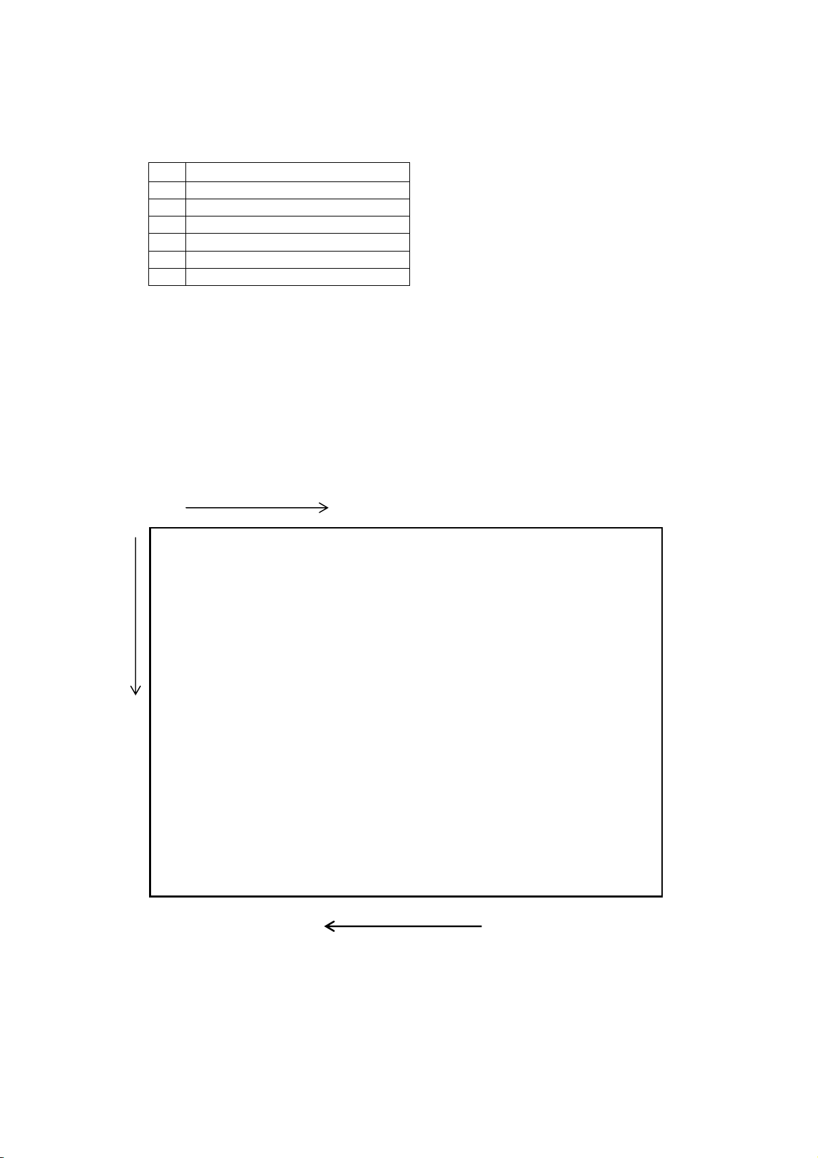
5.5 Page mode command details
1) Print/edit direction select : << ESC L n >>
Code : [1B] h + [4C] h + n * ['0'≤n≤'5']
Description : Selects the print/edit direction selected in the print/edit page.
* Print/edit direction set by “n” value and axis are:
n
Description
'0' Sets 0 for print/edit
'1' Sets 1 for print/edit direction
'2' Sets 2 for print/edit direction
'3' Sets 3 for print/edit direction
'4' Sets 4 for print/edit direction
'5' Sets 5 for print/edit direction
* For print/edit direction layout, refer to the drawings below and the next page.
* The default value of “n” is “1”.
* Once print/edit direction is changed, the next print/edit position will be at the start of line.
* The other settings remain unchanged. The command setting will not change after printer
initialization.
Print/Edit Layout
< Print/Edit direction 0, 3 >
X Direction
(0,0)
Print/edit direction 0/1st line Print
Y
Print/edit direction 0/2nd line Edit
Print/edit direction 0/3rd line Directions
3/1st line
3/2nd line
3/3rd line
Paper feed direction
D-F0382 NP-266/366 Product specifications Ver.1.10
44
Page 49
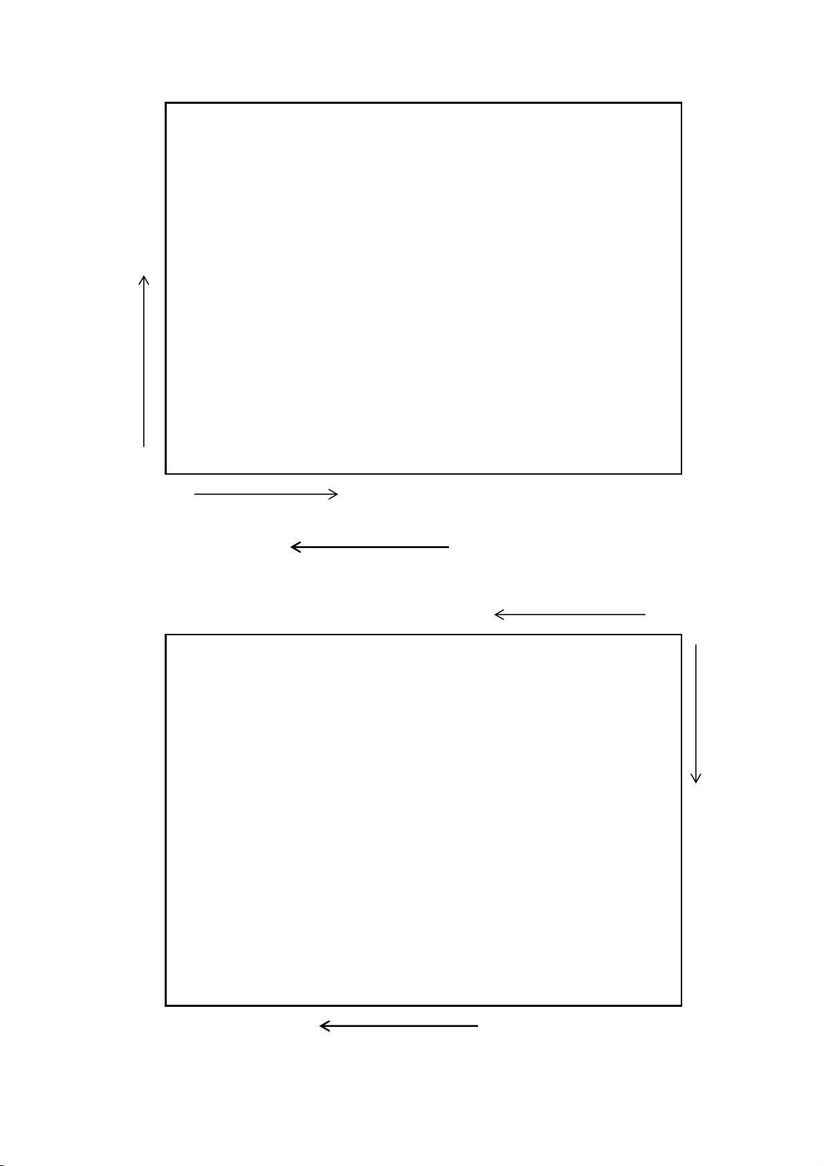
< Print/Edit direction 1, 4 >
X
Print/edit direction 4/ 1st line
Print/edit direction 4/ 2nd line
Print/edit direction 4/ 3rd line
Print
Edit
Direction
1/1st line
1/2nd line
1/3rd line
(0,0)
Y direction
Paper feed
< Print/edit direction 2, 5 >
y
(0,0)
3 2 1
Lines
Direction
5 5 5
/ / /
Print
Edit
Print/edit direction 2/1st line
Print/edit direction 2/2nd line
Print/edit direction 2/3rd line
Paper feed direction
x
D-F0382 NP-266/366 Product specifications Ver.1.10
45
Page 50
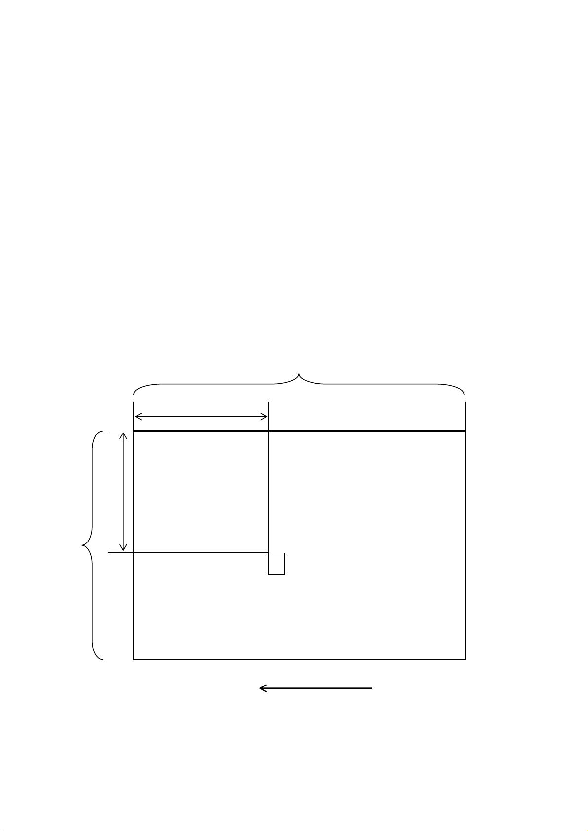
2) Print/edit position setting : << ESC M nx1 nx2 nx3 ny1 ny2 ny3 >>
Code: [1B] h + [4D] h + nx1 + nx2 + nx3 + ny1 + ny2 + ny3
For < print/edit direction 0, 3 > * ['000'≤nx1nx2nx3≤’150’] NP-266
* ['000'≤ny1ny2ny3≤’054’] NP-266
* ['000'≤ny1ny2ny3≤’110’] NP-366
* ['000'≤ny1ny2ny3≤’072’] NP-366
For < print/edit direction 1, 2, 4, 5 > * ['000'≤nx1nx2nx3≤’054'] NP-266
* ['000'≤ny1ny2ny3≤’150'] NP-266
* ['000'≤ny1ny2ny3≤’072’] NP-366
* ['000'≤ny1ny2ny3≤’110’] NP-366
The next print/edit position is specified by “x” and “y” axis (mm).
* The upper left corner is (x, y) = (0, 0)
* The upper left end of the next print/edit character is positioned at the axis specified.
* “x” axis value is specified by nx1, nx2 and nx3
Example: If 8mm is specified, nx1='0'、nx2='0'、nx3='8'
* “y” axis value is specified by ny1, ny2 and ny3
Example: If 135mm is specified, ny1='1'、ny2='3'、ny3='5'
Print/edit position when (x, y) axis are specified.
< Print/edit direction 0, 3 >
Max. 150mm (Changeable depending on page length)
xmm
(0,0)
54m
ymm
(x,y) Print/edit character position
A
Paper feed direction
D-F0382 NP-266/366 Product specifications Ver.1.10
46
Page 51
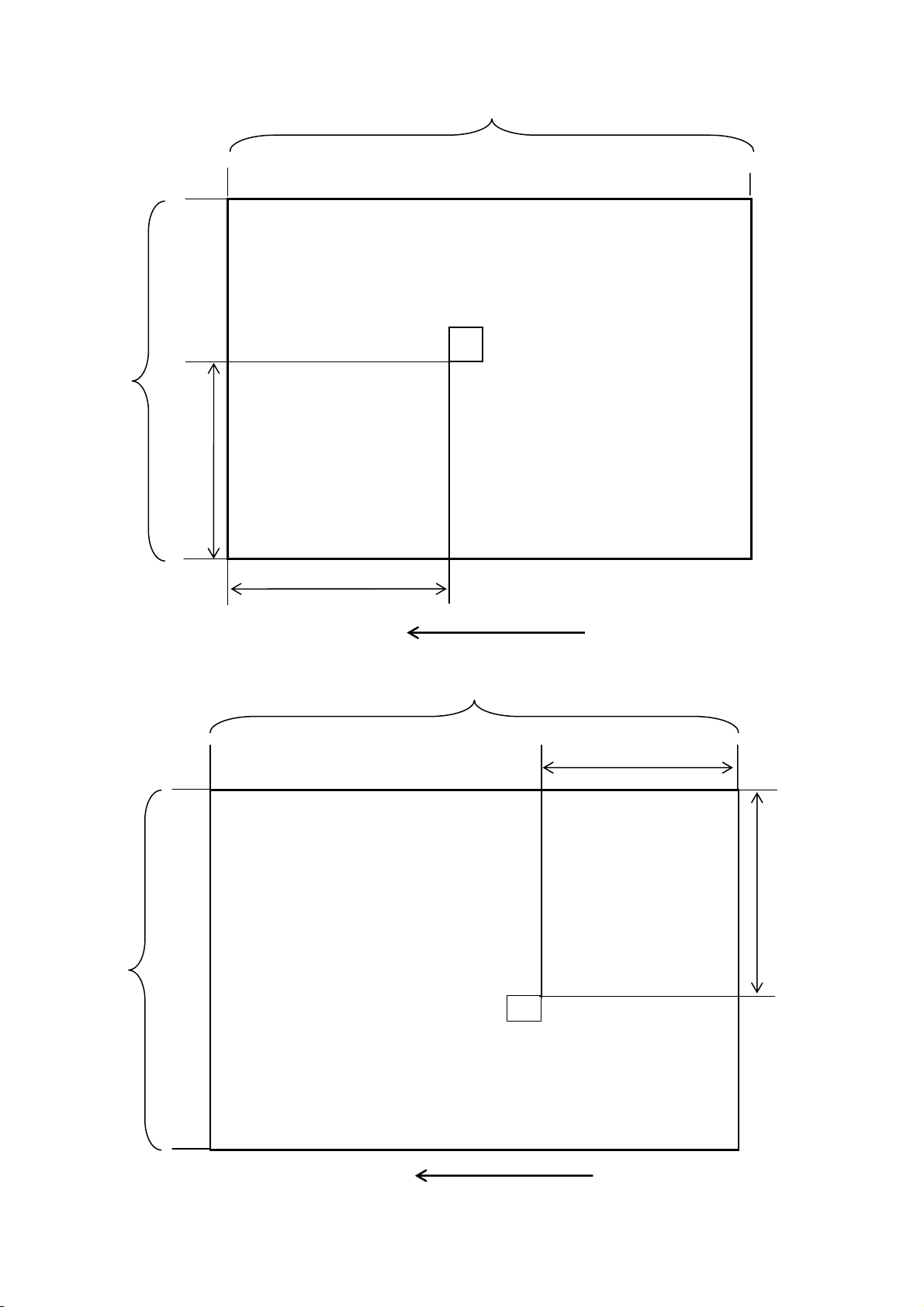
< Print/edit direction 1, 4 >
Max. 150mm (Changeable depending on page length)
54mm
(0,0)
y mm
< Print/edit direction 2, 5 >
Max.150 mm (Changeable depending on page length)
ymm
54mm
X mm
(x,y)Print/edit character position
Print/edit character position (x,y)
A
Paper feed direction
A
Paper feed direction
(0,0)
xmm
D-F0382 NP-266/366 Product specifications Ver.1.10
47
Page 52

3) Print page feed : << FF >>
Code: [0C] h
Prints the data in the page buffer selected in the print/edit page.
* The data in the page buffer is not cleared after printing.
* The next print/edit position will be at the start position of the line.
4) Line feed : << LF >>
Code: [0A] h
Moves the print/edit position to the start position of the next line.
The line feed amount at this time will be:
< print/edit direction 0, 1, 2 > : height of character + line space
< print/edit direction 3, 4, 5 > : width of character + line space
Printing is not executed until “print page feed” is input.
5) Printer initialization : << ESC c >>
Code: [1B] h + [63] h
Clears the print data stored in the all page buffer and resets each setting to the default values.
* The data in the reception input buffer is not cleared.
* Please refer to the section 5.7 Mode status of setting function (Page mode) <ESC c> for the
other function settings.
* The next print/edit position will be at the start position of line of the page 0.
6) Print/edit page clear : << ESC I >>
Code: [1B] h + [49] h
Clears the print data stored in the page buffer selected in the print/edit page.
* Each setting is not cleared.
* The next print/edit position will be at the start position of line.
7) Print density setting : << GS ~ n >>
Code: [1D] h + [7E] h + n * [41≤n≤87] h
Make a setting for the print density between 65% and 135% from the standard print density of
(DS1-4 OFF).
* Make a setting between [41]h (65%) ~ [82]h (130%) in actual use, although the range of “n” is set
between [41]h (65%) ~ [87]h (135%)
* By the DIP SW setting of (S2-1), you can set the default status for 100% or 125%.
* This command takes priority over the DIP SW settings.
8) Set page length : << ESC I n1 n2 n3 >>
Code: [1B] h + [6C] h + n1+ n2 + n3 * ['012’ ≤n1n2n3≤'150’]
Set the page range (where printing and editing is possible) by mm.
*The next print/edit position will be at the start position of line of the selected page.
*Data in the Page Buffer will not be cleared.
*The default status of page length is '150'mm
* ’110’mm for NP-366
D-F0382 NP-266/366 Product specifications Ver.1.10
48
Page 53
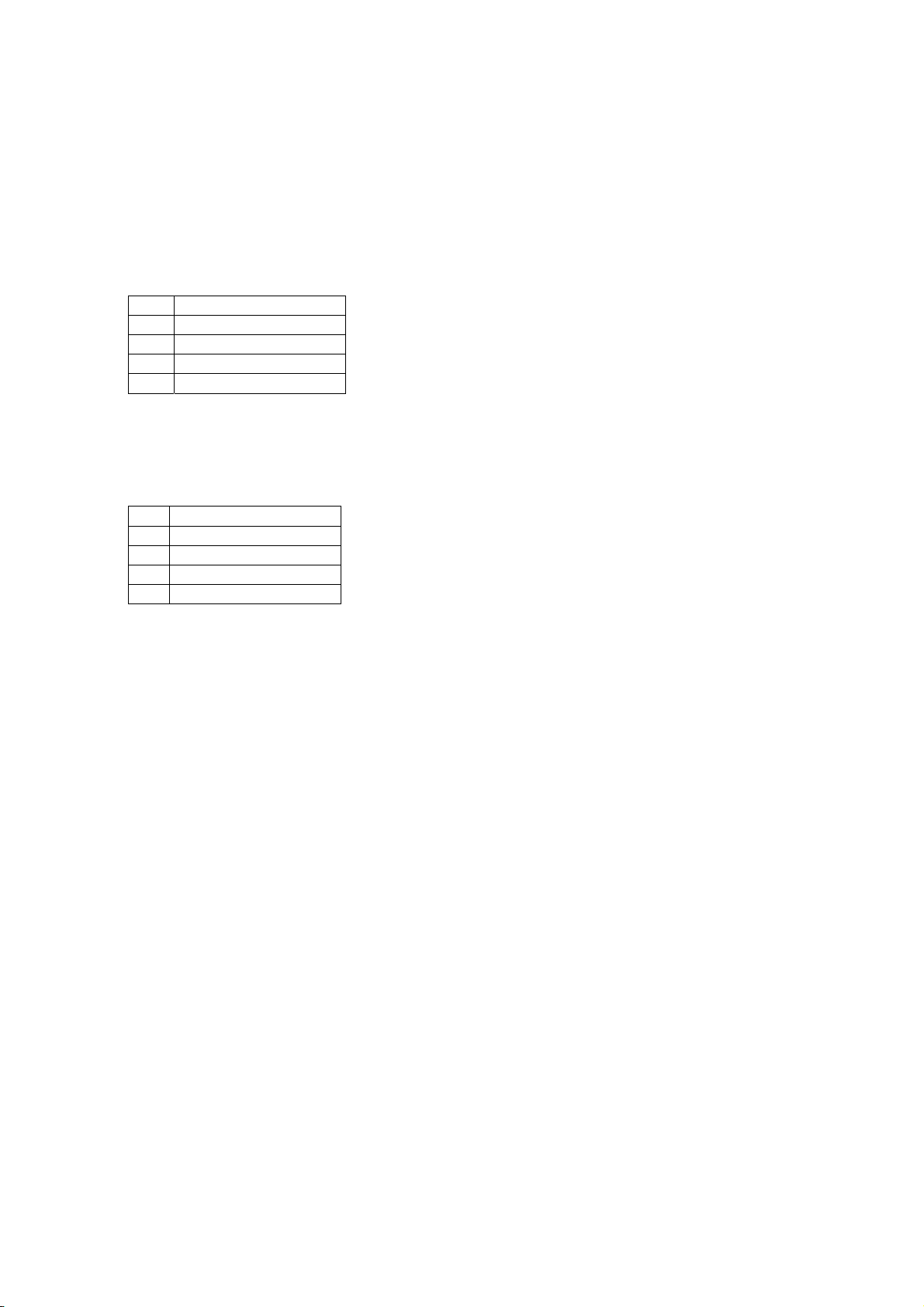
9) Line space setting : << ESC A n1 n2 >>
Code: [1B] h + [41] h + n1 + n2 * [‘00’≤n1n2≤’16’]
Make a setting for line space for characters.
* The line space that can be set is n1n2 (mm).
* The default value of n1n2 is’ 00’.
10) Width enlarge print setting : << ESC W n >>
Code: [1B] h + [57] h + n * [‘1’≤n≤’4’]
Sets the width enlargement number for the following print/edit characters.
The enlargement by n value is:
n Enlargement
‘1’ X 1 (reset)
‘2’ X 2
‘3’ X 3
‘4’ X 4
11) Vertical enlargement setting : << ESC w n >>
Code: [1B] h + [77] h + n * [‘1’≤n≤’4’]
Sets the height enlargement number for the following print/edit characters.
The enlargement by n value is:
n Enlargement
'1' X 1 (reset)
'2' X 2
'3' X 3
'4' X 4
12) Width/height enlargement settings : << ESC g n1 n2 >>
Code: [1B] h + [67] h + n1 + n2 * [‘1’≤n1≤’4’]
Set the width/height enlargement for the next print/edit characters. * [‘1’≤n2≤’4’]
* Set the width enlargement value by n1 value. (same manner with section 10 above)
* Set the height enlargement value by n2 value. (same manner with section 11 above)
13) Double width enlarge print setting with auto reset : << SO w >>
Code: [0E] h + [77] h
Double width setting of the print/edit characters.
* The only next one character after the command will be effective and the second one and after
will be effective in the single width enlarge print settings.
14) Quadruple print setting with auto reset : << SO W >>
Code: [0E] h + [57] h
The next print/edit characters are enlarged (width is doubled and height is doubled)
* The only next one character after the command will be effective and the second one and after
will be effective in the single width/height enlargement settings.
* Enlargement will be made from the lower left position of each character to the upper right direction.
D-F0382 NP-266/366 Product specifications Ver.1.10
49
Page 54
15) Absolute position setting : << ESC $ n1 n2 >>
Code: [1B] h + [24] h + n1 + n2 * [00≤n1≤FF] h
The next print/edit position is specified by the dot numbers from the line start. * [00≤n2≤04] h
* Print total dots divided by 256, quotient is n2 and remainder is n1.
* The print/edit position will be at n1 + (256 x n2) from the start position.
* The specified position, exceeding the end of line is disregarded.
16) Bit image mode setting : << ESC * m n1 n2 Dn >>
Code: [1B] h + [2A] h + m + n1 + n2 + Dn * [m = 23]h fixed
* [00≤n1+(100hxn2) ≤1b0] h : NP-266
* [00≤n1+(100hxn2) ≤240] h : NP-366
Data is printed in 24 dot bit image of resolution of 203 x 203DPI.
z Print total dots divided by 256, quotient is n2 and remainder is n1.
z Total dots in bit image mode are n1 + (256 x n2).
z If the bit image input data exceeds 1 dot/line (432 dots) position, the exceeded data will be
disregarded and it is not automatically printed in the next line.
z Bit image data (Dn) interprets bit 1 as print and bit 0 as not print.
z The total dots to be printed in the bit image must be the same with quantity of bit image
data that corresponds to the dots. If quantity of bit image data is less than the total dots,
the same amount of following data, same as the balance, is treated as bit image data. If it
is more than the total dots, the same exceeding volume of bit image data will be treated
as normal data.
z This command is effective only in case of “Print/Edit direction 1”.
The relationship between the bit image data and dots to be printed
・24 dot bit image (drawing of 24dots density)
D1 D4 D7 MSB
D1 D2 D3 D7 D8 D9
D4
D5 D6
D2
D5
D8
D3
D6 D9
LSB
Print Data
=1dot
D-F0382 NP-266/366 Product specifications Ver.1.10
50
Page 55
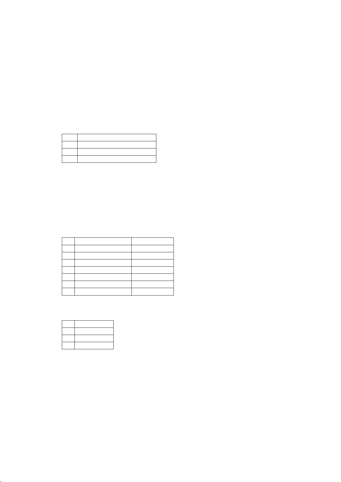
17) NV bit image pattern register : << GS T n >>
Code: [1D] h + [54] h + n *['1'≤n≤'2']
Register contents of page buffer as NV bit image pattern.
* It is necessary to write the data to be registered in the page buffer. Printing is not needed.
* There are two patterns able to be registered. (Selected by ‘n’ value)
* The registered data is effective until it is re-registered.
* Once registered, power on/off , printer initialization does not clear the data.
18) NV bit image pattern lay over : << ESC F n >>
Code: [1B] h + [46] h + n * ['0'≤n≤'2']
Specifies if the previously registered NV bit image pattern should be laid over to print (OR print),
at printing the data by Print page feed <FF>.
* n means as follows:
n Function
'0' Clears lay over
‘1’ Set lay over pattern 1
'2' Set lay over pattern 2
* This command specification is effective until it is reset, execute <printer initialization>, the
power is set off.
* The default value of n is '0'.
19) Barcode print/edit : << GS b n1 nx1 nx2 nx3 ny1 ny2 ny3 n4 Dn LF >>
Code: [1D] h + [62] h + n1 + nx1 + nx2 + nx3 + ny1 + ny2 + ny3 + n4 + Dn + [0A] h
Selects barcode structure and print/edit * ['0'≤n1≤'6']
* Selects the following barcode structure by n1 value: * ['0'≤n4≤'2']
n1 Barcode structure Characters
'0' UPC-A 12
'1' UPC-E 12
'2' JAN-13(EAN-13) 13
'3' JAN-8(EAN-8) 8
*['000'≤nx1nx2nx3≤'150'] NP-266
*['000'≤ny1ny2ny3≤'150'] NP-266
*['000'≤nx1nx2nx3≤'110'] NP-366
*['000'≤ny1ny2ny3≤'110'] NP-366
'4' CODE39 Changeable
'5' ITF 14, 16
'6' CODABAR Changeable
* Specifies x axis (mm) for print/edit position by nx1, nx2 and nx3 and y axis (mm) by ny1, ny2
and ny3. It specifies in the same manner as Print/edit position setting.
* The following rotation is specified by n4 value.
n4 Rotates
'0' 0 degree
'1' 90 degree
'2' 270 degree
* Dn indicates the character code to be printed.
* If the character code (Dn) cannot be printed, the data after the code is treated as the
non-specified data.
* If a barcode is selected with character volume fixed, it needs to match to the character volume.
* If the barcode exceeds the size of page, print/edit of the barcode is not executed.
* The print/edit position for the general characters does not move after barcode print/edit.
D-F0382 NP-266/366 Product specifications Ver.1.10
51
Page 56
20) Barcode width size setting : << GS w n >>
Code: [1D] h + [77] h + n *['2'≤n≤'4']
Specifies the width of barcode.
* The default value of n is '3'.
21) Barcode height setting : << GS h n1 n2 >>
Code:[1D] h + [68] h + n1 + n2 * ['01'≤n1n2≤'70']
Specifies the height of barcode (mm).
* n1n2 indicates the height of barcode in mm.
* The default value of n1n2 is '20'.
22) HRI characters print/edit setting : << GS H n >>
Code: [1D] h + [48] h + n * ['0'≤n≤'1']
* Specify print/edit of HRI characters in case print/edit of barcode is executed.
* The edit by n value is specified as follows:
n Print/edit
'0' No print/edit
'1' Print/edit below barcode
* The default value of n is '0'.
23) Barcode modification total setting : << GS X n1 n2 n3 n4 >> * ['0'≤n1≤'1']
Code: [1D] h + [58] h + n1 +n2 + n3 + n4 * ['2'≤n2≤'4']
Totally sets the modification of barcode for print/edit * ['01'≤n3n4≤'70']
* n1 is the same with the parameter of “HRI character print/edit setting”, n2 is the same with
parameter of “Barcode width size setting” and n3n4 the same with parameter of “Barcode height
setting”.
24) Send printer status : << ESC v >>
Code: [1B] h + [76] h + n
For the detail, please refer to [Send printer status] of line mode command.
25) Firmware download : << GS d Dn >>
Code: [1D] h + [64] h + Dn
For the detail, please refer to [Firmware download] of line mode command.
26) Line mode selection : << ESC S >>
Code: [1B] h + [53] h
Switched between the line mode and page mode.
* The data in the page buffer is cleared.
* The page mode setting will be the same as the status on the printer initialization < ESC c >.
* The default value is ‘Line mode.
D-F0382 NP-266/366 Product specifications Ver.1.10
52
Page 57
5.6 Mode status of setting functions (Line mode)
Setting function Power ON Command ESC @ DLE CAN Remarks
Print line buffer Clear
Internal receive buffer Clear
Assign horizontal tab
Page length 66 lines Optional 66 lines 66lines
Line pitch 34/203 in. Optional 34/203 in. 24/203 in
Assign right space to
character
Assign all print mode 00(h) Optional 00(h) 00(h) Notes 1,2,3
Define download
characters
Assign/clear
download
character set
Assign/clear underline Clear Optional Clear Clear Note 2
Underline width by
[Assign all print mode]
Assign/clear double
strike character
Assign/clear bold
character
International
character
FEED Switch
effective/not effective
Select Character
code table
Assign/clear inverted
character
90°clockwise rotation
character assign/clear
Select barcode width 3 dots Optional 3 dots 3 dots 1 module=3 dots
Select barcode height 162 dots Optional 162 dots 162 dots
Select print position of
HRI character
Select style of HRI
character
Data input control Effective Optional Keep Effective
Align position align to left edge Optional
Auto-transmission of
Printer status
NV bit image
registration
Partition drive
selection
Print Density setting DS1-4 Optional keep DS1-4
Definition of download
bit image
Presenter retraction
time setting
registered/regist-ered(Flash
not register / register(flash
Font A.4
positions
0 dot Optional 0 dot 0 dot
Not
ROM)
Clear Optional Clear Clear
1 dot
Clear Optional Clear Clear Note 3
Clear Optional Clear Clear Note 3
8 (Japan) Optional 8 (Japan) 8 (Japan)
effective Optional effective effective
DS1-5 Optional
Clear Optional Clear Clear
Clear Optional Clear Clear
0: no print Optional 0: no print 0: no print
Font A Optional Font A Font A
not effective
ROM)
DS1-8 optional keep DS1-8
Not registered optional Clear Clear
4sec. optional keep 4sec.
ESC@/DLE
CAN
Software
reset
Optional
Optional Keep Keep
the same
width used
last time
cannot
change from
“effective” to
“not effective”
optional keep keep
Clear Clear
Keep Clear
Font A.4
positions
1 dot 1 dot
DS1-5
Note 4
align to left
edge
Keep not effective
Font A.4
positions
DS1-5
Align to left
edge
NP-366 Font A 5
positions
Effective by one
line unit
Effective by one
character unit
【 Printer
status transmit】
will have no
effect
registered in
Flash Rom
Please refer to next page for note.
D-F0382 NP-266/366 Product specifications Ver.1.10
53
Page 58
5.7 Mode status of setting functions (Page mode)
Setting function Power ON Command ESC c Remarks
Page buffer Clear ESC c/ ESC I Clear
Internal receive buffer Clear Not applicable Keep
Select print edit direction ‘1’ Optional ‘1’
Setting page length 150mm Optional 150mm NP-366: 110 mm
Space between lines 0 dot Optional 0 dot
Select enlarged printing (horizontal) Regular size Optional Regular size
Select enlarged printing (vertical) Regular size Optional Regular size
Select double size horizontal enlargement
(auto cancellation function)
Select 4 folded enlargement printing (auto
cancellation function)
Register NV bit image pattern
Select NV bit image pattern layover Clear Optional Clear
Select barcode width 3 dots Optional 3 dots 1 module=3 dots
Select barcode height 20mm Optional 20mm
Assign HRI character edit no print Optional no print
Print Density setting DS1-4 optional keep
Clear Assign Clear
Clear Assign Clear
Not
registered/
Registered
(Flash Rom)
Optional Keep
Notes
1. Underline width: the last used width set by [Assign underline]
2. Assign/clear underline is applied each time when either command is executed.
3. The effect of double strike character and bold character functions are the same. The command will
take effect when either command is executed.
4. Original DIP SW setting (when turning on Power〔or reset〕or reset)
D-F0382 NP-266/366 Product specifications Ver.1.10
54
Page 59
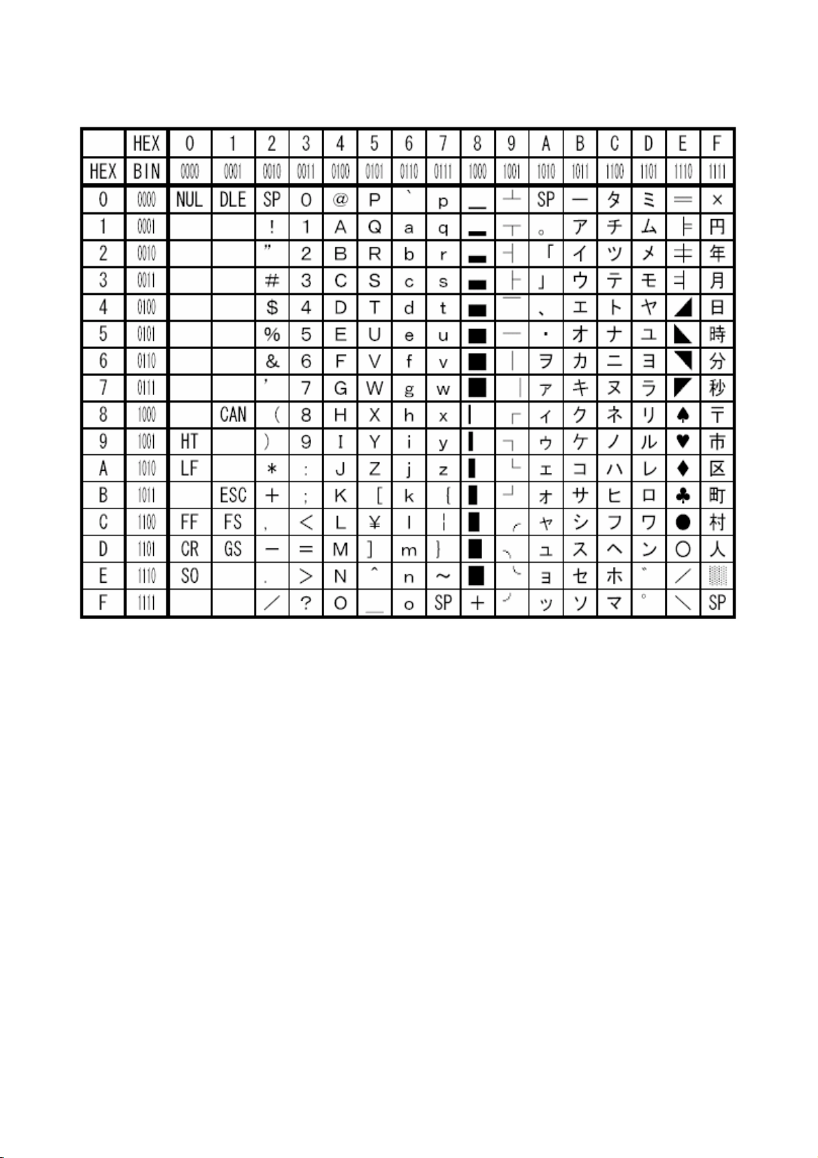
6. Character code table
6.1 Domestic character code table (International character set:: Japan)
*[SP] indicates "space".
*Printer operation cannot be guaranteed if the blank control code (codes below [1F]h) or undefined
code is transmitted to printer.
*This code table is for simplified symbols and does not present actual print result. There may be a
different case between code table and print result.
D-F0382 NP-266/366 Product specifications Ver.1.10
55
Page 60
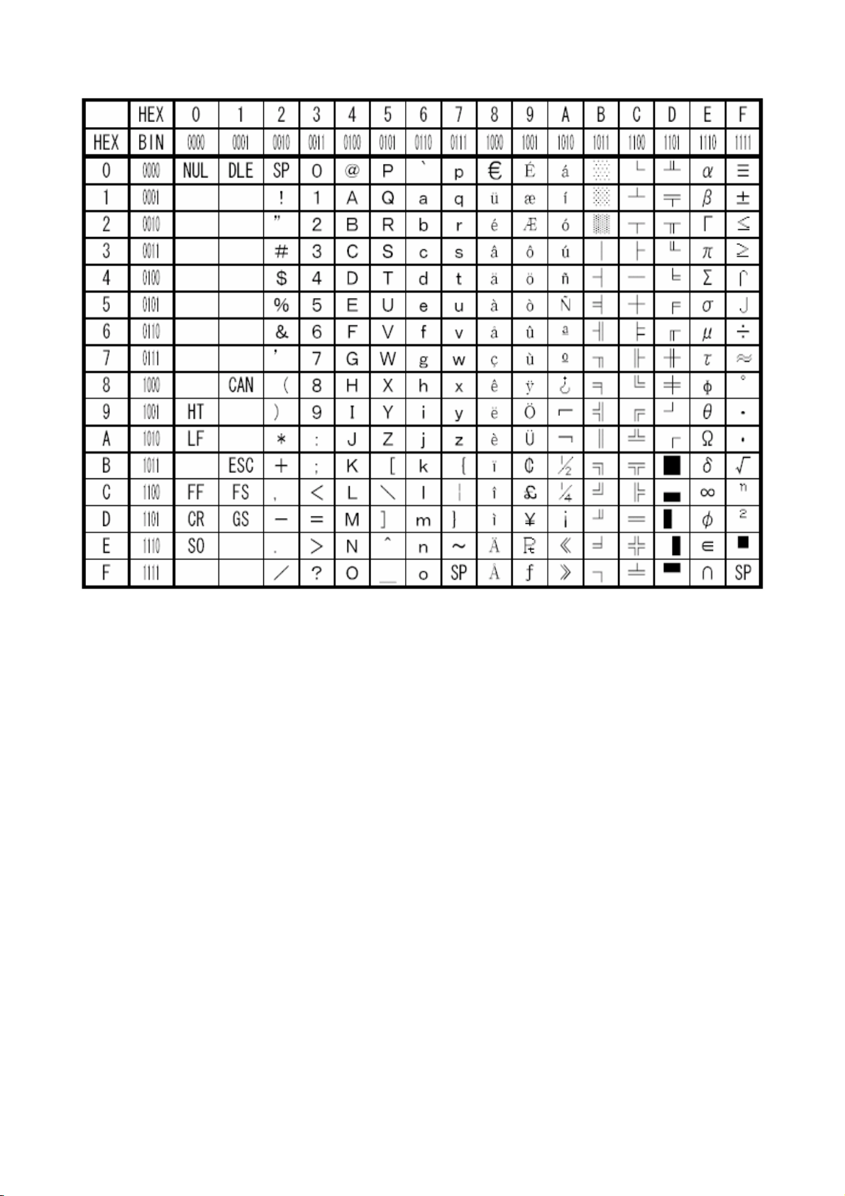
6.2 Overseas character code table (International character set: U.S.A)
*[SP] indicates "space".
*Printer operation cannot be guaranteed if the blank control code (codes below [1F]h) is transmitted to
printer.
*This code table is for simplified symbols and does not present actual print result. There may be a
different case between code table and print result.
D-F0382 NP-266/366 Product specifications Ver.1.10
56
Page 61
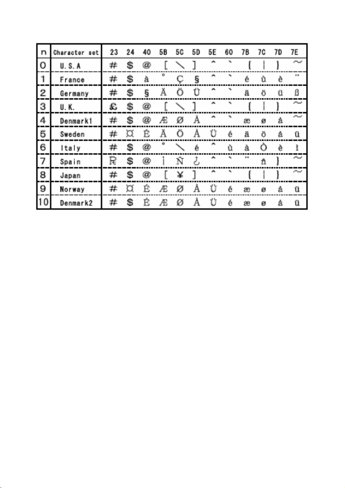
6.3 International character code table
*The code table is for simplified symbols and does not represent actual print result.
Accordingly the print result may be different from code table.
D-F0382 NP-266/366 Product specifications Ver.1.10
57
 Loading...