

Page 1

Provisional version
Specifications for
Compact module
Spec. No D-F0393
Product
Kiosk Printer
NP-211
Revision 0.01 2004.07.30 Provisional version
《Notice》 ・All features and specifications described are subject to change without notice.
D-F0393 NP-211 Product specifications Ver.0.01 Provisional
Page 2

Record of revision
Rev. No.
0.01 - New release Abe
(Provisional)
Page Item Change
Description
Approval PIC
2004.07.30
D-F0393 NP-211 Product specifications Ver.0.01 Provisional
Page 3

Read Carefully Before Using the Printer
Wrong handling of the printer may cause its performance declined and the product damaged. Please
read the notes below before handling.
1. Static discharge prevention must be made for installation and removal of the printer to protect IC
and other electrical parts. Connect it to the earth ground. It is also requested to remove the static
from body of the person before handling, especially, the input terminal.
2. Avoid excessive force to the input terminal for handling.
3. When any type of paper, other than specified in this manual, is used, it may cause deterioration
of the print quality and thermal head reliability.
Examples of troubles
1) Print quality deterioration by using low sensitivity paper.
2) Thermal head wears due to roughness of paper surface.
3) Sticking between heat receipt layer and thermal head, and vibration noise during printing.
4) Print ink disappears on low print durability paper.
5) Electrolyte corrosion on thermal head due to low quality of heat receipt layer.
4. Avoid printing with no paper loaded. It damages platen and thermal head, printer life will be
shorten.
5. Do not scrabble thermal head with sharp edge or something hard, or give impact. The heat
element may be damaged.
6. Set the power of printer off before connecting or removing connecters.
7. When printing in high speed under low temperature of high humidity environment, the paper may
be stained by moisture that appears from paper, or the printer may have condensation. Avoid
dew from dropping down to the thermal head that may cause electrolyte corrosion. Turn the
power off until any dew is removed.
8. The printer is not protected from water or dew formed. Do not water the printer or handle it with a
wet hand, which may cause damage to the printer due to short circuit, or heat or fire.
9. The printer is not protected from dust or dirt. If it is used at dusty place, the thermal head may be
damaged or paper feed is not operated properly.
10. When cooling the printer with a fan, avoid the printer’s paper outlet from locating fan’s air inlet. It
may cause mal-function of printer.
11. Reflection type of infrared ray sensors are used at some locations in the printer. Direct sun light
may cause mal-function of printer. Avoid from such a location for installation.
12. This printer does not support any operations caused by the commands or control commands not
specified in this manual.
Please use both hand to holding the printer.
13.
14. In order to prevent excess current, please put elemental device to external 24V power line
(Please refer to the power supply specification for the details), and also put fuse.
15. Please plug off the printer when you do not use the product for a long time. Please also insert
paper between the platen.
16. When paper jam occurred in the print head, please make sure to slowly remove the paper to
paper exit direction after head up status.
17. The product is designed to use with general electronic devices (Computer, PC, OA, others). This
is not designed and not guaranteed to use with extremely high quality, high reliability product or
product whose failure may danger human life (Atomic power control device, aerospace aircraft
devices, Transportation devices, Traffic signal devices, Ignition control devices, Medical devices,
other safety equipments: we call “Specific application” thereafter). Users take full responsibility
for using with such specific application.
18. The product uses part that includes GaAS (Gallium arsenide). Please do not break the product,
no chemical splitting ,otherwise it may harm human with such part broken pieces.
D-F0393 NP-211 Product specifications Ver.0.01 Provisional
Page 4

Table of Contents
1. Overview
1.1 Overview 1
1.2 Features 1
1.3 Configuration 2
2. Specifications
2.1 Basic specifications 3
2.2 Printing area and cut position 5
2.3 Electrical contitions 6
2.4 Reliability 6
2.5 Dimensions 7
3. Interface specifications
3.1 Serial interface (RS-232C compliance) 8
3.2 USB interface (V2.0 FULL SPEED compliance) 8
3.3 Connector signal details 9
4. Functions
4.1 Function setting 10
4.2 Self diagnostic print 12
4.3 Operation panel 12
4.4 Processing errors 13
4.5 Buffer full print 13
4.6 Auto loading 14
4.7 Partition drive 14
5. Control commands
5.1 Control command table 15
5.2 Printer driver 16
5.3 Control command details 17
6. Character code table
6.1 Domestic character code table 37
6.2 Overseas character code table 38
6.3 International character code table 38
6.4 Kanji code 39
D-F0393 NP-211 Product specifications Ver.0.01 Provisional
Page 5

1. Overview
1.1 Overview
The printer is categorized as following.
NP – 211- *
①
① Interface (Factory setting)
R: Serial (RS232C)
U: USB (V2.0 FULL SPEED)
D: Both Serial (RS232C) and USB (V.2.0 FULL SPEED)
1.2
Features
This module printer is designed on the basis of our long experience as a printer manufacturer.
Individual unit such as printer mechanism, controller board and auto-cutter is assembled in compact
with our reliable design concept.
Simple integration to the system requiring only power and data supplies, that contributes to the
short development time and improvement of product reliability.
1) Important areas such as paper entrance and auto-cutter guide are designed professionally on
the basis of our long experience as a printer manufacturer.
2) Small, compact and light weight. Easy to integrate into various kinds of system.
3) Short development time.
4) High quality of printing
5) Either serial or USB interface are available.
6) Various 1-D barcode symbols are available.
7) Various kinds of application are available.
8) Windows drivers (Windows95/98/NT4.0/2000/XP) are available.
9) Easy to write/rewrite F/W by using flash memory. Also, 3 patterns of registration are
available with Fixed bit image.
D-F0393 NP-211 Product specifications Ver.0.01 Provisional
1
Page 6

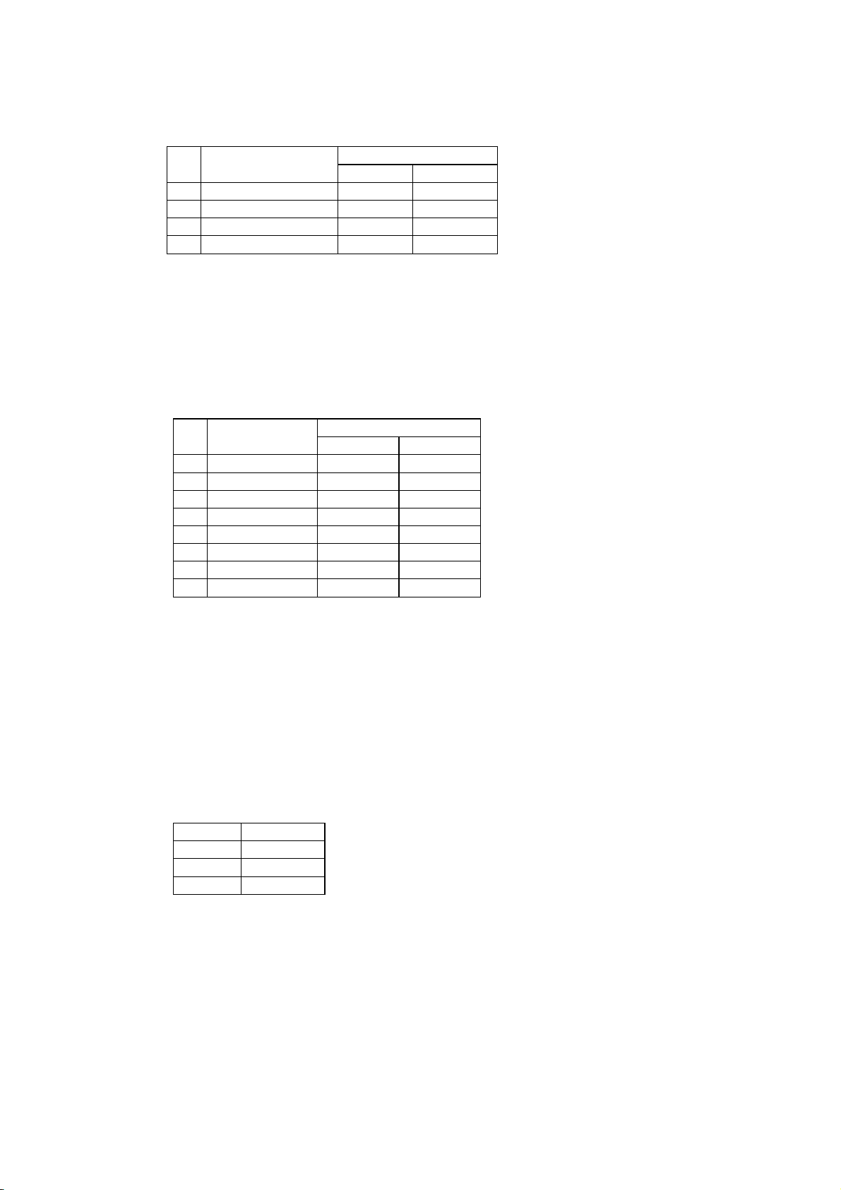
1.3 Configuration (Under review)
The printer consists of the following components.
No. Description Specification Part No. Q’ty
1 Printer unit NP-211-* - 1
2 Thermal Paper TF50KS-E2DW58xØ 30(Inner Ø12) 24-X129 1
3
Jack socket ※1
※1 It is attached in R type and D type. Jack socket of the serial connector is for an inch screw.
Please use the attached M2.6 socket if necessary.
Options
17L-003A3 (M2.6 x 0.45) 06-F102 2
No. Description Specification Part No. Q’ty
1 Near empty sensor Factory option - (1)
2 AC adaptor 100V 91ADJ 18-R035 (1)
3 AC adaptor 120V 91ADU 18-R036 (1)
4 AC adaptor 230V 91ADE 18-R037 (1)
5 AC code set JPN 1.5 m 30-353A (1)
6 AC code set UL (3P) 1.5 m 30-354A (1)
7 AC code set EU (Flat 2P) 1.5 m 30-355A (1)
D-F0393 NP-211 Product specifications Ver.0.01 Provisional
2
Page 7
2. Specifications
2.1 Basic specifications
No. Items Specifications
1 Print specs. 1. Print method Line thermal dot
2. Total dots / line 384 dots
3. Dot density 8 dots / mm (203dpi)
4. Print width 48mm
5. Print speed (Max.) Max.50 mm / sec
Condition Head temp. more than 35 ℃/ 64 dots
Except for communication time
6. Print digits
Font A (12×24) 32 digits
Font B (9×17) 42 digits
Kanji (24 x 24) 16digits
7. Space between Adjustable by command setting
characters (Default figures)
Font A 0 mm
Font B 0 mm
Kanji 0 mm
8. Line feed pitch 0.125 mm
2 Character 1. Character size
specs. Font A (12×24) 1.50×3.00 mm
Font B (9×17) 1.13×2.13 mm
Kanji(24 x 24) 3.00x3.00mm
2. Character types
Japanese JIS C 6226 (Full size)
Katakana character set (Half size)
Extended Graphic character set (Half size)
International character (Half size)
3.
Character modification
Double width
Vertical double
Quadruple
Bold
Double strike
Inverted
90°clockwise rotation
Underline
4. Line spacing (Default) 4.25 mm (1/6 inch)
D-F0393 NP-211 Product specifications Ver.0.01 Provisional
3
Page 8
No. Items Specifications
3 Print mode ANK mode
Bit image mode
Barcode mode
4 Barcode 1. 1-D symbology UPC-A
specs UPC-E
EAN-13 (JAN-13)
EAN-8 (JAN-8)
CODE39
ITF
CODABAR
CODE128
5 Interface 1. Serial RS232c compliant
2. USB V2.0 FULL SPEED
6 cutter Tier bar
7 Paper specs. 1. Paper width 58.0 mm
2. Max. diameter Ø70 mm
The following core to be used.
3. Core diameter Inner Ø12mm / Outer Ø18mm
No glue at the end of the roll
4. Papers recommended TF50KS-E2D (Nihon Seishi)
TF77KS-E2 (Nihon Seishi)
TL69KS-HG76 (Nihon Seishi)
8 Receiving Approx. 5K bytes
buffer
9 Environment 1: Operating Temp. 5- 45℃, Humidity 35 – 85%RH, No- condensation.
2: Storage Temp. -10 - 60℃ Humidity 35-90%RH excluding paper
discoloration.
3: Enviroment in use General Office Room.
10 Appearance 1: External dimension 84.0 (W) x 115.0(D) x 77.5(H) mm
2: Weight Approx. 400 g
D-F0393 NP-211 Product specifications Ver.0.01 Provisional
4
Page 9
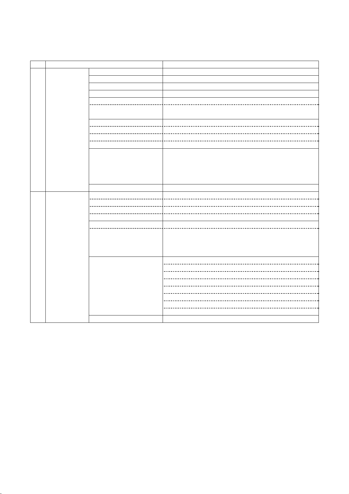
2.2 Printing area and cut position
Cut Position
Tier bar~Head
position
20±1.0mm
Approx.5mm(※) 1dot 2dots 384dots
Feed direction
0.125mm
0.125mm
48±0.2mm
5±1.0mm 5±1.0mm
58 mm
0
-1
(※)There is a line at the approx. 5 mm from print position when cut.
D-F0393 NP-211 Product specifications Ver.0.01 Provisional
5
Page 10

2.3 Electrical conditions
1) Operating voltage : DC 8V – 13V
2) Current consumption …. Under review
Current consumption
Printing average of 25% Max. Approx. ** A
Printing average of 100% Max. Approx. ** A
*1: A sufficient volume of power supply is required to maintain print quality due to high peak current that
may run according to printing.
*2: If power supply cable is excessively long, the operation may become unstable. Cable should be
made as short as possible. If not available, connect cables near the printer and place an electrolysis
condenser of 2200µ between power supply and ground. Voltage resistance should be higher than 35V.
*3: For preventing from static electric discharge, make sure to connect FG wire.
2.4 Reliability
1) Head life
Pulse : More than 100 million pulses (with 25% rated energy )
Wear distance : More than 50 km
(with recommended paper, normal temp. humidity)
2) Operation environment : Temperature 5 – 45℃, no condensation
Humidity 35 - 85%RH
3) Storage environment : Temperature -10 – 60℃
Humidity 35 - 90%RH
4) Safety regulation
CE marking (To be certified)
UL60950-1 (To be certified)
5) EMC
EMI : EN55022 (To be certified)
EMS : EN55024 (To be certified)
VCCI : Class A (To be certified)
FCC : Class A (To be certified)
6) USB compliant test (To be certified)
D-F0393 NP-211 Product specifications Ver.0.01 Provisional
6
Page 11
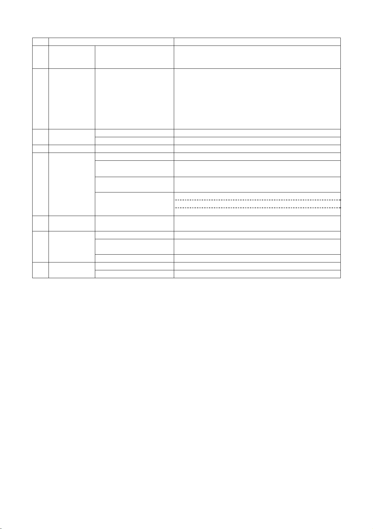
2.5 Dimensions
NEAR ENPTY OPTION
90
77.5
84.0
75.6
42.0
5
1
φ60
MAX DIA 70mm
FEEDENTRYALMPO
115.0
9.3
2.9
PAPER EXIT
D-F0393 NP-211 Product specifications Ver.0.01 Provisional
7
Page 12

3. Interface specifications
3.1 Serial interface (RS-232C compliance)
1) Synchronization : Asynchronous
2) Transmission speed: 9600, 19200, 38400, 115200bps (user selectable)
3) A word consists of
Start bit : 1bit
Data bit : 7 or 8 bit (user selectable)
Parity bit : odd, even or no parity (user selectable)
Stop bit : more than 1 bit
4) Signal polarity
RS-232C
Mark = Logic “1” (-3V ~ -12V)
Space = Logic “0” (+3V ~ +12V)
5) Receive data (RD signal)
Mark = 1
Space = 0
6) Reception control (DTR signal)
Mark = Impossible to receive the data
Space = Possible to receive the data
7) Transmission control (CTS signal)
Mark = Impossible to transmit the data
Space = Possible to transmit the data
8)Transmission control (TD signal)
<< DC1 >> [11] h code, XON :Possible to receive the data
<< DC3 >> [13] h code, XOFF:Impossible to receive the data
3.2 USB interface (V2.0 FULL SPEED compliance)
1) Version : V2.0 FULL SPEED compliance (12Mbps)
2) Port : Upstream port (Mini-B 5P)
3) Power : Self powered
D-F0393 NP-211 Product specifications Ver.0.01 Provisional
8
Page 13
3.3 Connector signal table
1)Power Input connector
Printer side adaptor jack:MOJ-D14(Iizuka electronic)equivalent
Printer side adaptor plug:PJ-2(Sato Parts)equivalent
Pin No. Signal In/Output Function Remark
+ VH Input PowerDC+8V - 13V
- GND
-
PowerGND
※A sufficient volume of power supply is required to maintain print quality due to high peak
current that may run according to printing.
※If power supply cable is excessively long, the operation may become unstable. Cable
should be made as short as possible. If not available, connect cables near the printer and
place an electrolysis condenser of 2200µ between power supply and ground. Voltage
resistance should be higher than 35V.
2)USB data Signal Input Connector (U type, D type)
Printer side connector:Mini-B 5P TCX0101-110100(Hosiden) or equivalent
Mating connector:Mini-B 5Por equivalent
Pin No. Signal In/Output Function Remark
1 VBUS Input Power line Non-twist power supply line
2 D- In/Output Data line Twist pair signal line
3 D+ In/Output Data line Twist pair signal line
4 N.C
5 GND
Shell Shield
-
-
-
GND Non-twist power supply line
FG Frame GND
※Use USB cable which conforms to the standard (FULL SPEED)
3)Serial data signal input connecter (R type, D type)
Printer side connecter: JEC-9S (JST) equivalent
Mating connecter: JEC-9P (JST) equivalent
Pin No. Signal In/Output Function Remark
2 RXD Input Serial receive data
3 TXD Output Serial transmit data
4 DTR Output Data transmit permit signal Connect to No.7
5 GND - GND for signal
7 DTR Output Data transmit permit signal Connect to No.4
8 CTS Input Transmit permit signal
1,6,9 N.C -
D-F0393 NP-211 Product specifications Ver.0.01 Provisional
9
Page 14
4. Functions
4.1 Function setting
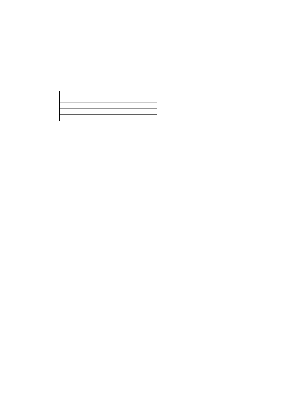
4.1.1 Memory switch S1
Function O N OFF
Factory setting
R-type
U-type D-type
S1-1 Interface Serial USB O N OFF OFF
S1-2 OFF OFF OFF
S1-3
Baud rate
Refer to the following
table
OFF OFF OFF
S1-4 Parity check Yes No OFF OFF OFF
S1-5 Parity bit Odd Even OFF OFF OFF
S1-6 Data bit 7 bit 8 bit OFF OFF OFF
S1-7 Flow control XON/XOFF DTR/DSR OFF OFF OFF
S1-8 Reserved OFF OFF OFF
Baud rate
9600bps 19200bps 38400bps 115200bps
S1-2 OFF OFF O N O N
S1-3 OFF O N OFF O N
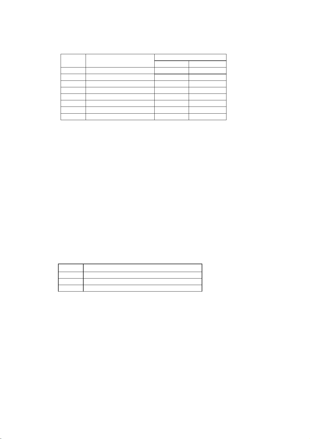
4.1.2 Memory switch S2
Function O N OFF
Factory setting
R-type
U-type D-type
S2-1 Character set Overseas Domestic OFF OFF OFF
S2-2 Japanese Kanji Shift JIS JIS OFF OFF OFF
S2-3 Reserved OFF OFF OFF
S2-4 Print density Thick Standard OFF OFF OFF
S2-5 HEX DUMP
HEX
DUMP
Normal OFF OFF OFF
S2-6 Not defined OFF OFF OFF
S2-7 Not defined OFF OFF OFF
S2-8 Not defied OFF OFF OFF
4.1.3 Rewriting Flash ROM
Please do the following procedure to rewrite a program in a Flash ROM. Send the program from
the host, and turn off the powe after confirming the ALM LED turns off completely.
1) Switch operation when rewriting the firmware program
Head up lever: Head up
Feed switch: ON (press)
Entry swich: OFF
Turn the power on, the ALM LED start flashing slowly, then release the feed switch.
2) Switch operation when rewriting boot program
Head up lever: Head up
Feed switch: ON (press)
Entry swich: ON (press)
Turn the power on, the ALM LED start flashing slowly, then release the feed and enrty switch.
D-F0393 NP-211 Product specifications Ver.0.01 Provisional
10
Page 15

4.1.4 Setting of Memory switch
For setting or changing Memory switch, first load a roll of paper, then follow the below
procedure for mode setting (1) and switch setting (2).
After completion of the settings, it automatically operate software reset. Please confirm the
setting result by self print.
1)Mode setting
Head up lever: Head down
Feed switch: ON (press)
Entry swich: ON (press)
Then turn the power on, it print "** MEMORY SW SETTING MODE **". This is the
setting mode. You may release the Feed and Entry switch.
2)Memory switch setting
Setting starts from Memory switch S1-1 to S1-8, and from S2-1 to S2-8.
After change to the SETTING MODE, the LED start flashing.
・Press Feed switch when the LED is on, memory switch setting is on, and the result will
be printed.
・Press Feed switch when the LED is off, memory switch setting is off, and the result will
be printed.
Please continue such setting 16 times to complete all the settings.
If you would like to cancel the setting in the middle, please head up and press the feed
switch once, then head down.
If you change the setting when head up state, such change is not effective.
D-F0393 NP-211 Product specifications Ver.0.01 Provisional
11
Page 16

4.2 Self diagnostic print
1) By performing self-diagnostic print following items are checked.
a) Proper function of control circuitry
b) Proper function of printer mechanism
c) Print quality
d) Control F/W version
e) Memory switch setting status
f) Correct function of paper out sensor
g) Head wide and head rank (automatically detected)
2) Start and end of self diagnostic print
Set the power on while pressing the FEED switch and release the FEED switch after the printer
mechanism activates to start self-printing.
The self diagnostic print automatically ends when a preset number of characters are finished
printing. While printing, the printer is in Off-line mode.
4.3 Operation panel
Operation switch is attached at the side of the printer.
1)PO (green) [Power lamp]
It is on when power is supplied to printer.
2)ALM(red) [Alarm lamp]
It will be on or flash when printer is in an error status.
I will be flash/on/ off when rewriting to the Flash ROM
3)ENTRY [Setting switch]
It is the switch when change the setting of memory switch.
It is used when rewriting to the Flash ROM.
4)FEED [Feed switch]
It is a feed switch for paper feed.
It is used when the memory switch setting mode, memory switch setting,
rewriting to the Flash memory mode set, and self print.
D-F0393 NP-211 Product specifications Ver.0.01 Provisional
12
Page 17

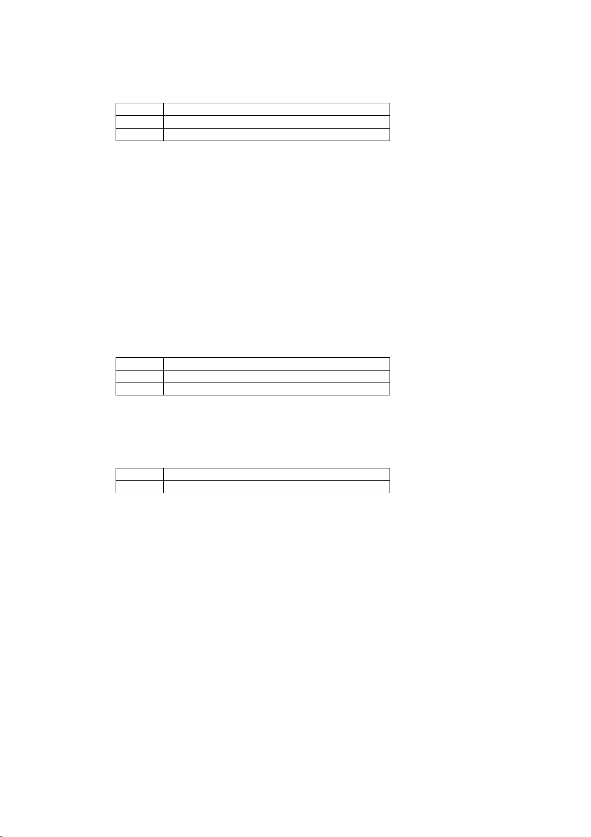
4.4 Processing errors
1) Error detection details
Name Status
232C
status
ALM status Removal
Comm. 232C Comm. error - - Align comm.condition
error Parity
Overrun
Flaming
Data “?” print
Head up Head up 1bit 1 On Head up lever down
Paper end No paper 2bit 1 On Load paper
Head temp
Over 80°C
high
3bit 1 Flash Return normal
with 60°C
Cutter cover Cutter cover open 5bit 1 Flash Cutter cover close
open
When the above errors are detected except transmission error and paper near end error, printer
stops all operations and outputs error signal.
In the case of serial interface:
Error bit in the status information is set to “ON”.
ALM pattern Printer status
1
0
1
0
1
0
0
1
0
0.2sec
0.2sec 1.0sec
0.1sec
2.2sec
0.1secc
2.2sec
Normal
Possible to print
Paper out
Head up
F/W rewrite mode
Head temp. high (over 80 ℃) 1
Head connection error
Cutter cover error
2) Return to normal status from error statuses
Remove causes of error statuses and turn the power on again or input the /INIT signal to
return to normal. When this process is activated, at the time of power switch turned off, the
printer will be initialized, so that settings are required again.
If data remains in the buffer, attention should be paid
4.5 Buffer full print
If there remains data in the buffer after one line of data is received, printer automatically prints
preceding data. The volume of buffer full data varies depending on ASCII characters or bit
images.
D-F0393 NP-211 Product specifications Ver.0.01 Provisional
13
Page 18

4.6 Auto loading
If you insert paper to the printer mechanism, paper will be automatically loaded. Please make sure
to insert the paper propaerly so the sensor will detect the paper.
4.7 Partition drive – under review
D-F0393 NP-211 Product specifications Ver.0.01 Provisional
14
Page 19
5. Control commands
5.1 Control command table
Control codes Functions Pages
1 HT Horizontal tab 17
2 CR Carriage return 17
3 LF Print and line feed 17
4 FF Page feed 17
5 ESC C n Page length set for n lines 17
6 ESC SP n Character right space set 17
7 ESC ! n Print mode overall set 18
8 ESC % n Down load character set/reset 18
9 ESC & s n m a Dn Down load character definition 18
10 ESC * m n1 n2 Dn Bit image mode set 21
11 ESC – n Underline set/rest 23
12 ESC 2 1/6 inches line feed set 23
13 ESC 3 n Smallest line feed pitch set 23
14 ESC @ Initialize printer 23
15 ESC D n1 n2 --- NUL Set horizontal tab position 23
16 ESC E n Bold print set/reset 24
17 ESC G n Double strike print set/reset 24
18 ESC J n Print and smallest pitch line feed 24
19 ESC R n Select international character 24
20 ESC c 5 n Feed switch enable/disable 25
21 ESC d n Print and n line feed 25
22 ESC t n Select character code table 25
23 ESC v Send printer status 25
24 ESC { n Inverted character set/reset 26
25 ESC V n
26 ESC $ n1 n2 Absolute position set 26
27
ESC \ n1 n2
28 GS k n Dn NUL Barcode print 27
29 GS w n Barcode width select 27
30 GS h n Barcode height select 27
31 GS H n HRI character print position select 27
32 GS f n HRI character style select 28
33 GS * n1 n2 Dn Download bit image define 28
34 GS / m Download bit image print 29
35 ESC = n Data input control 29
36 ESC a n Position align 29
37 GS T n Register Fixed bit image 30
38 GS P n Print Fixed bit image 30
39 GS d Dn FirmwareDownload 30
40 DC1 Software reset 30
41 GS ~ n Print density set 30
Character 90° clockwise rotation set/reset
26
Relative position set 26
D-F0393 NP-211 Product specifications Ver.0.01 Provisional
15
Page 20
Control codes Functions Pages
42 FS ! n Japanese Kanji overall print mode setting 31
43 FS & Japanese Kanji mode setting 31
44 FS – n Japanese Kanji underline set / reset 31
45 FS . Japanese Kanji mode reset 31
46 FS C n Japanese Kanji code select 32
47 FS S n1 n2 Japanese Kanji space setting 32
48 FS W n Japanese Kanji Double height and width set
/ reset
49 ESC s n Sending the printer information 32
50 GS : Macro definition, start and end 33
51
GS ^ n1 n2 n3
52 GS B n
53 ESC b n1 n2 n3 Dn Raster bit image 34
54 FS 2 a1 a2 Dn Definition additional character 35
55 ESC B n Back feed 36
Macro execution 33
Black and white reverse print set / reset
32
33
5.2 Printer driver
Please apply the driver stated below for using NP-211 under Windows environment. Refer to the
User’s Manual for a driver.
1) Windows 95/98: NII printer driver Windows 95/98, Version 1.00
2) Windows NT4.0: NII printer driver Windows NT4.0, Version 1.00
3) Windows 2000/XP: NII printer driver Windows 2000/XP, Version 1.00
4) Windows 2000/XP: NII printer driver Windows 2000/XP for USB, Version 1.00
D-F0393 NP-211 Product specifications Ver.0.01 Provisional
16
Page 21

5.3 Control command details
1) Horizontal tab : << HT >>
Code : [09] h
Shift the print position to the next horizontal tab position
* Horizontal tab position is set by [horizontal tab set] command.
* The default of horizontal tab position is every 8th character (9th digit,
17th digit, 25th digit) in font A.
* If the next tab position is not set, this command is ignored.
2) Carriage return : << CR >>
Code : [0D] h
This command is ignored.
3) Line feed : << LF >>
Code : [0A] h
Prints data stored in the input buffer and executes line feed according to data
of feed pitch.
4) Page feed : << FF >>
Code : [0C] h
* Prints data in the print line buffer and executes page feed to the head of next page
according to the page length in the setting.
5) “n” line page length setting : << ESC C n >>
Code : [1B] h + [43] h +n * [01≤n≤FF] h
Sets a page length for “n” lines with current line feed pitch.
* Position is set to the head of page
* Line pitch change after setting will not change page length.
* Default value for “n” is [42] h for 66 lines.
* If printer is initialized, the head of page is also initialized.
6) Setting right space of a character : << ESC SP n >>
Code : [1B] h + [20] h + n * [00≤n≤20] h
Sets the right space of a character by unit of dot (1/203 of an inch). In the case of
double width mode, the space will be doubled. The default value of “n” is [00] h.
D-F0393 NP-211 Product specifications Ver.0.01 Provisional
17
Page 22
7) Overall print mode setting : << ESC ! n >>
Code : [1B] h + [21] h + n * [00≤n≤FF] h
Sets print mode. “n” has following meanings
Bit Function
Values
0 1
0 Character font Font A Font B
1 Undefined - 2 Undefined - 3 Bold Reset Set
4 Double height Reset Set
5 Double width Reset Set
6 Undefined - 7 Underline Reset Set
* If double height and double width are set at the same time quadruple character will be formed.
* All of the printed characters will be underlined except for the 90° rotated characters and spaces
created by horizontal tab.
* Underline width is determined by the value set in [Underline set/reset] section.
The default value is “1”.
* Only Bold is effective in Kanji mode.
* Different sizes of character mixed such as double width and normal size can be printed.
* The default value of “n” is [00] h.
8) Download characters set/reset : << ESC % n >>
Code : [1B] h + [25] h + n * [00≤n≤FF]h
Setting or resetting the characters to be downloaded.
* Only LSB (b0) is valid for “n” value. LSB (b0) has the following meanings.
b0 Function
0 Resets download chraracter
1 Sets download chraracter
* Default value is “n” = [00] h
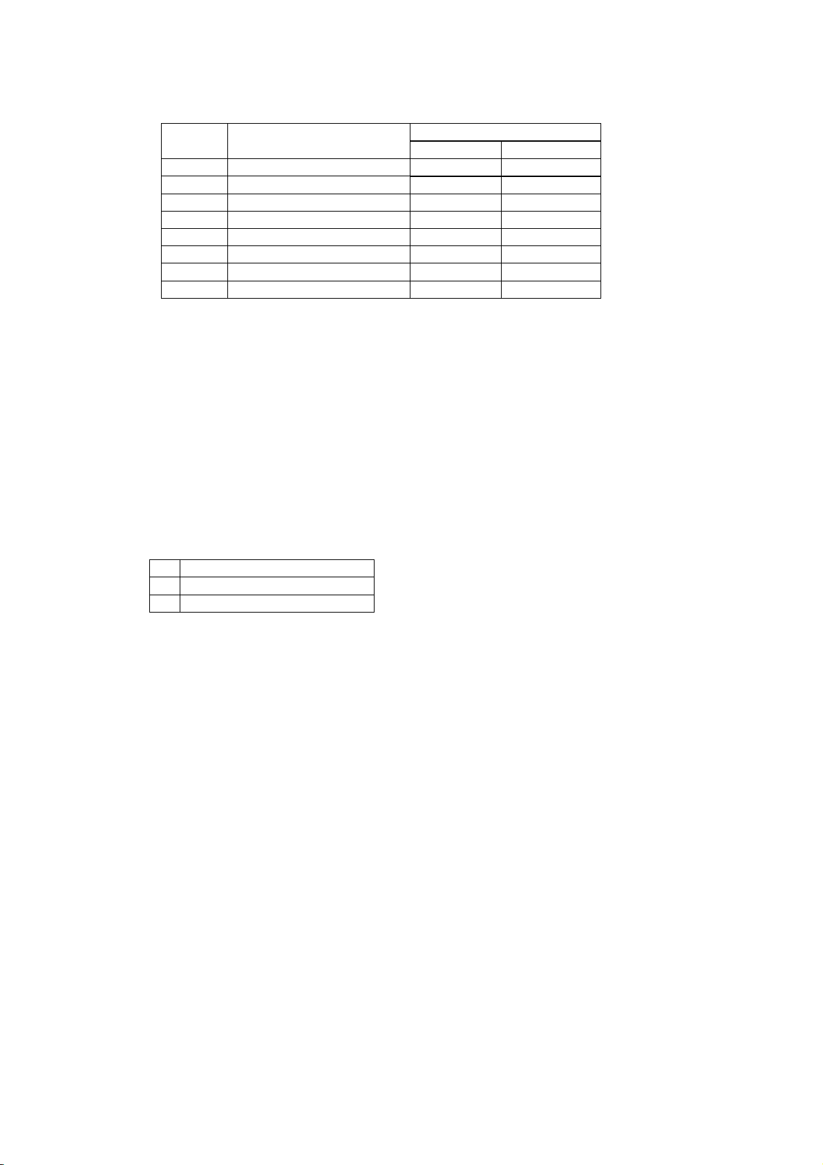
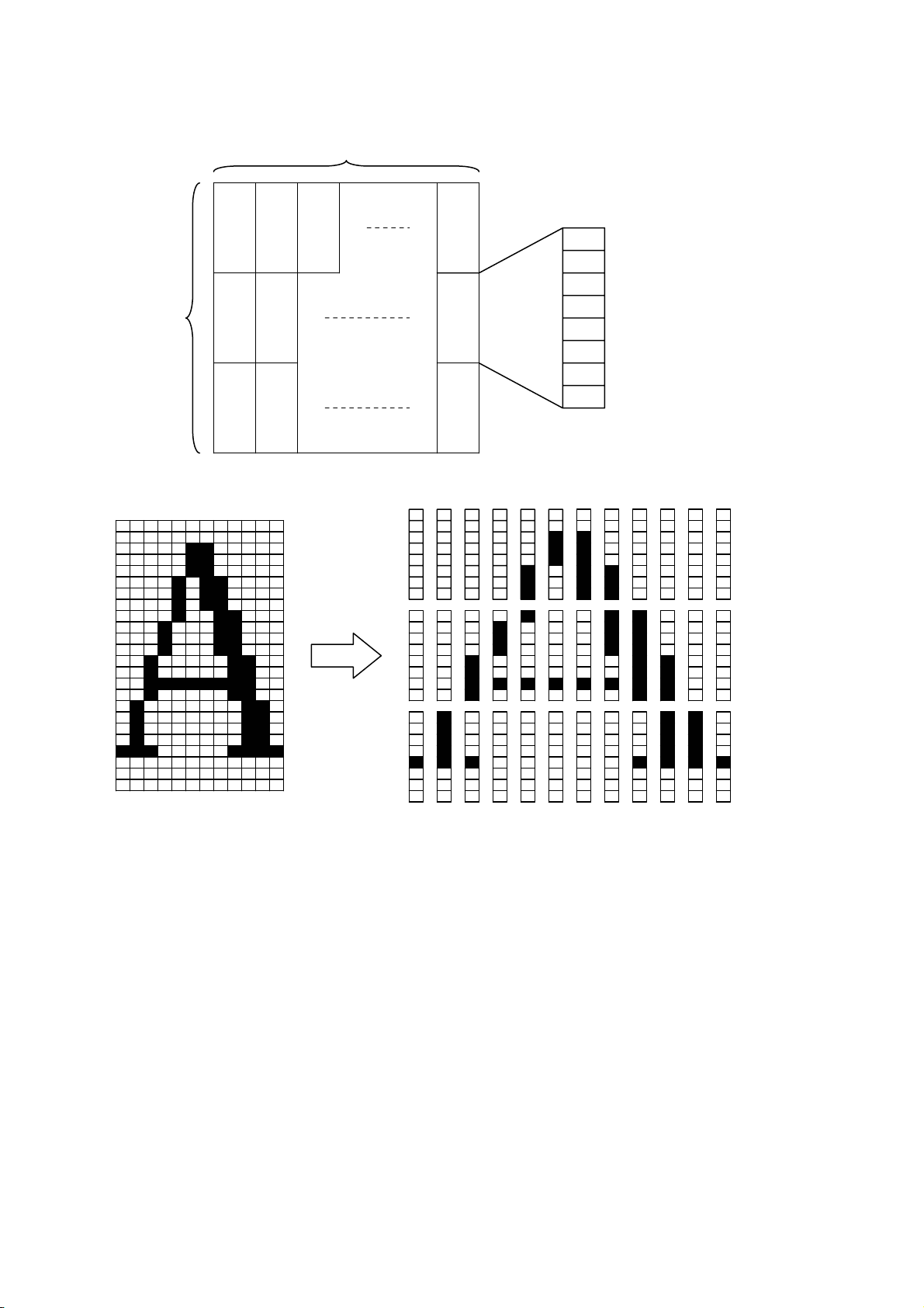
9) Definition of download character :<< ESC & s n m a Dn >>
Code : [1B] h + [26] h + s + n + m + a + Dn
* [s = 03 ] h
* [20≤n≤7E ] h
* [20≤m≤7E ] h
* font A [ 01≤a≤0C ] h
* font B [ 01≤a≤09 ] h
Definition of download character( such as alpha numeric).
* “s” indicates a number of bytes in a vertical direction and “a” is a number of dots in
horizontal direction.
* “n” indicates the start character code, and “m” means the end character code. If only 1
character should be defined, then n = m.
* Definable characters are from <20>h to <7E>h in ASCII code (95 characters).
* “Dn” indicates the data to be defined. It indicates the “a” dots pattern from the left.
Remaining area on the right of a character is filled with spaces.
* Once a download character is defined, it remains valid until the download character is
redefined, printer is initialized, or the power is turned off.
* Only area specified will be reset.
D-F0393 NP-211 Product specifications Ver.0.01 Provisional
18
Page 23
< Reference >
In the case of Font A
P1
12dots
P4
P7 P34
MSB
24dots
P2
P3
P5
P6
P35
P36
LSB
P1= [00] h, P4= [00] h, P7= [00] h, P10= [00] h, …
P2= [00] h, P5= [00] h, P8= [0F] h, P11= [72] h, …
P3= [08] h, P6= [F8] h, P9= [08] h, P12= [00] h, …
D-F0393 NP-211 Product specifications Ver.0.01 Provisional
19
Page 24
< Reference >
In the case of Font B
9dots
MSB
17dots
P4
P5
P7
P25
P26
LSB
MSB
P1
P2
P27P6 P3
LSB
P1= [40] h, P4= [7F] h, P7= [41] h, P10= [41] h, …
P2= [04] h, P5= [FC] h, P8= [04] h, P11= [04] h, …
P3= [00] h, P6= [00] h, P9= [00] h, P12= [00] h, …
D-F0393 NP-211 Product specifications Ver.0.01 Provisional
20
Page 25
10) Bit image mode set : << ESC * m n1 n2 Dn >>
Code: [1B] h + [2A] h + m + n1 + n2 + Dn * [m = please refer to table below] h
* [00≤n1≤FF] h
* [00≤n2≤01] h
Data is printed in bit image by following the bit image mode specified by “m”.
* Print total dots divided by 256, quotient is n2 and remainder is n1.
* Total dots in bit image mode are n1 + (256 x n2).
* If the bit image input data exceeds specified position, the exceeded data will be disregarded.
* Bit image data (Dn) interprets bit 1 as print and bit 0 as not print.
* Bit image mode is as indicated below.
Vertical direction Horizontal direction
m
(hex)
00
01
20
21,23
Bit image
mode
8 dots single
density
8 dots double
density
24 dots single
density
24 dots
double density
Dot
quantiy
Dot
density
Dot density
8 67DPI 101DPI 192
8 67DPI 203DPI 384
24 203DPI 101DPI 192
24 203DPI 203DPI 384
Maximum dot
number
D-F0393 NP-211 Product specifications Ver.0.01 Provisional
21
Page 26

< Relationship between bit image data and printed dots >
8dots bit image
MSB
D1 D2 D3
D1 D2 D3
LSB
Data
=1dot
Single Double
24 dots bit image
D4 D7 MSB
D1
D1 D2 D3 D7 D8 D9
D4
D5 D6
D2
D5
D8
D3
D6 D9
LSB
Data
=1dot
Single Double
D-F0393 NP-211 Product specifications Ver.0.01 Provisional
22
Page 27

11) Underline set/reset : << ESC - n >>
Code : [1B] h + [2D] h + n * [00≤ n ≤02] h
Sets and resets the underline
* Underline is valid for all characters except for the area skipped by horizontal tab.
* Also Underline is not valid for 90° rotated character.
* Underline is verified with n value as shown bellow.
n(hex) Type of underlines
00 Reset underline
01 Set one dot underline
02 Set two dot underline
* Default value is “n” = [00] h
12) 1/6th of an inch line feed pitch : << ESC 2 >>
Code : [1B] h + [32] h
Sets one line feed to 1/6th of an inch.
13) Sets smallest pitch line feed : << ESC 3 n >>
Code : [1B] h + [33] h + n * [00≤ n ≤FF] h
Sets a line feed pitch to n/203rd of an inch.
* Despite of height set by value, the same space with character height is sent by line feed.
* The default value of n is [22] h
* If n = [00] h is set, printer will not feed by pressing FEED button.
14) Printer initialization : << ESC @ >>
Code : [1B] h + [40] h
Clears the data stored in the print buffer and resets each setting to default values.
* It does not clear the data stored in the internal receive buffer.
* It is stored in the internal receive buffer and activated in sequential.
15) Horizontal tab position set : << ESC D n1 n2 --- NUL >>
Code : [1B] h + [44] h + n1+ n2 + --- + [00] h *[00≤ n ≤FF] h
Sets the horizontal tab position
* “n” indicates the digits number from the left. In this case, n = tab position - 1.
* Tab position is set at the location of character width x n from the beginning of a
line. The character width in this case includes character right space. When double
width function is set, then the width becomes double of ordinary character.
* Maximum number of tab positions is 32. If setting exceeds 32, then
the exceeded values are neglected.
* << ESC D NUL >> clears all tab positions being set. After the tab is cleared,
horizontal tab will be ignored.
* Default value is set at every 8 characters of font A (at 9
th, 17th, 25
th
digit).
D-F0393 NP-211 Product specifications Ver.0.01 Provisional
23
Page 28

16) Bold print set/reset :<< ESC E n >>
Code : [1B] h + [45] h + n * [00≤ n ≤FF] h
Sets and resets the bold print
* “n” is only valid for LSB(b0)
* LSB (b0) is defined as following.
b0 Values
0 Resets bold print
1 Sets the bold print
* Print result may be deformed in case black and white reverse at bold print.
* Bold print and double strike results in the same on this printer.
* The default value of “n” is [00]h.
17) Double strike set/reset :<< ESC G n >>
Code : [1B] h + [47] h + n * [00≤n≤FF] h
Sets and resets the double strike function
* “n” is only valid for LSB (b0)
* Control by “n” is explained as following.
b0 Description
0 Resets double strike
1 Sets double strike
* Double strike and bold print result in the same on this printer.
* The default value of “n” is [00] h.
18) Print and smallest pitch line feed :<< ESC J n >>
Code : [1B] h + [4A] h + n * [00≤n≤FF] h
Prints the data in the print line buffer and feeds the paper by n/203rd of an inch.
* The height of character for a line is always sent by line feed. If the value of height is set
by “n” below the height of character, the same space with character height is sent by
line feed.
* Beginning of a line is a print start position.
19) International character select :<< ESC R n >>
Code : [1B] h + [52] h + n * [00≤n≤0A] h
Selects the international characters.
* The values of “n” have following meanings
n(Hex) Character sets
00 U.S.A.
01 France
02 Germany
03 England
04 Denmark 1
05 Sweden
06 Italy
07 Spain
08 Japan
09 Norway
0A Denmark 2
* Default value of “n” is [08] h.
D-F0393 NP-211 Product specifications Ver.0.01 Provisional
24
Page 29

20) FEED switch enable/disable :<< ESC c 5 n >>
Code : [1B] h + [63] h + [35] h + n * [00≤n≤FF] h
Changes the FEED switch valid or invalid.
* “n” is only valid for LSB (b0)
* “n” bit has a following meanings
b0 Description
0 enable FEED switch
1 disable FEED switch
* Default value of “n” is [00] h.
21) Print and “n” line feed :<< ESC d n >>
Code : [1B] h + [64] h + n * [00≤n≤FF] h
Prints the data in the print buffer and feeds paper by “n” lines.
* Beginning of a line is a print start position.
* If there is print data remained, line feed is activated for the same height of character.
22) Character code table select :<< ESC t n >>
Code : [1B] h + [74] h + n * [00≤n≤01] h
* “n” value has following meaning.
n(Hex) character code table
00 Overseas character code table
01 Domestic character code table
* The default value of “n” is set with memory switch (S2-1).
23) Printer status transmission :<< ESC v >>
Code : [1B] h + [76] h
Sends current printer status
* Status to be transmitted consist of 1 byte and the content is explained in the chart below.
* Regarding DTR/DSR control, only one byte is transmitted after confirmation that the
host is able to receive data, that is DSR signal is in SPACE status. For XON/OFF
control, one byte is transmitted without confirmation of DSR signal status.
* For DTR/DSR control, if host is not in a receivable status, it waits until host can receive
data.
bit Functions
0 1
Value
0 Reserved
1 platen open normal head open
2 paper end paper present no paper
3 head temp. abnormal normal Temp. abnormal
4 Undefined
5 Cutter cover open normal Cutter cover open
6 Undefined
7 Undefined
* Make sure that command is issued before transmission of print data.
(commands are stored in the input buffer and executed sequentially)
* Reception is available except in the buffer full status.
* The commands above are valid only for serial interface.
D-F0393 NP-211 Product specifications Ver.0.01 Provisional
25
Page 30

24) Inverted character set and reset :<< ESC { n >>
Code : [1B] h + [7B] h + n * [00≤n≤FF] h
Sets or resets the inverted character function
* “n” is only valid for the LSB (b0)
* LSB (b0) has the following meaning
b0 Description
0 resets inverted character
1 sets inverted character
* The command is only valid when it is assigned at the beginning of a line.
* The default value of n is [00] h.
25) 90° clockwise rotated character set and reset :<< ESC V n >>
Code : [1B] h + [56] h + n * [00≤n≤01] h
Sets and resets 90° clockwise rotated character.
* Underline cannot be assigned to the 90° clockwise rotated character.
* “n” has the following meaning.
n(hex) description
00
reset 90° rotated character
01
set 90° rotated character
* Default value for “n” is [00] h.
26) Absolute position set :<< ESC $ n1 n2 >>
Code : [1B] h + [24] h +n1 +n2 * [00≤n1≤FF] h
* [00≤n2≤01] h
Print start position is assigned by dots in 1/203rd of inch from the beginning of line.
* Divide the value of dot by 256, place quotient to n2, and remainder to n1.
* The print start position is n1 + n2 x 256 from top of the line.
* Setting which exceeds end of line is ignored.
* If the command is received in the middle of line, the current position is also valid.
27) Relative position set :<< ESC \ n1 n2 >>
Code : [1B] h + [5C] h + n1 +n2 * [00≤n1≤FF] h
* [00≤n2≤FF] h
Print start position is assigned by dots from current position in unit of 1/203rd of inch.
* Right direction is treated as plus and left as minus.
* For assigning N dots in minus direction (left), it will be: N dots = 65536 - N
* Divide dots by 256, quotient is n2 and remainder is n1.
* Assigning beyond the end of a line is neglected
D-F0393 NP-211 Product specifications Ver.0.01 Provisional
26
Page 31

28) Barcode print : << GS k n Dn NUL >>
Code : [1D] h + [6B] h + n + Dn + [00] h * [00≤n≤07] h
Selects barcode symbology and prints barcode.
* The next print start position is on the line head
* Select following barcode symbology with “n” value.
* Dn indicates the character code to be printed.
n (Hex) Barcode symbology
00 UPC-A
01 UPC-E
02 EAN-13 (JAN-13)
03 EAN-8 (JAN-8)
04 CODE 39
05 ITF
06 CODABAR(NW-7)
07 CODE128
* When there is data in the buffer this command is neglected.
* If character code Dn is not a printable character, following data after Dn will be treated
as normal data.
* If the print character numbers are fixed in the barcode symbology the input character
numbers should match to the print character numbers.
* If horizontal data exceed one line, the exceeded data cannot be printed.
29) Barcode width size select : << GS w n >>
Code : [1D] h + [77] h + n * [02≤n≤04] h
Selects width of barcode
* Default value of “n” is [03] h.
30) Barcode height select :<< GS h n >>
Code : [1D] h + [68] h + n * [01≤n≤FF] h
Description : Selects barcode height
* “n” shows the vertical dot number
* Default value of “n” is 162([A2] h).
31) Select of HRI character print position :<< GS H n >>
Code : [1D] h + [48] h +n * [00≤n≤03] h
Selects the print position of HRI characters in printing barcode.
* “n” has the following meaning.
n (Hex) Print position
00 No printing
01 Above barcode
02 Below barcode
03 Above and below barcode
* HRI characters are the characters selected by “HRI character style select”.
* Default value of “n” is [00] h.
D-F0393 NP-211 Product specifications Ver.0.01 Provisional
27
Page 32

32) Select of HRI character style : << GS f n >>
Code : [1D] h + [66] h + n * [00≤n≤01] h
Selects HRI character style in printing barcode
* “n” has the following meanings:
n (hex) Style
00 Font A
01 Font B
* Default value of “n” is [00] h.
33) Download bit image definition :<< GS * n1 n2 Dn >>
Code : [1D] h + [2A] h + n1 + n2 + Dn * [01≤n1≤FF] h
* [01≤n2≤30] h
* [n1 x n2≤51F] h
Defines “download bit image” of number of dots specified by n1 and n2.
* Horizontal dot numbers are obtained by n1 x 8 and vertical dot numbers by n2 x 8.
* Dn is bit image data.
* Once “download bit image” is defined, it is valid until it’s redefined, download
character is defined, external characters are specified, software is reset, power is set
off .
* The relationship between bit image data & defined dots is shown below.
n1x8dots
d1 MSB
dn2+1
dn2x2+1
d2
dn2+2
dn2x2+2
n2x8dots
LSB
dn2
dn1xn2x8
dn2x2
D-F0393 NP-211 Product specifications Ver.0.01 Provisional
28
Page 33
34) Download bit image print :<< GS / m >>
Code : < 1D >h + < 2F >h + m * [00≤m≤03] h
Description : Prints “download bit image” in a mode assigned by “m”.
* Modes to be assigned by m are as follows.
m Modes
Dot density
Vertical Horizontal
00 Normal mode 203 dpi 203 dpi
01 Double width 203 dpi 101 dpi
02 Vertical double 101 dpi 203 dpi
03 Quadruple 101 dpi 101 dpi
* If there are some data left in the print buffer, this command is neglected.
* If “download bit image” is not defined yet, this command is neglected.
* “Download bit image” data exceeding 1 line cannot be printed.
35) Data input control :<< ESC = n >>
Code : [1B] h + [3D] h + n * [00≤n≤FF] h
Description:Selects valid device where data input is possible through host computer.
* Each bit of “n” has the following meaning.
Bit Function
Values
0 1
0 Printer Invalid Valid
1 Not defined
2 Not defined
3 Not defined
4 Not defined
5 Not defined
6 Not defined
7 Not defined
* If printer is not in “no selection” status, printer will discard all received data until it is in
the selection status by this command.
* Even if printer is in no selection status, the status may become BUSY by printer
operation.
* The default value of “n” is [01] h.
36) Position align :<< ESC a n >>
Code : [1B] h + [61] h + n * [00≤n≤02] h
Aligns all data to be printed on the assigned position in a line.
(Fixed bit image is removed.)
* “n” values are assigned to:
n (Hex) Position
00 Left
01 Center
02 Right
* This command is valid only when it is input at the head of a line.
* The default value of “n” is [00] h.
D-F0393 NP-211 Product specifications Ver.0.01 Provisional
29
Page 34
37) Register Fixed bit image : << GS T n >>
Code : [1D] h + [54] h + n
Register the predetermined bit image print data.
* It is possible to register from 0 to 2 different kinds of patterns (3 patterns).
* In each pattern, up to the maximum of 10cm length of bit image print data can be
registered. The bit image print data exceeding the maximum length is neglected.
* The registered data is not erased when the power is set on or off or the printer is
initialized.
* “n” has a following meanings.
n (hex) Function
00 Start of pattern 0 registration
01 Start of pattern 1 registration
02 Start of pattern 2 registration
FF End of registration
* When registrations started in the middle of a line, whole line is registered.
* When registration ended in the middle of a line, whole line is not registered.
* Following is a command sequence of pattern 0 registration.
GS T [00] h + (bit image data assigned by ESC *) x n lines + GS T [FF] h
38) Print Fixed bit image : << GS P n >>
Code : [1D] h + [50] h + n * [00≤n≤02] h
Prints the bit image print data registered.
* Selects one of the print pattern among three registered patterns by assigning 0 to 2
value to “n”.
39) Firmware download :<< GS d Dn >>
Code : [1D] h + [64] h + Dn
Download printer firmware in hexadecimal code and rewrite firmware according to the
outcome.
* Dn is firmware’s hex code which complies with INTELLEX Hex format.
40) Software reset : << DC1 >>
Code : [11] h
Restart the firmware as the same procedure as power on.
* This command is stored in the receive input buffer and activated in sequence.
Above means timing is different between command receive and execution
41) Print density set : << GS ~ n >>
Code : [1D] h + [7E] h + n * [41≤n≤87] h
Sets print density in the range between 65% ~ 135% of the standard value, S2-4 Off.
* “n” ranges from 41h(65%) to 87h(135%). However, set it for actual use in the range
[41] h (65%) ≤ n ≤ [82] h (130%).
* At the initial status, 100% or 125% can be selected by the Memory switch, S2-4.
* This command has priority over the setting by Memory switch.
* This setting remain unchaged if execute an initialization.
D-F0393 NP-211 Product specifications Ver.0.01 Provisional
30
Page 35
42) Japanese Kanji overall print mode setting : << FS ! n >>
Code : [1C] h + [21] h + n * [00≤n≤FF] h
Set Japanese Kanji overall print mode.
“n” has following meanings
Bit Function
Values
0 1
0 Undefined - 1 Undefined - 2 Double width Reset Set
3 Double height Reset Set
4 Undefined - 5 Undefined - 6 Undefined - 7 Underline Reset Set
* If double height and double width are set at the same time quadruple character will be
formed.
* All of the printed characters will be underlined except for the 90° rotated characters and
spaces created by horizontal tab.
* Underline width is determined by the value set in [Underline set/reset] section.
The default value is “1”.
* Different sizes of character mixed such as double width and normal size can be printed.
* The default value of “n” is [00] h.
43) Japanese Kanji mode setting : << FS & >>
Code : [1C] h + [26] h
Set Japanese Kanji print mode
* It is not effective when selected Shift JIS of Japanese Kanji.
* Default is the reset of Japanese Kanji mode.
44) Japanese Kanji underline set/reset : << FS - n >>
Code : [1C] h + [2D] h + n * [00≤n≤02] h
Set / Rest underline of Japanese Kanji
“n” has following meanings
n(hex) Function
00 Reset underline of Japanese Kanji
01 Set 1 dot underline of Japanese Kanji
02 Set 2 dots underline of Japanese Kanji
* All of the printed characters will be underlined except for the 90° rotated characters and
spaces created by horizontal tab.
* This command is effective only when select Japanese Kanji mode.
* The default value of “n” is [00]h.
45) Japanese Kanji mode reset : << FS . >>
Code : [1C] h + [2E] h
Reset Japanese Kanji print mode
* It is not effective when selected Shift JIS of Japanese Kanji.
* Default is the reset of Japanese Kanji mode.
D-F0393 NP-211 Product specifications Ver.0.01 Provisional
31
Page 36
46) Japanese Kanji code select : << FS C n >>
Code : [1C] h + [43] h + n * [00≤n≤01] h
Select Japanese Kanji code
“n” has following meanings
n(hex) Code
00 JIS code
01 Shift JIS code
* Default is the setting of S-2-2 in the Memory switch
47) Japanese Kanji space setting : << FS S n1 n2 >>
Code : [1C] h + [53] h + n1 + n2 * [00≤n1≤20] h
* [00≤n2≤20] h
Set side space of Japanese Kanji by dot unit
* n1 sets the left space. Default value is 0.
* n2 sets the right space. Default value is 0.
* Width of space will be double when selected double width.
48) Japanese Kanji Double height and width set / reset : << FS W n >>
Code : [1C] h + [57] h + n * [00≤n≤FF] h
Last bit (b0) of “n” is effective.
* Default value of “n” is [00] h.
* Last bit “b0” has following meanings
b0 Function
0 Reset double height and width
1 Set double height and width
49) Sending the printer information : << ESC s n >>
Code : [1B] h + [73] h + n * [n=02] h
Sending the printer information
* n has following meanings
n(hex) Function
02 Printer model information
* This command is effective for serial RS232C interface.
Format sending back from the printer:
[FF] h + n (※1) + ASCII string (※2)
※1 n value defined by the command (=[02] h)
※2 Ended with Null (=[00] h)
D-F0393 NP-211 Product specifications Ver.0.01 Provisional
32
Page 37
50) Macro definition, start and end : << GS : >>
Code : [1D] h + [3A] h
Assigns Macro definition start and end. The size of data defined by Macro is up to 1,024
bytes. Exceeding to 1,024 byte cannot be defined.
* Defined Macros cannot be cleared by “Printer initialization”. Therefore “printer
initialization” can be included in the Macro definition.
* During the Macro definition, printing can proceed.
* Once Macro is defined, the contents become effective until software is reset, power is
set off.
51) Macro execution : << GS ^ n1 n2 n3 >>
Code : [1D] h + [5E] h + n1 + n2 + n3 * [00≤n1≤FF] h
* [00≤n2≤FF] h
* [00≤n3≤01] h
Executes Macros being defined
* The definitions of n1, n2 and n3 are:
n1 : times of Macro execution
n2 : wait time of Macro execution
At every execution, there is a wait time of n2 x 100msec.
n3 : Macro execution mode
n3 has a following meanings.
n3(hex) Mode
00 Consecutive execution
01 Execution by FEED switch
* Consecutive execution: Executes “n1” times with a wait time specified at n2.
* FEED switch execute: After a time specified at n2, waits for PE LED blinks and the
FEED switch depressed. After FEED switch is pressed, it executes Macro once.
This action is repeated by n1 times.
* If the printer receives this command during Macro definition, it stops Macro definition.
If it occurs, defined Macros are cleared.
* Nothing occurs if Macro is not defined or n1 = [00] h.
* During Macro execution with n3 = [01] h, line feed by FEED switch is disabled.
52) Black and white reverse print set / reset : << GS B n >>
Code : [1D] h + [42] h + n * [00≤n≤FF] h
Sets and resets black and white reverse print.
* “n” is available only for the least significant bit.
* The least significant bit controls as follows:
b0 Function
0 Resets black-white reverse printing
1 Sets black-white reverse printing
* The characters incorporated and downloaded can be reverse printed.
* The right side space of character set by [Set right space of a character] is also included
for reverse print. However, it does not cover the skipped space made by bit image,
download bit image, NV bit image, barcode, HRI characters, horizontal tab, specify
absolute position, specify relative position.
* It does not include the space between the lines.
* Reverse print has a priority over “underline specified”. If a character is reversed, the
character is not underlined. However, the underline setting remains effective.
* If “highlight” or “double strike” is set on the reverse print, the print may result in damages.
* The default value of “n” is [00] h.
D-F0393 NP-211 Product specifications Ver.0.01 Provisional
33
Page 38

53) Raster bit image : << ESC b n1 n2 n3 Dn >>
Code : [1B] h + [62] h + n1+ n2 + n3+ Dn * [01≤n1≤30] h
* [01≤n2≤FF] h
* [01≤n3≤FF] h
Data is printed in a raster bit image.
* Dn is a raster bit image data.
* The printer prints raster bit image of width n1 byte by height n2+(256*n3) dot lines.
* The total byte of the requested raster bit image data (Dn) is n1*(n2+(256*n3)).
* Raster bit image data (Dn) exceeding the printing field will be disregarded.
* Raster bit image data (Dn) interprets bit”1” as print and bit”0” as not print.
* Relation between raster bit image data (Dn) and printed dots are as follows.
n1 byte
D1 D2 Dn1
Dn1+1 Dn1+2 Dn1*2
Dn1*2+1 Dn1*2+2 Dn1*3
n2+(256*n3)dots
Dn1*(n2+(256*n3))
MSB LSB
* Please add the command of << ESC J [00] h >> ([1B] h + [4A] h + [00] h) at the end.
* If you send this command consecutively, please add << ESC J n >> (n≠ [00] h) at the
end of each image, and add the << ESC J [00] h >> at the very end of the image.
D-F0393 NP-211 Product specifications Ver.0.01 Provisional
34
Page 39

54) Definition of additional characters : << FS 2 a1 a2 Dn >>
Code : [1C] h + [32] h + a1 + a2 + Dn
JIS Code * [a1=77] h
* [21≤a2≤7E] h
Shift JIS Code * [a1=EC] h
* [40≤a2≤7E, 80≤a2≤9E] h
Definition of additional Kanji characters
* Definition of up to 94 characters available.
* Dn is the data to be defined. Data will be 3 byte(vertical) x 24 dot(horizontal) =72 byte.
* The default status is “space”
* Once defined by command, it will be effective until execution of [Soft reset], power off.
・Only specified area will be redefined.
<Example>
24dots
MSB
P1 P4
P7 P70
P2
24dots
P5 P71
P3 P6 P72 LSB
D-F0393 NP-211 Product specifications Ver.0.01 Provisional
35
Page 40
P1= [02] h, P4= [01] h, P7= [81] h, P10= [40] h, P13= [70] h, P16= [30] h, ...
P2= [00] h, P5= [00] h, P8= [C0] h, P11= [C3] h, P14= [0F] h, P17= [38] h, ...
P3= [40] h, P6= [60] h, P9= [FE] h, P12= [FF] h, P15= [03] h, P18= [00] h, ...
55) Back feed : << ESC B n >>
Code : [1B] h + [42] h + n * [00≤n≤FF] h
Feed the paper backward.
* Paper feed amount is specified by n dot line.
* Paper is not fed backward when [00]h is set.
* If this command is used for many times, paper may be jammed. To avoid this problem,
enter only once and feed paper in the forward direction.
* Double strike print is available by using this command.
* Considering the backlash, there may be a gap of printing.
* When data remains in the print line buffer, it first prints data, then back feeds.
D-F0393 NP-211 Product specifications Ver.0.01 Provisional
36
Page 41

6. Character code table
6.1 Domestic character code table (International character set: Japan)
HEX
0 1 2 3 4 5 6 7 8 9 A B C D E F
HEX BIN
0
1
2
3
4
5
6
7
8
9
A
B
C
D
E
F
* [SP] indicates "space".
* [CR] is neglected.
* Printer operation cannot be guaranteed if the blank control code (codes below [1F] h) is transmitted to
printer.
* This code table indicates simplified symbol and is not print result. There may be a different result
between the code table and print result.
0000 0001 0010 0011 0100 0101 0110 0111 1000 1001 1010 1011 1100 1101 1110 1111
0000
0001
0010
0011
0100
0101
0110
0111
1000
1001
1010
1011
1100
1101
1110
1111
NUL
DC1
DC3
HT
LF
ESC
FF FS
CR GS
SP 0 @ P ` p
! 1 A Q a q
” 2 B R b r
# 3 C S c s
$ 4 D T d t
% 5 E U e u
& 6 F V f v
’ 7 G W g w
( 8 H X h x
) 9 I Y i y
* : J Z j z
+ ; K [ k {
, < L ¥ l
- = M ] m }
. > N ^ n ~
/ ? O _ o SP +
SP ー タ ミ
。 ア チ ム
「 イ ツ メ
」 ウ テ モ
、 エ ト ヤ
・ オ ナ ユ
ヲ カ ニ ヨ
ァ キ ヌ ラ
ィ ク ネ リ
ゥ ケ ノ ル
ェ コ ハ レ
ォ サ ヒ ロ
ャ シ フ ワ ● 村
ュ ス ヘ ン ○ 人
ョ セ ホ ゛ /
ッ ソ マ ゜ \ SP
×
円
年
月
日
時
分
秒
〒
市
区
町
D-F0393 NP-211 Product specifications Ver.0.01 Provisional
37
Page 42

6.2 Overseas character code table (International character set: U.S.A)
HEX
HEX BIN
0
1
2
3
4
5
6
7
8
9
A
B
C
D
E
F
* [SP] indicates "space".
* [CR] is neglected.
* Printer operation cannot be guaranteed if the blank control code (codes below [1F] h) is transmitted to
printer.
* This code table indicates simplified symbol and is not print result. There may be a different result
between the code table and print resul
6.3 International character code table
n Character set 23h 24h 40h 5Bh 5Ch 5Dh 5Eh 60h 7Bh 7Ch 7Dh 7Eh
00h U.S.A # $ @ [ \ ] ^
01h France # $
02h Germany # $ §
03h U.K.
04h Denmark1 # $ @
05h Sweden #
06h Italy # $ @
07h Spain
08h Japan # $ @ [ ¥ ] ^
09h Norway #
0Ah Denmark2 # $
* This code table indicates simplified symbol and is not print result. There may be a different result
between the code table and print result
0 1 2 3 456789ABC D E F
0000 0001 0010 0011 0100 0101 0110 0111 1000 1001 1010 1011 1100 1101 1110 1111
0000
NUL
0001
0010
0011
0100
0101
0110
0111
1000
1001
1010
1011
1100
1101
1110
1111
SP 0 @ P ` p
DC1
DC3
HT
LF
ESC
FF FS
CR GS
! 1 A Q a q
” 2 B R b r
# 3 C S c s
$ 4 D T d t
% 5 E U e u
& 6 F V f v
’ 7 G W g w
( 8 H X h x
) 9 I Y i y
* : J Z j z
+ ; K [ k {
, < L \ l
- = M ] m }
. > N ^ n ~
/ ? O _ o SP
$ @[\]^
\
$ @
¥
§^
^
^
^
^
{
{
{
}
}
}
}
α ≡
β ±
Γ
π
Σ
σ
μ ÷
τ
θ
Ω
δ √
∞
φ
∈
∩ SP
β
D-F0393 NP-211 Product specifications Ver.0.01 Provisional
38
Page 43

6.4 Kanji code
シフト
JIS0123456789ABCDEF
JIS
記 813F2120 SP、。,.・:;?!゛゜´`¨
号 814F2130^ ̄_ヽヾゝゞ〃仝々〆〇ー―‐/
815F2140\~∥|…‥‘’“”()〔〕[]
816F2150{}〈〉《》「」『』【】+-±×
81802160÷=≠<>≦≧∞∴♂♀°′″℃¥
81902170$¢£%#&*@§☆★○●◎◇
819E2220 ◆□■△▲▽▼※〒→←↑↓〓
81AE 2230 ∈ ∋ ⊆ ⊇ ⊂ ⊃
81BE 2240 ∪ ∩ ∀Ÿ⁄ÿ›¤
81CE 2250 ∃ ∠ ⊥ ⌒ ∂
81DE2260∇≡≒《》√∽∝∵∫∬
81EE 2270 Å ‰ ♯ ♭ ♪ † ‡ ¶ ○
823F 2320 ㈱
824F23300123456789
英 825F2340 ABCDEFGHIJKLMNO
字 826F2350PQRSTUVWXYZ
82802360 abcdefghijklmno
82902370pqrstuvwxyz
ひ 829E2420 ぁあぃいぅうぇえぉおかがきぎく
ら 82AE2430ぐけげこごさざしじすずせぜそぞた
が 82BE2440だちぢっつづてでとどなにぬねのは
な 82CE2450ばぱひびぴふぶぷへべぺほぼぽまみ
82DE2460むめもゃやゅゆょよらりるれろゎわ
82EE2470ゐゑをん
カ 833F2520 ァアィイゥウェエォオカガキギク
タ 834F2530グケゲコゴサザシジスズセゼソゾタ
カ 835F2540ダチヂッツヅテデトドナニヌネノハ
ナ 836F2550バパヒビピフブプヘベペホボポマミ
83802560ムメモャヤュユョヨラリルレロヮワ
83902570ヰヱヲンヴヵヶ
ギ 839E2620 ΑΒΓΔΕΖΗΘΙΚΛΜΝΞΟ
リ 83AE2630ΠΡΣΤΥΦΧΨΩ
シ 83BE2640 αβγδεζηθικλμνξο
ャ 83CE2650πρστυφχψω
記 83DE 2660 ∫ = - :
{
=
}
〈
〉
《
…
》
「
」
『
』
【
)
】
(
〔
〕
[
]
号 83EE 2670 |
ロ 843F2720 АБВГДЕЁЖЗИЙКЛМН
シ 844F2730ОПРСТУФХЦЧШЩЪЫЬЭ
ア 845F 2740 Ю Я
846F2750 абвгдеёжзийклмн
84802760опрстуфхцчшщъыьэ
8490 2770 ю я
記 849E 2820
号 84AE 2830
84BE 2840
84CE 2850
シフト
JIS0123456789ABCDEF
JIS
*"2120" : Not defined , "2121" : "space"
*This code table indicates simplified symbol and is not print result. There may be a different result between the code ta
ble and print result
D-F0393 NP-211 Product specifications Ver.0.01 Provisional
39
Page 44

シフト
JIS0123456789ABCDEF
JIS
記 84DE 2860
号 84EE 2870
あ 889E3020 亜唖娃阿哀愛挨姶逢葵茜穐悪握渥
88AE3030旭葦芦鰺梓圧斡扱宛姐虻飴絢綾鮎或
88BE3040粟袷安庵按暗案闇鞍杏
い 88BE3040 以伊位依偉囲
88CE3050夷委威尉惟意慰易椅為畏異移維緯胃
88DE3060萎衣謂違遺医井亥域育郁磯一壱溢逸
88EE3070稲茨芋鰯允印咽員因姻引飲淫胤蔭
893F 3120 院 陰 隠 韻 吋
う 893F3120 右宇烏羽迂雨卯鵜窺丑
894F3130碓臼渦嘘唄欝蔚鰻姥厩浦瓜閏噂云運
895F 3140 雲
え 895F3140 荏餌叡営嬰影映曳栄永泳洩瑛盈穎
896F3150頴英衛詠鋭液疫益駅悦謁越閲榎厭円
89803160園堰奄宴延怨掩援沿演炎焔煙燕猿縁
89903170艶苑薗遠鉛鴛塩
お 89903170 於汚甥凹央奥往応
899E3220 押旺横欧殴王翁襖鶯鴎黄岡沖荻億
89AE3230屋憶臆桶牡乙俺卸恩温穏音
か 89AE 3230 下 化 仮 何
89BE3240伽価佳加可嘉夏嫁家寡科暇果架歌河
89CE3250火珂禍禾稼箇花苛茄荷華菓蝦課嘩貨
89DE3260迦過霞蚊俄峨我牙画臥芽蛾賀雅餓駕
89EE3270介会解回塊壊廻快怪悔恢懐戒拐改
8A3F3320 魁晦械海灰界皆絵芥蟹開階貝凱劾
8A4F3330外咳害崖慨概涯碍蓋街該鎧骸浬馨蛙
8A5F3340垣柿蠣鈎劃嚇各廓拡攪格核殻獲確穫
8A6F3350覚角赫較郭閣隔革学岳楽額顎掛笠樫
8A803360橿梶鰍潟割喝恰括活渇滑葛褐轄且鰹
8A903370叶椛樺鞄株兜竈蒲釜鎌噛鴨栢茅萱
8A9E3420 粥刈苅瓦乾侃冠寒刊勘勧巻喚堪姦
8AAE3430完官寛干幹患感慣憾換敢柑桓棺款歓
8ABE3440汗漢澗灌環甘監看竿管簡緩缶翰肝艦
8ACE3450莞観諫貫還鑑間閑関陥韓館舘丸含岸
8ADE3460巌玩癌眼岩翫贋雁頑顔願
き 8ADE 3460 企 伎 危 喜 器
8AEE3470基奇嬉寄岐希幾忌揮机旗既期棋棄
8B3F3520 機帰毅気汽畿祈季稀紀徽規記貴起
8B4F3530軌輝飢騎鬼亀偽儀妓宜戯技擬欺犠疑
8B5F3540祇義蟻誼議掬菊鞠吉吃喫桔橘詰砧杵
8B6F3550黍却客脚虐逆丘久仇休及吸宮弓急救
8B803560朽求汲泣灸球究窮笈級糾給旧牛去居
8B903570巨拒拠挙渠虚許距鋸漁禦魚亨享京
8B9E3620 供侠僑兇競共凶協匡卿叫喬境峡強
8BAE3630彊怯恐恭挟教橋況狂狭矯胸脅興蕎郷
シフト
JIS0123456789ABCDEF
JIS
D-F0393 NP-211 Product specifications Ver.0.01 Provisional
40
Page 45

シフト
JIS0123456789ABCDEF
JIS
き 8BBE3640鏡響饗驚仰凝 暁業局曲極玉桐粁僅
8BCE3650勤均巾錦斤欣欽琴禁禽筋緊芹菌衿襟
8BDE3660謹近金吟銀
く 8BDE3660 九倶句区狗玖矩苦躯駆駈
8BEE3670駒具愚虞喰空偶寓遇隅串櫛釧屑屈
8C3F3720 掘窟沓靴轡窪熊隈粂栗繰桑鍬勲君
8C4F3730薫訓群軍郡
け 8C4F3730 卦袈祁係傾刑兄啓圭珪型
8C5F3740契形径恵慶慧憩掲携敬景桂渓畦稽系
8C6F3750経継繋罫茎荊蛍計詣警軽頸鶏芸迎鯨
8C803760劇戟撃激隙桁傑欠決潔穴結血訣月件
8C903770倹倦健兼券剣喧圏堅嫌建憲懸拳捲
8C9E3820 検権牽犬献研硯絹県肩見謙賢軒遣
8CAE3830鍵険顕験鹸元原厳幻弦減源玄現絃舷
8CBE3840言諺限
こ 8CBE3840 乎個古呼固姑孤己庫弧戸故枯
8CCE3850湖狐糊袴股胡菰虎誇跨鈷雇顧鼓五互
8CDE3860伍午呉吾娯後御悟梧檎瑚碁語誤護醐
8CEE3870乞鯉交佼侯候倖光公功効勾厚口向
8D3F3920 后喉坑垢好孔孝宏工巧巷幸広庚康
8D4F3930弘恒慌抗拘控攻昂晃更杭校梗構江洪
8D5F3940浩港溝甲皇硬稿糠紅紘絞綱耕考肯肱
8D6F3950腔膏航荒行衡講貢購郊酵鉱砿鋼閤降
8D803960項香高鴻剛劫号合壕拷濠豪轟麹克刻
8D903970告国穀酷鵠黒獄漉腰甑忽惚骨狛込
8D9E3A20 此頃今困坤墾婚恨懇昏昆根梱混痕
8DAE3A30紺艮魂
さ 8DAE3A30 些佐叉唆嵯左差査沙瑳砂詐鎖
8DBE3A40裟坐座挫債催再最哉塞妻宰彩才採栽
8DCE3A50歳済災采犀砕砦祭斎細菜裁載際剤在
8DDE3A60材罪財冴坂阪堺榊肴咲崎埼碕鷺作削
8DEE3A70咋搾昨朔柵窄策索錯桜鮭笹匙冊刷
8E3F3B20 察拶撮擦札殺薩雑皐鯖捌錆鮫皿晒
8E4F3B30三傘参山惨撒散桟燦珊産算纂蚕讃賛
8E5F3B40酸餐斬暫残
し 8E5F3B40 仕仔伺使刺司史嗣四士始
8E6F3B50姉姿子屍市師志思指支孜斯施旨枝止
8E803B60死氏獅祉私糸紙紫肢脂至視詞詩試誌
8E903B70諮資賜雌飼歯事似侍児字寺慈持時
8E9E3C20 次滋治爾璽痔磁示而耳自蒔辞汐鹿
8EAE3C30式識鴫竺軸宍雫七叱執失嫉室悉湿漆
8EBE3C40疾質実蔀篠偲柴芝屡蘂縞舎写射捨赦
8ECE3C50斜煮社紗者謝車遮蛇邪借勺尺杓灼爵
8EDE3C60酌釈錫若寂弱惹主取守手朱殊狩珠種
8EEE3C70腫趣酒首儒受呪寿授樹綬需囚収周
8F3F3D20 宗就州修愁拾洲秀秋終繍習臭舟蒐
8F4F3D30衆襲讐蹴輯週酋酬集醜什住充十従戎
8F5F3D40柔汁渋獣縦重銃叔夙宿淑祝縮粛塾熟
シフト
JIS0123456789ABCDEF
JIS
D-F0393 NP-211 Product specifications Ver.0.01 Provisional
41
Page 46

シフト
JIS0123456789ABCDEF
JIS
し 8F6F3D50出術述俊峻春瞬竣舜駿准循旬楯殉淳
8F803D60準潤盾純巡遵醇順処初所暑曙渚庶緒
8F903D70署書薯藷諸助叙女序徐恕鋤除傷償
8F9E3E20 勝匠升召哨商唱嘗奨妾娼宵将小少
8FAE3E30尚庄床廠彰承抄招掌捷昇昌昭晶松梢
8FBE3E40樟樵沼消渉湘焼焦照症省硝礁祥称章
8FCE3E50笑粧紹肖菖蒋蕉衝裳訟証詔詳象賞醤
8FDE3E60鉦鍾鐘障鞘上丈丞乗冗剰城場壌嬢常
8FEE3E70情擾条杖浄状畳穣蒸譲醸錠嘱埴飾
903F3F20 拭植殖燭織職色触食蝕辱尻伸信侵
904F3F30唇娠寝審心慎振新晋森榛浸深申疹真
905F3F40神秦紳臣芯薪親診身辛進針震人仁刃
906F3F50塵壬尋甚尽腎訊迅陣靱
す 906F3F50 笥諏須酢図厨
90803F60逗吹垂帥推水炊睡粋翠衰遂酔錐錘随
90903F70瑞髄崇嵩数枢趨雛据杉椙菅頗雀裾
909E 4020 澄 摺 寸
せ 909E4020 世瀬畝是凄制勢姓征性成政
90AE4030整星晴棲栖正清牲生盛精聖声製西誠
90BE4040誓請逝醒青静斉税脆隻席惜戚斥昔析
90CE4050石積籍績脊責赤跡蹟碩切拙接摂折設
90DE4060窃節説雪絶舌蝉仙先千占宣専尖川戦
90EE4070扇撰栓栴泉浅洗染潜煎煽旋穿箭線
913F4120 繊羨腺舛船薦詮賤践選遷銭銑閃鮮
914F4130前善漸然全禅繕膳糎
そ 914F4130 噌塑岨措曾曽楚
915F4140狙疏疎礎祖租粗素組蘇訴阻遡鼠僧創
916F4150双叢倉喪壮奏爽宋層匝惣想捜掃挿掻
91804160操早曹巣槍槽漕燥争痩相窓糟総綜聡
91904170草荘葬蒼藻装走送遭鎗霜騒像増憎
919E4220 臓蔵贈造促側則即息捉束測足速俗
91AE4230属賊族続卒袖其揃存孫尊損村遜
た 91AE 4230 他 多
91BE4240太汰詑唾堕妥惰打柁舵楕陀駄騨体堆
91CE4250対耐岱帯待怠態戴替泰滞胎腿苔袋貸
91DE4260退逮隊黛鯛代台大第醍題鷹滝瀧卓啄
91EE4270宅托択拓沢濯琢託鐸濁諾茸凧蛸只
923F4320 叩但達辰奪脱巽竪辿棚谷狸鱈樽誰
924F4330丹単嘆坦担探旦歎淡湛炭短端箪綻耽
925F4340胆蛋誕鍛団壇弾断暖檀段男談
ち 925F 4340 値 知 地
926F4350弛恥智池痴稚置致蜘遅馳築畜竹筑蓄
92804360逐秩窒茶嫡着中仲宙忠抽昼柱注虫衷
92904370註酎鋳駐樗瀦猪苧著貯丁兆凋喋寵
929E4420 帖帳庁弔張彫徴懲挑暢朝潮牒町眺
92AE4430聴脹腸蝶調諜超跳銚長頂鳥勅捗直朕
92BE4440沈珍賃鎮陳
シフト
JIS0123456789ABCDEF
JIS
D-F0393 NP-211 Product specifications Ver.0.01 Provisional
42
Page 47

シフト
JIS0123456789ABCDEF
JIS
つ 92BE4440 津墜椎槌追鎚痛通塚栂掴
92CE4450槻佃漬柘辻蔦綴鍔椿潰坪壺嬬紬爪吊
92DE 4460 釣 鶴
て 92DE4460 亭低停偵剃貞呈堤定帝底庭廷弟
92EE4470悌抵挺提梯汀碇禎程締艇訂諦蹄逓
933F4520 邸鄭釘鼎泥摘擢敵滴的笛適鏑溺哲
934F4530徹撤轍迭鉄典填天展店添纏甜貼転顛
935F4540点伝殿澱田電
と 935F4540 兎吐堵塗妬屠徒斗杜渡
936F4550登菟賭途都鍍砥礪努度土奴怒倒党冬
93804560凍刀唐塔塘套宕島嶋悼投搭東桃檮棟
93904570盗淘湯濤灯燈当痘祷等答筒糖統到
939E4620 董蕩藤討謄豆踏逃透鐙陶頭騰闘働
93AE4630動同堂導憧撞洞瞳童胴萄道銅峠鴇匿
93BE4640得徳涜特督禿篤毒独読栃橡凸突椴届
93CE4650鳶苫寅酉瀞噸屯惇敦沌豚遁頓呑曇鈍
な 93DE4660奈那内乍凪薙謎灘捺鍋楢馴縄畷南楠
93EE4670軟難汝
に 93EE4670 二尼弐邇匂賑肉虹廿日乳入
943F 4720 如 尿 韮 任 妊 忍 認
ぬ 943F 4720 濡
ね 943F4720 禰祢寧葱猫熱年
944F4730念捻撚燃粘
の 944F4730 乃廼之埜嚢悩濃納能脳膿
945F4740農覗蚤
は 945F4740 巴把播覇杷波派琶破婆罵芭馬
946F4750俳廃拝排敗杯盃牌背肺輩配倍培媒梅
94804760楳煤狽買売賠陪這蠅秤矧萩伯剥博拍
94904770柏泊白箔粕舶薄迫曝漠爆縛莫駁麦
949E4820 函箱硲箸肇筈櫨幡肌畑畠八鉢溌発
94AE4830醗髪伐罰抜筏閥鳩噺塙蛤隼伴判半反
94BE4840叛帆搬斑板氾汎版犯班畔繁般藩販範
94CE4850釆煩頒飯挽晩番盤磐蕃蛮
ひ 94CE 4850 匪 卑 否 妃 庇
94DE4860彼悲扉批披斐比泌疲皮碑秘緋罷肥被
94EE4870誹費避非飛樋簸備尾微枇毘琵眉美
953F4920 鼻柊稗匹疋髭彦膝菱肘弼必畢筆逼
954F4930檜姫媛紐百謬俵彪標氷漂瓢票表評豹
955F4940廟描病秒苗錨鋲蒜蛭鰭品彬斌浜瀕貧
956F4950賓頻敏瓶
ふ 956F4950 不付埠夫婦富冨布府怖扶敷
95804960斧普浮父符腐膚芙譜負賦赴阜附侮撫
95904970武舞葡蕪部封楓風葺蕗伏副復幅服
シフト
JIS0123456789ABCDEF
JIS
D-F0393 NP-211 Product specifications Ver.0.01 Provisional
43
Page 48

シフト
JIS0123456789ABCDEF
JIS
ふ 959E4A20 福腹複覆淵弗払沸仏物鮒分吻噴墳
95AE4A30憤扮焚奮粉糞紛雰文聞
へ 95AE4A30 丙併兵塀幣平
95BE4A40弊柄並蔽閉陛米頁僻壁癖碧別瞥蔑箆
95CE4A50偏変片篇編辺返遍便勉娩弁鞭
ほ 95CE 4A50 保 舗 鋪
95DE4A60圃捕歩甫補輔穂募墓慕戊暮母簿菩倣
95EE4A70俸包呆報奉宝峰峯崩庖抱捧放方朋
963F4B20 法泡烹砲縫胞芳萌蓬蜂褒訪豊邦鋒
964F4B30飽鳳鵬乏亡傍剖坊妨帽忘忙房暴望某
965F4B40棒冒紡肪膨謀貌貿鉾防吠頬北僕卜墨
966F4B50撲朴牧睦穆釦勃没殆堀幌奔本翻凡盆
ま 96804B60摩磨魔麻埋妹昧枚毎哩 幕膜枕鮪柾
96904B70鱒桝亦俣又抹末沫迄儘繭麿万慢満
969E 4C20 漫 蔓
み 969E4C20 味未魅巳箕岬密蜜湊蓑稔脈妙
96AE4C30粍民眠
む 96AE4C30 務夢無牟矛霧鵡椋婿娘
め 96AE 4C30 冥 名 命
96BE4C40明盟迷銘鳴姪牝滅免棉綿緬面麺
も 96BE 4C40 摸 模
96CE4C50茂妄孟毛猛盲網耗蒙儲木黙目杢勿餅
96DE4C60尤戻籾貰問悶紋門匁
や 96DE4C60 也冶夜爺耶野弥
96EE4C70矢厄役約薬訳躍靖柳藪鑓
ゆ 96EE 4C70 愉 愈 油 癒
973F4D20 諭輸唯佑優勇友宥幽悠憂揖有柚湧
974F4D30涌猶猷由祐裕誘遊邑郵雄融夕
よ 974F 4D30 予 余 与
975F4D40誉輿預傭幼妖容庸揚揺擁曜楊様洋溶
976F4D50熔用窯羊耀葉蓉要謡踊 陽養慾抑欲
97804D60沃浴翌翼淀
ら 97804D60 羅螺裸来莱頼雷洛絡落酪
97904D70乱卵嵐欄濫藍蘭覧
り 97904D70 利吏履李梨理璃
979E4E20 痢裏裡里離陸律率立葎掠略劉流溜
97AE4E30琉留硫粒隆竜龍侶慮旅虜了亮僚両凌
97BE4E40寮料梁涼猟療瞭稜糧良諒遼量陵領力
97CE4E50緑倫厘林淋燐琳臨輪隣鱗麟
る 97CE 4E50 瑠 塁 涙 累
シフト
JIS0123456789ABCDEF
JIS
D-F0393 NP-211 Product specifications Ver.0.01 Provisional
44
Page 49
シフト
JIS0123456789ABCDEF
JIS
る 97DE 4E60 類
れ 97DE4E60 令伶例冷励嶺怜玲礼苓鈴隷零霊麗
97EE4E70齢暦歴列劣烈裂廉恋憐漣煉簾練聯
983F 4F20 蓮 連 錬
ろ 983F4F20 呂魯櫓炉賂路露労婁廊弄朗
984F4F30楼榔浪漏牢狼籠老聾蝋郎六麓禄肋録
985F 4F40 論
わ 985F4F40 倭和話歪賄脇惑枠鷲亙亘鰐詫藁蕨
986F4F50椀湾碗腕
シフト
JIS0123456789ABCDEF
JIS
D-F0393 NP-211 Product specifications Ver.0.01 Provisional
45
Page 50
シフト
JIS0123456789ABCDEF
JIS
一 989E 5020 弌 丐 丕
989E 5020 个 丱
丶 989E 5020 丶 丼
丿 989E 5020 丿 乂 乖 乘
乙 989E 5020 亂
亅 989E 5020 亅 豫 亊
98AE 5030 舒
二 98AE 5030 弍 于 亞 亟
亠 98AE 5030 亠 亢 亰 亳 亶
人 98AE5030 从仍仄仆仂仗
98BE5040仞仭仟价伉佚估佛佝佗佇佶侈侏侘佻
98CE5050佩佰侑佯來侖侭俔俟俎俘俛俑俚俐俤
98DE5060俥倚倨倔倪倥倅伜俶倡倩倬俾俯們倆
98EE5070偃假會偕偐偈做偖偬偸傀傚傅傴傲
993F5120 僉僊傳僂僖僞僥僭僣僮價僵儉儁儂
994F5130儖儕儔儚儡儺儷儼儻
儿 994F5130 儿兀兒兌兔兢竸
入 995F 5140 兩 兪
八 995F 5140 兮 冀
冂 995F 5140 冂 囘 册 冉 冏 冑 冓 冕
冖 995F 5140 冖 冤 冦 冢
996F 5150 冩 冪
冫 996F5150 冫决冱冲冰况冽凅凉凛
几 996F 5150 几 處 凩 凭
9980 5160 凰
凵 9980 5160 凵 凾
刀 99805160 刄刋刔刎刧刪刮刳刹剏剄剋剌
99905170剞剔剪剴剩剳剿剽劍劔劒剱劈劑辨
999E 5220 辧
力 999E5220 劬劭劼劵勁勍勗勞勣勦飭勠勳勵
99AE 5230 勸
勹 99AE 5230 勹 匆 匈 甸 匍 匐 匏
匕 99AE 5230 匕
シフト
JIS0123456789ABCDEF
JIS
D-F0393 NP-211 Product specifications Ver.0.01 Provisional
46
Page 51
シフト
JIS0123456789ABCDEF
JIS
匚 99AE5230 匚匣匯匱匳
匸 99AE 5230 匸 區
十 99BE5240卆卅丗卉卍凖
卜 99BE 5240 卞
卩 99BE5240 卩卮夘卻卷
厂 99BE 5240 厂 厖 厠 厦
99CE5250厥厮厰
厶 99CE 5250 厶 參 簒
又 99CE 5250 雙 叟 曼 燮
口 99CE5250 叮叨叭叺吁吽
99DE5260呀听吭吼吮吶吩吝呎咏呵咎呟呱呷呰
99EE5270咒呻咀呶咄咐咆哇咢咸咥咬哄哈咨
9A3F5320 咫哂咤咾咼哘哥哦唏唔哽哮哭哺哢
9A4F5330唹啀啣啌售啜啅啖啗唸唳啝喙喀咯喊
9A5F5340喟啻啾喘喞單啼喃喩喇喨嗚嗅嗟嗄嗜
9A6F5350嗤嗔嘔嗷嘖嗾嗽嘛嗹噎噐營嘴嘶嘲嘸
9A805360噫噤嘯噬噪嚆嚀嚊嚠嚔嚏嚥嚮嚶嚴囂
9A905370嚼囁囃囀囈囎囑囓
囗 9A905370 囗囮囹圀囿圄圉
9A9E 5420 圈 國 圍 圓 團 圖 嗇 圜
土 9A9E5420 圦圷圸坎圻址坏
9AAE5430坩埀垈坡坿垉垓垠垳垤垪垰埃埆埔埒
9ABE5440埓堊埖埣堋堙堝塲堡塢塋塰毀塒堽塹
9ACE5450墅墹墟墫墺壞墻墸墮壅壓壑壗壙壘壥
9ADE5460壜壤壟
士 9ADE 5460 壯 壷 壹 壻 壼 壽
夂 9ADE 5460 夂
夊 9ADE 5460 夊 夐
夕 9ADE 5460 夛 梦 夥
大 9ADE 5460 夬
9AEE5470夭夲夸夾竒奕奐奎奚奘奢奠奧奬奩
女 9B3F5520 奸妁妝佞侫妣妲姆姨姜妍姙姚娥娟
9B4F5530娑娜娉娚婀婬婉娵娶婢婪媚媼媾嫋嫂
9B5F5540媽嫣嫗嫦嫩嫖嫺嫻嬌嬋嬖嬲嫐嬪嬶嬾
9B6F5550孃孅孀
子 9B6F5550 孑孕孚孛孥孩孰孳孵學斈孺
シフト
JIS0123456789ABCDEF
JIS
D-F0393 NP-211 Product specifications Ver.0.01 Provisional
47
Page 52
シフト
JIS0123456789ABCDEF
JIS
宀 9B6F 5550 宀
9B805560它宦宸寃寇寉寔寐寤實寢寞寥寫寰寶
9B90 5570 寳
寸 9B90 5570 尅 將 專 對
小 9B90 5570 尓 尠
尤 9B90 5570 尢 尨
尸 9B905570 尸尹屁屆屎屓
9B9E 5620 屐 屏 孱 屬
屮 9B9E 5620 屮
山 9B9E5620 乢屶屹岌岑岔妛岫岻岶
9BAE5630岼岷峅岾峇峙峩峽峺峭嶌峪崋崕崗嵜
9BBE5640崟崛崑崔崢崚崙崘嵌嵒嵎嵋嵬嵳嵶嶇
9BCE5650嶄嶂嶢嶝嶬嶮嶽嶐嶷嶼巉巍巓巒巖
巛 9BCE 5650 巛
工 9BDE 5660 巫
己 9BDE 5660 已 巵
巾 9BDE5660 帋帚帙帑帛帶帷幄幃幀幎幗幔
9BEE5670幟幢幤幇
干 9BEE 5670 幵 并
幺 9BEE 5670 幺 麼
广 9BEE5670 广庠廁廂廈廐廏
9C3F5720 廖廣廝廚廛廢廡廨廩廬廱廳廰
廴 9C3F 5720 廴 廸
廾 9C4F5730廾弃弉彝彜
弋 9C4F 5730 弋 弑
弓 9C4F5730 弖弩弭弸彁彈彌彎弯
彑 9C5F5740彑彖彗彙
彡 9C5F 5740 彡 彭
彳 9C5F5740 彳彷徃徂彿徊很徑徇從
9C6F5750徙徘徠徨徭徼
心 9C6F5750 忖忻忤忸忱忝悳忿怡恠
9C805760怙怐怩怎怱怛怕怫怦怏怺恚恁恪恷恟
シフト
JIS0123456789ABCDEF
JIS
D-F0393 NP-211 Product specifications Ver.0.01 Provisional
48
Page 53
シフト
JIS0123456789ABCDEF
JIS
心 9C905770恊恆恍恣恃恤恂恬恫恙悁悍惧悃悚
9C9E5820 悄悛悖悗悒悧悋惡悸惠惓悴忰悽惆
9CAE5830悵惘慍愕愆惶惷愀惴惺愃愡惻惱愍愎
9CBE5840慇愾愨愧慊愿愼愬愴愽慂慄慳慷慘慙
9CCE5850慚慫慴慯慥慱慟慝慓慵憙憖憇憬憔憚
9CDE5860憊憑憫憮懌懊應懷懈懃懆憺懋罹懍懦
9CEE5870懣懶懺懴懿懽懼懾戀
戈 9CEE5870 戈戉戍戌戔戛
9D3F 5920 戞 戡 截 戮 戰 戲 戳
戸 9D3F 5920 扁
手 9D3F5920 扎扞扣扛扠扨扼
9D4F5930抂抉找抒抓抖拔抃抔拗拑抻拏拿拆擔
9D5F5940拈拜拌拊拂拇抛拉挌拮拱挧挂挈拯拵
9D6F5950捐挾捍搜捏掖掎掀掫捶掣掏掉掟掵捫
9D805960捩掾揩揀揆揣揉插揶揄搖搴搆搓搦搶
9D905970攝搗搨搏摧摯摶摎撹撕撓撥撩撈撼
9D9E5A20 據擒擅擇撻擘擂擱擧舉擠擡抬擣擯
9DAE5A30攬擶擴擲擺攀擽攘攜攅攤攣攫
攴 9DAE 5A30 攴 攵 攷
9DBE5A40收攸畋效敖敕敍敘敞敝敲數斂斃變
斗 9DBE 5A40 斛
9DCE 5A50 斟
斤 9DCE 5A50 斫 斷
方 9DCE 5A50 旃 旆 旁 旄 旌 旒 旛 旙
无 9DCE 5A50 无 旡
日 9DCE 5A50 旱 杲 昊
9DDE5A60昃旻杳昵昶昴昜晏晄晉晁晞晝晤晧晨
9DEE5A70晟晢晰暃暈暎暉暄暘暝曁暹曉暾暼
9E3F 5B20 曄 暸 曖 曚 曠 昿 曦 曩
曰 9E3F 5B20 曰 曵 曷
月 9E3F 5B20 朏 朖 朞 朦
9E4F 5B30 朧 霸
木 9E4F5B30 朮朿朶杁朸朷杆杞杠杙杣杤枉杰
9E5F5B40枩杼杪枌枋枦枡枅枷柯枴柬枳柩枸柤
9E6F5B50柞柝柢柮枹柎柆柧桧栞框栩桀桍栲桎
9E805B60梳栫桙档桷桿梟梏梭梔條梛梃梼梹桴
9E905B70梵梠梺椏梍桾椁棊椈棘椢椦棡椌棍
9E9E5C20 棔棧棕椶椒椄棗棣椥棹棠棯椨椪椚
9EAE5C30椣椡棆楹楷楜楸楫楔楾楮椹楴椽楙椰
9EBE5C40楡楞楝榁楪榲榮槐榿槁槓榾槎寨槊槝
9ECE5C50榻槃榧樮榑榠榜榕榴槞槨樂樛槿權槹
シフト
JIS0123456789ABCDEF
JIS
D-F0393 NP-211 Product specifications Ver.0.01 Provisional
49
Page 54
シフト
JIS0123456789ABCDEF
JIS
木 9EDE5C60槲槧樅榱樞槭樔槫樊樒櫁樣樓橄樌橲
9EEE5C70樶橸橇橢橙橦橈樸樢檐檍檠檄檢檣
9F3F5D20 檗蘗檻櫃櫂檸檳檬櫞櫑櫟檪櫚櫪櫻
9F4F5D30欅蘖櫺欒欖鬱欟
欠 9F4F5D30 欸欷盜欹飮歇歃歉歐
9F5F5D40歙歔歛歟歡
止 9F5F 5D40 歸
歹 9F5F5D40 歹歿殀殄殃殍殘殕殞殤
9F6F5D50殪殫殯殲殱
殳 9F6F 5D50 殳 殷 殼 毆
母 9F6F 5D50 毋 毓
毛 9F6F 5D50 毟 毬 毫 毳 毯
9F80 5D60 麾 氈
氏 9F80 5D60 氓
气 9F80 5D60 气 氛 氤 氣
水 9F805D60 汞汕汢汪沂沍沚沁沛
9F905D70汾汨汳沒沐泄泱泓沽泗泅泝沮沱沾
9F9E5E20 沺泛泯泙泪洟衍洶洫洽洸洙洵洳洒
9FAE5E30洌浣涓浤浚浹浙涎涕涛涅淹渕渊涵淇
9FBE5E40淦涸淆淬淞淌淨淒淅淺淙淤淕淪淮渭
9FCE5E50湮渮渙湲湟渾渣湫渫湶湍渟湃渺湎渤
9FDE5E60滿渝游溂溪溘滉溷滓溽溯滄溲滔滕溏
9FEE5E70溥滂溟潁漑潅滬滸滾漿滲漱滯漲滌
E03F5F20 漾漓滷澆潺潸澁澀潯潛濳潭澂潼潘
E04F5F30澎澑濂潦澳澣澡澤澹濆澪濟濕濬濔濘
E05F5F40濱濮濛瀉瀋濺瀑瀁瀏濾瀛瀚潴瀝瀘瀟
E06F5F50瀰瀾瀲灑灣
火 E06F5F50 炙炒炯烱炬炸炳炮烟烋烝
E0805F60烙焉烽焜焙煥煕熈煦煢煌煖煬熏燻熄
E0905F70熕熨熬燗熹熾燒燉燔燎燠燬燧燵燼
E09E 6020 燹 燿 爍 爐 爛 爨
爪 E09E 6020 爭 爬 爰 爲
爻 E09E 6020 爻 爼
爿 E09E 6020 爿 牀 牆
E0AE 6030 牋 牘
牛 E0AE6030 牴牾犂犁犇犒犖犢犧
犬 E0AE 6030 犹 犲 狃 狆 狄
E0BE6040狎狒狢狠狡狹狷倏猗猊猜猖猝猴猯猩
シフト
JIS0123456789ABCDEF
JIS
D-F0393 NP-211 Product specifications Ver.0.01 Provisional
50
Page 55

シフト
JIS0123456789ABCDEF
JIS
犬 E0CE6050猥猾獎獏默獗獪獨獰獸獵獻獺
王 E0CE 6050 珈 玳 珎
E0DE6060玻珀珥珮珞璢琅瑯琥珸琲琺瑕琿瑟瑙
E0EE6070瑁瑜瑩瑰瑣瑪 瑾璋璞璧瓊瓏瓔珱
瓜 E13F 6120 瓠 瓣
瓦 E13F6120 瓧瓩瓮瓲瓰瓱瓸瓷甄甃甅甌甎
E14F6130甍甕甓
甘 E14F 6130 甞
生 E14F 6130 甦
用 E14F 6130 甬
田 E14F6130 甼畄畍畊畉畛畆畚畩畤
E15F6140畧畫畭畸當疆疇畴疊疉疂
E15F 6140 疔 疚 疝 疥 疣
E16F6150痂疳痃疵疽疸疼疱痍痊痒痙痣痞痾痿
E1806160痼瘁痰痺痲痳瘋瘍瘉瘟瘧瘠瘡瘢瘤瘴
E1906170瘰瘻癇癈癆癜癘癡癢癨癩癪癧癬癰
E19E 6220 癲
癶 E19E 6220 癶 癸 發
白 E19E6220 皀皃皈皋皎皖皓皙皚
皮 E19E 6220 皰 皴
E1AE6230皸皹皺
皿 E1AE6230 盂盍盖盒盞盡盥盧盪蘯
目 E1AE 6230 盻 眈 眇
E1BE6240眄眩眤眞眥眦眛眷眸睇睚睨睫睛睥睿
E1CE6250睾睹瞎瞋瞑瞠瞞瞰瞶瞹瞿瞼瞽瞻矇矍
E1DE 6260 矗 矚
矛 E1DE 6260 矜
矢 E1DE 6260 矣 矮
石 E1DE6260 矼砌砒礦砠砺硅碎硴碆硼
E1EE6270碚碌碣碵碪碯磑磆磋磔碾碼磅磊磬
E23F 6320 磧 磚 磽 磴 礇 礒 礑 礙 礬 礫
示 E23F 6320 祀 祠 祗 祟 祚
E24F6330祕祓祺祿禊禝禧齋禪禮禳
禺 E24F 6330 禹 禺
シフト
JIS0123456789ABCDEF
JIS
D-F0393 NP-211 Product specifications Ver.0.01 Provisional
51
Page 56
シフト
JIS0123456789ABCDEF
JIS
禾 E24F 6330 秉 秕 秧
E25F6340秬秡秣稈稍稘稙稠稟禀稱稻稾稷穃穗
E26F6350穉穡穢穩龝穰
穴 E26F6350 穹穽窈窗窕窘窖窩竃窰
E2806360窶竅竄窿邃竇竊
立 E2806360 竍竏竕竓站竚竝竡竢
E2906370竦竭竰
竹 E2906370 笂笏笊笆笳笘笙笞笵笨笶筐
E29E6420 筺笄筍笋筌筅筵筥筴筧筰筱筬筮箝
E2AE6430箘箟箍箜箚箋箒箏筝箙篋篁篌篏箴篆
E2BE6440篝篩簑簔篦篥篭簀簇簓篳篷簗簍篶簣
E2CE6450簧簪簟簷簫簽籌籃籔籏籀籐籘籟籤籖
E2DE 6460 籥 籬
米 E2DE6460 籵粃粐粤粭粢粫粡粨粳粲粱粮粹
E2EE6470粽糀糅糂糘糒糜糢鬻糯糲糴糶
糸 E2EE 6470 糺 紆
E33F6520 紂紜紕紊絅絋紮紲紿紵絆絳絖絎絲
E34F6530絨絮絏絣經綉絛綏絽綛綺綮綣綵緇綽
E35F6540綫總綢綯緜綸綟綰緘緝緤緞緻緲緡縅
E36F6550縊縣縡縒縱縟縉縋縢繆繦縻縵縹繃縷
E3806560縲縺繧繝繖繞繙繚繹繪繩繼繻纃緕繽
E3906570辮繿纈纉續纒纐纓纔纖纎纛纜
缶 E390 6570 缸 缺
E39E 6620 罅 罌 罍 罎 罐
网 E39E6620 网罕罔罘罟罠罨罩罧罸
E3AE6630羂羆羃羈羇
羊 E3AE6630 羌羔羞羝羚羣羯羲羹羮羶
E3BE 6640 羸 譱
羽 E3BE6640 翅翆翊翕翔翡翦翩翳翹飜
老 E3BE 6640 耆 耄 耋
耒 E3CE6650耒耘耙耜耡耨
耳 E3CE6650 耿耻聊聆聒聘聚聟聢聨
E3DE6660聳聲聰聶聹聽
聿 E3DE 6660 聿 肄 肆 肅
肉 E3DE6660 肛肓肚肭冐肬
E3EE6670胛胥胙胝胄胚胖脉胯胱脛脩脣脯腋
E43F6720 隋腆脾腓腑胼腱腮腥腦腴膃膈膊膀
E44F6730膂膠膕膤膣腟膓膩膰膵膾膸膽臀臂膺
E45F6740臉臍臑臙臘臈臚臟臠
シフト
JIS0123456789ABCDEF
JIS
D-F0393 NP-211 Product specifications Ver.0.01 Provisional
52
Page 57
シフト
JIS0123456789ABCDEF
JIS
臣 E45F 6740 臧
至 E45F 6740 臺 臻
臼 E45F 6740 臾 舁 舂 舅
E46F 6750 與 舊
舌 E46F 6750 舍 舐 舖
舟 E46F6750 舩舫舸舳艀艙艘艝艚艟艤
E4806760艢艨艪艫舮
艮 E480 6760 艱
色 E480 6760 艷
艸 E4806760 艸艾芍芒芫芟芻芬苡
E4906770苣苟苒苴苳苺莓范苻苹苞茆苜茉苙
E49E6820 茵茴茖茲茱荀茹荐荅茯茫茗茘莅莚
E4AE6830莪莟莢莖茣莎莇莊荼莵荳荵莠莉莨菴
E4BE6840萓菫菎菽萃菘萋菁菷萇菠菲萍萢萠莽
E4CE6850萸蔆菻葭萪萼蕚蒄葷葫蒭葮蒂葩葆萬
E4DE6860葯葹萵蓊葢蒹蒿蒟蓙蓍蒻蓚蓐蓁蓆蓖
E4EE6870蒡蔡蓿蓴蔗蔘蔬蔟蔕蔔蓼蕀蕣蕘蕈
E53F6920 蕁蕊蕋蕕薀薤薈薑薊薨蕭薔薛薮薇
E54F6930薜蕷蕾薐藉薺藏薹藐藕藝藥藜藹蘊蘓
E55F6940蘋藾藺蘆蘢蘚蘰蘿
虍 E55F6940 虍乕虔號虧
虫 E55F 6940 虱 蚓 蚣
E56F6950蚩蚪蚋蚌蚶蚯蛄蛆蚰蛉蛎蚫蛔蛞蛩蛬
E5806960蛟蛛蛯蜒蜆蜈蜀蜃蛻蜑蜉蜍蛹蜊蜴蜿
E5906970蜷蜻蜥蜩蜚蝠蝟蝸蝌蝎蝴蝗蝨蝮蝙
E59E6A20 蝓蝣蝪蝿螢螟螂螯蟋螽蟀蟐雖螫蟄
E5AE6A30螳蟇蟆螻蟯蟲蟠蠏蠍蟾蟶蟷蠎蟒蠑蠖
E5BE6A40蠕蠢蠡蠱蠶蠹蠧蠻
血 E5BE 6A40 衄 衂
行 E5BE6A40 衒衙衞衢
衣 E5BE 6A40 衫 袁
E5CE6A50衾袞衵衽袵衲袂袗袒袮袙袢袍袤袰袿
E5DE6A60袱裃裄裔裘裙裝裹褂裼裴裨裲褄褌褊
E5EE6A70褓襃褞褥褪褫襁襄褻褶褸襌褝襠襞
E63F 6B20 襦 襤 襭 襪 襯 襴 襷
襾 E63F 6B20 襾 覃 覈 覊
見 E63F 6B20 覓 覘 覡 覩
E64F6B30覦覬覯覲覺覽覿觀
シフト
JIS0123456789ABCDEF
JIS
D-F0393 NP-211 Product specifications Ver.0.01 Provisional
53
Page 58

シフト
JIS0123456789ABCDEF
JIS
角 E64F6B30 觚觜觝觧觴觸
言 E64F 6B30 訃 訖
E65F6B40訐訌訛訝訥訶詁詛詒詆詈詼詭詬詢誅
E66F6B50誂誄誨誡誑誥誦誚誣諄諍諂諚諌諳諧
E6806B60諤諱謔諠諢諷諞諛謌謇謚諡謖謐謗謠
E6906B70謳鞫謦謫謾謨譁譌譏譎證譖譛譚譫
E69E6C20 譟譬譯譴譽讀讌讎讒讓讖讙讚
谷 E69E 6C20 谺 豁
E6AE 6C30 谿
豆 E6AE 6C30 豈 豌 豎 豐
豕 E6AE 6C30 豕 豢 豬
豸 E6AE6C30 豸豺貂貉貅貊貍貎
E6BE6C40貔豼貘
貝 E6BE6C40 戝貭貪貽貲貳貮貶賈賁賎賣賚
E6CE6C50賽賺賻贄贅贊贇贏贍贐齎贓賍贔贖
赤 E6CE 6C50 赧
E6DE 6C60 赭
走 E6DE 6C60 赱 赳 趁 趙
足 E6DE6C60 跂趾趺跏跚跖跌跛跋跪跫
E6EE6C70跟跣跼踈踉跿踝踞踐踟蹂踵踰踴蹊
E73F6D20 蹇蹉蹌蹐蹈蹙蹤蹠踪蹣蹕蹶蹲蹼躁
E74F6D30躇躅躄躋躊躓躑躔躙躪躡
身 E74F 6D30 躬 躰 軆 躱 躾
E75F 6D40 軅 軈
車 E75F6D40 軋軛軣軼軻軫軾輊輅輕輒輙輓輜
E76F6D50輟輛輌輦輳輻輹轅轂輾轌轉轆轎轗轜
E7806D60轢轣轤
辛 E780 6D60 辜 辟 辣 辭 辯
辷 E7806D60 辷迚迥迢迪迯迩迴
E7906D70逅迹迺逑逕逡逍逞逖逋逧逶逵逹迸
E79E6E20 遏遐遑遒逎遉逾遖遘遞遨遯遶隨遲
E7AE6E30邂遽邁邀邊邉邏
邑 E7AE6E30 邨邯邱邵郢郤扈郛鄂
E7BE6E40鄒鄙鄲鄰
酉 E7BE6E40 酊酖酘酣酥酩酳酲醋醉醂醢
E7CE6E50醫醯醪醵醴醺釀釁
釆 E7CE 6E50 釉 釋
シフト
JIS0123456789ABCDEF
JIS
D-F0393 NP-211 Product specifications Ver.0.01 Provisional
54
Page 59

シフト
JIS0123456789ABCDEF
JIS
里 E7CE 6E50 釐
金 E7CE 6E50 釖 釟 釡 釛 釼
E7DE6E60釵釶鈞釿鈔鈬鈕鈑鉞鉗鉅鉉鉤鉈銕鈿
E7EE6E70鉋鉐銜銖銓銛鉚鋏銹銷鋩錏鋺鍄錮
E83F6F20 錙錢錚錣錺錵錻鍜鍠鍼鍮鍖鎰鎬鎭
E84F6F30鎔鎹鏖鏗鏨鏥鏘鏃鏝鏐鏈鏤鐚鐔鐓鐃
E85F6F40鐇鐐鐶鐫鐵鐡鐺鑁鑒鑄鑛鑠鑢鑞鑪鈩
E86F6F50鑰鑵鑷鑽鑚鑼鑾钁鑿
門 E86F6F50 閂閇閊閔閖閘閙
E8806F60閠閨閧閭閼閻閹閾闊濶闃闍闌闕闔闖
E8906F70關闡闥闢
阜 E8906F70 阡阨阮阯陂陌陏陋陷陜陞
E89E7020 陝陟陦陲陬隍隘隕隗險隧隱隲隰隴
隶 E8AE 7030 隶 隸
隹 E8AE7030 隹雎雋雉雍襍雜霍雕
雨 E8AE 7030 雹 霄 霆 霈 霓
E8BE7040霎霑霏霖霙霤霪霰霹霽霾靄靆靈靂靉
青 E8CE 7050 靜
非 E8CE 7050 靠
面 E8CE 7050 靤 靦 靨
革 E8CE7050 勒靫靭靹鞅靼鞁靺鞆鞋鞏
E8DE7060鞐鞜鞨鞦鞣鞳鞴韃韆韈
韋 E8DE 7060 韋 韜
韭 E8DE 7060 韭 齏 韲
音 E8DE 7060 竟
E8EE 7070 韶 韵
頁 E8EE7070 頏頌頚頤頡頷頽顆顏顋顫顯顰
E93F 7120 顱 顴 顳
風 E93F 7120 颪 颯 颱 颶 飄 飃 飆
食 E93F 7120 飩 飫 餃 餉 餒
E94F7130餔餘餡餝餞餤餠餬餮餽餾饂饉饅饐饋
E95F7140饑饒饌饕
首 E95F 7140 馗 馘
香 E95F 7140 馥
シフト
JIS0123456789ABCDEF
JIS
D-F0393 NP-211 Product specifications Ver.0.01 Provisional
55
Page 60

シフト
JIS0123456789ABCDEF
JIS
馬 E95F7140 馭馮馼駟駛駝駘駑駭
E96F7150駮駱駲駻駸騁騏騅駢騙騫騷驅驂驀驃
E9807160騾驕驍驛驗驟驢驥驤驩驫驪
骨 E980 7160 骭 骰 骼 髀
E9907170髏髑髓體
高 E990 7170 髞
髟 E9907170 髟髢髣髦髯髫髮髴髱髷
E99E 7220 髻 鬆 鬘 鬚 鬟 鬢 鬣
鬥 E99E7220 鬥鬧鬨鬩鬪鬮
鬯 E99E 7220 鬯
鬲 E99E 7220 鬲
鬼 E9AE7230魄魃魏魍魎魑魘
魚 E9AE7230 魴鮓鮃鮑鮖鮗鮟鮠鮨
E9BE7240鮴鯀鯊鮹鯆鯏鯑鯒鯣鯢鯤鯔鯡鯵鯲鯱
E9CE7250鯰鰕鰔鰉鰓鰌鰆鰈鰒鰊鰄鰮鰛鰥鰤鰡
E9DE7260鰰鱇鰲鱆鰾鱚鱠鱧鱶鱸
鳥 E9DE7260 鳧鳬鳰鴉鴈鳫
E9EE7270鴃鴆鴪鴦鴬鴣鴟鵄鴕鴒鵁鴿鴾鵆鵈
EA3F7320 鵝鵞鵤鵑鵐鵙鵲鶉鶇鶫鵯鵺鶚鶤鶩
EA4F7330鶲鷄鷁鶻鶸鶺鷆鷏鷂鷙鷓鷸鷦鷭鷯鷽
EA5F7340鸚鸛鸞
鹵 EA5F 7340 鹵 鹹 鹽
鹿 EA5F7340 麁麈麋麌麒麕麑麝
麦 EA5F 7340 麥 麩
EA6F7350麸麪麭
麻 EA6F 7350 靡
黄 EA6F 7350 黌
黍 EA6F 7350 黎 黏 黐
黒 EA6F7350 黔黜點黝黠黥黨黯
EA807360黴黶黷
黹 EA80 7360 黹 黻 黼
黽 EA80 7360 黽 鼇 鼈
皷 EA80 7360 皷 鼕
シフト
JIS0123456789ABCDEF
JIS
D-F0393 NP-211 Product specifications Ver.0.01 Provisional
56
Page 61

シフト
JIS0123456789ABCDEF
JIS
鼠 EA80 7360 鼡 鼬
鼻 EA80 7360 鼾
齊 EA80 7360 齊
齒 EA80 7360 齒
EA907370齔齣齟齠齡齦齧齬齪齷齲齶
龍 EA90 7370 龕
龜 EA90 7370 龜
龠 EA90 7370 龠
尭 EA9E 7420 尭
槙 EA9E 7420 槙
遥 EA9E 7420 遥
瑶 EA9E 7420 瑶
シフト
JIS0123456789ABCDEF
JIS
D-F0393 NP-211 Product specifications Ver.0.01 Provisional
57
 Loading...