


MULTI-FONT
XR-1000
MULTI-FONT
XR-1500
USERS MANUAL
NOT INTENDED FOR SALE

Federal Communications Commission
Radio Frequency Interference Statement
‘hia quipment generates and uses radio frequency energy and if not installed and used properly, that
is, in strict acco&nce
with the manufacturer’s instructions, may cause interference to radio and
is no guarantee that interference will nd occur in a particular installation. If this equipment does cause
interfetena to radio or television reception, which can be determined by turning the qu@nent off and
on, the user is mcoumged to try to correct the interference by one or more of the followmg measures:
. Reorient the receiving antemta
l Relocate the computer or printer with respect to the receiver
l Move the computer 0T printer away from the receiver
l Plugthecamputerorprinterintaae~toutletmthatitendtheracdverarcondifferentbranch
If nece=the user should consult the dealer or an experimced radioAelevisicm technician for
additional suggestions. The user may find the following bookleh
tiats Commission helpful: “How to Idmtify and Resdve
~~~=g~!g=;~~~~;
booklet is available from the U.S. Govemmmt Printing Off&, Washington, D.C., 20402, Stock No.
004~ooo-003454.
For compliance with the Federal Noise Interference Standard, this quipment requires a shielded cable.
The above sto~emm~ applies only to printers marketed in the USA.
Statement of
The Canadian Department of Communications
Radio Interference Regulathns
This digital av
ntus does not exceed the Class B limits for radio noise emissions from digital apparatus
set out m the . pdlo Interference Regulations of the Canadian Department of Communications.
Lx @sent appareil numerique n&et pas de bruits radic&ctriques &passant les limites applicables aux
aIpamils mm&i ues de la classe B prescrites dam le Reglement surle brouillage radio6lectrique edict6
par le minis&e 2 es Cumnunications du Canada.
The above stotemen~ applies only IO printers morketcd in Conoda.
Trademark Acknowledgements
XR-1000, XR-1500, ND-10115, NR-10/l% Star Micronics Co., Ltd
IBM PC, PC-AT, PC-XT, Proprinter, Proprinter II, PC-DOS: International Business Machines
Corp.
Microsoft BASIC, MS-IKXI: Microsoft Corporaticu
EX-800, EX-1000, FX46e, FX-2&k Seiko Epson Corp.
WordStar: MicroPro International Corporation
NOTICE
l All rights resewed. Reproduction of any part of this manual in any form whatsoever without
STAR’s express
l lhecontentsof
~nnission is forbidden.
manual are sub+ to change without notice.
. All efforts have been made to msure the accuracy of the contents of this manual at the time of
g?gowever, should any errors be detected. STAR would greatly appreciate being informed
l ‘lhe above notwithstanding, STAR can assume no responsibility for any errors in this manual.
0 Copyright 1989 Star Micmnics Co., Ltd.
CONGRATULATIONS
Thank you for buying this printer. This printer is provided with the following features:
l 2 print modes - Draft and Near Letter Quality
l Many different typefaces built into the printer
l Epson or IBM Proprinter compatibility including graphics
l Comprehensive paper-handling facilities (cut-sheet or tractor as stan-
dard, with optional Automatic Sheet Feeder)
l Paper-park facility for loading cut-sheet paper without having to
unload fanfold paper
l Memory Switch facility, enabling comprehensive programming from
the front panel
l Optional color facilities
ORGANIZATION OF THIS MANUAL
This manual is divided into 9 chapters. Use chapters 1 through 3 as a “User
Guide”, giving you information on how to set up and start your printer. The
remaining chapters may be treated as a reference guide for programming
operations, etc. It assumes a degree of knowledge off the operation of
computers (for instance, it assumes you know about hexadecimal numbers).
The chapters am as follows:
Chapter 1 - Introduction
Read this section first, as it explains how to unpack and install your printer.
Chapter 2 - Front panel controls
There am a number of controls on the front panel which perform various
functions related to paper handling, print modes and font selection. This
section shows you how to use the front panel controls.
Chapter 3 - Setting up the Memory Switches
Your printer has a Memory Switch function, which allows you to make
certain system settings ftom the front panel. This section explains the
operation of these Memory Swithes.
Chapter 4 - Emulations and escape codes
This chapter explains the different emulations provided by your printer, and
the software commands used to drive it. This section is of use if you ate
writing or modifying programs to take advantage of the printer’s features.
Chapter 5 - DIP Switches
This section explains how to set the DIP switches to make system settings
on the printer.
Chapter 6 - MS-DOS and your printer
Since the PC or PC-AT family of computers nmning under MS-DOS is
currently the most popular configuration of microcomputer, we have included a few hints and tips to help you use your printer with such systems.
Since virtually all PCs are sold with a Microsoft BASIC interpreter, we have
also included some hints, and a sample program in this language to
demonstrate the capabilities of the printer.
Chapter 7 - Troubleshooting and maintenance
This section give a checklist of points to check if your printer is not working
in the expected way. It also includes details of some routine maintenance
operations you can carry out yourself. It is not, however, a complete service
manual. Call a qualified service engineer if you ate unsure of your ability to
carry out any maintenance or servicing operations.
Chapter 8 - Specifications
This section gives the specifications of your printer.
Chapter 9 - Character sets
These charts give the different character sets available, and the differences
between national character sets (as set up with the DIP switches).
TABLE OF CONTENTS
Chapter 1 INTRODUCTION
1
LOCATING THE PRINTER
..........................................................
1
UNPACKING, SETTING
UP AND
CONNECTION ....................
1
Setting up
.....................................................................................
3
Connection
...................................................................................
5
LOADING PAPER ........................................................................
.7
Cut-sheet paper
............................................................................
7
Fanfold paper (continuous) stationery
.........................................
8
Once the paper has been loaded
................................................
10
Chapter 2 FRONT PANEL CONTROLS
11
CONTROLS AND INDICATORS
...............................................
11
controls
.....................................................................................
11
Indicators ...................................................................................
11
PITCH SETTING
..........................................................................
12
Pitch Panel Lock
........................................................................
12
FONTSETTING
...........................................................................
13
Font Panel Lock
.........................................................................
13
QUIET MODE
..............................................................................
13
PAPER HANDLING
....................................................................
14
Form feed
...................................................................................
14
Paper parking
.............................................................................
14
Short tear-off function
...............................................................
15
Micro Feed
.................................................................................
16
BUFFER CLEAR/RESET
............................................................
16
TEST AND
MAINTENANCE
SETTINGS
................................
.16
Chapter 3 SETTING UP THE MEMORY SWITCHES
17
MENU OPTIONS
.........................................................................
19
Command Menu
......................................
.:.
.............................. .19
Font menu
........
. .........................................................................
19
Print Menu
................................................................................
.20
Paper Menu..
.............................................................................
.20
Forms Menu
...............................................................................
21
Factory settings..
.......................................................................
.22
Chapter 4 EMULATIONS AND ESCAPE CODES
23
EMULATIONS
.............................................................................
23
NUMERICAL REPRESENTATION
...........................................
23
COMMAND CODES
AND ESCAPE
SEQUENCES .................
.24
Font style and
character set control
cedes ................................
.26
Font pitch control
cedes
...........................................................
.30
Special print mode control
cedes
.............................................
.32
Line space control
cedes..
.........................................................
.36
Form
feed control codes ...........................................................
.39
Margins and vertical tab
setting control codes .........................
.4 1
Horizontal
print position
control codes
....................................
.44
Downloaded character
control codes.. ......................................
.48
Graphics
....................................................................................
.52
Miscellaneous
codes
.................................................................
.55
ASCII
command sequences..
....................................................
.63
Chapter 5 DIP SWITCHES
67
Chapter 6 TROUBLESHOOTING AND MAINTENANCE
69
TROUBLESHOOTING
...............................................................
.69
Power
supply ............................................................................
.70
Printing
.....................................................................................
.70
Paper
feeding ............................................................................
.72
MAINTENANCE
........................................................................
.75
ADJUSTING
THE PRINTING
GAP ..........................................
.75
RIBBON
REPLACEMENT..
.......................................................
.76
REPLACING
THE PRINT
HEAD ..............................................
.78
FRONT PANEL DIAGNOSTIC AND
TEST
MODES .............................................................................
.80
Short
test mode
.........................................................................
.80
Long
test mode .........................................................................
.8 1
Text
test mode
..........................................................................
.82
Hexadecimal
dump mode .........................................................
.83
Bidirectional
test/adjustment
mode ..........................................
.84
Chapter 7 MS-DOS AND YOUR PRINTER
87
INSTALLING APPLICATION SOFTWARE
WITH YOUR PRINTER
..............................................................
87
GRAPHICS
HARD COPY
..........................................................
.89
SETTING UP THE PRINTER FROM THE DOS PROMPT
....
..8 9
PROGRAMMING
USING
BASIC .............................................
.90
Sample program
........................................................................
.90
How
the program works
...........................................................
.93
Patches
necessary to use the BASIC
interpreter..
.....................
.96
Chapter 8 SPECIFICATIONS
97
Chapter 9 CHARACTER SETS
101
STANDARD
CHARACTER
SET #l .........................................
102
STANDARD
CHARACTER
SET #2.. .......................................
104
IBM
CHARACTER SET #2
.......................................................
105
IMB
CHARACTER SET
#l .......................................................
107
ADDITIONAL
CHARACTER
SET..
.........................................
108
INTERNATIONAL CHARACTER SETS
.................................
109
INDEX
111
chapter I
INTRODUCTION
c
Lllr
c -
LOCATING THE PRINTER
Lr
The following section covers the unpacking and installation of your printer,
together with information on paper loading and handling (both continuous
and cut-sheet paper).
Before you start unpacking and setting up your printer, make sure that you
have a suitable place on which to locate it. By “a suitable place”, we mean:
l A firm, level surface which is fairly vibration-free
l Away from excessive heat (ie away from direct sunlight and away from
heaters, etc)
l Away from excessive humidity
l Away from excessive dust
9 A location with sufficient space to locate the printer and any paper to be
fed into it, as well as the printed paper coming out
l If you are using a parallel connection to your computer, make sum that it
is within 2m (6ft) of the printer (an RS-232 connection using the optional
RS-232 interface can be made over longer distances).
UNPACKING, SETTING UP AND CONNECTION
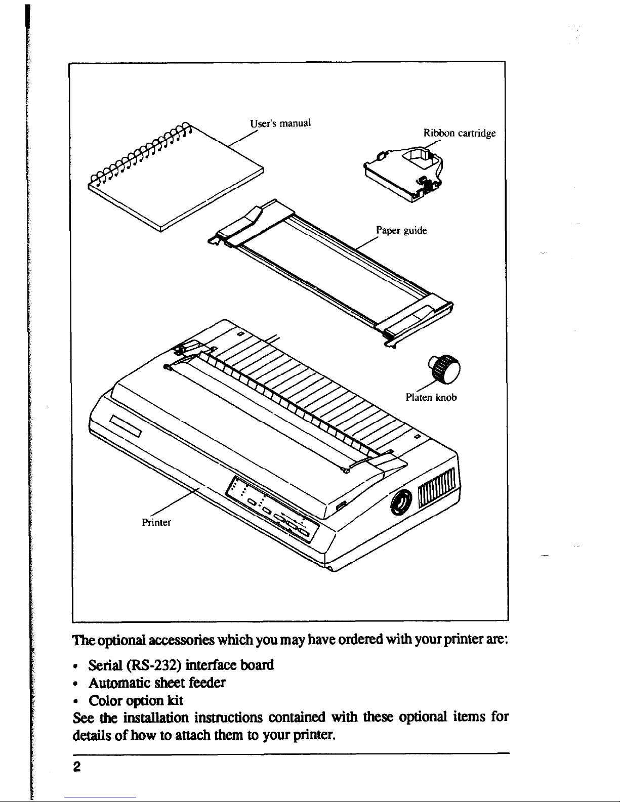
Now unpack the contents of the printer shipping container, and make sure
that you have the following:
. The printer itself
. Paper guide assembly
l The platen knob
9 A fabric ribbon
If any of these items am missing, contact your supplier.
1
User’s manual
Theoptional
accessories which you may have ordered with your printer are:
. Serial (RS-232) interface hoard
. Automatic sheet feeder
9 Color option kit
See the installation instructions contained with these optional items for
details of how to attach them to your printer.
2
Setting up
Place your printer in the position where it is going to be permanently sited,
and remove all packing material from inside the top cover. This packing
material is intended to prevent damage to the printer in transit. You may like
to keep this packing with the printer carton if you intend transporting the
printer for use at a different location.
-
.
laten knob
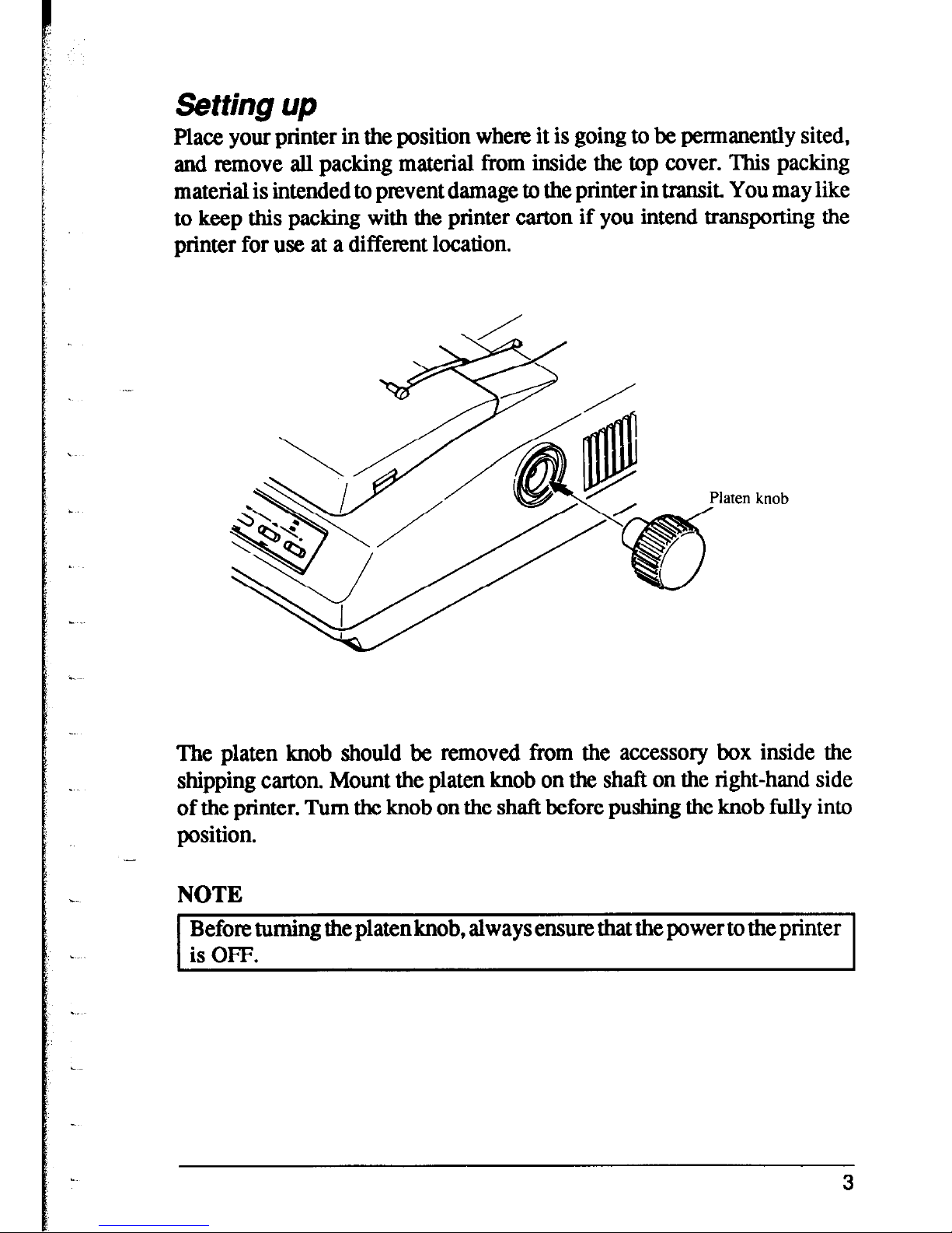
The platen knob should be removed from the accessory box inside the
shipping carton. Mount the platen knob on the shaft on the right-hand side
of the printer. Turn the knob on the shaft before pushing the knob fully into
position.
-
.
NOTE
Before turning the platenknob, always ensure that the power to the printer
is OFF.
3
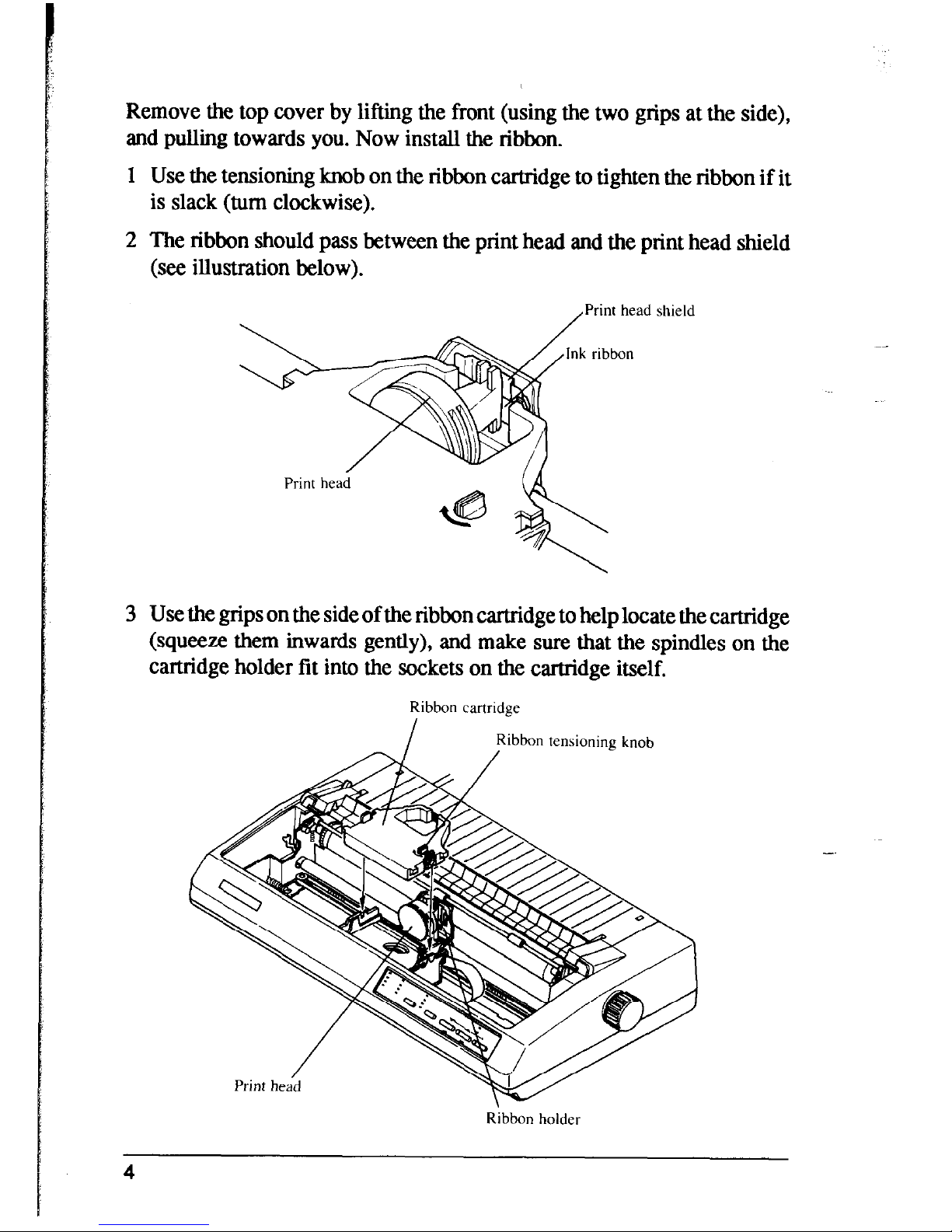
Remove the top cover by lifting the front (using the two grips at the side),
and pulling towards you. Now install the ribbon.
1 Use the tensioning knob on the ribbon cartridge to tighten the ribbon if it
is slack (turn clockwise).
2 The ribbon should pass between the print head and the print head shield
(see illustration below).
,Print head shield
3 Use the grips on the side of the ribbon cartridge to help locate the cartridge
(squeeze them inwards gently), and make sure that the spindles on the
cartridge holder fit into the sockets on the cartridge itself.
Ribbon cartridge
I
Ribbon tensioning
knob
Ribbon holder
4
*
b.
c
L
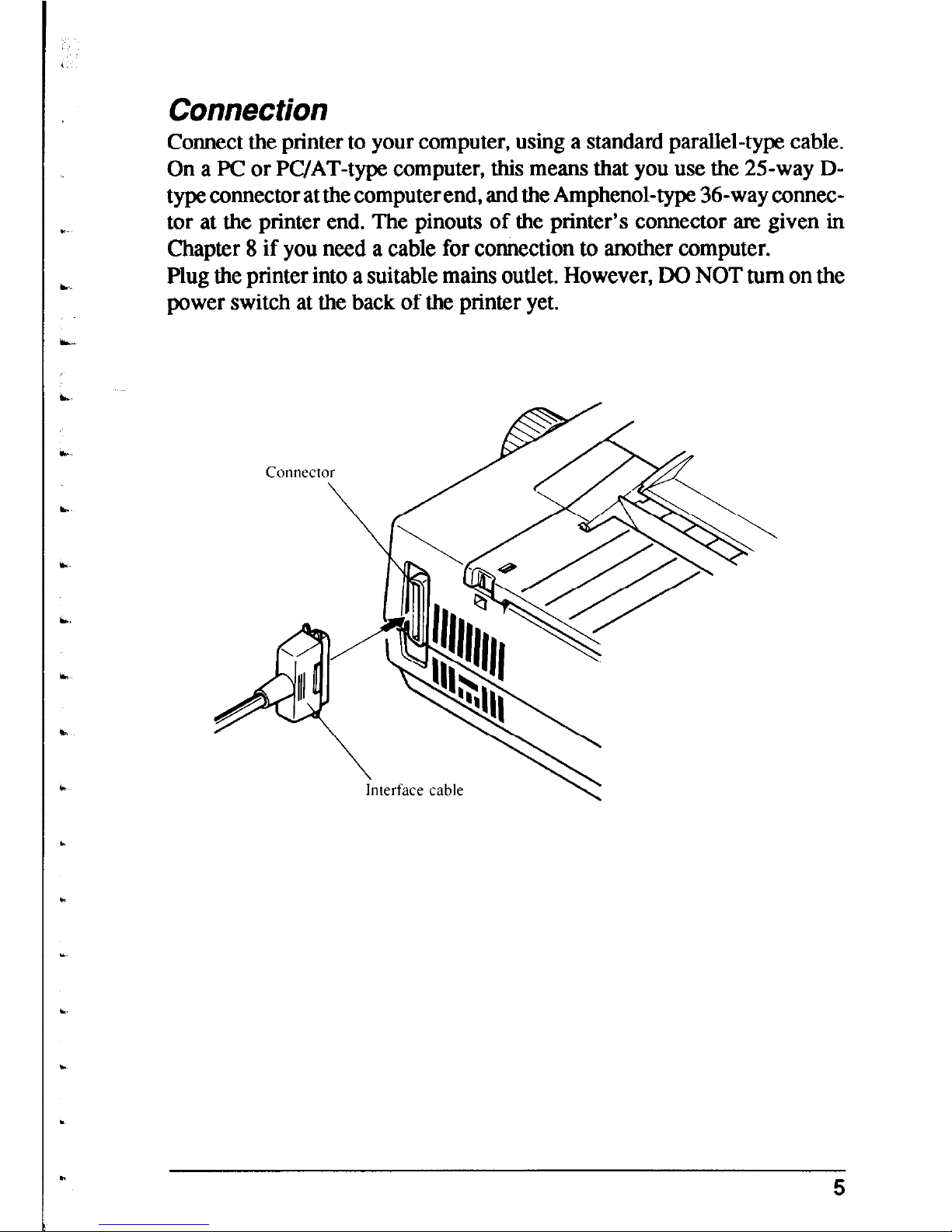
Connection
Connect the printer to your computer, using a standard parallel-type cable.
On a PC or PC/AT-type computer, this means that you use the 25-way Dtype connector at the computer end, and the Amphenol-type 36-way connector at the printer end. The pinouts of the printer’s connector are given in
Chapter 8 if you need a cable for connection to another computer.
Plug the printer into a suitable mains outlet. However, DO NOT turn on the
power switch at the back of the printer yet.
nterface cable
5
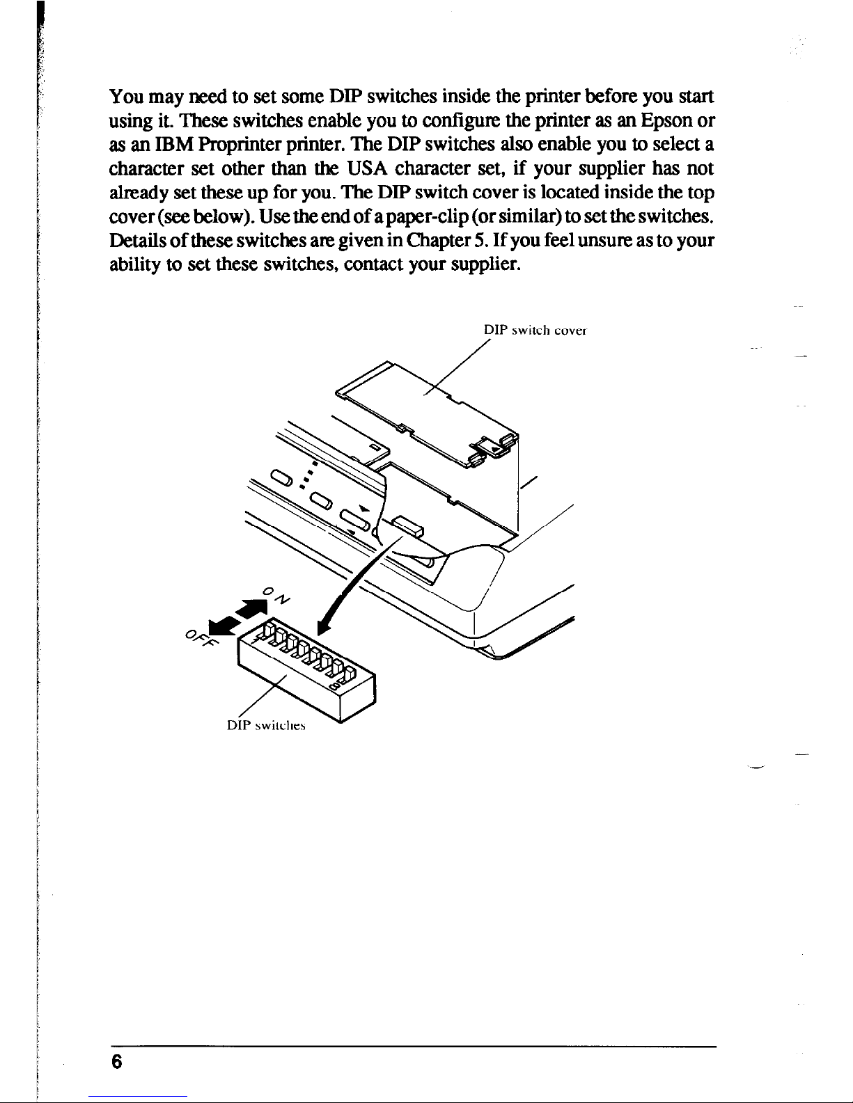
You may need to set some DIP switches inside the printer before you start
using it. These switches enable you to configure the printer as an Epson or
as an IBM Proprinter printer. The DIP switches also enable you to select a
character set other than the USA character set, if your supplier has not
already set these up for you. The DIP switch cover is located inside the top
cover (see below). Use the end of a paper-clip (or similar) to set the switches.
Details of these switches are given in Chapter 5. If you feel unsure as to your
ability to set these switches, contact your supplier.
DIP switch cover
6
LOADING PAPER
The following sections explain how to load paper - single-sheet (cut-sheet),
without the Automatic Sheet feeder, and also the operations necessary for
loading continuous (fanfold) stationery.
If you are using the Automatic Sheet Feeder, please refer to the instructions
supplied with the Automatic Sheet Feeder unit.
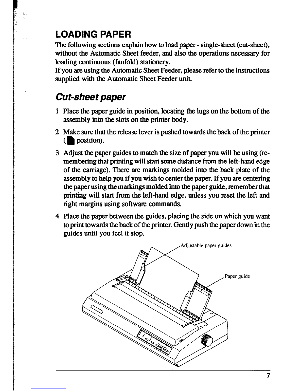
Cut-sheet paper
Place the paper guide in position, locating the lugs on the bottom of the
assembly into the slots on the printer body.
Make sure that the release lever is pushed towards the back of the printer
(h position).
Adjust the paper guides to match the size of paper you will be using (remembering that printing will start some distance from the left-hand edge
of the carriage). There are markings molded into the back plate of the
assembly to help you if you wish to center the paper. If you am centering
the paper using the markings molded into the paper guide, remember that
printing will start from the left-hand edge, unless you reset the left and
right margins using software commands.
Place the paper between the guides, placing the side on which you want
to print towards the back of the printer. Gently push the paper down in the
guides until you feel it stop.
Adjustable paper guides
7
5 Turn on the power using the switch at the back of the printer. The printer
will beep, indicating that no paper is in position for printing. The orange
PAPER indicator also shows this.
6 Now press the
~:,~Fp~~~ button. The paper bail will move clear of the paper,
and the paper will lx fed and adjusted past the print head to a position
ready for printing. The paper bail will be moved back to grip the paper
against the platen, and the print head will move to the start position.
The actual vertical position of the paper after auto-loading is determined by
the Memory Switch setting (see Chapter 3).
The vertical position of the paper can be finely adjusted by means of the
micro feed function (see Chapter 2).
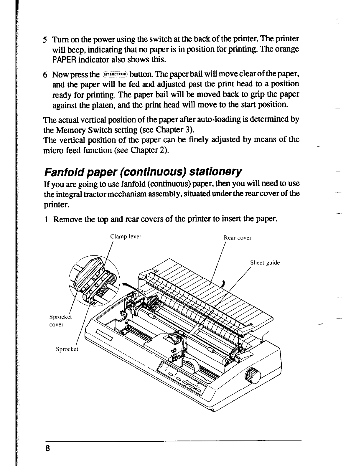
Fanfold paper (continuous) stationery
If you are going to use fanfold (continuous) paper, then you will need to use
the integral tractor mechanism assembly, situated under the rear cover of the
printer.
1 Remove the top and rear covers of the printer to insert the paper.
Clamp lever
Rear cover
-
-
-
-
8
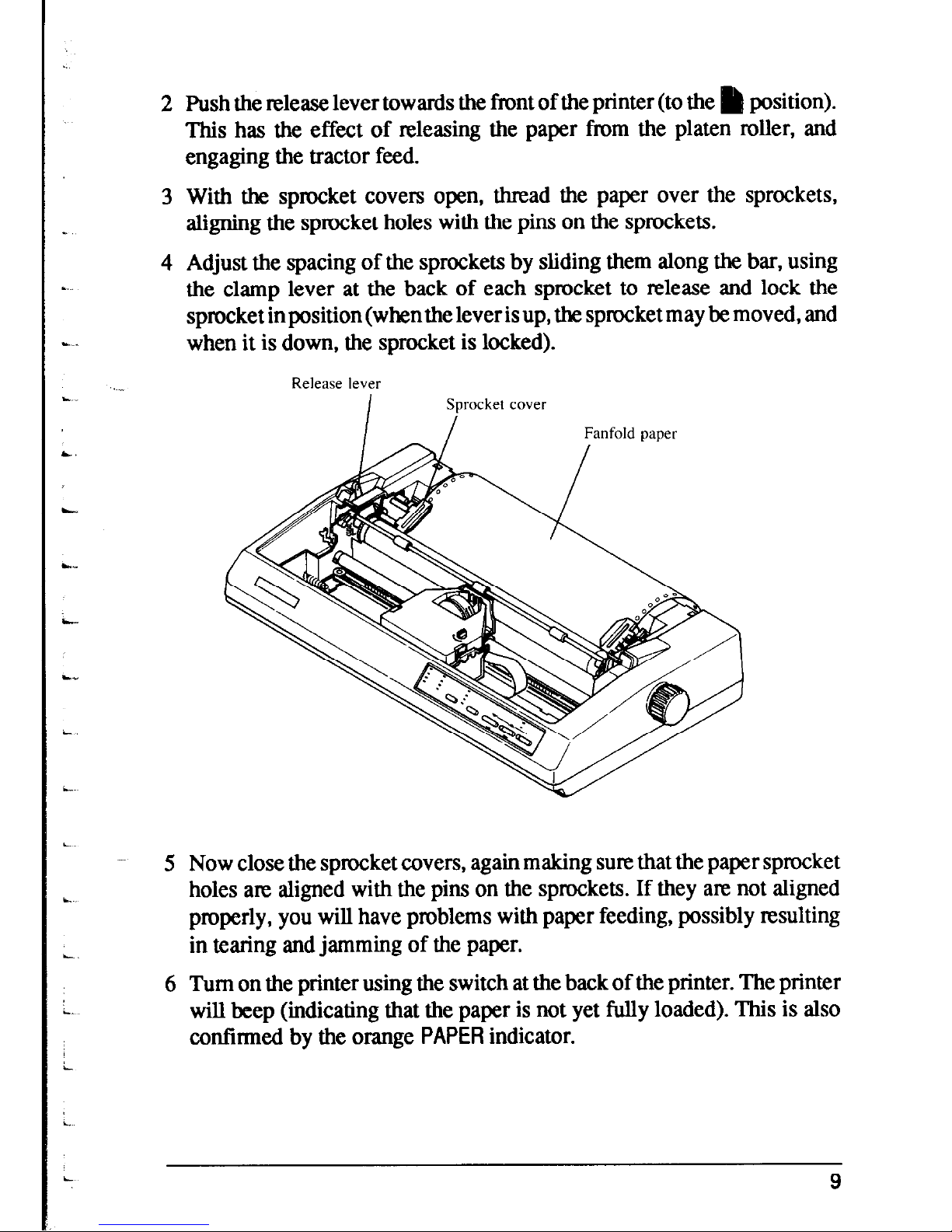
2 Push the release lever towards the front of the printer (to the h position).
This has the effect of releasing the paper from the platen roller, and
engaging the tractor feed.
3 With the sprocket covers open, thread the paper over the sprockets,
aligning the sprocket holes with the pins on the sprockets.
4 Adjust the spacing of the sprockets by sliding them along the bar, using
the clamp lever at the back of each sprocket to release and lock the
sprocket in position (when the lever is up, the sprocket may be moved, and
when it is down, the sprocket is locked).
5 Now close the sprocket covers, again making sure that the paper sprocket
holes are aligned with the pins on the sprockets. If they are not aligned
properly, you will have problems with paper feeding, possibly resulting
in tearing and jamming of the paper.
6 Turn on the printer using the switch at the back of the printer. The printer
will beep (indicating that the paper is not yet fully loaded). This is also
confinned by the orange PAPER indicator.
9
7 Now press the @5SE3 button. The paper bail will move clear of the paper,
and the paper will be fed and adjusted past the print head to a position
ready for printing. The paper bail will be moved back to grip the paper
against the platen, and the print head will move to the start position. As
when loading cut-sheet paper, the Memory Switch setting will determine
the initial position of the paper after auto-feeding, and the micro feed
function may be used to adjust the paper position.
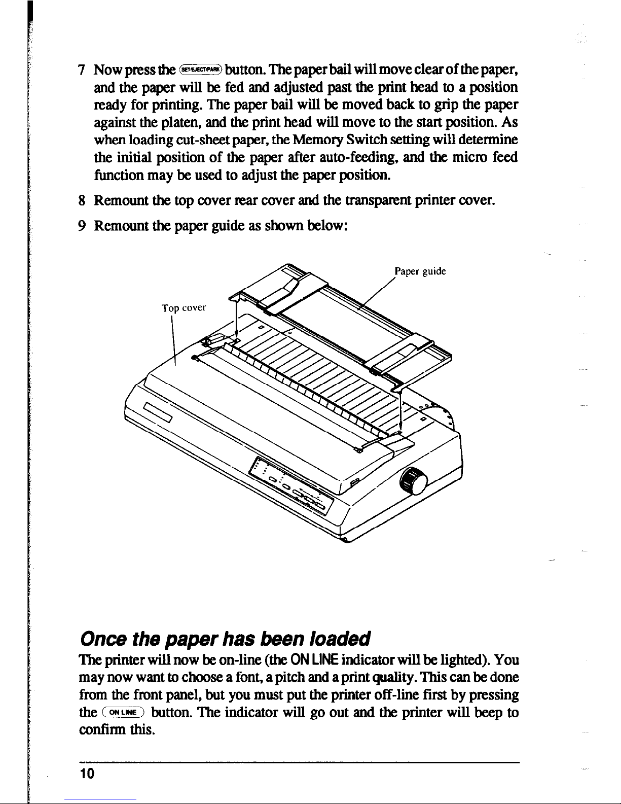
8 Remount the top cover rear cover and the transparent printer cover.
9 Remount the paper guide as shown below:
Once the paper has been loaded
The printer will now be on-line (the ON LINE indicator will be lighted). You
may now want to choose a font, a pitch and a print quality. This can be done
from the front panel, but you must put the printer off-line first by pressing
the (IEEE2 button. The indicator will go out and the printer will beep to
confirm this.
10
Chapter 2
FRONT PANEL CONTROLS
The following section describes the front panel controls and indicators on
your printer, together with a description of the functions performed by them.
CONTROLS AND INDICATORS
The following is a brief guide to the controls and indicators on the front
panel.
Controls
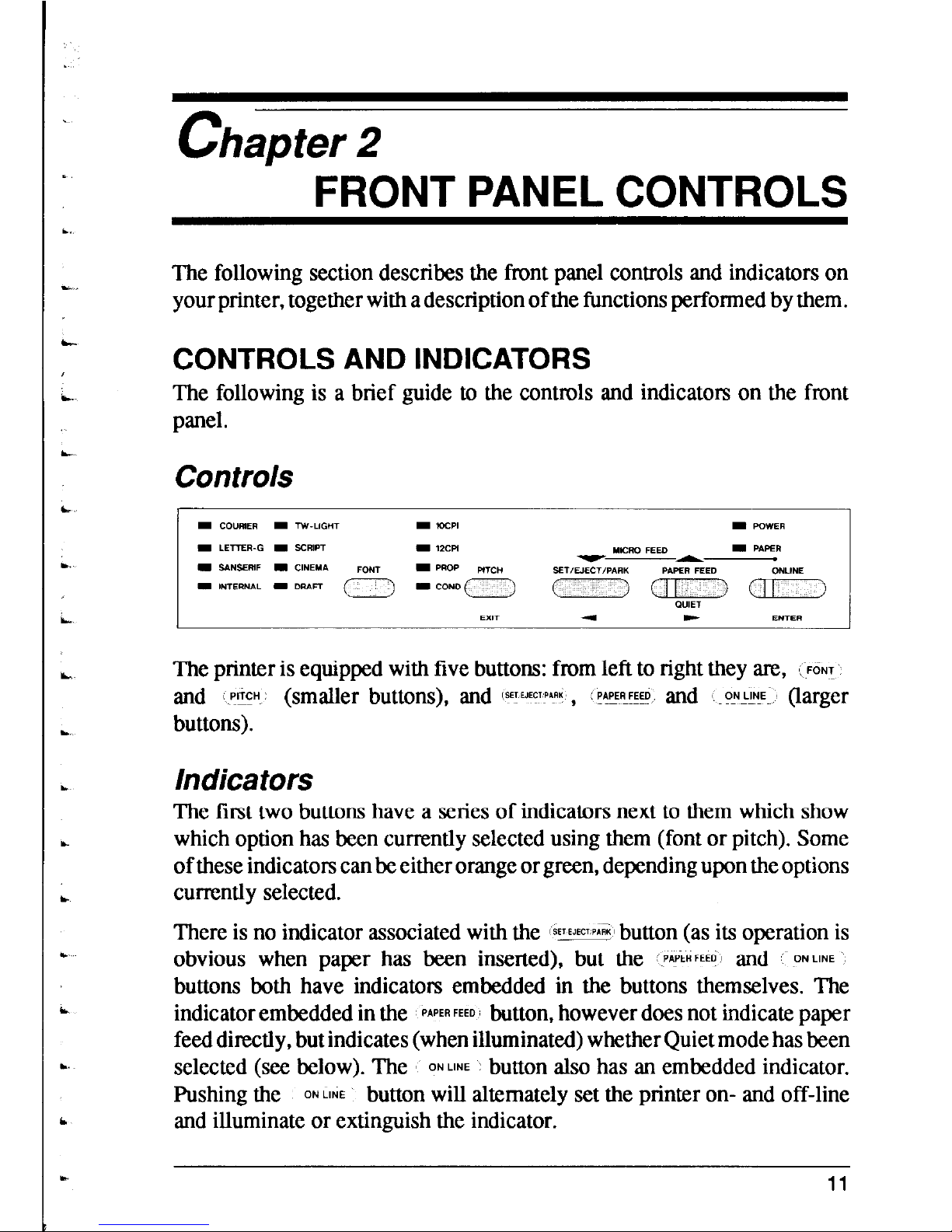
The printer is equipped with five buttons: from left to right they are,
\ FONT
and 1 EH (smaller buttons), and FJECV , L PCED and ~ON~~F (larger
buttons).
Indicators
The first two buttons have a series of indicators next to them which show
which option has been currently selected using them (font or pitch). Some
of these indicators can be either orange or green, depending upon the options
currently selected.
There is no indicator associated with the
ITEE+ button (as its operation is
obvious when paper has been inserted), but the PAPERFEED’ and ONLINE
buttons both have indicators embedded in the buttons themselves. The
indicator embedded in the PAPER FEED’ button, however does not indicate paper
feed directly, but indicates (when illuminated) whether Quiet mode has been
selected (see below). The ONME button also has an embedded indicator.
Pushing the
0~ ME button will alternately set the printer on- and off-line
and illuminate or extinguish the indicator.
11
In addition to these indicators, there are two others, POWER and PAPER. The
POWER indicator will illuminate when power is supplied to the printer, and
the PAPER indicator will illuminate when no paper has been inserted.
PITCH SETTING
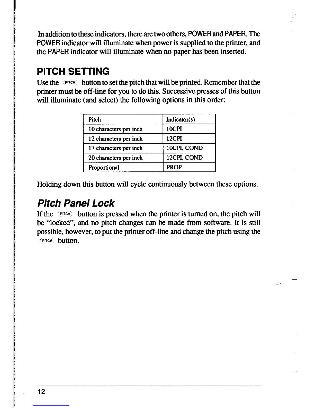
Use the (PIT% button to set the pitch that will be printed. Remember that the
printer must be off-line for you to do this. Successive presses of this button
will illuminate (and select) the following options in this order:
Pitch
Indicator(s)
10 charactexx per inch
locP1
12 characters per inch
12CPI
17 characters per inch
locP1, COND
20 characters per inch
12CP1, COND
Proportional
PROP
Holding down this button will cycle continuously between these options.
,
Pitch Pane/ Lock
I
If the plyEn> button is pressed when the printer is turned on, the pitch will
be “locked”, and no pitch changes can be made from software. It is still
possible, however, to put the printer off-line and change the pitch using the
1
KCZ button.
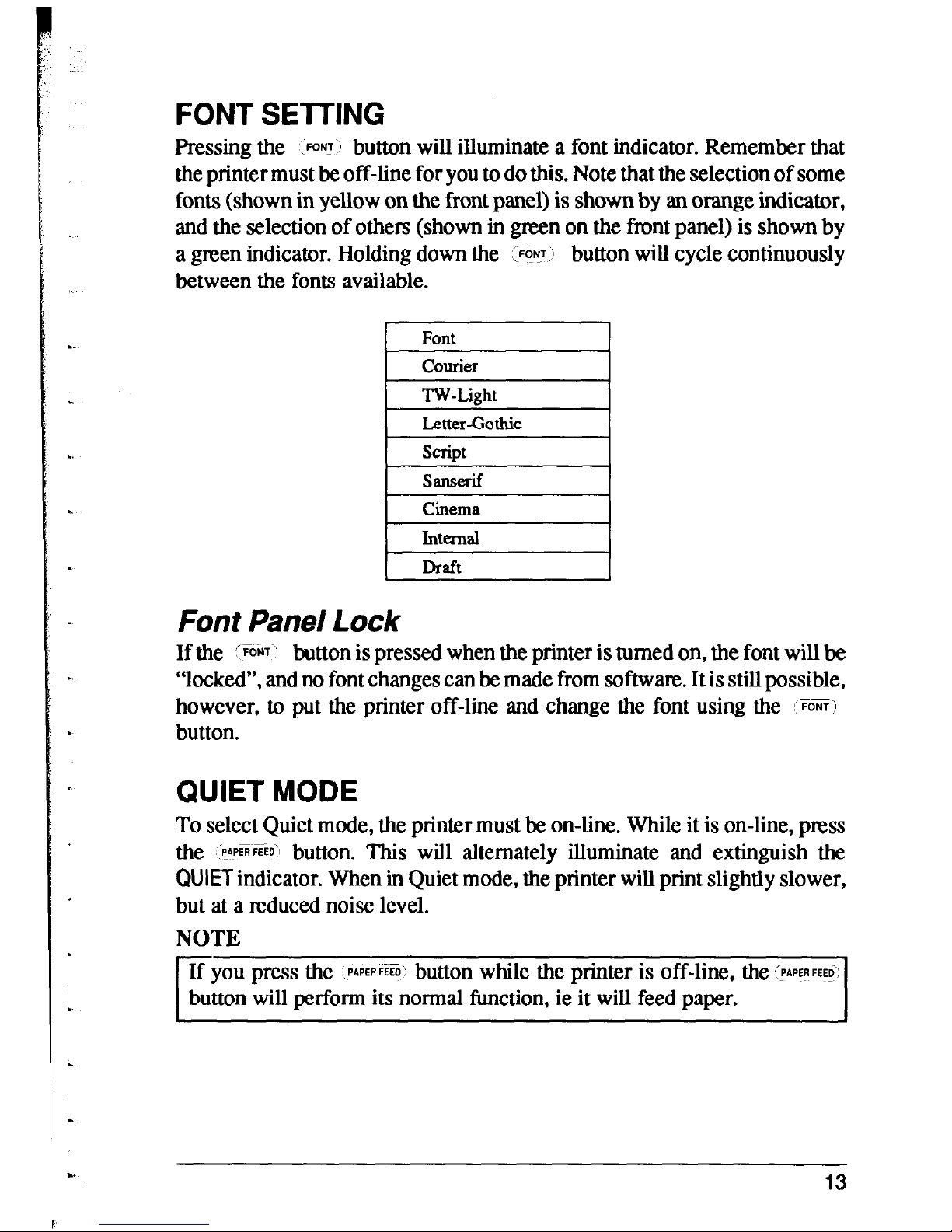
FONT SElTING
Pressing the
.%Y button will illuminate a font indicator. Remember that
the printer must be off-line for you to do this. Note that the selection of some
fonts (shown in yellow on the front panel) is shown by an orange indicator,
and the selection of others (shown in green on the front panel) is shown by
a green indicator. Holding down the :FOVT,
button will cycle continuously
between the fonts available.
Font
courier
TW-Light
Letter-Gothic
script
SaIlSerif
Cinema
Internal
Draft
Font Panel Lock
If the ‘FONT-
button is pressed when the printer is turned on, the font will be
“locked”, and no font changes can be made from software. It is still possible,
however, to put the printer off-line and change the font using the +oNi\l
button.
QUIET MODE
To select Quiet mode, the printer must be on-line. While it is on-line, press
the pp~pfi~~~~~ button. This will alternately illuminate and extinguish the
QUIET indicator. When in Quiet mode, the printer will print slightly slower,
but at a reduced noise level.
NOTE
If you press the
PAPERFEW button while the printer is off-line, the @GE3
button will perform its normal function, ie it will feed paper.
13
PAPER HANDLING
The following sections describe the ways in which you can control paper
feeding, etc by means of the front panel controls:
Form feed
A form feed can be achieved from the front panel in the following way:
1 Put the printer off-line, by pressing the
\ ONL%:~ button, so that the
indicator is extinguished.
2 Press the PAPERFEED’ button, and keep it depressed.
3 Press the LzE button momentarily.
4 The paper will then move forward to the top of the next sheet (fanfold
paper), or eject a cut sheet.
5 Set the printer on-line again (:oNG+F> button) to resume printing.
Paper parking
Paper parking is useful if you are using fanfold paper, and you want to print
a document on one or two sheets of cut-sheet paper. The printer “parks” the
fanfold paper safely out of the way, so that you do not need to unload the
paper before inserting cut-sheet paper, then, when you have finished
printing on cut-sheet paper, moves the fanfold paper back to its original
position so that you can restart printing.
To use this facility, follow the instructions below:
1 Put the printer off-line (press the
0~ LINE \ button, so that the indicator goes
out).
-
2 Press the WYP*RI, button, so that the fanfold paper is moved out of the
paper path.
3 Now move the release lever to the rear of the printer ( h position) to select
cut-sheet paper (disengaging the fanfold sprockets).
NOTE
I
If you do not move the release lever at this stage, the printer will warn you
at the next step by emitting a continuous series of beeps.
14

4 Insert the cut sheet paper in the paper guides
5 Press the (@SW button in order to feed the cut sheet to the starting print
position. The printer will automatically go on-line.
6 Print as normal on the cut sheet(s), and when you have finished printing,
put the printer Off-he (by ptBsing the ‘j ON LINE ;I button again).
7 If the software has not done this for you, eject the paper by pressing the
,@ZRX) button.
8 Move the release lever to the front of the paper (Is position) to select
fanfold paper (engaging the fanfold sprockets).
9 Now feed the fanfold paper to the print position by pressing the FEES
button. The paper will move to its former print position, and the printer
will automatically go on-line.
You are now ready to start printing on fanfold paper again.
Short tear-off function
The short-tear-off function is handy when using fanfold paper. It ejects the
papers0 that the perforation is just above the transparent cover, allowing you
tear it off without having to open up the printer. It then reverses the paper
feed after you have tom off the paper, thereby starting printing at the top of
the next form. This feature is especially useful if you are using pre-printed
stationery (such as invoices, etc), which will not be printed all together.
To use the short tear-off function, press the :- ONJW button when the printer
is on-line, and hold it down for a few seconds. When you release the button,
the printer will go off-line, and the paper will move up a few inches, allowing
you to tear off the form.
To return the paper to its previous position, press the i ONL!!E~ button once
again. When you release the button, the printer will return to its on-line
status, and the paper will be fed backwards, with the print head aligned with
the top of the next form.
,
15
Micro Feed
The Micro Feed facility is useful if you wish to align the paper exactly. It
feeds the paper forwards or backwards in 1/216th inch increments.
To use this feature, put the printer off-line (using the :IKLIF~ button).
Then press the 5 ~~
(ONLINE) button, and either the /p*pEE; button (to feed the
paper forwards), or the EFEG3 button (to feed the paper backwards).
Holding down these buttons continuously will continue to feed the paper for-
wards or backwards in small increments.
BUFFER CLEAR/RESET
It is possible to clear the buffer of the printer or to return it to its power-on
status by using the front panel buttons without having to turn the power off
and on. To do this, put the printer off-line (press the OEM button), and then
press the CON button again. Before releasing the -ON button, hold
down the :~OFIT button. Releasing the : %F; button within two seconds of
holding it down (before releasing the 1C%!C button) will clear the data in
the buffer. Releasing the button after two seconds (again, before releasing
fie (-FLlNf ‘1
~-
button) will reset the printer back to the settings at power-on.
TEST AND MAINTENANCE SETTINGS
The printer is equipped with a number of functions to assist testing and main-
tenance. Since it is anticipated that they will not be used very often, they are
not described here, but in Chapter 6.
However, briefly, they are:
l A text test print mode
l A short test print mode
l A long test print mode
l A hexadecimal dump mode
l A bidirectional print test
16
a.
L.
L-
L.
b,
. .
L
.
L
Chapter 3
SETTING UP
THE MEMORY SWITCHES
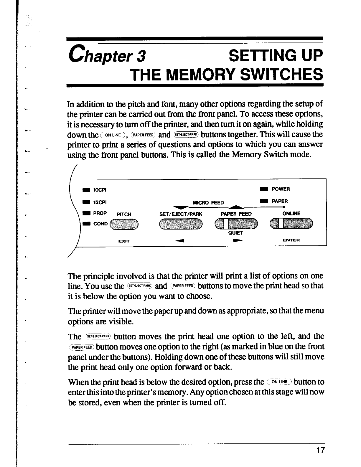
In addition to the pitch and font, many other options regarding the setup of
the printer can be carried out from the tint panel. To access these options,
it is necessary to turn off the printer, and then turn it on again, while holding
down the (ON, (P?PERFEED: and 6E!ZE3 buttons together. This will cause the
printer to print a series of questions and options to which you can answer
using the front panel buttons. This is called the Memory Switch mode.
I POWER
MICRO FEED
I PAPER
SET/EJECT/PARK
PAPER FEED
ONLINE
QUIET
F
ENTER
The principle involved is that the printer will print a list of options on one
l&. you use the $+*+I
and <YF~F+ buttons to move the print head so that
it is below the option you want to choose.
The printer will move the paper up and down as appropriate, so that the menu
options are visible.
The @EE+ button moves the print head one option to the left, and the
,%+ FFD\/ button moves one option to the right (as marked in blue on the front
panel under the buttons). Holding down one of these buttons will still move
the print head only one option forward or back.
When the print head is below the desired option, press the , ON E_\ button to
enter this into the printer’s memory. Any option chosen at this stage will now
be stored, even when the printer is turned off.
17
When you press the ’ oKi& ’ button to enter an option, a “*” (asterisk) will
be printed to confinn that the option has been chosen.
The menus are organized in a hierarchical (tree-structured) fashion. Some
menus do not choose options directly, but instead, move down to other
menus. To move up through the menu structure towards the “mot” or
‘(trurW, use the
PITCH button m m EXIT
button (as marked in blue
underneath the button).
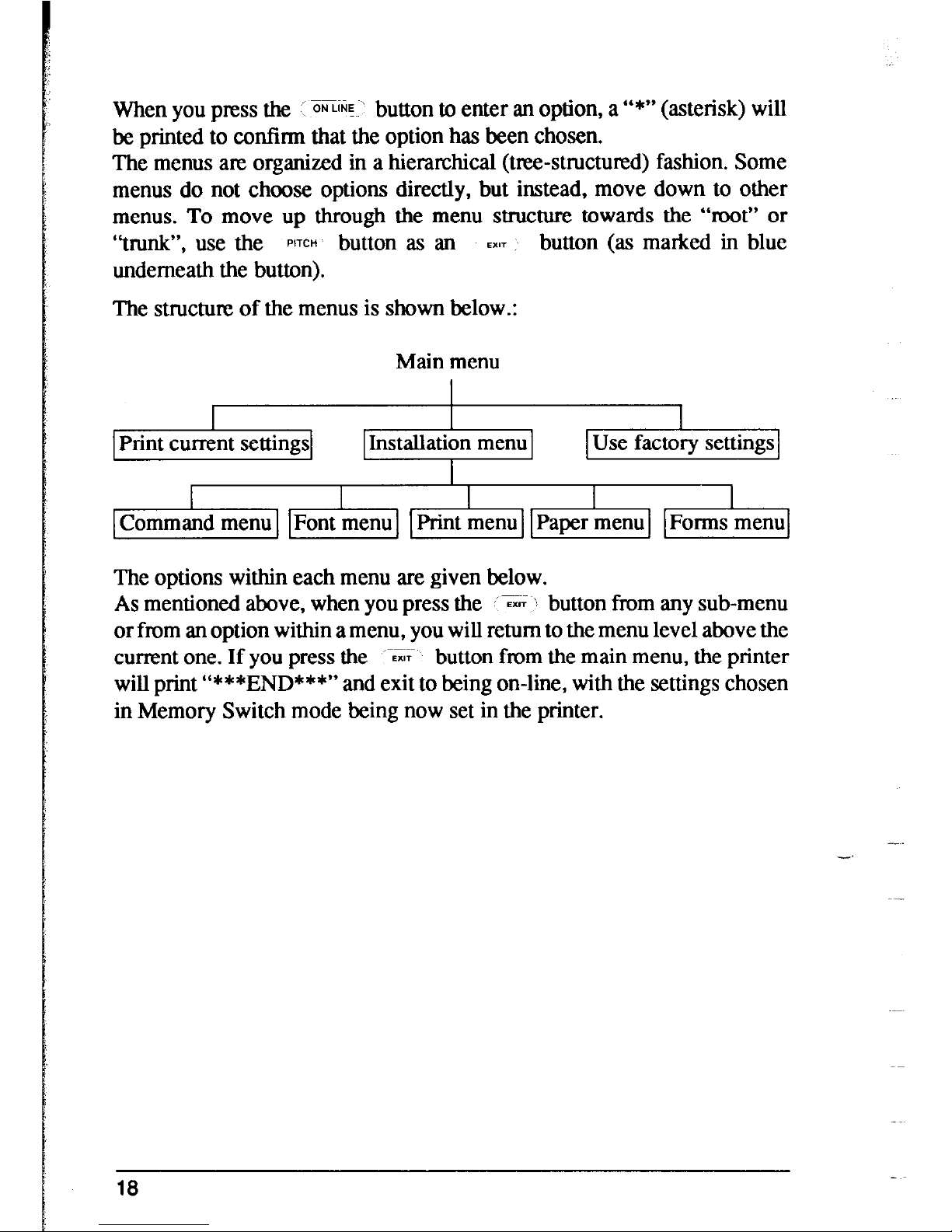
The structure of the menus is shown below.:
Main menu
Print current settings
I I I
I
Command menu 1 IFont menu 1 1 Print menu Paper menu I Forms menu
The options within each menu are given below.
As mentioned above, when you press the EAT X button from any sub-menu
or from an option within a menu, you will return to the menu level above the
current one. If you press the
-G; button from the main menu, the printer
will print “***END***” and exit to being on-line, with the settings chosen
in Memory Switch mode being now set in the printer.
18

MENU OPTIONS
The following is a list of the options within the menus, and their meanings,
together with the prompts printed in Memory Switch mode. The prompts are
given in capital letters in square brackets, thus: [OFF]. Factory settings are
marked here with an asterisk (for example, [ON*]). A summary of factory
settings is also provided following this section.
Command Menu
This menu allows you to set up various parameters controlling the overall
setup of the printer:
RAM USAGE
QUIET MODE
GRAPHICS
DIRECTION
AUTO ON-LINE
The printer RAM may be used as a print buffer
[BUFFER*], for downloading fonts [DOWNLOAD], or
as a single-line buffer [lLINE.BUFFER].
The printer may either print slower and quieter [ON], or
faster, making slightly more noise [OF].
When printing in graphics mode, the printer may either
print biditeetionally (in alternate directions) for speed
[BI*] or in one direction only (unidirectional for increased accuracy KINI]. For practically all purposes,
however, biclireetional printing is sufficiently accurate.
If this is set [ON*], then when paper is inserted, the
printer will automatically come on-line. If set [OFFJ, then
you will have to press the button to bring the printer on-
line.
Font Menu
This menu allows you to set two parameters concerning fonts which will be
automatically selected whenever you turn on the printer:
ZERO STYLE In computer usage, a zero is often written with a slash
through it, as follows: @“. This style is called
[SLASHED]. If a zero is written as a slightly thinner
capital%“, without the slash (“O”), this is may be chosen
by selecting PIORMAL*].
NLQ FONT STYLE
This option allows you to choose the default font selected
when NLQ mode is selected. All available fonts are given
as options. The default is [COURIER*].
19
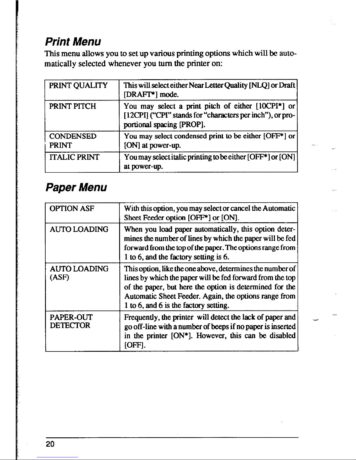
Print Menu
This menu allows you to set up various printing options which will be automatically selected whenever you turn the printer on:
PRINT QUALITY
This will select either Near Letter Quality lNLQ1 or Draft
[DRAFTC] mode.
PRINTPITCH
CONDENSED
PRINT
ITALIC PRINT
You may select a print pitch of either [lOCPI*] or
[ 12CPI] (L‘CPIII stands for “characters per inch”), or pro-
portional spacing [PROP].
You may select condensed print to be either [OF] or
[ON] at power-up.
You may select italic printing to be either [OFFr] or [ONI
at power-up.
Paper Menu
OPTION ASF
AUTO LOADING
AUTO LOADING
WF)
PAPER-OUT
DETECTOR
With this option, you may select or cancel the Automatic 1
Sheet Feeder option [OFF*] or [ONI.
1
When you load paper automatically, this option determines the number of lines by which the paper will be fed
forward from the top of the paper. The options range from
1 to 6, and the factory setting is 6.
This option, like the one above, determines the number of
lines by which the paper will be fed forward from the top
of the paper, but here the option is determined for the
Automatic Sheet Feeder. Again, the options range from
1 to 6, and 6 is the factory setting.
Frequently, the printer will detect the lack of paper and
go off-line with a number of beeps if no paper is inserted
in the printer [ON*]. However, this can be disabled
mFl.
20
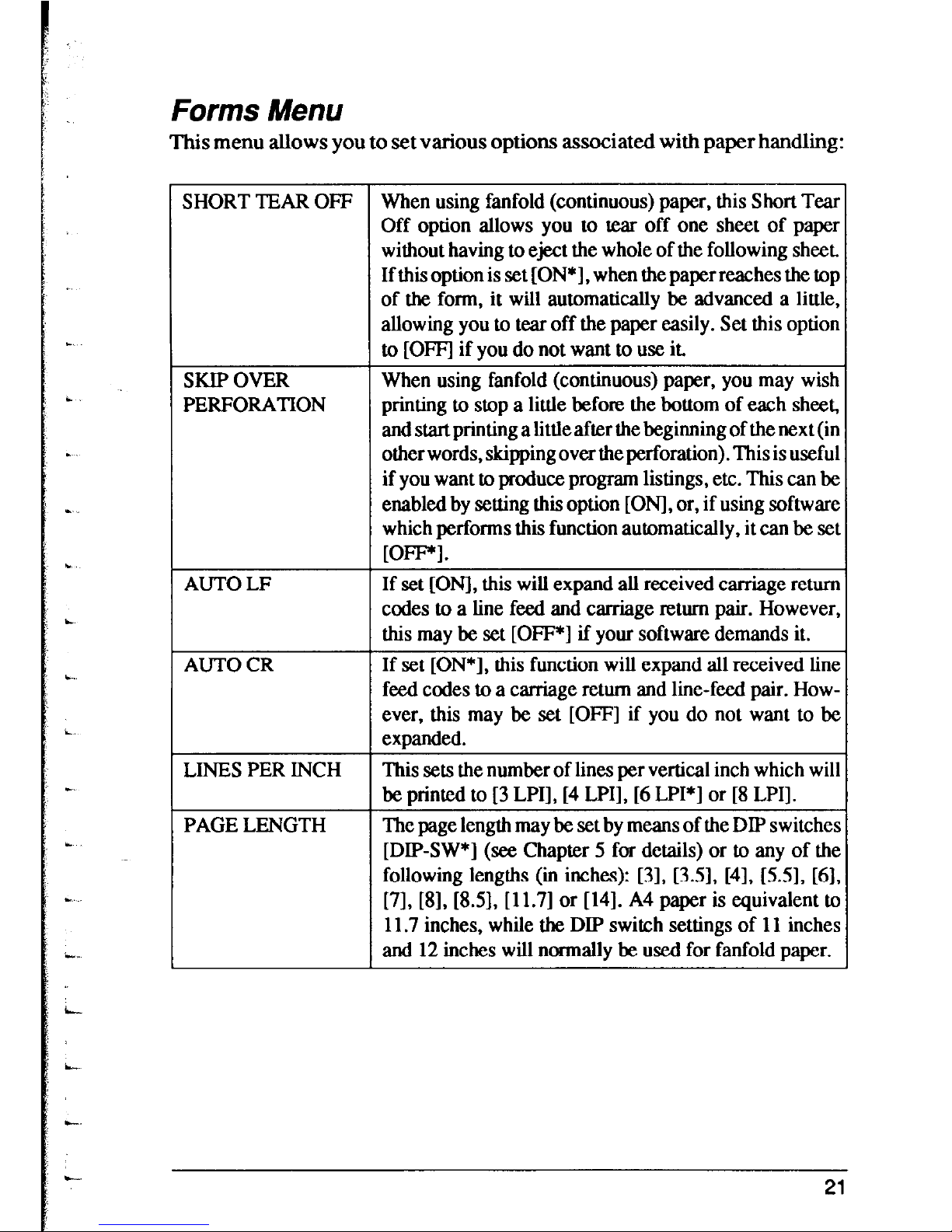
Forms Menu
This menu allows you to set various options associated with paper handling:
SHORT TEAR OFF When using fanfold (continuous) paper, this Short Tear
Off option allows you to tear off one sheet of paper
without having to eject the whole of the following sheet.
If this option is set [ON*], when the paper reaches the top
of the form, it will automatically be advanced a little,
allowing you to tear off the paper easily. Set this option
to [OFFI if you do not want to use it.
SKIP OVER
When using fanfold (continuous) paper, you may wish
PERFORATION
printing to stop a little before the bottom of each sheet,
and start printing a little after the beginning of the next (in
other words, skipping over the perforation). This is useful
if you want to produce program listings, etc. This can be
enabled by setting this option [ONI, or, if using software
which performs this function automatically, it can be set
Wm.
AUTO LF If set [ONI, this will expand all received carriage return
codes to a line feed and carriage return pair. However,
this may be set [OFF*] if your software demands it.
AUTO CR
If set [ON*], this function will expand all received line
feed codes to a carriage retum and line-feed pair. However, this may be set [OFF] if you do not want to be
expanded.
LINES PER INCH
This sets the number of lines per vertical inch which will
be printed to [3 LPI], [4 LPI], [6 LPI*] or [8 LPI].
PAGE LENGTH The page length may be set by means of the DIP switches
[DIP-SW*] (see Chapter 5 for details) or to any of the
following lengths (in inches): 131, 13.51, [41, [X5], [6],
[7], [8], [8.5], [11.7] or [141. A4 paper is equivalent tc
11.7 inches, while the DIP switch settings of 11 inches
and 12 inches will normally be used for fanfold paper.
21
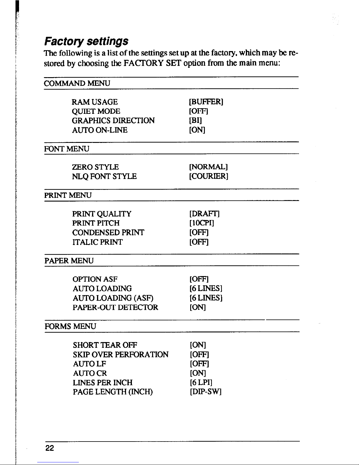
Factory settings
The following is a list of the settings set up at the factory, which may be re-
stored by choosing the FAmORY SET option from the main menu:
coMb4ANDMENu
RAM USAGE
[B-RI
QUIET MODE
DTI
GRAPHICS DIRECTION
[BII
AUTO ON-LINE
KNI
FONT MENU
ZERO STYLE
[NOR==1
NLQ FONT STYLE
[COURIER]
PRINTMENU
PRINT QUALITY
[DRW
PRINT PITCH
[locpIl
CONDENSED PRINT
[OFFJ
ITALIC PRINT
WFI
PAPER MENU
OPTION ASF
WFl
AUTO LOADING
[6 LINES]
AUTO LOADING (ASF)
[6 LINES]
PAPER-OUT DETECTOR
mJl
FORMS MENU
SHORT TEAR OFF
SKIP OVER PERFORATION
AUTO LF
AUTO CR
LINES PER INCH
PAGE LENGTH (INCH)
WI
WFI
WFI
ml
[6 LPI]
[DIP-SW]
22
L.
c
chapter 4
EMULATIONS
AND ESCAPE CODES
EMULATIONS
The printer has two emulation modes: standard mode and IBM mode.
In standard mode, the printer emulates the functions of the Epson EX-800
and EX- 1000 printers. Additional command codes am included as a superset
of these emulations.
In IBM mode, the printer emulates the IBM Proprinter II. Additional
command codes are included as a superset of these emulations.
The emulation is changed by means of DIP switch 1. When ON, the printer
will be in standard mode, and when OFF, the printer will be in IBM emulation mode (see Chpter 5). It is not possible to change the emulation mode by
means of software control or the front panel controls.
NOTE
Remember to turn off the printer before making any DIP switch changes.
1
NUMERICAL REPRESENTATION
When in either standard or IBM mode, any numerical parameters taken by
command sequences are usually binary rather than ASCII numerical values.
In this manual, any ASCII values will be represented in quotes, eg “21” will
represent the ASCII string 32h concatenated with 31h (in BASIC,
CHR$(SO)+CHR$(S 1)). Usually in these examples, however, hexadecimal
values wilI be quoted, as shown by the lowercase “h” following the number,
eg 32h.
Binary numbers over FFh am obtained by dividing the number into two
bytes, the first being the low byte, and the second being the high byte. In this
way, the value 123h will be divided into the two following bytes: 23h and
Olh.
If negative numbers are required, they are obtained by subtracting the
absolute value of the negative number from 65536 (lOOOOh), and dividing
the result into high and low bytes. For instance, to represent the number - lOh,
the following operation is carried out:
23
<
1OOOOh - 10h = FFFOh
and the result is divided into the two bytes of FOh and FFh.
If “non-printable” codes are given, ie those codes from OOh through 1Fh and
7Fh, these codes will be enclosed in angle brackets, for example <DCl>.
The name in the angle brackets is that assigned to the code in the ASCII convention. The name of the character should not be used, the binary value
should be input. In the same way, it should be noted that the angle brackets
are not to be input - they are merely there as delimiters in the printed text.
Of course, in a program, a meaningful variable name can be given to these
characters, for instance (the following example is written in BASIC):
10 ESC$=CHR$(27) :BS$=CHR$(8)
20 LPRINT ESC$;BS$;
COMMAND CODES AND ESCAPE SEQUENCES
Some command codes are common to both the standard and IBM modes. In
the descriptions of the command codes, all command codes will be given,
together with a note of the modes to which each command code is applicable.
Most of the following command codes are available in both the standard
mode and the IBM emulation mode. If a command is common to both
modes, the descriptive heading is followed by “Both”. If the command is
specific to one mode, then either “Standard” or “IBM” will follow the
descriptive heading. Occasionally, there are two identical commands to
perform the same function. In these cases, the relevant sign follows the
escape sequence.
When parameters are given, the accompanying text describes whether the
parameter is an ASCII character or a binary value.
-
In the following descriptions, first the function of the command sequence is
given. This is followed by the emulation for which this command is
appropriate (“Standard”, “Both” or “IBM”).
24
 Loading...