

Page 1
iS10 Spa-Side Remote
(For IntelliTouch and CP3800 series systems)
Installation Guide
IMPORTANT SAFETY INSTRUCTIONS
READ AND FOLLOW ALL INSTRUCTIONS
SAVE THESE INSTRUCTIONS
Page 2
IMPORTANT SAFETY PRECAUTIONS
Important Notice:
Attention Installer: This manual contains important information about the installation, operation and safe use of this
product. This information should be given to the owner and/or operator of this equipment.
WARNING - Before installing this product, read and follow all warning notices and instructions which are included.
Failure to follow safety warnings and instructions can result in severe injury, death, or property damage.
Call (800) 831-7133 for additional free copies of these instructions.
WARNING - To reduce the risk of injury, do not permit children to use this product unless they are closely super-
vised at all times.
WARNING - The use of alcohol, drugs, or medication can greatly increase the risk of fatal hyperthermia in hot tubs
and spas.
WARNING - Control System is intended to control heaters with built-in high limit circuits ONLY. Failure to do so
may cause property damage or personal injury.
WARNING - Do not use this product to control an automatic pool cover. Swimmers may become entrapped
underneath the cover.
Contents
iS10 spa-side remote controller overview .............................................................................................................................. 1
Operating the iS10 remote controller ..................................................................................................................................... 1
Disable/Enable the iS10 spa-side remote .............................................................................................................................. 2
Setting up the iS10 spa-side remote from the IntelliTouch indoor control panel ...................................................................... 2
iS10 spa-side remote controller Installation .......................................................................................................................... 3
Recess mount installation ................................................................................................................................................ 4
Surface mount installation ............................................................................................................................................... 6
Wiring the iS10 remote to the IntelliTouch load center .......................................................................................................... 8
Adding an iS10 spa-side remote controller to IntelliTouch ................................................................................................... 10
Adding an iS10 remote controller to a CP3xxx system ...................................................................................................... 11
Upgrading from the SS8 to the iS10 remote ....................................................................................................................... 11
iS10 bracket guide template ............................................................................................................................................... 12
Technical Support
Sanford, North Carolina (8 A.M. to 5 P.M.)
Phone: (800) 831-7133
Fax: (919) 566-8920
Moorpark, California (8 A.M. to 5 P.M.)
Phone: (800) 831-7133
Fax: (805) 553-5515
Web sites: visit www.pentairpool.com and www.staritepool.com
© 2006 Pentair Water Pool and Spa, Inc. All rights reserved
This document is subject to change without notice
1620 Hawkins Ave., Sanford, NC 27330 • (919) 566-8000
10951 West Los Angeles Ave., Moorpark, CA 93021 • (805) 553-5000
Trademarks and disclaimers: IntelliTouch, Compool and the Pentair Water Pool and Spa logo are trademarks of Pentair Water Pool and Spa,
Inc. Other trademarks and trade names may be used in this document to refer to either the entities claiming the marks and names or their
products. Pentair Water Pool and Spa, Inc. disclaims proprietary interest in marks and names of others.
P/N 520208 - Rev B - 05/5/2006
Page 3
iS10 spa-side remote controller overview
T
5"
The iS10 spa-side remote is a double-insulated device UL and ETL listed to UL 1563 for use with the IntelliTouch pool and
spa control system, and the Compool CP series systems. The iS10 spa-side remote provides control of ten functions from
the spa location. The spa temperature can also be adjusted from the remote. Up to four iS10 remotes may be installed using
the IntelliTouch model i7+3, i9+3, i9+3S and i10+3D. The i5 and i5S IntelliTouch system, and the compool CP3 series
systems can support one iS10 remote. It is possible to use two iS10’s on an i5, i5S and CP3 system, however, the two iS10
remotes will mirror each other in functionality.
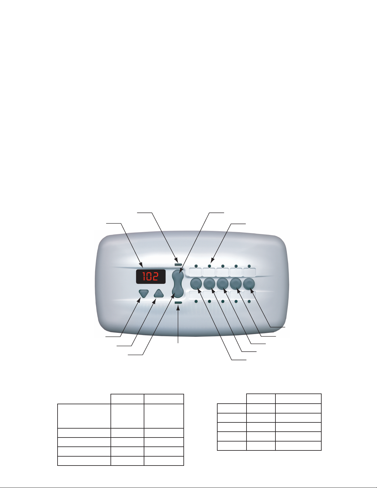
Operating the iS10 remote controller
The iS10 remote controller can control up to ten system functions, depending on the system being used. Each circuit
function can be labeled above or below the buttons to identify the button function. Pressing the “peanut-shaped” middle
button toggles between which row of circuit functions to activate when one of the five in-line buttons are pressed. An LED
indicator light above and below the toggle button indicates which row (top or bottom) is active. When one of the in-line
buttons is pressed, the adjacent LED indicator will be on indicating that the circuit has been activated. The default circuits
activated by each button are shown below. To change the default circuit function settings or configure different settings for
multiple iS10 remotes with IntelliTouch only, see page 2.
Spa temperature is displayed in the temperature display. The spa temperature may be adjusted up or down by pressing the
appropriate up or down arrow button. The current temperature display will blink while it is being adjusted. After setting the
desired temperature, the display shows the actual temperature as it adjusts to the set temperature. This only functions while
in the “Spa” mode. The temperature set by the iS10 is only temporary. When the “Spa” mode is switched OFF, the
temperature set at the IntelliTouch Indoor Control Panel will resume the next time the spa mode is activated using the “Set
manual heat” function (see the IntelliTouch User’s Guide (P/N 520102) for details. The “Spa” mode will automatically switch
off after 24 hours.
TOP ROW INDICATOR LIGHT
EMPERATURE DISPLAY
TOP ROW TOGGLE BUTTON
FUNCTION INDICATOR LIGHT
1
IN-LINE BUTTON "
TEMPERATURE DOWN
BOTTOM ROW TOGGLE BUTTON
TEMPERATURE UP
Default IntelliTouch Settings
BOTTOM ROW
INDICATOR LIGHT
IN-LINE BUTTON "2"
IN-LINE BUTTON "1"
Default Compool CP3XXX Settings
WORPOTWORMOTTOB
1NOTTUB
D3+01i,3+9i,3+7i,5i
S3+9i,S5i
APS
PMET-IH
21XUA5XUA
32XUA6XUA
LOOP
PMET-OL
1NOTTUBAPS4XUA
2LOOP5XUA
31XUA6XUA
42XUA7XUA
53XUAELBALIAVANU
43XUA7XUA
IN-LINE BUTTON "4"
IN-LINE BUTTON "3"
WORPOTWORMOTTOB
54XUA8XUA
iS10 Spa-Side Remote Installation Guide
Page 4
2
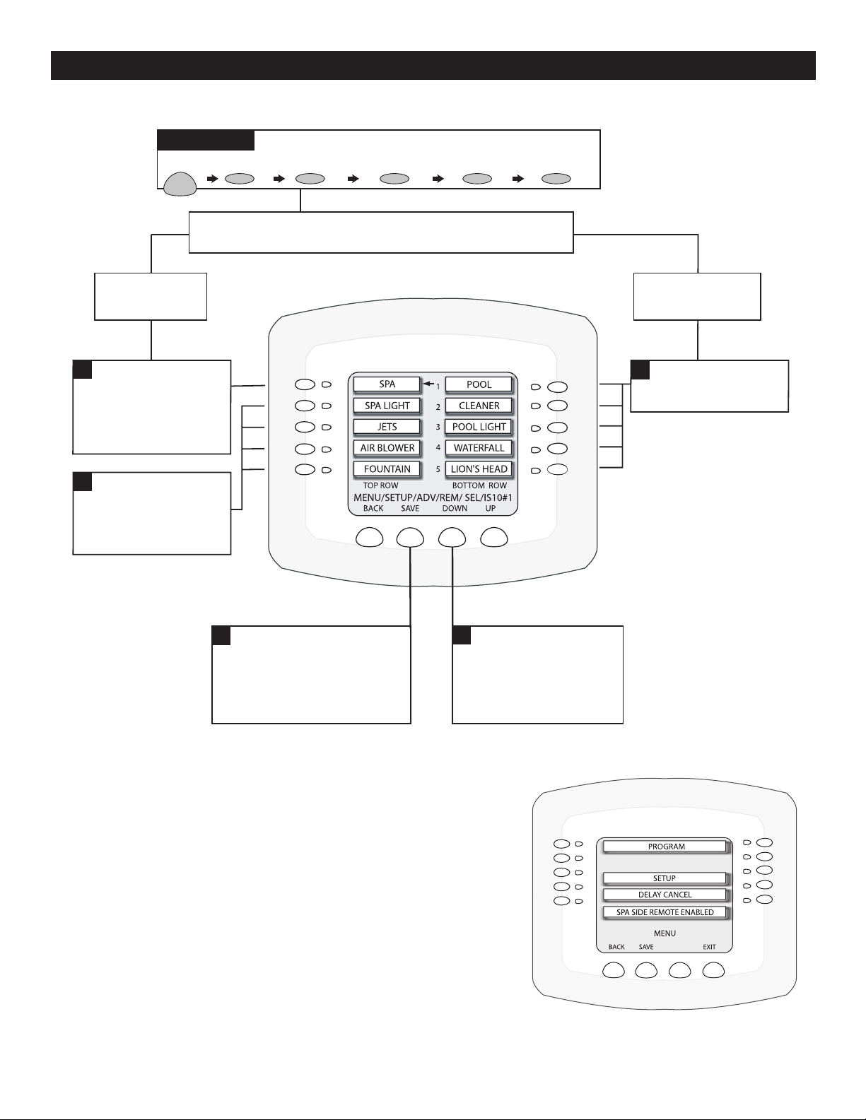
Setting up the iS10 spa-side remote from the IntelliTouch indoor control panel
The iS10 spa-side remote buttons can be configured from the IntelliTouch indoor control panel. You can configure the remote
to operate ten functions.
Getting There
MENU SETUP ADVANCED REMOTES IS10'S IS10 #1
Note: Before configuring the spa-side remote, assign names
to the AUX circuits and / or FEATURE circuits, see Owner's Manual.
Top Row
Buttons 1-5
1
To configure the first
button on your Spa-side
Remote, press the top left
button. The arrow
indicates which button
you are working on.
3
To configure the other
four buttons on your Spaside Remote, repeat the
process using the next
three buttons.
5
Press SAVE when complete.
You will be returned to the iS10
selection screen. If you have more
than one iS10 to configure, then
select iS10 # 2. Repeat process
until all iS10's are configured.
2
Use the DOWN / UP
buttons to scroll through the
circuit names and find the
circuit you would like to
assign to the Spa-side button
you are working on.
Bottom Row
Buttons 5-10
(not available on i5 or i5S)
4
Configure Bottom Row
buttons in the same way
you did Top Row buttons.
Disable/Enable the iS10 spa-side remote
This feature is useful for families with young children. It gives you an easy
way to switch off the Spa-Side Remote so it cannot affect the system. You
can enable and disable the Spa-Side Remote with the same button. Each
time the button is pressed it toggles to either DISABLED or ENABLED.
Go to Menu > Setup > Advanced > Remotes > Spa Side Remote
Disable/Enable:
1. To Disable: Press SPA SIDE REMOTE ENABLED. Screen will
immediately respond and display SPA SIDE REMOTE
DISABLED. Remote is now off.
To Enable: Press SPA SIDE REMOTE DISABLED. Screen will
immediately respond and display SPA SIDE REMOTE
ENABLED. Remote is now on.
2. Press the Exit button when finished.
iS10 Spa-Side Remote Installation Guide
Page 5
iS10 spa-side remote controller Installation
The following describes how to install the iS10 spa-side remote controller. Read through the procedure before starting. The
iS10 is splash-proof and weatherproof but is NOT submersible. The iS10 remote must be installed above the highest
sustained water level. Also, when installing the iS10 with a recessed mount, the mud-box should not be submerged below
the water level.
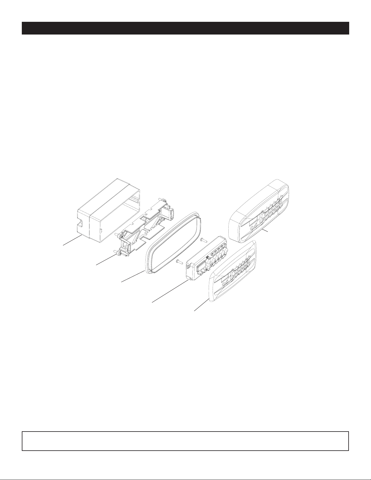
Kit Contents
The iS10 spa-side remote kit includes parts to install the iS10 remote using a recess or surface mount.
1. Two faceplates (Surface mount P/N 520355. Recess mount P/N 520354).
2. Rubber skirt ring (P/N 520443Z).
3. One bracket assembly with four screws and 0-rings (P/N 520426Z).
4. One remote assembly with two attached screws and 150 ft. of four wire 22 conductor cable (P/N 520420 for
IntelliTouch - P/N 520421 for CP3xxx)
5. Washer, flat nylon #6, Qty. 6 (P/N 520353).
6. Mud-box (P/N 520335) - Accessory not included in kit.
7. CP3xxx Adapter Kit in kit (P/N 520001).
3
Faceplate
11
1
11
Mud-box
66
6
66
(accessory)
Bracket
33
3
33
Rubber skirt ring
22
2
22
44
4
44
Remote assembly
Faceplate (Recess mount)
11
1
11
(Surface
mount)
iS10 required mounting space
In order to install the iS10 spa-side remote into the wall of a gunite spa, provision must be made while the spa is being
plumbed. For recessed mounting (even with tile, plaster, or other flat installation only), a mounting enclosure
(mud-box, P/N 520335 sold separately) and flat faceplate must be used. For surface mounting (protruding from deck, tile or
uneven surface), a skirted faceplate is used without the use of a mud-box. When installed, the iS10 remote requires the
following space:
Flat Faceplate: 6-1/2” x 3-1/2”
Skirted Faceplate: 6” x 2-5/8” x 1-1/4” high
Mud-box: 5-1/2” x 2-1/2” x 2-7/8” deep
Material: ABS plastic
Note: If the IntelliTouch load center to which the spa-side remote is connected is not located above the spa water level, a
junction box should be provided (above water level).
iS10 Spa-Side Remote Installation Guide
Page 6

4
Recess mount installation
CAUTION - The iS10 is splash-proof/weatherproof and is NOT submersible. The iS10 must be installed above the
highest sustained water level. Do not allow mud-box to be submerged.
Step 1: Install Conduit
Prepare the mounting location near the spa by
installing a 1 in. conduit where the remote control
is to be located. Conduit may be reduced down
to ¾ in. or ½ in. after the first three inches cast
into the spa area. Run the conduit from the spa
to the low voltage raceway of IntelliTouch load
center using sweep elbows for turns.
Step 2: Install Mud-Box
Slide the mud-box over the conduit. Trim the
conduit so that it just protrudes into the mud-box.
The fit will be loose. Orient the mud-box so the
iS10 spa-side remote will be even with the deck
or spa wall. Secure the mud-box and plumbing
together using NEUTRAL CURE caulking or RTV.
Insert the mud-box cover (secure with two
screws) until the deck or spa wall are finished,
discard insert when completed (keep the screws
for bracket installation). Cut away the mud-box
wall protruding from finished deck or spa wall.
iS10 remote (recessed mount)
Washers
(as needed)
Nipple
Drain tube
for "face-up"
installation
Washers
(as needed)
Mud box
Conduit
A nipple has been added to the mud-box for drainage if necessary. Cut the end of the nipple and attach a piece of ½ in.
tubing. Run the tubing to appropriate drainage location away from the remote before finishing the deck or spa wall.
Step 3: Mount the iS10 remote
Recess mount using a mud-box
1. Feed the wire into the conduit. Leave about eight inches of wire slack for installation.
2. Mount the faceplate onto the remote. Secure it with the two screws provided in the kit.
Place washers under
bracket flanges as needed
Mud-box
Bracket (snap corners off)
iS10 Spa-Side Remote Installation Guide
Screw (2x)
provided
with the
mud-box kit
Screw (2x)
Remote
Faceplate
(recess
mount)
Page 7

Recess mount installation (Continued)
Recess mount using a mud-box (Continued)
3. Snap off the four corners of the bracket where the screws holes are. Insert the bracket inside the mud-box. Be
sure that it is level. Secure the bracket to the mud-box with two screws.
4. Route the wire around the outside of the bracket as shown. Note: Wire comes out of the remote through slot A in
the bracket.
5. Place the faceplate over the bracket and press down evenly to secure in place. Be sure that the wire is not
pinched. If the remote has difficulty snapping in place, use the washers (provided in the kit) as necessary
underneath flanges to allow attachment of remote.
6. If necessary, you can “dress-up” the faceplate edges by placing a bead of NEUTRAL CURE caulking or RTV
underneath the flat faceplate around the edges.
Mud-box
5
Screw
Wire
Screw
Slot A
Faceplate
(surface mount)
Faceplate (surface mount)
Step 4: Wiring the iS10 remote
See “Wiring the iS10 remote to the IntelliTouch load center,” page 8.
iS10 Spa-Side Remote Installation Guide
Page 8

6
Surface mount installation
CAUTION - The iS10 is splash-proof/weatherproof and is NOT submersible. The iS10 must be installed above the
highest sustained water level.
Step 1: Install Conduit
Prepare the mounting location near the spa by installing a 1 in. conduit where the remote control is to be located. The
plumbing must protrude from the deck or spa wall. Conduit may be reduced down to ¾ in. or ½ in. after the first three inches
cast into the spa area. Run conduit from spa to low voltage raceway of Load Center using sweep elbows for turns. When
the deck or spa wall have been finished, carefully trim the plumbing back to be flush to the deck or spa-wall.
iS10 remote
Skirted faceplate
Rubber skirt ring
or caulk
Conduit
Step 2: Mount the iS10 remote
Surface mount installation
1. Feed the wire into the conduit. Leave about eight inches of wire slack for installation.
2. Mount the faceplate onto the remote. Secure it with the two screws provided in the kit.
Install 4
screws into
anchors
Bracket
Rubber skirt ring
Screw (2x)
Remote
Faceplate
(surface
mount)
iS10 Spa-Side Remote Installation Guide
Page 9

Surface mount installation (Continued)
Step 2: Mount the iS10 remote (Continued)
3. Drill four 3/16 inch holes in the wall or deck using the bracket template provided as a guide (see page xx). Insert
the four wall anchors provided in the kit.
4. Install the bracket on the spa wall. Be sure that it is level. Secure the bracket with the four screws.
5. Place the rubber skirt ring over the bracket.
6. Route the wire around the outside of the bracket.
Route wire through opening and
Bracket
around bracket
Rubber skirt ring
7
7. Snap on the faceplate over to remote. Press down evenly on the faceplate to secure in place.
Faceplate
Place label here
8. If the rubber skirt ring is not used: Place a bead of NEUTRAL CURE caulking or RTV underneath the
faceplate around the edges. Wipe away excess caulking and allow bonding to set.
9. Attach appropriate labels to faceplate.
Step 3: Wiring the iS10 remote
See “Wiring the iS10 remote to the IntelliTouch load center,” page 8.
iS10 Spa-Side Remote Installation Guide
Page 10

8
Wiring the iS10 remote to the IntelliTouch load center
WARNING - RISK OF ELECTRICAL SHOCK
Shut off power to system if High Voltage Cover Panel is removed.
Failure to do so could result in personal injury and/or death.
Shorting wires may permanently damage unit. Close all panels
and Load Center Door when installation is complete. Failure to do
so may damage system.
The iS10 spa-side remote is connected to the IntelliTouch system via the RS-485 four wire communication cable. For more
information about setting up the iS10 remote, refer to the IntelliTouch User's Guide (P/N 520102).
To connect the iS10 remote communication cable to IntelliTouch load center:
1. CAUTION - Switch the main power off to the IntelliTouch load center.
2. Unlatch the IntelliTouch load center front door spring latches, and open the front door.
3. Remove the cover-panel screws securing the high voltage cover-panel, and remove it from the enclosure.
4. Loosen the two control panel access screws and fold down the outdoor control panel.
5. Insert the four-wire cable into plastic grommet on the bottom of the enclosure and route the wire up through the
low voltage raceway to the Personality board.
Access screw
Personality Board
Cover-panel
screw
(Cover-panel
removed)
Low voltage raceway
Plastic grommet
iS10 Spa-Side Remote Installation Guide
IntelliTouch Load Center
Page 11

Wiring the iS10 remote to the IntelliTouch load center (Continued)
6. Strip back the iS10 remote cable jacket 1” and the cable conductors ¼”. Insert the wires into either of the
COM PORTS (J7 and J8) screw terminals located on the left side of the Personality board. Secure the wires
with the screws. Be sure that the wire color code is correct as shown on the screw terminal.
wires may be inserted into a single screw terminal.
IntelliTouch Personality
board COM ports
(J7/J8)
BLK
GRN
YEL
RED
7. Close the IntelliTouch control panel and secure it with the two access screws.
9
Note: Multiple
8. Install the high voltage panel cover and secure it with the two retaining screws.
9. Close the load center front door and secure with the two latches.
10. Switch power on to the IntelliTouch load center.
11. For iS10 remote configuration information, refer to “Adding an iS10 remote controller to IntelliTouch,” on
page 10.
iS10 Spa-Side Remote Installation Guide
Page 12

10
Adding an iS10 spa-side remote controller to IntelliTouch
Up to four iS10 Spa-Side remote controllers can be installed to allow each iS10 to operate different functions or to the same
functions at different locations. Each iS10 can be assigned as number 1, 2, 3, or 4. If a different number is not assigned to
each installed iS10, then all iS10’s are assigned as number iS1. This is useful if you wish to have the same functions
available at different iS10 locations.
The following steps describe how to manually assign each iS10 a number 2, 3, or 4 as required.
Note: If the first iS10 was installed with the main Load Center or Power Center, it will automatically be assigned as number
IS1. Other additional iS10 remotes need to be manually assigned.
To assign additional iS10 remotes as iS2, iS3, or iS4:
1. On the IntelliTouch outdoor control panel, press the Reset button then press the 1 button. The three “System
Control” LEDs will start flashing.
2. On the iS10, press the bottom part of the “peanut shaped” toggle switch and the 1 button at the same time while
the outdoor control panel LEDs are flashing.
3. The iS10 temperature display will show SHA.
4. The four red iS10 LEDs adjacent to the in-line buttons will be on. Do one of the following:
• If this is the second iS10, press 2. The temperature display reads IS2.
• If this is the third iS10, press 3. The temperature display reads IS3.
• If this is the fourth iS10, press 4. The temperature display reads IS4.
5. The iS10 red LEDs will start to flash for about a minute. Wait until they stop flashing. Repeat steps 2-4 for each
remote.
6. On the outdoor control panel, press the Reset button. The iS10 is now configured.
Note: To configure the buttons on the iS10 remote controller, refer to “Setting up the iS10 remote from IntelliTouch indoor
control panel” see page 2. To disable or enable the iS10 remote from the indoor control panel, refer to “Disable/Enable
the iS10 spa-side remote,” see page 2.
Three System
Control LEDs
Auxiliary LEDs
IntelliTouch outdoor
control panel
(Located in the load
center or power
center)
1 button
Reset button
2 button
3 button
4 button
iS10 spa-side remote
iS10 Spa-Side Remote Installation Guide
Press Toggle switch and 1 Button at the same time
Page 13

11
Adding an iS10 remote controller to a CP3xxx system
Connecting to the CP3xxx load center using the adapter
Strip back the cable 1” and ends of leads ¼ in. Open the cable adapter (P/N 520000, included in kit). Insert the iS10 spaside remote cable into the adapter and attach wires to the terminals (see the wiring diagram below). Attach the six conductor
flat cable pig-tail between cable adapter and the COM port connector on the circuit board in the load center.
iS10 WIRING
iS10 ADAPTER
RED YEL
YEL RED
GRN GRN
BLK WHT
iS10 wiring diagram
Upgrading from the SS8 to the iS10 remote
The iS10 spa-side remote may be used to replace the SS8 spa-side remote on the CP3XXX family of systems. Note: The
iS10 remote will still only control up to eight functions. The SS8 must also have been plumbed with a minimum 1-inch
conduit.
Remove SS8 remote
Unplug the SS8 from the load center then pull out the unit from spa-side location. Remove the SS8 mounting bracket from
spa-side location (two screws). All that should be left is a minimum of 1-inch. diameter conduit.
Install the iS10 remote
The installation is identical as the iS10 surface mounting of a new installation (see pages 4 through 7) except for the
faceplate (P/N 520427) to match the SS8 footprint. Run spa-side remote cable through conduit and into the load center.
Compool connector block with cables
SS8 faceplate
iS10 Spa-Side Remote Installation Guide
Page 14

12
iS10 Spa-Side Remote Installation Guide
iS10 bracket guide template
Page 15

Page 16

P/N 520208 - Rev B
 Loading...