

Page 1
INTELLIPRO® 2 VST
VARIABLE SPEED PUMP
IMPORTANT SAFETY INSTRUCTIONS
READ AND FOLLOW ALL INSTRUCTIONS
SAVE THESE INSTRUCTIONS
INSTALLATION AND
USER’S GUIDE
Page 2

i
CUSTOMER SERVICE / TECHNICAL SUPPORT
If you have questions about ordering Pentair Aquatic Systems replacement parts, and pool products, please contact:
Customer Service and Technical Support, USA
(8 A.M. to 4:30 P.M. — Eastern/Pacific Times)
Phone: (800) 831-7133
Fax: (800) 284-4151
Web site
Visit www.pentairpool.com or www.staritepool.com to
find out information about Pentair products.*
TABLE OF CONTENTS
Important Pump Warning and
Safety Instructions ................................................
Pump Overview ......................................................
Drive Assembly and Control Panel
External Control
Motor Features
Drive Features
Installation .............................................................
Location
Piping
Electrical Requirements
Optional Keypad Relocation Kit
Fittings and Valves
Electrical Installation
Wiring, Grounding and Bonding
Operating the Pump ...............................................
Priming the Pump
Using the Operator Control Panel
Stopping and Starting the Pump
Adjusting and Saving a Pump Speed
Operating the Pump at Preset Speeds
Pump Operating Modes
Control Panel: Pump Menu Guide
Pump Settings ........................................................
Set Date and Time
Set AM/PM or 24-Hour Clock
Set Min/Max Speeds
Pump Address
Set Screen Contrast
Set Control Panel Language
Set Temperature Unit
Password Protection
Setting Password
Setting Speeds 1-8 ................................................
Pump Operating Modes
Setting Speeds 1-4 in Manual Mode
Setting Speeds 1-4 in Egg Timer Mode
Setting Speeds 1-8 in Schedule Mode
Sanford, North Carolina (8 A.M. to 4:30 P.M. ET)
Phone: (919) 566-8000
Fax: (919) 566-8920
Moorpark, California (8 A.M. to 4:30 P.M. PT)
Phone: (805) 553-5000 (Ext. 5591)
Fax: (805) 553-5515
External Control ...................................................
ii
Features ................................................................
1
1
1
1
1
2
2
2
2
2
2
3
3
4
4
5
6
6
6
6
7
8
8
8
8
8
9
9
9
9
10
11
11
11
11
11
Time Out
Quick Clean
Priming ..................................................................
Priming Features
Setting Priming Features
Disabling Priming with an Automation System
Thermal Mode ......................................................
Connecting to an Automation System ................
External Control with IntelliComm
Communication Center
Connecting to EasyTouch and IntelliTouch
Systems
Connecting to SunTouch Systems
Maintenance ..........................................................
Pump Strainer Basket
Cleaning the Pump Strainer Basket
Winterizing
Servicing ...............................................................
Motor and Drive Care
Shaft Seal Replacement
Pump Disassembly
Pump Reassembly/Installing New Seal
Drive Assembly Removal and Installation
Alerts and Warnings
Troubleshooting ....................................................
Replacement Parts ...............................................
Illustrated Parts List
Pump Dimensions
Electrical Specifications
Pump Performance Curves
Operator Control Panel Quick Reference Guide
12
13
13
13
13
14
15
15
16
17
17
17
19
20
20
20
20
21
21
21
21
22
22
23
24
26
26
27
27
27
28
Compatible with IntelliComm® Communication Center and EasyTouch®, IntelliTouch® and SunTouch® Control Systems.
* Translated versions of this manual are available online at / La versión en español de este manual del producto, se puede encontrar en línea a /
La version française de ce manuel est disponible à
pump-480.htm
P/N 356890 Rev. C 6/16/16
INTELLIPRO® 2 VST Variable Speed Pump Installation and User’s Guide
: http://www.pentairpool.com/products/pumps-inground-intellipro-2-vst-variable-speed-
Page 3
IMPORTANT PUMP WARNING AND SAFETY INSTRUCTIONS
IMPORTANT NOTICE
This guide provides installation and operation instructions for this pump.
Consult Pentair with any questions regarding this equipment.
Attention Installer: This guide contains important information about the
installation, operation and safe use of this product. This information should
be given to the owner and/or operator of this equipment after installation
or left on or near the pump.
Attention User: This manual contains important information that will help
you in operating and maintaining this product. Please retain it for future
reference.
READ AND FOLLOW ALL INSTRUCTIONS
SAVE THESE INSTRUCTIONS
This is the safety alert symbol. When you see this
symbol on your system or in this manual, look for
one of the following signal words and be alert to
the potential for personal injury.
Warns about hazards that can cause death,
serious personal injury, or major property damage
if ignored.
Warns about hazards that may cause death,
serious personal injury, or major property damage
if ignored.
Warns about hazards that may or can cause minor
personal injury or property damage
if ignored.
NOTE Indicates special instructions not related to
hazards.
Carefully read and follow all safety instructions in this manual and on
equipment. Keep safety labels in good condition; replace if missing
or damaged.
When installing and using this electrical equipment, basic safety
precautions should always be followed, include the following:
Do not permit children to use this product.
RISK OF ELECTRICAL SHOCK. Connect only to
a branch circuit protected by a ground-fault circuitinterrupter (GFCI). Contact a qualified electrician if you cannot verify that
the circuit is protected by a GFCI.
This unit must be connected only to a supply circuit
that is protected by a ground-fault circuit-interrupter
(GFCI). Such a GFCI should be provided by the installer and should
be tested on a routine basis. To test the GFCI, push the test button.
The GFCI should interrupt power. Push the reset button. Power should
be restored. If the GFCI fails to operate in this manner, the GFCI is
defective. If the GFCI interrupts power to the pump without the test button
being pushed, a ground current is flowing, indicating the possibility of an
electric shock. Do not use this pump. Disconnect the pump and have the
problem corrected by a qualified service representative before using.
This pump is for use with permanent swimming
pools and may also be used with hot tubs and spas if
so marked. Do not use with storable pools. A permanently-installed pool
is constructed in or on the ground or in a building such that it cannot be
readily disassembled for storage. A storable pool is constructed so that
it is capable of being readily disassembled for storage and reassembled
to its original integrity.
ii
General Warnings
• Never open the inside of the drive motor enclosure. There is a
capacitor bank that holds a 230 VAC charge even when there is no
power to the unit.
• The pump is not submersible.
• The pump is capable of high flow rates; use caution when installing
and programming to limit pumps performance potential with old or
questionable equipment.
• Code requirements for electrical connection differ from country to
country, state to state, as well as local municipalities. Install equipment
in accordance with the National Electrical Code and all applicable
local codes and ordinances.
• Before servicing the pump; switch OFF power to the pump by
disconnecting the main circuit to the pump.
• This appliance is not intended for use by persons (including children) of
reduced physical, sensory or mental capabilities, or lack of experience
and knowledge, unless they have been given supervision or instruction
concerning the use of the appliance by a person responsible for their
safety.
FAILURE TO FOLLOW ALL INSTRUCTIONS AND
WARNINGS CAN RESULT IN SERIOUS BODILY
INJURY OR DEATH. THIS PUMP SHOULD BE INSTALLED AND
SERVICED ONLY BY A QUALIFIED POOL SERVICE PROFESSIONAL.
INSTALLERS, POOL OPERATORS AND OWNERS MUST READ THESE
WARNINGS AND ALL INSTRUCTIONS IN THE OWNER’S MANUAL
BEFORE USING THIS PUMP. THESE WARNINGS AND THE OWNER’S
MANUAL MUST BE LEFT WITH THE POOL OWNER.
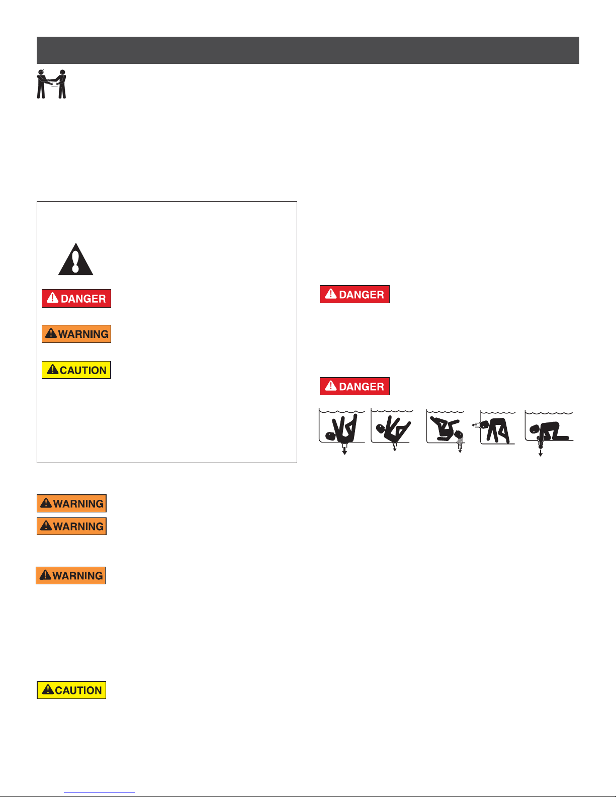
SUCTION ENTRAPMENT HAZARD: STAY OFF
THE MAIN DRAIN AND AWAY FROM ALL SUCTION
OUTLETS!
F
THIS PUMP PRODUCES HIGH LEVELS OF SUCTION AND CREATES
A STRONG VACUUM AT THE MAIN DRAIN AT THE BOTTOM OF THE
BODY OF WATER. THIS SUCTION IS SO STRONG THAT IT CAN TRAP
ADULTS OR CHILDREN UNDER WATER IF THEY COME IN CLOSE
PROXIMITY TO A DRAIN OR A LOOSE OR BROKEN DRAIN COVER
OR GRATE.
THE USE OF UNAPPROVED COVERS OR ALLOWING USE OF
THE POOL OR SPA WHEN COVERS ARE MISSING, CRACKED OR
BROKEN CAN RESULT IN BODY OR LIMB ENTRAPMENT, HAIR
ENTANGLEMENT, BODY ENTRAPMENT, EVISCERATION AND/OR
DEATH.
The suction at a drain or outlet can cause:
Limb Entrapment: When a limb is sucked or inserted into an opening
resulting in a mechanical bind or swelling. This hazard is present when
a drain cover is missing, broken, loose, cracked or not properly secured.
Hair Entanglement: When the hair tangles or knots in the drain cover,
trapping the swimmer underwater. This hazard is present when the flow
rating of the cover is too small for the pump or pumps.
Body Entrapment: When a portion of the body is held against the drain
cover trapping the swimmer underwater. This hazard is present when the
drain cover is missing, broken or the cover flow rating is not high enough
for the pump or pumps.
Evisceration/Disembowelment: When a person sits on an open pool
(particularly a child wading pool) or spa outlet and suction is applied directly
to the intestines, causing severe intestinal damage. This hazard is present
when the drain cover is missing, loose, cracked, or not properly secured.
INTELLIPRO® 2 VST Variable Speed Pump Installation and User’s Guide
Page 4
iii
IMPORTANT PUMP WARNING AND SAFETY INSTRUCTIONS
Mechanical Entrapment: When jewelry, swimsuit, hair decorations,
finger, toe or knuckle is caught in an opening of an outlet or drain cover.
This hazard is present when the drain cover is missing, broken, loose,
cracked, or not properly secured.
NOTE: ALL SUCTION PLUMBING MUST BE INSTALLED IN
ACCORDANCE WITH THE LATEST NATIONAL AND LOCAL CODES,
STANDARDS AND GUIDELINES.
TO MINIMIZE THE RISK OF INJURY DUE TO
SUCTION ENTRAPMENT HAZARD:
• A properly installed and secured ANSI/ASME A112.19.8 approved
anti-entrapment suction cover must be used for each drain.
• Each suction cover must be installed at least three (3’) feet apart,
as measured from the nearest point to nearest point.
• Regularly inspect all covers for cracks, damage and advanced
weathering.
• If a cover becomes loose, cracked, damaged, broken or is missing,
replace with an appropriate certified cover.
• Replace drain covers as necessary. Drain covers deteriorate over
time due to exposure to sunlight and weather.
• Avoid getting hair, limbs or body in close proximity to any suction
cover, pool drain or outlet.
• Disable suction outlets or reconfigure into return inlets.
A clearly labeled emergency shut-off switch for the
pump must be in an easily accessible, obvious place.
Make sure users know where it is and how to use it in case of emergency.
The Virginia Graeme Baker (VGB) Pool and Spa Safety Act creates
new requirements for owners and operators of commercial swimming
pools and spas.
Commercial pools or spas constructed on or after December 19, 2008,
shall utilize:
(A) A multiple main drain system without isolation capability with suction
outlet covers that meet ASME/ANSI A112.19.8a Suction Fittings for
Use in Swimming Pools, Wading Pools, Spas, and Hot Tubs and either:
(i) A safety vacuum release system (SVRS) meeting ASME/ANSI
A112.19.17 Manufactured Safety Vacuum Release systems (SVRS)
for Residential and Commercial Swimming Pool, Spa, Hot Tub,
and Wading Pool Suction Systems and/or ASTM F2387 Standard
Specification for Manufactured Safety Vacuum Release Systems
(SVRS) for Swimming pools, Spas and Hot Tubs or
(ii) A properly designed and tested suction-limiting vent system or
(iii) An automatic pump shut-off system.
Commercial pools and spas constructed prior to December 19, 2008,
with a single submerged suction outlet shall use a suction outlet cover
that meets ASME/ANSI A112.19.8a and either:
(A) A SVRS meeting ASME/ANSI A112.19.17 and/or ASTM F2387, or
(B) A properly designed and tested suction-limiting vent system, or
(C) An automatic pump shut-off system, or
(D) Disabled submerged outlets, or
(E) Suction outlets shall be reconfigured into return inlets.
For Installation of Electrical Controls at Equipment Pad (ON/OFF
Switches, Timers and Automation Load Center)
Install all electrical controls at equipment pad, such as
on/off switches, timers, and control systems, etc. to
allow the operation (startup, shut-down, or servicing)
of any pump or filter so the user does not place any
portion of his/her body over or near the pump strainer
lid, filter lid or valve closures. This installation should
allow the user enough space to stand clear of the
filter and pump during system start-up, shut down or
servicing of the system filter.
INTELLIPRO® 2 VST Variable Speed Pump Installation and User’s Guide
HAZARDOUS PRESSURE: STAND CLEAR OF
PUMP AND FILTER DURING START UP
Circulation systems operate under high pressure.
When any part of the circulating system (i.e.
locking ring, pump, filter, valves, etc.) is serviced,
air can enter the system and become pressurized.
Pressurized air can cause the pump housing cover, filter lid, and valves
to violently separate which can result in severe personal injury or death.
Filter tank lid and strainer cover must be properly secured to prevent
violent separation. Stand clear of all circulation system equipment when
turning on or starting up pump.
Before servicing equipment, make note of the filter pressure. Be sure
that all controls are set to ensure the system cannot inadvertently start
during service. Turn off all power to the pump. IMPORTANT: Place filter
manual air relief valve in the open position and wait for all pressure
in the system to be relieved.
Before starting the system, fully open the manual air relief valve and place
all system valves in the “open” position to allow water to flow freely from the
tank and back to the tank. Stand clear of all equipment and start the pump.
IMPORTANT: Do not close filter manual air relief valve until all
pressure has been discharged from the valve and a steady stream
of water appears. Observe filter pressure gauge and be sure it is not
higher than the pre-service condition.
General Installation Information
• All work must be performed by a qualified service professional, and
must conform to all national, state, and local codes.
• Install to provide drainage of compartment for electrical components.
• These instructions contain information for a variety of pump models
and therefore some instructions may not apply to a specific model. All
models are intended for use in swimming pool applications. The pump
will function correctly only if it is properly sized to the specific application
and properly installed.
Pumps improperly sized or installed or used in
applications other than for which the pump was
intended can result in severe personal injury or death. These risks may
include but not be limited to electric shock, fire, flooding, suction
entrapment or severe injury or property damage caused by a structural
failure of the pump or other system component.
The pump can produce high levels of suction within
the suction side of the plumbing system. These high
levels of suction can pose a risk if a person comes within the close
proximity of the suction openings. A person can be seriously injured by
this high level of vacuum or may become trapped and drown. It is
absolutely critical that the suction plumbing be installed in accordance
with the latest national and local codes for swimming pools.
Warnings and safety instructions for Pentair Aquatic Systems
pumps and other related products are available at:
http://www.pentairpool.com/pool-owner/safety-warnings/ or call
(800) 831-7133 for additional free copies of these instructions.
Please refer to http://www.pentairpool.com/pool-owner/
safetywarnings/ for warning and safety instructions related to the
this product.
SAVE THESE INSTRUCTIONS
Warning Page P/N 352557 Rev. A 6/15
Page 5
1
PUMP OVERVIEW
The IntelliPro® 2 VST Variable Speed Pump can
be programmed to run at specific speeds and time
intervals for maximum operating efficiency and energy
conservation for a variety of inground pools.
• The pump can operate from 450 RPM to 3450 RPM
with four preset speeds of 750, 1500, 2350 and 3110
RPM
• The pump can be adjusted from the control panel to
run at any speed between 450 RPM to 3450 RPM
for different applications
• Up to 8 programmable speeds
• Pump control panel alarm LED and error messages
warn the user against under and over voltage, high
temperature, over current and freeze protection
• Communicates with EasyTouch
®
, IntelliTouch® or
SunTouch® Control Systems or an IntelliComm®
Communication Center via a two-wire RS-485
cable connection
• Self-priming for easy start-up
• Compatible with most cleaning systems, filters, and
jet action spas
• UL/CUL/NSF Listed
Drive Assembly and Control Panel
The IntelliPro 2 VST pump drive is designed to produce
maximum motor operational efficiency. The drive
controls the motor’s rotational speed by controlling the
frequency of the supplied current. It also protects the
motor and pump from operating outside of their intended
operating parameters.
The control panel can be mounted on the pump in four
different directions in order to provide the user the best
access. The control panel can also be mounted in a
more convenient location with the help of the keypad
relocation kit.
External Control
IntelliTouch®, EasyTouch®, SunTouch® Control Systems and
IntelliComm
IntelliPro 2 VST pump. The pump’s communications address
and other functions are accessible from the pump’s control
panel.
• RS-485 commincation cable included
• IntelliTouch systems control 8 IntelliPro pumps using 8
speeds per pump.
• EasyTouch
speeds per pump.
• SunTouch systems control one IntelliPro pump using 8
speeds.
• IntelliComm systems control one IntelliPro pump using
the 4 External Control programs.
®
Communication Centers can remotely control the
systems control 2 IntelliPro pumps using 8
Motor Features
• Permanent Magnet Synchronous Motor (PMSM)
• High efficiency (3450 RPM 92% and 1000 RPM 90%)
• Superior speed control
• Operates at lower temperatures due to high efficiency
• Designed to withstand outdoor environment
• Totally Enclosed Fan Cooled (TEFC) Motor, IPX5
Rated
• Three-phase motor
• 56 Square Flange
• Low noise
Drive Features
• Active Power Factor Correction
• UL 60730 Compliant
• Rotatable Keypad
• Easy Overhead Wiring
• High Drive Operational Efficiency
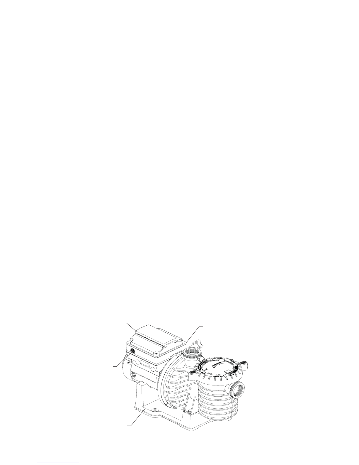
Operator Control Panel Cover
(Buttons and LED Beneath)
AC Power Connection
Compartment
Motor Stand
IntelliPro 2 VST Variable Speed Drive Assembly
Communication port for connection to
EasyTouch, IntelliTouch or SunTouch
control system or IntelliComm
communication center via two-wire
RS-485 cable (not shown)
INTELLIPRO® 2 VST Variable Speed Pump Installation and User’s Guide
Page 6
2
INSTALLATION
Only a qualified plumbing professional should install the IntelliPro® 2 VST Variable Speed Pump. Refer to “Important
Pump Warning And Safety Instructions” on pages ii - iii for additional installation and safety information.
Location
Note: Do not install this pump within an outer enclosure or
beneath the skirt of a hot tub or spa unless marked accordingly.
Note: Ensure that the pump is mechanically secured to the
equipment pad.
Be sure the pump location meets the following
requirements:
1. Install the pump as close to the pool or spa as possible.
To reduce friction loss and improve efficiency, use short,
direct suction and return piping.
2. Install a minimum of 5 feet (1.52 meters) from the inside
wall of the pool and spa. Canadian installations require
a minimum of 9.8 feet (3 meters) from the inside wall of
the pool.
3. Install the pump a minimum of 3 feet (.9 meters) from the
heater outlet.
4. Do not install the pump more than 10 feet (3.1 meters)
above the water level.
5. Install pump in a well ventilated location protected from
excess moisture (i.e. rain gutter downspouts, sprinklers,
etc.).
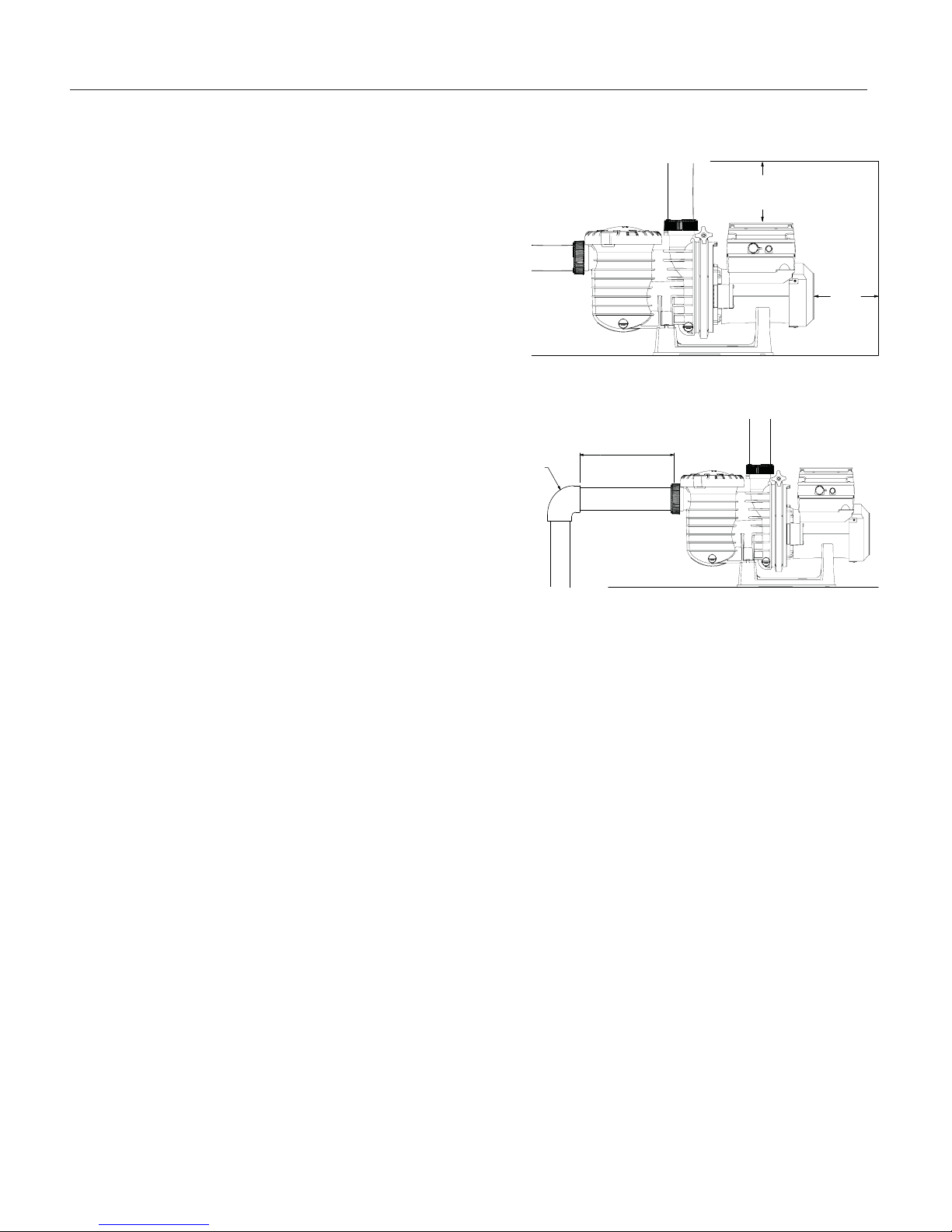
6. Install the pump with a rear clearance of at least 3 inches
(7.6 cm) so that the motor can be removed easily for
maintenance and repair. See Figure 1.
Figure 1: Pump Rear and Overhead Clearance
MIN 5 X SUCTION PIPE DIAMETER
ELBOW
Figure 2: Recommended Piping
6 IN.
(15.2 CM)
MINIMUM
3 IN.
(7.6 CM)
MINIMUM
Piping
1. For improved pool plumbing, it is recommended to use a
larger pipe size. When installing the inlet and outlet fittings
(male adaptors), unless using the unions supplied with the
pump, use thread sealant.
2. Piping on the suction side of the pump should be the same
or larger than the return line diameter.
3. Plumbing on the suction side of the pump should be as
short as possible.
4. For most installations Pentair recommends installing a
valve on both the pump suction and return lines so that
the pump can be isolated during routine maintenance.
We also recommend a valve, elbow or tee installed in the
suction line should be no closer to the front of he pump
than five (5) times the suction line pipe diameter. See
Figure 2.
Example: A 2.5 inch pipe requires a 12.5 inch (31.8 cm)
straight run in front of the suction inlet of the pump). This
will help the pump prime faster and last longer.
Note: DO NOT install 90° elbows directly into the pump
inlet and outlet.
Electrical Requirements
• Install all equipment in accordance with the National
Electrical Code and all applicable local codes and
ordinances.
• A means for disconnection must be incorporated in the
fixed wiring in accordance with the wiring rules.
INTELLIPRO® 2 VST Variable Speed Pump Installation and User’s Guide
Optional Keypad Relocation Kit
In special cases when the user lacks easy or
convenient access to the IntelliPro 2 VST Variable
Speed Pump, a Keypad Relocation Kit (P/N 356905Z)
may be purchased from your local pool equipment
supplier. This kit allows the user to remove the keypad
from the top of the drive and mount the keypad in a
fixed location with better access.
For installation instructions refer to the Keypad
Relocation Kit Installation Instructions provided with
the kit.
Fittings and Valves
1. Do not install 90° elbows directly into pump inlet.
2. Flooded suction systems should have gate
valves installed on suction and discharge pipes
for maintenance, however, the suction gate valve
should be no closer than five times the suction
pipe diameter as described in this section.
3. Use a check valve in the discharge line when
using this pump for any application where there is
significant height to the plumbing after the pump.
4. Be sure to install check valves when plumbing in
parallel with another pump. This helps prevent
reverse rotation of the impeller and motor.
Page 7
3
Electrical Installation
RISK OF ELECTRICAL SHOCK OR ELECTROCUTION. This pump must be installed by a licensed or certified electrician or
a qualified service professional in accordance with the National Electrical Code and all applicable local codes and ordinances.
Improper installation will create an electrical hazard which could result in death or serious injury to users, installers, or others
due to electrical shock, and may also cause damage to property.
Always disconnect power to the pump at the circuit breaker before servicing the pump. Failure to do so could result in
death or serious injury to service people, users or others due to electric shock.
Read all servicing instructions before working on the pump.
Note: ALWAYS reinstall the drive lid onto the field wiring compartment when leaving the pump unsupervised during
servicing. This will prevent foreign matter (i.e. rainwater, dust, etc.) from accumulating in the drive.
Note: When connecting the pump to an automation system (IntelliTouch
and IntelliComm® Communication Center), continuous power must be supplied to the pump by connecting it directly
to the circuit breaker. When using an automation system, be sure that no other lights or appliances are on the same
circuit.
®
, EasyTouch®, SunTouch® Control Systems
Wiring
1. Be sure all electrical breakers and switches are turned
off before wiring motor.
STORED CHARGE - Wait at least sixty (60)
seconds before servicing.
2. Be sure that the supply voltage meets the requirements
listed on the motor nameplate. If these requirements
are not met, permanent motor damage may occur.
3. For wiring sizes and general guidelines for proper
electrical installation, please follow the specifications
defined in the National Electric Code and any local
codes as required.
4. Use strain relief and be sure all electrical connections
are clean and tight.
5. Cut the wires to the appropriate length so they do
not overlap or touch when connected.
6. Reinstall the keypad after wiring the pump by plugging
the cover back into the drive wiring connection and
re-seating the keypad in the desired orientation with
the four (4) corner screws.
Note: Ensure that the keypad cable is not pinched
between the drive and keypad during re-seating.
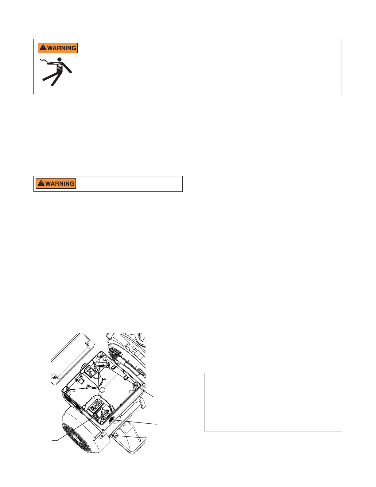
Grounding
1. Permanently ground the motor using the green ground
screw, as shown below. Use the correct wire size
and type specified by National Electrical Code. Be
sure the ground wire is connected to an electrical
service ground.
2. The pump should be permanently connected to either
a circuit breaker, 2-pole timer or 2-pole relay. If AC
power is supplied by a GFCI circuit breaker, use a
dedicated circuit breaker that has no other electrical
loads.
Bonding
1. Bond the motor to the structure in accordance with the
National Electrical Code. Use a solid copper bonding
conductor not smaller than 8 AWG. For Canadian
installations, a 6 AWG or larger solid copper bonding
conductor is required. Run a wire from the external
bonding screw or lug to the bonding structure.
2. Connect the wire from the accessible bonding lug
on the motor to all metal parts of the swimming
pool, spa, or hot tub structure and to all electrical
equipment, metal conduit, and metal piping within 5
feet (1.52 meters) of the inside walls of the swimming
pool, spa, or hot tub. Run a wire from the external
bonding screw or lug to the bonding structure.
Ground Wire
Connection
(Green Screw)
Field Wiring Compartment
Drive Wiring
Connection
1/2” NPD
Conduit Port
Bonding Lug
INTELLIPRO® 2 VST Variable Speed Pump Installation and User’s Guide
Note: When the pump is started and stopped by
removing power with a relay or timer, a two-pole
device should be used to apply and remove power to
both POWER LINE TERMINALS.
Pentair offers 2-Pole 20 Amp GFCI breakers (P/N
PA220GF) which offer 6 milliamp personnel protection
while meeting 2008 to current NEC Standards for Pool
Pumps.
Page 8
4
OPERATING THE PUMP
NOTE: Speed 1 is the default filtration speed.
NOTE: When setting up the IntelliPro
an operation schedule by following the steps in this manual. Please refer to user’s guide sections: ‘Set Time’ (page 8) and ‘Set
Speeds 1-8 in Schedule Mode’ (page 12) to schedule a time to run the pump.
This pump is shipped with Priming mode ENABLED. Unless the Priming settings are changed in the menu, be aware
that the pump will speed up to the maximum speed when the pump is powered on for the first time, and the
Start/Stop button is pressed. To change the maximum speed of the pump, refer to page 8.
Before turning the pump ON, be sure the following conditions are met:
1. Open filter air relief valve.
2. Open valves.
3. Pool return is completely open and clear of any blockages.
4. Water in the pump basket.
5. Stand clear of the filter or other pressurized vessels.
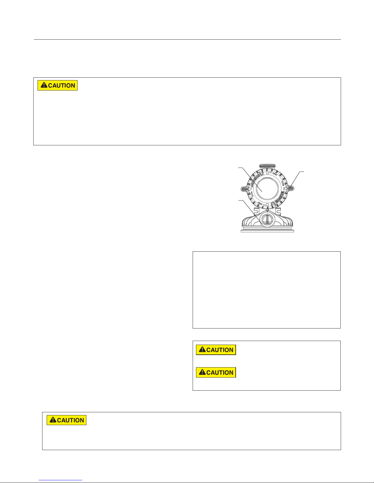
Priming the Pump
Prime the pump before starting the pump for the first time.
To avoid permanent damage to the pump, remove the lid
and fill the basket with water. The pump basket must be
filled with water before initial start up or after servicing.
®
2 VST Variable Speed Pump, the user must set the pump’s internal clock and establish
Lid
Clamp
Follow the steps below to prime the pump for start up:
1. Press Start/Stop to stop the pump. Disconnect the
pump main power supply and communication cable.
2. Close all gate valves in suction and discharge
pipes. Relieve all pressure from the system.
3. Remove the pump clamp and lid.
4. Fill the pump strainer pot with water.
5. Reassemble the pump clamp and lid onto the
strainer basket. The pump is now ready to prime.
6. Open all valves in suction and discharge pipes.
7. Open the filter air relief valve and stand clear of
the filter.
8. Connect power to the pump. Be sure green power
light is on.
9. Press Start/Stop to start the pump. The pump will
enter into priming mode (if enabled) and speed
up to the maximum speed set in the pump menu
settings.
10. When water comes out of the filter air relief valve,
close the valve. The system should now be free of
air and recirculating water to and from the pool
11. Do not allow your pump to run longer than 30
minutes time without developing full w. If the pump
does not prime, check your priming settings on the
control panel or see the “Troubleshooting” section
on pages 24-25.
Volute
Top View
Priming Features
The default priming setting is ENABLED.
The pump also allows you to set the following from
the operator control panel:
• Priming speed
• Priming range (1-10)
• Priming delay
Set up instructions on page 15.
Do not add chemicals to the system directly in
front of pump suction. Adding undiluted chemicals
may damage the pump and will void the warranty.
This is a variable speed pump. Typically the lower
speeds are used for filtration and heating. The
higher speeds can be used for spa jets, water features, and priming.
DO NOT run the pump dry. If the pump is run dry, the mechanical seal will be damaged and the pump will start leaking. If this
occurs, the damaged seal must be replaced. ALWAYS maintain proper water level in your pool (half way up skimmer opening).
If the water level falls below the skimmer opening, the pump will draw air through the skimmer, losing the prime and causing the pump to run dry,
resulting in a damaged seal. Continued operation in this manner could cause a loss of pressure, resulting in damage to the pump case, impeller and
seal and may cause property damage and personal injury.
INTELLIPRO® 2 VST Variable Speed Pump Installation and User’s Guide
Page 9
Using the Operator Control Panel
Use the operator control panel to start and stop the IntelliPro® 2
VST Variable Speed Pump, program, set, and change speeds
(RPM), and access pump features and settings.
5
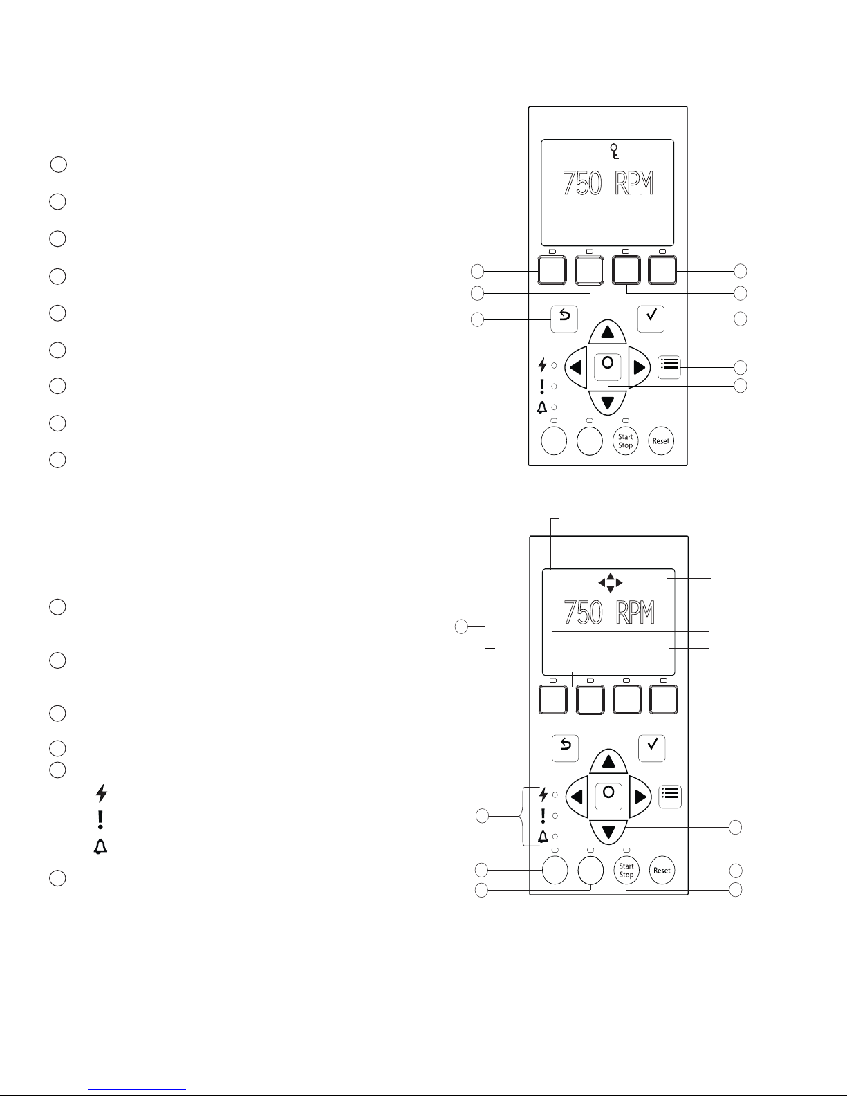
Controls and LEDs on Keypad:
Button 1: Press to select Speed 1 (750 RPM). LED on
1
indicates Speed 1 is active.
2
Button 2: Press to select Speed 2 (1500 RPM). LED on
indicates Speed 2 is active.
Button 3: Press to select Speed 3 (2350 RPM). LED on
3
indicates Speed 3 is active.
Button 4: Press to select Speed 4 (3110 RPM). LED on
4
indicates Speed 4 is active.
5
Back: Goes one step back in menu; exits without saving
current setting.
6
Save: Saves current menu item setting. When a parameter
has been adjusted the "Save?" icon will be displayed.
7
Menu: Accesses the menu items when and if the pump is
stopped.
8
Select: Press to select the currently displayed option on the
screen.
9
Arrow buttons:
• Up arrow: Move one level up in the menu or increase
a digit when editing a setting.
• Down arrow: Move one level down in the menu or
decrease a digit when editing a setting.
• Left arrow: Move cursor left one digit when editing a
setting.
• Right arrow: Move cursor right one digit when editing
a setting.
10
Quick Clean: Pump increases to a higher RPM for
vacuuming, cleaning, adding chemicals, and after a storm for
extra skimmer power. LED light is on when active.
11
Time Out: Pump is not running on preset schedule. This can
be used to allow newly glued pipe joints time to dry before
circulation of water starts. LED is on when active.
12
Start/Stop button: To start or stop the pump. When LED is
on, the pump is running or in a mode to start automatically.
13
Reset button: Reset alarm or alert.
14
LEDs:
On: Green light when pump is powered on.
Warning: On if warning condition is present.
Alarm: Red LED on if alarm condition occurs.
See “Alerts and Warnings” on page 23.
15
Control Panel LCD Screen:
• Line 1: Key icon indicates password protect mode is
active. If password protect is not enabled, no key icon is
displayed. Also shows current time of day. Active cursors
display when arrow key input is available.
• Line 2: Displays current pump speed (RPM).
• Line 3: Countdown time and watts
• Line 4: Current pump status and current feature. "Save?"
will display on this line when a parameter adjustment
can be saved.
12:15p
750 RPM
T 0.00 150 WATTS
Running Speed 1
1
2
5
Line 1
Line 2
15
Line 3
Line 4
14
10
11
Note: Always close the keypad cover after using
the keypad.
Note: Using screwdrivers or pens to program the
pump will damage the keypad overlay. Use your
fingers only when programming the pump.
1 2 3 4
SaveBack
Select
Time
Quick
Out
Clean
Control Panel #1-8
Key Lockout Icon
Menu
12:15p
750 RPM
T 0.00 150 WATTS
Running Speed 1
1 2 3
Select
Time
Quick
Out
Clean
Control Panel #9-15
Save?
4
SaveBack
Active Cursors
Current Time
Current Speed
Countdown Time
Current Power Usage
"Save?" Icon
Current Running
Feature
Menu
9
13
12
4
3
6
7
8
INTELLIPRO® 2 VST Variable Speed Pump Installation and User’s Guide
Page 10

6
Stopping and Starting the Pump
Starting the Pump
1. Be sure the pump is powered on and the green
power LED is on.
2. Select one of the speed buttons, then press the
Start/Stop button (LED on) to start the pump. The
pump will go into priming mode if priming feature
is enabled.
Stopping the Pump
1. Press Start/Stop to stop the pump.
When servicing equipment (filters, heaters, chlorinators
etc.), disconnect the communication cable, and switch
OFF circuit breaker to remove power from the pump.
Note: The pump can automatically restart if the
communication cable is connected.
Adjusting and Saving a Pump Speed
1. While the pump is running, press the Up or Down
arrow to adjust to desired speed setting.
2. Press and hold down a Speed button (1-4) for three
(3) seconds to save speed to the button or press
Save to save the speed.
Operating the Pump at Preset Speeds
The pump is programmed with four default speeds of
750, 1500, 2350 and 3110 RPM. Speed buttons 1-4 are
for each of the preset speeds as shown below.
1. Be sure the pump is powered on and the green
power LED is on.
2. Press the Speed button (1- 4) corresponding to
the desired preset speed and release quickly. The
LED above the button will turn on.
3. Press Start/Stop. The pump will quickly change to
the selected preset speed.
LED lit
1 2 3
4
Speed 1 (1-4)
Speed 5 (5-8)
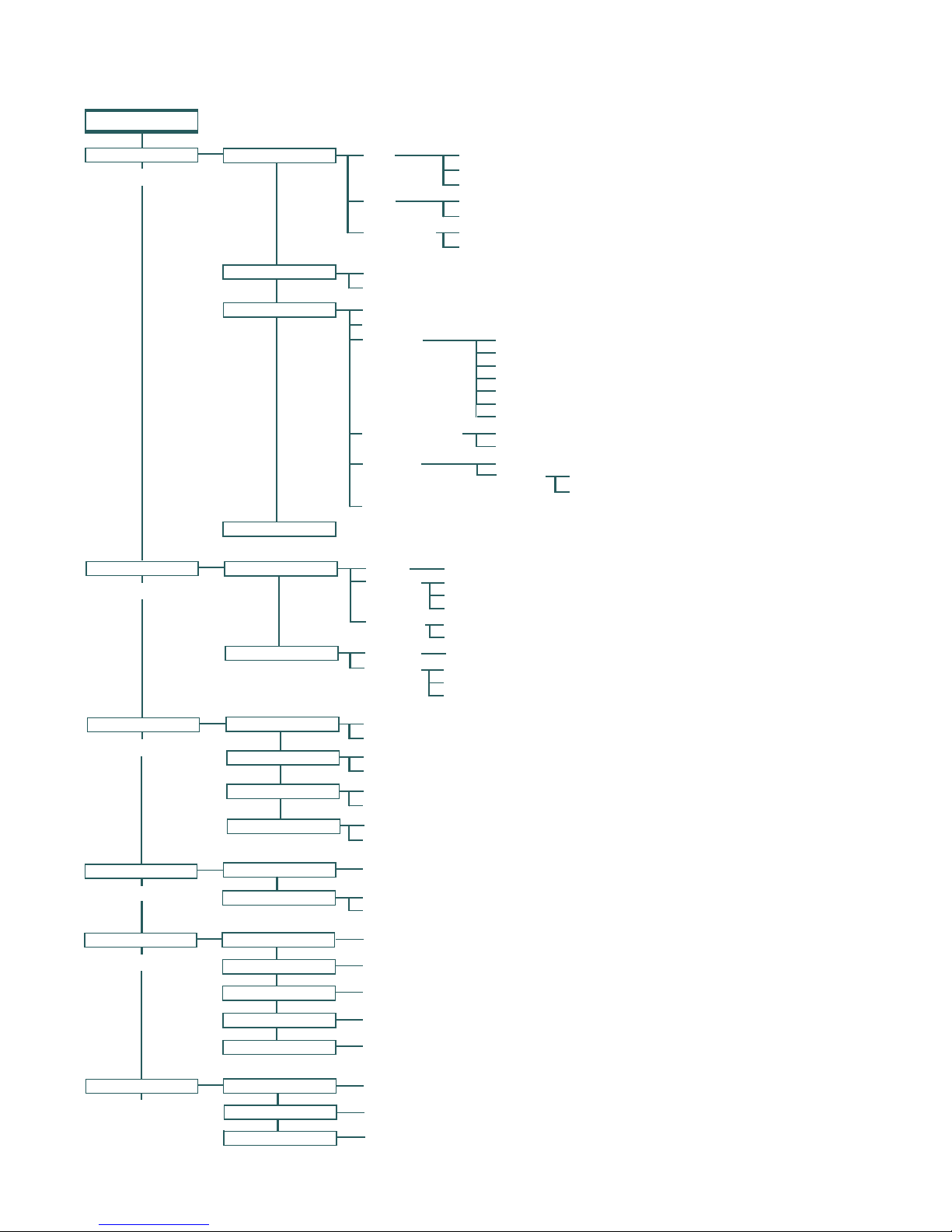
Speed Menu Tree Options
Manual
Schedule
Egg Timer
Disabled
Schedule
Set Speed - Defa
Set Speed
Set Start Time
Set Stop Time
Set Speed
Time
Default: Disabled
Set Speed
Set Start Time
Set Stop Time
Manual
Assigns a speed to one of the four Speed buttons
on the control panel. This mode can only be used
for speeds 1-4. Speeds 1 and 2 are Manual by
default.
To operate in Manual mode, press one of the four
speed buttons and then press the Start/Stop
button. The pump will run the assigned speed for
that speed button.
Egg Timer
Speeds 1-4 can be programmed to run for a
duration of time once a speed button is pressed.
Speeds 3 and 4 are Egg Timers by default. This
prevents the pump from running at a speed higher
than half of the maximum speed indefinitely. If
you desire a different method of operation, speeds
3 and 4 can be changed to Manual mode in the
control menu.
To operate in Egg Timer mode, press a speed
button and then press Start/Stop. The pump will
run that speed for the set amount of time and then
turn off.
Schedule
Program speeds 1-8 start and stop at a specific
time during a 24 hour period. Speeds programmed
in Schedule mode will override any manually
selected speed once the next Schedule command
commences.
Pump Operating Modes
The IntelliPro® 2 VST Variable Speed Pump can be
programmed in three different modes:
Manual, Schedule, and Egg Timer.
Speeds 1-4 can be programmed in all three modes.
Speeds 5-8 can only be programmed in Schedule mode
since there are no buttons on the control panel for Speeds
5-8. The default setting for Speeds 5-8 is “Disabled”.
INTELLIPRO® 2 VST Variable Speed Pump Installation and User’s Guide
Page 11
Operator Control Panel: Pump Menu Guide
7
MENU
SETTINGS
(pages 8-10)
SPEED 1-8
(pages 10-12)
Press MENU button to access menus
Set Date and Time
Set Speed Max/Min
Device
Alarm Log (1-10)
Speed 1-4
Speed 5-8
Date
Time
Hour Format
Min Speed (450-1700 RPM) - Default: 450 RPM
Max Speed (1900-3450 RPM) - Default: 3450 RPM
Pump Address (1-16) - Default: 1
Screen Contrast (1-5) - Default: 3
Language
Temperature Unit Fahrenheit - Default F°
Password
Firmware Version
Manual
Schedule
Egg Timer
Disabled
Schedule
Months (1-12)
Days (1-31)
Years (2000-2050 Plus)
Hours (24hr Mode: 0-23) (12hr Mode: 1-12 AM & PM)
Minutes (0-60)
AM/PM - Default: AM/PM
24 Hour
English - Default: English
Português
Deutsch
Italiano
Nederlands
Español
Français
Celsius C°
Disabled - Default: Disabled
Enabled
Set Speed - Default Spd 1-2: Manual
Set Speed
Set Start Time
Set Stop Time
Set Speed - Default Spd 3-4: Egg Timer
Time
Default: Disabled
Set Speed
Set Start Time
Set Stop Time
Password Timeout (1 min. to 6 hrs.) - Default: 1 minute
Set Password (0000 - 9999) - Default: 1234
EXT CONTROL
(page 12)
FEATURES
(page 13)
PRIMING
(pages 13-15)
THERMAL MODE
(page 16)
Program 1
Program 2
Program 3
Program 4
Time Out
Quick Clean
Disabled/Enabled
Priming Speed
Max Priming Time
Priming Range
Priming Delay
Disabled/Enabled
Set Speed
Pump Temperature
Set Speed (450-3450 RPM) - Default: 750 RPM
Stop Delay (0 min. to 10 min.) Default: 0 minutes
Set Speed (450-3450 RPM) - Default: 1500 RPM
Stop Delay (0 min. to 10 min.) Default: 0 minutes
Set Speed (450-3450 RPM) - Default: 2350 RPM
Stop Delay (0 min. to 10 min.) Default: 0 minutes
Set Speed (450-3450 RPM) - Default: 3110 RPM
Stop Delay (0 min. to 10 min.) Default: 0 minutes
Time Out Duration (1 min. to 10 hrs.) Default: 3 hours
Set Speed (450-3450 RPM) Default: 3450 RPM
Quick Clean Duration (1 min. to 10 hrs.) Default: 10 minutes
Disabled / Enabled - Default: Enabled
Set Speed (2400-3450 RPM) - Default: 3450 RPM
(1 min. to 30 min.) Default: 11 minutes
(1 - 10) Default: 5
(1 sec. to 10 min.) Default: 20 seconds
Disabled / Enabled - Default: Enabled
Set Speed (450 RPM - 3450 RPM) Default 1000 RPM
40° F - 50° F (4.4° C through 10° C) Default: 40° F (4.4° C)
INTELLIPRO® 2 VST Variable Speed Pump Installation and User’s Guide
Page 12

8
MENU
SETTINGS
Pump Menu: Settings
7. Press the Up or Down arrows to change the minimum
speed setting from 450 to 1700 RPM.
8. Press Save to save. To cancel, press Back to exit edit
mode without saving.
Set Date and Time
The time controls all scheduled times, functions, and
programmed cycles and stores the correct time for up
to 96 hours after power is turned off. Reset if the power
is off longer than 96 hours.
1. Check that the green power LED is on.
2. Press Menu.
3. Press Select to select “Settings”.
4. Use the Up or Down arrows to scroll to “Date and
Time” and press Select.
5. Press Select again and use Up or Down arrows to
set the date.
6. Press Save to save user input and return to "Date
and Time."
7. Use the Up or Down arrows to scroll to “Time” and
press Select.
8. Use the Up or Down arrows to scroll to set the time.
Note: To set AM/PM or a 24 hour clock see the next
section "Set AM/PM or 24 Hour Clock."
9. Press Save to save. To cancel any changes, press
Back to exit without saving.
10. Press Back to exit.
9. Press Back to exit.
Set Maximum Speed (RPM)
The maximum speed can be set from 1900 RPM to 3450
RPM (default is 3450). Use this setting to set the maximum
running speed of the IntelliPro
Pump.
1. Check that the green power LED is on.
2. Press Menu.
3. Press Select to select “Settings”.
4. Use the Up or Down arrows to scroll to “Min/Max”.
5. Use the Up or Down arrows to scroll to “Set Max Spd”.
6. Press Select to change. The cursor will appear in the
first number column (ones).
7. Press Up or Down arrows to change the maximum
speed setting from 1900 to 3450 RPM.
8. Press Save to save. Press Back to exit. To cancel, press
the Back to exit without saving.
Note: Maximum Speed will limit Priming Speed, except
in one case. If the Maximum Speed is set below the
lowest available Priming Speed (2400 RPM) then the
pump will exceed the Maximum Speed while the priming
®
2 VST Variable Speed
feature is running. This prevents the pump from having
Set AM/PM or 24-Hour Clock
To change the time from a 12 hour clock (AM/PM) to a
24 hour clock:
trouble priming if the Maximum Speed is set this low. If
this is a problem, priming can be disabled in the Priming
Menu (see “Priming” section on page 13).
1. Press Menu.
2. Press Select to select “Settings”.
3. Use the Up or Down arrows to scroll to “Date and
Time" and press Select.
4. Use the Up or Down arrows to scroll to "AM/PM"
and press Select.
5. Use the Up or Down arrows to scroll to choose
between 24 hr. and AM/PM.
6. Press Save to save. To cancel any changes, press
Back to exit without saving.
7. Press Back to exit.
Set Minimum Speed (RPM)
The minimum pump speed can be set from 450 RPM
to 1700 RPM. The default setting is 450 RPM.
1. Check that the green power LED is on.
2. Press Menu.
3. Press Select to select “Settings”.
4. Use the Up or Down arrows to scroll to “Min/Max”.
5. Use the Up or Down arrows to scroll to “Set Min Spd”.
6. Press Select to change the setting. The cursor will
Pump Address
The default pump address is #1 and only needs to be
changed when there is more than one pump on an
automation system. Change the address to allow the
automation system to send a command to the correct
pump.
Use this setting if your pump is connected via the RS-485
COM port to an IntelliTouch
Control System or IntelliComm® Communication Center.
For EasyTouch, SunTouch or IntelliComm systems, the
pump only communicates with address #1. The pump
address can be set from 1-16. The IntelliTouch
can communicate to only four (1-4) pumps.
Note: IntelliPro 2 VST pumps cannot be connected in
series with other pumps.
1. Check that the green power LED is on and the pump
is stopped.
2. Press Menu.
3. Press Select to select “Settings”.
4. Use the Up or Down arrows to scroll to “Device” and
press Select.
®
, EasyTouch®, SunTouch
system
®
appear in the first number column (ones).
INTELLIPRO® 2 VST Variable Speed Pump Installation and User’s Guide
Page 13

MENU
9
SETTINGS
Pump Menu: Settings
Pump Address (cont.)
5. Use the Up or Down arrows to scroll to “Pump
Address” and press Select.
6. Press Up or Down arrows to change the address
number from 1-16.
7. Press Save to save. To cancel any changes, press
Back to exit without saving.
8. Press Back to exit.
Set Screen Contrast
The default setting for the LCD screen is 3. Screen
contrast levels can be adjusted from 1 to 5 units for low
or high lighting conditions.
Note: Changes to the contrast setting do not update
instantaneously. Changes to this setting must be saved
before the contrast level changes.
1. Check that the green power LED is on.
2. Press Menu.
3. Press Select to select “Settings”.
4. Use the Up or Down arrow to scroll to “Device”
and press Select.
5. Use the Up or Down arrow to scroll to “Contrast
Level."
6. Press Select. Screen will show current contrast
setting number. Use Up or Down to change
number.
7. Press Save to save. To cancel any changes, press
Back to exit without saving.
8. Press the Back button to exit.
Set Control Panel Language
To access the language menu:
1. Check that the green power LED is on.
2. Press Menu and press Select to select “Settings”.
3. Use the Up or Down arrows and scroll to “Device”
and press Select.
4. Use the Up or Down arrows to scroll to “Select
Language and press Select.
5. Use the Up or Down arrows to choose the desired
language.
6. Press Save to select the control panel language. To
cancel any changes, press Back to exit without saving.
7. Press Back to exit.
Set Temperature Unit
The default setting is Fahrenheit (°F). The pump can be
set to either Celsius (°C) or Fahrenheit (°F).
1. Check that the green power LED is on.
2. Press Menu.
3. Press Select to select “Settings”.
4. Use the Up or Down arrows to scroll to “Device”
menu item. Press Select.
5. Use Up or Down arrows to scroll to "Temperature
Units" and press Select.
6. Use Up or Down arrows to choose Celsius (°C) or
Fahrenheit (°F).
7. Press Save to save. To cancel any changes, press
Back to exit without saving.
8. Press Back to exit.
Password Protection
The default setting for password protection is disabled.
When this feature is enabled, the pump display will
prompt for the password before allowing access to the
control panel and buttons.
The entered password is any combination of four (4)
digits.
• The pump can always be stopped by pressing
Start/Stop, even when password protection is
enabled.
• If the pump has been stopped, the pump cannot
be turned back on with Start/Stop while running
in manual mode.
• Pressing Start/Stop when the pump is off will
return it back to the Running Cycles Mode and run
at the next scheduled run time. If the present time
is within the scheduled run time, the pump will run
the scheduled speed.
• All functions including programming are disabled in
Password Protection Mode.
• Screen will read “Enter Password” if any button
other than the Start/Stop button is pressed
• Key icon displayed in the upper left side of the
screen when Password Protection is on.
12:15
Password
Protection
Enabled
750 RPM
Actual Speed
Running Speed 1
INTELLIPRO® 2 VST Variable Speed Pump Installation and User’s Guide
Page 14

10
MENU
SETTINGS
Pump Menu: Settings
Setting Password
1. Check that the green power LED is on.
2. Press Menu. Press Select to select “Settings”.
3. Use the Up or Down arrow to scroll to “Device”.
4. Press Select.
5. Press Up or Down arrow to scroll to “Password”. The
default setting is “Disabled”.
6. Press Select.
7. Press Up or Down arrow to change the setting to
“Enabled”. Press Save to save.
8. Press the Down arrow. “Password Timeout” will be
displayed. The factory default time is 1 minute. This
means the pump will go into Password Protection
mode 1 minute after the last control panel key is
pressed.
9. Press Select to change time setting from 1 minute
to 6 hours and press Save to save.
10. Press the Down arrow and then press Select on
“Enter Password” to change the setting.
11. Press the Left or Right arrows to move cursor and
press the Up or Down arrow to change the password
number to desired setting.
12. Press Save to save. To cancel any changes, press
Back to exit without saving.
Entering Password
1. Press any button (besides the speed button) to
prompt the screen for a password.
2. To enter password, use the Left and Right arrows to
move the cursor and the Up and Down arrow button
to scroll through the digit then press Save to confirm.
MENU
SPEED 1-8
Pump Menu: Speeds 1-8
Pump Operating Modes
The IntelliPro® 2 VST Variable Speed Pump can be
programmed in three different modes:
Manual, Schedule, and Egg Timer. Speeds 1-4 can
be programmed in all three modes. Speeds 5-8 can
only be programmed in Schedule mode since there are
no buttons on the control panel for Speeds 5-8. The
default setting for Speeds 5-8 is “Disabled”.
Speed 1 (1-4)
Speed 5 (5-8)
Speed Menu Tree Options
Manual
Assigns a speed to one of the four Speed buttons
on the control panel. This mode can only be used for
speeds 1-4. Speeds 1 and 2 are Manual by default.
To operate in Manual mode, press one of the four
speed buttons and then press the Start/Stop button.
The pump will run the assigned speed for that speed
button.
Egg Timer
Speeds 1-4 can be programmed to run for a duration
of time once a speed button is pressed.
Speeds 3 and 4 are Egg Timers by default. This
prevents the pump from running at a speed higher
than half of the maximum speed indefinitely. If you
desire a different method of operation, speeds 3 and 4
can be changed to Manual mode in the control menu.
To operate in Egg Timer mode, press a speed
button and then press Start/Stop. The pump will run
that speed for the set amount of time and then turn off.
Manual
Schedule
Egg Timer
Disabled
Schedule
Set Speed - Defa
Set Speed
Set Start Time
Set Stop Time
Set Speed
Time
Default: Disabled
Set Speed
Set Start Time
Set Stop Time
INTELLIPRO® 2 VST Variable Speed Pump Installation and User’s Guide
Schedule
Program speeds 1-8 start and stop at a specific time
during a 24 hour period. Speeds programmed in
Schedule mode will override any manually selected
speed once the next Schedule command commences.
Page 15

MENU
11
SPEED 1-8
Pump Menu: Speeds 1-8
Set Speeds in Manual Mode
(Speeds 1-4 Only)
1. Press Menu.
2. Use Up or Down arrows to scroll to “Speed 1-8”,
then press Select.
3. Use Up or Down arrows to find the speed (1-4) you
wish to program, then press Select.
4. Speeds 1-2 default setting is Manual. Speeds
3-4 default setting is Egg Timer. To set a speed
in Manual mode, press the Down arrow (“Set
Speed” will display) and press Select to change.
Use the Up or Down arrow to adjust speed.
5. Press Save to save the new speed setting.
Set Speeds in Egg-Timer Mode
(Speeds 1-4 Only)
1. Press Menu.
2. Use Up or Down arrows to scroll to “Speed 1-8”,
the press Select.
3. Use Up or Down arrow to find the speed (1-4) you
wish to program, then press Select.
4. Use the Up or Down arrows to scroll to “Egg-
Timer”, then press Select.
5. To set a speed in Egg-Timer mode, press the
Down arrow (“Set Speed” will display) and press
Select to change. Use the Up or Down arrow to
adjust speed.
6. Press Save to save the new speed setting.
7. Now press the Down arrow (“Set Time” will
display) and press Select to change. Use the Up
or Down arrows to adjust the time.
8. Press Save to save the new time setting.
Manual
Set Speed
12:15p
Egg Timer
Time
12:15p
Set Speeds 1-8 in Schedule Mode
In Schedule mode, Speeds 1-8 can be programmed
to run a certain speed at a certain time of day. To run
a scheduled speed, press Start/Stop. The screen will
display “Running Schedules” when it is ready to run
a scheduled speed. If Start/Stop is pressed while a
scheduled speed is running, the pump will stop running
the scheduled speed. The pump will not continue to
run the scheduled speed until the Start/Stop button is
pressed again.
1. Press Menu.
2. Use Up or Down arrows to scroll to “Speed 1-8”,
then press Select.
3. Use Up or Down arrows
speed you wish to set and schedule.
4. Press Select (display will be highlighted) and
scroll to “Schedule”.
5. Press Save.
6. Press Down arrow (“Set Speed” will display) and
press Select to change. Use the Up or Down
arrow to adjust speed.
7. Press Save to save the new speed.
8. Press the Down arrow again, “Set Start Time” will
display. Press Select - the cursor will highlight the
minute column.
9. Use the Up or Down arrow to change the time
and the
minutes to hours.
10. Press Save to save the new start time setting.
11. Press Down arrow - “Set Stop Time” will display. Press
Select. Repeat Steps 8-9 to set stop time.
12. Press Save to save the new stop time setting.
13. Press Start/Stop.
The IntelliPro
and begin to run the programmed schedule at the
specified start time.
When running in Schedule or Egg Timer mode, the
countdown time (T 00:01) showing the hours and
minutes remaining is displayed.
Left or Right arrow to move cursor from
®
2 VST Variable Speed Pump will prime
and press Select for the
Manual Mode Menu Screen Egg Timer Menu Screen
INTELLIPRO® 2 VST Variable Speed Pump Installation and User’s Guide
Page 16

12
MENU
SPEED 1-8
Pump Menu: Speeds 1-8
Set Speeds 1-8 in Schedule Mode (cont.)
Programming Schedule for Constant Run
A speed cannot be programmed with the same start
and stop times. To run a speed without stopping, set
the Start time one minute after the stop time.
Example: A single speed will run non stop if programmed
with a Start Time of 8:00 AM and a Stop time of 7:59 AM.
12:15p
Schedule
Set Speed
Note: The pump will not run the scheduled speeds until the
Start/Stop button is pressed (LED on) to place the pump in
Schedule mode.
Note: When two speeds are scheduled during the
same run time the pump will run the higher RPM Speed
regardless of Speed # in use.
Note: The most recent command, Manual or Schedule,
takes priority regardless of speed number RPM.
750 RPM
T 1:05 150 WATTS
Running Speed 1
12:15p
MENU
EXT CONTROL
Pump Menu: External
Control
External Control
This function is for programming speeds that will run
when the IntelliComm® Communication Center sends
it a command. For example, Terminal 3 and 4 in the
IntelliComm system will correspond to External Control
Program #1. (5 and 6 to Ext Ctrl #2).
The Stop Delay feature allows the user to program the
pump to run a Program Speed after the External Control
has been deactivated. This feature can be used to provide
a cooling down period for the pump after a trigger signal
from an installed heater has been deactivated. Each
individual Program Speed can have a Stop Delay of 1
to 10 minutes programmed.
Use the External Control feature to program the
IntelliComm system power center.
To access the External Control menu:
1. Check that the green power LED is on.
2. Press the Menu button.
3. Use Up or Down arrow to scroll to “Ext. Ctrl.”.
4. Press Select. “Program 1” is displayed.
5. Press Select. “750 RPM’ is displayed.
6. Press Select. The “RPM” number will highlight.
7. Press Up or Down arrow to change the RPM
setting.
8. Press Save to save the setting.
Note: To cancel any changes, press the Back
button to exit without saving.
9. If you do not wish to program a Stop Delay,
continue to step 13. If you do wish to program a
Stop delay press Up or Down arrow to scroll to
“Stop Delay”.
10. Press Select to set Stop Delay.
11. Press Up or Down arrows to change the Stop
Delay setting. Stop Delay can be set from 0
minutes (disabled) to 10 minutes.
12. Press Save to save the setting.
Note: To cancel any changes, press the Back
button to exit without saving.
13. Press Back to return to set Program 2.
14. Use Up or Down arrow to scroll to “Program 2”.
15. Repeat Steps 5 through 13 to set Program 2, 3,
and 4.
INTELLIPRO® 2 VST Variable Speed Pump Installation and User’s Guide
Page 17

13
MENU
FEATURES
Pump Menu: Features
Time Out
The Time Out feature keeps the pump from running it’s
programmed speeds for a set duration adjustable in the
menu. The Time Out feature is displayed in hours and
minutes (Hrs:Mins).
Once Time Out is finished, the pump will return to its
previous mode of operation, the Start/Stop LED will be lit
and ready to turn on at the next scheduled run time.
To access the Time Out menu:
1. Check that the green power LED is on.
2. Press Menu.
3. Use Up or Down arrows to scroll to “Features”, then
press Select.
4. Press Select to choose “Timeout”.
5. Then press Select again to choose “Timeout Duration”.
6. Press Select to change the time. The cursor will
highlight the minutes column.
7. Press the Left arrow to move cursor to the hours
column.
hours.
8. Press Save to save the setting.
Note: To cancel any changes, press Back to exit
without saving.
9. Press Back to exit the menu.
Time out can be set from 1 minute to 10
Quick Clean
This feature can be used to increase the pump speed for
vacuuming, cleaning, adding chemicals, after a storm for
extra skimming capability.
Press the Quick Clean button (LED on) and then
Start/Stop to start. When the Quick Clean cycle is over,
the pump will resume regular schedules and be in
“Schedule” mode.
To access the Quick Clean menu:
1. Check that the green power LED is on and the
pump is stopped.
2. Press Menu.
3. Use Up or Down arrows to scroll to “Features”,
then press Select.
4. Press the Down arrow and press Select for
“Quick Clean”.
5. Press Select to choose “Set Speed”.
6. Press Select to highlight the “RPM” first (ones)
column and change the speed.
7. Use Up or Down arrows to change the speed.
8. Press Save to save the speed.
9. Press the Down arrow again, and press Select
for “Time Duration”.
10. Press Select to change the time. The cursor will
highlight the minutes column.
11. Use Up or Down arrows to change the time
from 1 minute to 10 hours.
12. Press Save to save the time.
13. Press Back to exit the menu.
MENU
PRIMING
The default setting for Priming is ENABLED. This
setting allows the pump to automatically detect if it is
primed for startup.
The priming feature increases the pump speed to
1800 RPM and pauses for three (3) seconds. If there is
sufficient water flow in the pump basket, the pump will
go out of priming mode and run its commanded speed.
If the water flow is not sufficient, as determined by the
Priming Range setting, the pump speed will increase to
the “Priming Speed” setting and remain for the priming
delay time (default 20 seconds). If there is sufficient
water flow in the pump basket at this time, it will exit
priming mode and transition to the commanded speed.
If there is still insufficient flow in the pump basket, the
pump will try to prime at the “Priming Speed” for the
amount of time set in the “Maximum Priming Time”
menu. Once the pump achieves prime, it will resume
normal operation after the preset priming delay.
Note: It is possible to set “Maximum Speed” too low
for the pump to properly prime. Maximum Speed
will limit Priming Speed, except in one case. If the
Maximum Speed is set below the lowest available
Priming Speed (2400 RPM) then the pump will exceed
the Maximum Speed while the priming feature is
running. This prevents the pump from having trouble
priming if the Maximum Speed is set this low. If this
is a problem, priming can be disabled in the Priming
Menu.
Pump Menu: Priming
12:15p
1800 RPM
T 00:01 460 WATTS
Priming
Display during priming
INTELLIPRO® 2 VST Variable Speed Pump Installation and User’s Guide
Page 18

14
MENU
PRIMING
Priming Features
DISABLED/ENABLED
SET SPEED
MAX PRIMING TIME
Pump Menu: Priming
Default: ENABLED
Allows IntelliPro® 2 VST Variable Speed Pump to automatically detect if pump if is
primed for startup. The pump will speed up to 1800 RPM and pause for three (3)
seconds - if there is enough water in the basket, the pump will go out of priming
mode and run the commanded speed.
Default: 3450 RPM
The priming speed can be set between 2400 RPM and 3450 RPM. If the pump is
on an equipment pad that is close to the water level, it will not need to run at 3450
RPM to successfully prime. The setting can be lowered to prevent running at a
higher speed than necessary.
Day to day factors (i.e. local ambient pressure, water/air temperatures, amount of
water retained from last system run) can effect priming performance. Because of the
frequently changing nature of these factors the priming speed should be set high
enough to accommodate environmental and mechanical changes to ensure that the
pump can successfully prime. Finding the most effective and efficient speed for your
specific needs may take careful testing and evaluation of priming performance.
Default: 11 minutes
The maximum priming time can be set from 1 - 30 minutes. This setting is the
amount of time the pump will try to prime before it gives a priming error. If this
occurs, fill the pump basket with water and restart the pump.
PRIMING RANGE
PRIMING DELAY
Default: 5
Priming range can be set from 1-10. The smaller the range, the more water the
pump has to be moving to detect that it is primed. At larger ranges, the pump will
detect that it is fully primed while moving less water. If the range is set too high,
then the pump may exit Priming mode before it has fully primed. The range will
automatically adjust with the priming set speed because the flow rates of the pump
will be lower at lower speeds.
Default: 20 seconds
Priming delay can be set from 1 second to 10 minutes.
If the pump does not have enough water after the automatic priming mode, the
pump will increase to the Priming Speed and run for 20 seconds (or for the time set).
You may need to increase the priming delay to allow the system to stabilize before
the pump starts running speeds. If pump continues to show a priming error,
increasing the priming delay time might correct this issue.
INTELLIPRO® 2 VST Variable Speed Pump Installation and User’s Guide
Page 19

MENU
15
PRIMING
Pump Menu: Priming
Setting Priming Features
Note: Priming features are only accessible if priming is
“Enabled”.
1. Press Menu.
2. Use Down arrow to scroll to “Priming” and press Select.
3. The factory default is set to priming “Enabled“. To
disable, press Select.
4. Press Save if you have changed the setting - this will
save the selection.
5. Press the Down arrow - the screen will read “Max
Priming Time”.
6. To change from factory default, press Select. The
cursor will highlight.
7. Use the Up or Down arrows to change the time from
1 minute to 30 minutes.
8. Press Save to save.
9. Press the Down arrow - the screen will read “Priming
Range”. Default is “5”.
10. Press Select to change the priming range. The cursor
will highlight the number.
11. Use the Up or Down arrows to change from 1 to 10.
Increasing the number allows the drive to detect prime
with less water flow.
12. Press Save to save.
13. Press the Down arrow - the screen will read “Priming
Delay”. Default is 20 seconds.
14. Press Select to change the priming delay time.
15. Use the Up or Down arrows to change from 1 second
to 10 minutes.
CAUTION: Increasing the time causes the pump to
stay in the priming mode longer.
Disabling Priming with an Automation
System
When the IntelliPro® 2 VST Variable Speed Pump
is connected to an automation control system,
(IntelliTouch®, EasyTouch® or SunTouch® Control
Systems), the priming feature on the pump
cannot be disabled by the external automation
control system only. It must also be disabled on
the pump itself.
If priming is enabled on start up, the pump responds to
its internal settings before responding to commands
from an automation control system.
If the pump is connected to an automation control
system and priming is not desired, disable the
priming feature on both the pump and the
automation control system.
To disable priming with an automation system:
1. Disable the priming feature on the automation
control system at the load center or using an
IntelliTouch or EasyTouch system remote. (Refer
to the automation control system user’s guide for
additional information).
2. Temporarily disconnect the RS-485 communication
cable.
3. Open the lid to the control panel to disable
priming on the pump. Press Menu, use the arrow
buttons to scroll and select “Priming”, then select
“Disabled” (the factory default is set to “Enabled”).
Press Escape to exit the menu.
4. Once priming is disabled, reinstall the RS-485
communication cable.
1. Disable priming on automation control system. 2. Disconnect the RS-485 communication cable.
3. Disable priming on pump.
P
4. Reinstall the RS-485 communication cable.
INTELLIPRO® 2 VST Variable Speed Pump Installation and User’s Guide
Page 20

16
MENU
THERMAL MODE
The sensor for Thermal Mode is in the drive, on top of
the motor. This feature allows you to set a speed (450
RPM - 3450 RPM) that runs when the IntelliPro
Variable Speed Pump goes into Thermal Mode. The
temperature level that you wish Thermal Mode to start
can also be set.
IMPORTANT NOTE: This feature is for protection of the
pump. Do not depend on the Thermal Mode feature for
freeze protection of the pool. Certain situations could
cause the pump to sense a different temperature than
actual air temperature.
Your automation systems air temperature sensor should
be used to sense actual temperature. For example, if
the pump is located indoors, the temperature of the
room does not indicate the outdoor temperature. The
pump does not sense the water temperature.
To access the Thermal Mode menu:
1. Check that the green power LED is on.
2. Press Menu.
3. Use the Down arrow to scroll to “Thermal Mode”
and press Select.
4. The factory default for Thermal Mode is
“Enabled“. To disable Thermal Mode, press
Select to highlight “Enabled”.
5. Press the Up arrow - “Disabled” is displayed.
6. Press Save to save.
Pump Menu: Thermal Mode
®
2 VST
To Set Thermal Mode Speed and Pump Temperature:
Note: Thermal Mode features are only accessible if
Thermal Mode is “Enabled”.
1. With “Thermal Mode” displayed on the screen,
press the Down arrow -
The factory default is 1000 RPM.
2. Press Select to change the speed. The cursor will
highlight the first column (ones).
3. Use the Up or Down arrows to set speed (450 -
3450 RPM).
4. Press Save to save the speed.
5. Press the Down arrow to Pump Temperature (
temperature the pump will activate Thermal Mode,
default is 40° F/4.4° C).
6. Press Select to change the setting. The cursor
will highlight the first column. Can be set 40° F to
50° F (4.4° C - 10° C).
7. Press Save to save the temperature setting.
Note: To cancel any changes, press Back to exit
without saving.
8. Press Back to exit.
ThermMode
“Set Speed” is displayed.
the
12:15p
°
40 F
12:15pThermMode
Pump Temperature
1000 RPM
Set Speed
Setting the Thermal Mode Pump Temperature
Setting the Thermal Mode Pump Speed
THERMAL MODE
INTELLIPRO® 2 VST Variable Speed Pump Installation and User’s Guide
DISABLED/ENABLED
SET SPEED
PUMP TEMPERATURE
Thermal Mode Menu Options
Disabled / Enabled - Default: Enabled
Set Speed (750 RPM - 3450 RPM) Default 1000 RPM
40° F - 50° F (4.4° C - 10° C) Default: 40° F (4.4° C)
Page 21

17
CONNECTING TO AN AUTOMATION SYSTEM
External Control with IntelliComm®
Communication Center
Use the RS-485 communications cable to remotely
control the IntelliPro® 2 VST Variable Speed Pump
from an IntelliComm communication center. The
IntelliComm system provides four (4) pairs of input
terminal connections. These inputs are actuated by
either 15 - 240 VAC or 15 - 100 VDC. Use the device
inputs, to control the programmed pump speeds.
Note: For the pump to accept commands from the
IntelliComm system, the pump must be in the
“Running Schedules” mode (LED above Start/Stop
button is on). If more than one input is active, the
highest number will be communicated to the pump.
The IntelliComm system will always communicate to
pump using ADDRESS #1.
Program Number Priority
If programs 1 and 2 are activated, program 2 will
run, regardless of the assigned speed (RPM). The
higher program number will always take priority.
Refer back to page 12 for instructions for setting up
Programs in the External Control menu.
External Control is for programming speeds that will
run when the IntelliComm communication center
controller sends it a command.
For example, Terminal 3 and 4 in IntelliComm
system will correspond to External Control Program
#1. (5 and 6 to Ext Ctrl #2). Use the External Control
feature to program the IntelliComm communication
center.
Wiring Terminal Descriptions for IntelliComm
Communication Center
Terminal
Number
1-2
3-4
5-6
7-8
9-10
11
12
Terminal
Name
Power
Supply
Program
1
Program
2
Program
3
Program
4
RS-485
+ Data:
Yellow
- Data:
Green
Ground
Voltage
100 - 240
VAC
15 -240
VAC
or
15 - 100
VDC
15 -240
VAC
or
15 - 100
VDC
15 -240
VAC
or
15 - 100
VDC
15 -240
VAC
or
15 - 100
VDC
-5 to +5
VDC
Max.
Current
100 mA 1 Input 50/60 Hz
1 mA 1 Input 50/60 Hz
1 mA 1 Input 50/60 Hz
1 mA 1 Input 50/60 Hz
1 mA 1 Input 50/60 Hz
5 mA 1 Output N/A
Phase
Type
Frequency
Connecting to EasyTouch® and
IntelliTouch
The pump can be controlled by an EasyTouch or
IntelliTouch system via the RS-485 communication
cable. The EasyTouch and/or IntelliTouch control
system starts, stops and controls the speed of the
pump.
EasyTouch and/or IntelliTouch systems rewrite the
pump memory when a command is given. This can
take several seconds and can cause a delay until the
pump physically responds.
The pump control panel is disabled when
communicating with an EasyTouch and/or IntelliTouch
system. The EasyTouch and/or IntelliTouch system
will not start communicating with the pump until
the pump is assigned to a circuit. The default pump
address is “1” (only address for EasyTouch system).
®
Control Systems
IntelliComm Communication Center
See page 8 for details about how to check and or set
the pump address. For more information, refer to the
IntelliTouch (P/N 520100) or EasyTouch automation
system User’s Guide (P/N 520584).
Installation and User’s Guides are available at:
http://www.pentairpool.com/products/index.
INTELLIPRO® 2 VST Variable Speed Pump Installation and User’s Guide
Page 22

18
To connect the IntelliPro® 2 VST Variable Speed
Pump communication cable to EasyTouch® or
IntelliTouch® Control System load center:
1. Switch the main power off to the load center.
2. Unlatch the two enclosure door spring latches, and
open the door.
3. Remove the two retaining screws securing the
high voltage cover panel, and remove it from the
enclosure.
4. Loosen the two access screws securing the control
panel.
5. Lower down the hinged control panel to access the
EasyTouch or IntelliTouch control system circuit
board.
6. Route the communication cable into the plastic
grommet (located on the lower left side of the load
center), up through the low voltage raceway to the
EasyTouch or IntelliTouch system circuit board.
7. Strip back the cable conductors 6 mm (1/4”). Insert
the two wires into the COM port screw terminals
on the EasyTouch and/or IntelliTouch system circuit
board. Secure the wires with the screws.
8. EasyTouch COM port (J20): Connect the GREEN
(#2) and YELLOW (#3) wires to the COM port screw
terminals (#2 and #3). Be sure to match the color
coding of the wires; YELLOW to YELLOW and
GREEN to GREEN. The Red wire is not connected.
Secure the wires with the screws.
Control Panel
Access Screw
Control Panel
Access Screw
IntelliTouch COM port (J7/8): Connect the GREEN
(#2) and YELLOW (#3) wires to the COM port (J20)
screw terminals (#2 and #3). Be sure to match the
color coding of the wires; YELLOW to YELLOW and
GREEN to GREEN. The Red wire is not connected.
Secure the wires with the screws.
Note: Multiple wires may be inserted into a single
screw terminal.
9. Close the control panel into its original position
and secure it with the two screws.
10. Install the high voltage cover panel and secure it
with the two retaining screws.
11. Close the load center front door. Fasten the spring
latch.
12. Switch the power on to the load center.
EasyTouch
COMPORT
(J20)
Indoor Control Panel
IntelliChlor
IntelliPro
RF Transceiver
Front Door
Grommet (to Low
Voltage Raceway)
EasyTouch and/or IntelliTouch Control System
Load Center
INTELLIPRO® 2 VST Variable Speed Pump Installation and User’s Guide
Retaining Screws
(for High Voltage
Cover Panel)
High Voltage
Cover Panel
BLK
GRN
YEL
RED
EasyTouch Control System Circuit Board
IntelliTouch Personality
Board COM PORT
(J7/J8)
IntelliTouch Control System Circuit Board
Page 23

19
Connecting to a SunTouch
®
Control System
The IntelliPro® 2 VST Variable Speed Pump can be
controlled by a SunTouch
system via the RS-485
communication cable.
To connect the pump RS-485 communication cable
to the SunTouch control system circuit board:
1. Unlatch the front door of the SunTouch system
power center and open the door.
2. Loosen the retaining screw on front panel. Open
the hinged front panel to access the electronics
compartment.
3. Route the two conductor cables up through the
power center grommet opening located on the
left side, and up through the low voltage raceway
to the motherboard.
Switch OFF main system power to the SunTouch
system power center before making any
connections.
4. Strip back the cable conductors 6 mm (1/4”).
Insert the wires into the screw terminals
(provided). Secure the wires with the screws. Be
sure to match the color coding of the wires;
YELLOW to YELLOW and GREEN to GREEN.
5. Insert the connector on the COMPORT (J11)
screw terminal on the SunTouch system circuit
board.
6. Close the control panel and secure it with the
retaining screw.
7. Close the front door. Fasten the spring latch.
J11
COM PORT
RS-485 Communication
Cable (P/N 350122)
GAS
HEATER
RESET
Pump
Drive
230 VAC Power to Pump
VLV A
VALVE ACTUATORS
VLV B
VLV C
SOLAR
ONLY
CLNR
INTAKE
RETURN
SOLAR
PUMP
AUX 1
AUX 2
AUX 3
SunTouch Control System Circuit Board
INTELLIPRO® 2 VST Variable Speed Pump Installation and User’s Guide
Page 24

20
MAINTENANCE
DO NOT open the strainer pot if the IntelliPro® 2 VST Variable Speed Pump fails to prime or if pump has been operating without
water in the strainer pot. Pumps operated in these circumstances may experience a build up of vapor pressure and may contain
scalding hot water. Opening the pump may cause serious personal injury. In order to avoid the possibility of personal injury, be sure
the suction and discharge valves are open and strainer pot temperature is cool to touch, then open with extreme caution.
To prevent damage to the pump and for proper operation of the system, clean pump strainer and skimmer baskets regularly.
Pump Strainer Basket
The strainer basket (or ‘strainer pot’), is located in front of
the pump housing. The strainer basket must be kept clean
and free of debris. Inspect basket through the lid on the
top of the housing. Be sure to visually inspect the strainer
basket at least once a week. Dirty strainer baskets reduce
filter and heater efficiency and put abnormal stress on
the pump motor.
Cleaning the Pump Strainer Basket
1. Press Start/Stop button on the pump and turn
off the pump at the circuit breaker. Disconnect
communication cable from pump.
2. Relieve pressure in the system.
3. Turn the lid and locking ring counter-clockwise and
remove from the pump.
4. Remove debris and rinse out the basket. Replace
the basket if it is cracked.
5. Put the basket back into the housing.
the notch in the bottom of the basket with the rib in
the bottom of the volute.
6. Fill the pump pot and volute up to the inlet port with
water.
7. Clean the lid and locking ring, O-ring, and sealing
surface of the pump pot.
Note: It is important to keep the lid O-ring clean and
well lubricated.
8. Reinstall the lid by placing the locking ring and lid on
the pot. Be sure the lid O-ring is properly placed.
Seat the locking ring and lid on the pump then turn
clockwise until the locking ring handles are horizontal.
9. Turn the power “ON” at the circuit breaker. Reconnect
communication cable from pump.
10. Open the manual air relief valve on the top of the
filter. Stand clear of the filter.
11. Wait until all pressure is relieved. Start the pump.
12. Bleed air from the filter until a steady stream of
water comes out of the filter air relief valve. Close
the manual air relief valve.
Be sure to align
Winterizing
To protect the pump electronics from freeze damage,
the pump will switch on to generate internal heat as the
temperature drops below freezing. The Thermal Mode
feature on the pump is not intended to protect the
system plumbing from freezing.
• In mild climate areas, when temporary freezing
conditions may occur, run your filtering equipment
all night to prevent freezing.
• You are responsible for determining when freezing
conditions may occur. If freezing conditions are
expected, take the following steps to reduce the risk
of freeze damage. Freeze damage is not covered
under warranty.
To prevent freeze damage, follow the procedures below:
1. Shut off electrical power for the pump at the circuit
breaker.
2. Drain the water out of the pump housing by removing
the two thumb-twist drain plugs from the housing.
Store the plugs in the pump basket.
3. Cover the motor to protect it from severe rain, snow
and ice.
Note: The motor may be covered during a storm, winter
storage, etc., but never when operating or expecting
operation. Never wrap motor with plastic or other air
tight materials during winter storage.
Locking Ring
Lid
Strainer Basket
O-Ring
Volute
THIS SYSTEM OPERATES UNDER HIGH PRESSURE.
When any part of the circulating system (e.g., Lock Ring,
Pump, Filter, Valves, etc.) is serviced, air can enter the
system and become pressurized. Pressurized air can
cause the lid to separate which can result in serious
injury, death, or property damage.
To avoid this potential hazard, follow above instructions.
INTELLIPRO® 2 VST Variable Speed Pump Installation and User’s Guide
Drain
Plugs
Strainer Pot Assembly
Page 25

SERVICING
Always disconnect power to the IntelliPro® 2 VST Variable Speed Pump at the circuit breaker and disconnect the communication
cable before servicing the pump. Failure to do so could result in death or serious injury to service people, users or others due to
electric shock. Read all servicing instructions before working on the pump.
DO NOT open the strainer pot if pump fails to prime or if pump has been operating without water in the strainer pot. Pumps operated
in these circumstances may experience a build up of vapor pressure and may contain scalding hot water. Opening the pump may
cause serious personal injury. In order to avoid the possibility of personal injury, make sure the suction and discharge valves are open and strainer pot
temperature is cool to touch, then open with extreme caution.
Be sure not to scratch or mar the polished shaft seal faces; seal will leak if faces are damaged. The polished and lapped faces of
the seal could be damaged if not handled with care.
21
Motor and Drive Care
Protect from heat
1. Shade the motor from the sun.
2. Any enclosure must be well ventilated to prevent
overheating.
3. Provide ample cross ventilation.
4. Provide a minimum clearance of three (3) inches
behind the motor fan for proper circulation.
Protect against dirt
1. Protect from any foreign matter.
2. Do not store (or spill) chemicals on or near the motor.
3. Avoid sweeping or stirring up dust near the motor
while it is operating.
4. If a motor has been damaged by dirt it may void the
motor warranty.
Protect against moisture
1. Protect from continuous splashing or continuous
sprayed water.
2. Protect from extreme weather such as flooding.
3. If motor internals have become wet - let it dry before
operating. Do not allow the pump to operate if it has
been flooded.
4. If a motor has been damaged by water it may void
the motor warranty.
5. Be sure to close the keypad cover after every use.
Shaft Seal Replacement
The Shaft Seal consists primarily of two parts, a rotating
ceramic seal housed in the impeller and a stationary
spring seal in the sealplate. The pump requires little or
no service other than reasonable care, however, a shaft
seal may occasionally become damaged and must
be replaced.
Note: The polished and lapped faces of the seal could
be damaged if not handled with care.
Pump Disassembly
Required Tools:
• 1/2 in open end wrench (housing to foot bolts)
• 1/4 in socket with ratchet or wrench (diffuser screws)
• 9/16 in open end wrench (motor to sealplate bolts)
• No. 2 Phillips screwdriver (drive to motor)
• 3/4 in deep well socket with ratchet (impeller screw)
• 1/4 in Allen head wrench (motor shaft)
1. Turn off the pump circuit breakers at the main panel.
2. Release all pressure by opening all vents before starting. Be
sure gate valves and return piping are closed.
3. Drain the pump by removing the drain plugs on the bottom of
the pump body and trap body.
4. Be sure there is no pressure in the trap body. Remove the
cover (unscrew by turning the handle ring).
5. Remove the clamp holding the pump halves together. The
motor and seal plate assembly can now be pulled away from
the pump body.
6. Remove the five screws and washers holding the diffuser to
the seal plate. Remove the diffuser.
7. Hold the impeller securely in place by hand. Remove the
impeller lock screw located at the center of the impeller. Using
a deep well 3/4 in socket wrench with racket, loosen the lefthanded screw thread in a clockwise direction. Remove the
impeller screw o-ring. Inspect the o-ring for damage, cracks,
etc. Replace if damaged.
recommends that safety gloves be worn when holding the impeller during
disassembly and reassembly.
The pump impeller may have sharp edges that could
potentially cut or scratch the user’s hands. Pentair
8. Use the 1/4 in Allen head wrench to hold the motor shaft. The
motor shaft has a hex on the end which is accessible through
the center of the fan.
Note: Sometimes the impeller becomes tight on the shaft after
years of service. It may be necessary to hold the Allen wrench
with a wrench or pliers as the torque may be too high to hold
by hand.
9. While holding the motor shaft, unscrew the impeller by hand.
Turn the impeller counter clockwise when facing it to loosen.
Note: If the impeller is too tight, use leather gloves to help
loosen.
10. Pull the rotating member of the seal off the impeller sleeve.
Clean the sleeve.
11. Remove the four screws holding the seal plate to the motor.
12. Place the seal plate face down on flat surface and tap out the
ceramic seat.
13. Clean the seal cavity in the seal plate and clean the motor shaft.
Pump illustrated parts view on the next page
INTELLIPRO® 2 VST Variable Speed Pump Installation and User’s Guide
Page 26
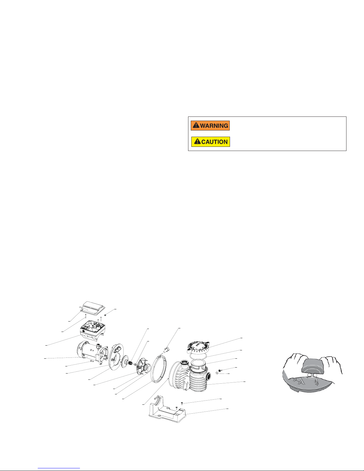
22
Pump Reassembly/Installing New Seal
1. Clean the ceramic seat of dirt, grease, dust, etc.
Wet the outer edge of the rubber cup on the ceramic
seat with water. Press the ceramic seal into the seal
plate firmly and squarely with finger pressure. See
seal image below.
2. Place ceramic seat face up on bench and reclean
the cavity if seat does not lock properly.
3. If the seat still does not lock properly, place a
cardboard washer over the polished face and use
a piece of 3/4” standard pipe for pressing purposes.
4. Remount seal plate on the motor. Tighten the bolts
to 60-80 inch-lbs. (69-92kg/cm) torque.
5. Apply a small amount of liquid detergent to the
inside diameter of rotating half of seal.
6. Slide the rotating seal member, polished face last,
over impeller sleeve until the rubber drive ring
contacts the shoulder.
Note: Be sure not to nick or scratch the polished
seal face. The seal will leak if the face is damaged.
7. Screw the impeller onto the shaft (clockwise); this
will automatically lock the seal in the seal plate.
Note: On models with an impeller screw: Install the
impeller gasket and lock screw (left-hand thread turn counter-clockwise). Torque lock screw to 50-55
inch-lbs. (57.6-63 kg/cm).
8. Mount the diffuser on the seal plate. Tighten screws
to 10-14 inch-lbs. (11.2-16.1 kg/cm) torque.
9. Assemble the motor and seal plate to the volute.
Be sure the clamp is properly seated.
Note: Clamp knob can be located in any position
around volute; if it is moved after assembly, tighten
knob while tapping around clamp to assist sealing.
Do not move clamp while pump is full of water.
10. Reconnect the RS-485 communication cable to the pump.
11. Fill the pump with water.
12. Reinstall the pump lid and plastic clamp. See “Pump
Strainer Basket” on page 20 for details.
13. Turn on the pump circuit breakers at the main panel.
14. Prime the pump. See “Priming the Pump,” on page 4 for
more information.
Drive Assembly Removal and Installation
To avoid dangerous or fatal electrical shock hazard, switch
OFF power to motor before working on pump or motor.
To avoid electrical hazard, do not remove the four tamper
proof screws from the motor assembly.
To remove the drive and control panel from the motor
assembly:
1. Be sure all electrical breakers and switches are turned off
before removing the control panel.
2. Disconnect the RS-485 communication cable from the
pump.
3. Remove the four (4) Phillips head screws from the outer
corners of the keypad.
4. Unplug the keypad from the drive and set it to the side in
a safe place.
5. Remove the three (3) Phillips head screws, located inside
the drive, that anchor the drive to the motor.
6. Lift up the drive assembly and remove it from the motor
adapter located on top of the motor assembly.
Note: Be careful not to remove the gasket between the
drive and motor, it is critical in keeping moisture out of the
drive and motor. Replace the gasket if damaged. Do not
reassemble with a damaged or missing gasket.
KEYPAD COVER
KEYPAD TO
DRIVE SCREWS
CAPTIVE (4X)
DRIVE TO MOTOR
SCREWS (3X)
DRIVE
MOTOR
MOTOR TO SEALPLATE
BOLT (4X)
SEAL PLATE
IMPELLER
DIFFUSER
DIFFUSER SCREWS (5X)
DIFFUSER O-RING
HEYCO PLUG FOR
KEYPAD RELOCATION CABLE
BAND CLAMP
SEAL PLATE O-RING
Pump Illustrated Parts View
INTELLIPRO® 2 VST Variable Speed Pump Installation and User’s Guide
MECHANICAL
SEAL
IMPELLER
SCREW
BAND CLAMP
KNOB
LOCKING RING/LID
LID O-RING
STRAINER BASKET
DRAIN PLUG (2X)
DRAIN PLUG O-RING (2X)
VOLUTE
SCREW, VOLUTE TO BASE
PUMP BASE/
MOTOR SUPPORT
Press Seal into plate firmly
Page 27
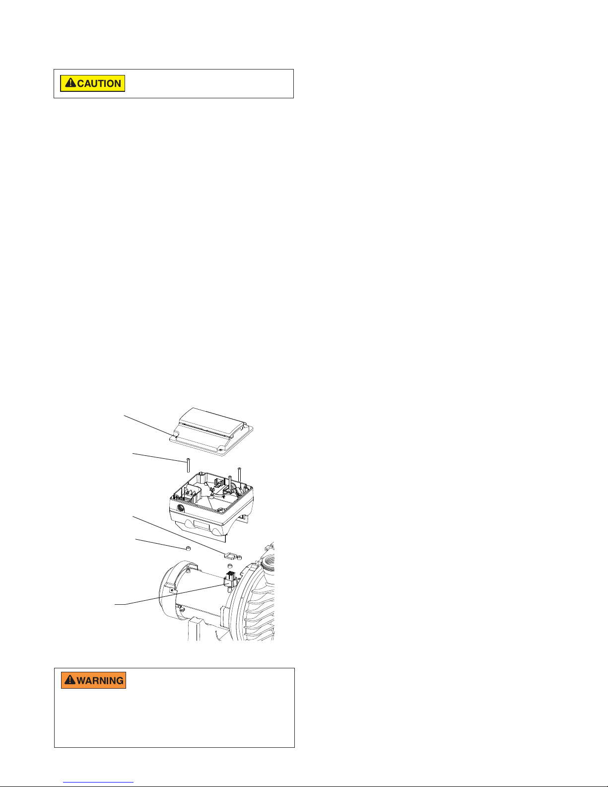
23
Drive Assembly Removal and
Installation,
To install the drive assembly onto the motor
assembly:
1. Be sure all electrical breakers and switches are
turned off before installing the drive.
2. Be sure that the drive gasket is installed onto the
adapter connector. It is critical in keeping moisture
out of the drive and motor. Replace the gasket if
damaged. Do not reassemble with a damaged or
missing gasket.
3. Verify that the three (3) orange motor post caps are
in position before placing the drive on the motor
assembly.
4. Align the drive assembly with the motor adapter and
seat the drive on the motor assembly.
5. Secure and tighten the drive assembly with the three
(3) Phillips head screws.
6. Plug the keypad back into the drive.
7. Place the keypad in the desired orientation on the
drive and reattach the four (4) screws in the corners
of the drive.
Note: Ensure that the keypad cable is not being
pinched between the drive and keypad.
Keypad Screws
(4x)
Drive to Motor
Screws (3x)
Drive Gasket
Orange Motor
Post Caps (3x)
Adapter
Connector
risk of fire, do not allow leaves, debris, or foreign matter to collect
around the pump motor. To avoid burns when handling the motor, shut
off the motor and allow it to cool for 20 minutes before servicing. The
pump provides an automatic internal cutoff switch to protect the motor
from heat damage during operation.
(continued)
Before installing this product, read and follow all
warning notices and instructions on page ii - iii.
Drive Assembly and Removal
FIRE and BURN HAZARD - The pump motor
may run at a high temperatures. To reduce the
Alerts and Warnings
The IntelliPro® 2 VST Variable Speed Pump displays all
alarms and warnings on the control panel display. When
an alarm or warning condition exists, the corresponding
light will be lit on the display.
All control panel buttons are disabled until the alarm
or warning is acknowledged with the Reset button.
Pressing the Reset button will clear the alarm once the
fault condition has been resolved.
Note: The pump will not start if the impeller is rotating.
Power Out/OFF
The incoming supply voltage is less than required.
The drive faults to protect itself from over current. The
drive contains capacitors that keep it powered up long
enough to save the current run parameters. If power is
restored during this process, approximately 20
seconds, the drive will not restart until completed.
Priming Failure
If the pump is not defined as primed within the “Max
Priming Time” it will stop and generate a “Priming
Alarm” for 10 minutes, then attempt to prime again. The
“Max Priming Time” is set by the user on the priming
menu as discussed on page 13. If the pump cannot
prime within five attempts it will generate a permanent
alarm that must be manually reset.
Overheat
If the drive temperature gets above 54.4° C (130° F) the
pump will slowly reduce speed until the over
temperature condition clears.
Thermal Mode
When active, the motor will run at the preset RPM
until the drive internal temperature increases above
the minimum. The pump’s internal thermal protection
is disabled when connected to an automation system.
Thermal protection is provided by selecting YES at the
ON WITH FREEZE portion of the circuit function menu
in the IntelliTouch
internal thermal protection, the power to the drive must
be cycled off then back on. Important: See explanation
of Thermal Mode on page 16.
Over Current
Indicated that the drive is overloaded or the motor has
an electrical problem. The drive will restart 20 seconds
after the over current condition clears.
Over Voltage
Indicates excessive supply voltage or an external water
source is causing the pump and motor to rotate thereby
generating an excessive voltage on the drives internal
DC buss. The drive will restart 20 seconds after the over
voltage condition clears.
Internal Error
Indicates that the self-monitoring motor control software
has encountered an error. Clear the alarm and restart
the pump. If this alarm persists, contact Pentair Technical
Service at 1-800-831-7133.
®
Control System. To re-enable the
INTELLIPRO® 2 VST Variable Speed Pump Installation and User’s Guide
Page 28

24
TROUBLESHOOTING
Always disconnect power to the IntelliPro® 2 VST Variable Speed Pump at the circuit breaker and disconnect the communication
cable before servicing the pump. Failure to do so could result in death or serious injury to serviceman, pool users or others due to
electric shock. DO NOT attempt to adjust or service without consulting your dealer or a qualified pool technician. Read the entire
Installation & User’s Guide before attempting to use, service, or adjust the pool filtering system or heater.
Problem Possible Cause Corrective Action
Pump failure.
(For alert display
messages, refer to Alerts
and Warnings on page 23).
Reduced capacity and/
or head.
(For alert display
messages, refer to Alerts
and Warnings on page 23).
Inadequate circulation.
(For alert display
messages, refer to Alerts
and Warning on page 23).
Pump will not prime - Air leak in suction.
PRIME ERROR may be displayed.
Pump will not prime - Not enough water.
Pump does not come out of priming mode.
Pump completes priming mode too early, and/or
there is still a large amount of air in the housing
Pump stainer basket is clogged.
Pump strainer gasket is defective.
Air pockets or leaks in suction line.
PRIMING FAILURE may be displayed.
Clogged impeller.
PRIMING FAILURE may be displayed.
Pump strainer pot clogged.
PRIMING FAILURE may be displayed.
Filter or pump basket dirty.
Suction/discharge piping is too small.
Speed is set too slow for proper filtration cycle.
Check suction piping and valve glands on any
suction gate valves. Secure lid on pump strainer pot
and be sure lid gasket is in place. Check water level
to be sure skimmer is not drawing air.
Be sure the suction lines, pump, strainer, and pump
volute are full of water.
Adjust priming range to a higher setting
(default setting is 5).
Adjust priming range to a lower setting
(default setting is 5).
Clean pump strainer pot.
Replace gasket.
Check suction piping and valve glands on any
suction gate valves.
Turn off electrical power to the pump.
Remove the (6) bolts that holds the housing (strainer
pot/volute) to seal plate. Slide the motor and seal
plate away from the volute.
Clean debris from impeller. If debris cannot be
removed, complete the following steps:
1. Remove diffuser and o-ring.
2. Remove reverse-thread impeller screw and o-ring.
3. Remove, clean and reinstall impeller.
4. Reinstall reverse-thread impeller screw and o-ring.
Reinstall diffuser, and o-ring.
Reinstall motor and seal plate into volute.
Reinstall seal plate nuts and volute and tighten
securely.
Clean suction trap.
Clean pump strainer pot.
Check trap basket; if plugged, turn pump off and
clean basket.
Check and clean pool filter.
Increase piping size.
Increase filtration run time.
INTELLIPRO® 2 VST Variable Speed Pump Installation and User’s Guide
Page 29

Troubleshooting, Continued
Problem Possible Cause Corrective Action
25
Electrical problem.
alert display
(For
messages, refer to Alerts
and Warning on page 23).
Control panel LCD screen
displays sporadically or
flickers on/off.
Mechanical troubles and
noise.
Pump does not respond
to IntelliTouch,
EasyTouch,
SunTouch, IntelliComm
system commands.
Could appear as a “Low Voltage” alarm.
Check voltage at motor terminals and at panel while
pump is running. If low, see wiring instructions or
consult power company.
Check for loose connections.
Could appear as “Over Heat” alert.
Check line voltage; if less than 90% or more than
110% of rated voltage consult a licensed electrician.
Increase ventilation.
Reduce ambient temperature.
Tighten any loose wiring connections.
Motor runs too hot. Turn power to motor off.
Check for proper voltage.
Check for proper impeller or impeller rubbing.
Loose drive wiring connection. Check the connection between the drive and keypad.
See image on page 3. The drive wiring connection
should be tight.
The pump motor is running but with loud noise.
If suction and discharge piping are not adequately
supported, pump assembly will be strained. Do not
mount pump on a wooden platform! Securely mount
on concrete platform for quietest performance.
Foreign matter (gravel, metal, etc.) in
pump impeller.
Cavitation.
Disassemble pump, clean impeller, follow pump service instructions for reassembly.
Improve suction conditions.
Increase pipe size.
Decrease number of fittings.
Increase discharge pressure.
Speaking noise, especially evident at pump startup or slow down.
Inspect motor slinger and motor shaft seal behind
the slinger (NOT the pump’s mechanical seal). Apply
lubrication to the motor shaft rubber seals.
Improper automation setup.
1. Be sure that the communication cable is
connected at both ends.
2. Check that the pump local address matches with
the address used in the IntelliTouch control system.
3. Check that the pump has been assigned a circuit
name on the IntelliTouch control system.
4. Ensure that the pump display says
“DISPLAY NOT ACTIVE”.
Communication network inoperative.
A defective device on the network can inhibit the
proper operation of other network device. Devices
should be disconnected sequentially until the
network starts working.
INTELLIPRO® 2 VST Variable Speed Pump Installation and User’s Guide
Page 30
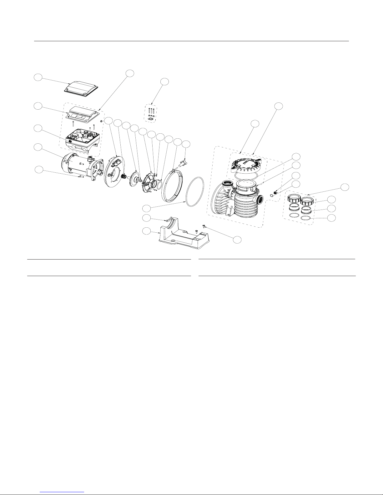
26
REPLACEMENT PARTS
IntelliPro® 2 VST Variable Speed Pump Replacement Parts (Black Colored Pumps)
6
7
11
8
9
10
1
2
3
12
13
14
15
16
17
18
19
20
31
29
30
4
21
22
23
24
28
5
25
26
27
Item Part
No. No. Description
1 356893Z DRIVE KIT W/ KEYPAD (Includes Item #2, 7
and 8)
2 355685 DRIVE HARDWARE KIT (Includes Drive
Screws, Drive Gasket and Screw Caps)
3 17307-0110S TANK BODY ASSEMBLY (Includes Trap Cover
and Item #21-24)
4 17307-0111S
and Item #21)
5 42001-0402 2” SLIP UNION HALF KIT (Includes Item #25-27)
6 356905Z KEYPAD RELOCATION KIT (Includes Keypad
Relocation Cable and Blank Drive Cover)
7 358527Z KEYPAD ASSEMBLY KIT
8 356892Z DRIVE KIT
9 350306S MOTOR 3.2KW FERRITE BLK
10 U30-74SS 3/8-16 X 1” HEX HEAD SS (Qty. 4)
11 C103-194P SEAL PLATE
12 17351-0101S SHAFT SEAL, EPDM BLACK
13 C105-238PLA IMPELLER ASSEMBLY
14 37007-6080 IMPELLER SCREW
15 C1-271P DIFFUSER
16 U43-21SS #8 EXT TOOTH WASHER (Qty. 5)
TRAP COVER ASSEMBLY (Includes Trap Cover
Item Part
No. No. Description
17 U30-922SS DIFFUSER SCREW
18 U9-374 DIFFUSER O-RING
19 C19-37a V-CLAMP
20 WC-36-22 CLAMP, KNOB
21 35505-1440 TRAP O-RING, 6.90 O.D. 6.35 I.D.
22 C8-58P TRAP BASKET
23 U78-920P DRAIN PLUG (Qty. 2)
24 U9-359 DRAIN PLUG O-RING (Qty. 2)
25 U11-200PS UNION COLLAR (Qty. 2)
26 U11-196PS 2” SLIP ADAPTER (Qty. 2)
27 U9-362 O-RING, #2-231 (Qty. 2)
28 U30-918 BASE SCREW, 5/16-14 X 1 IN LG HI-LO HEX
(Qty. 2)
29 C35-11 MOTOR PAD
30 C4-78P MOTOR BASE
31 U9-228A TRAP COVER ASSEMBLY O-RING
* 350122 50 FT. COMMUNICATION CABLE
* 354045 POWER END INTELLIPRO 2 VST
Note: (*) Items not shown
INTELLIPRO® 2 VST Variable Speed Pump Installation and User’s Guide
Page 31

27
Pump Dimensions
362
14.2
371
14.6
114
4.5
664
26.1
291
11.4
95
3.7
274
10.8
435
17.1
249
9.8
177
7.0
Electrical Specifications
Circuit Protection: Two-pole 20 AMP device at the Electrical Panel.
Input: 208-230 VAC, 50/60 Hz, 3200 Watts Maximum, 1 phase
Pump Performance Curves
100
MAX SP EED - 3450 RPM
90
80
70
60
50
40
30
SPEED 4 - 3110 RPM
SPEED 3 - 2350 RPM
SPEED 2 - 1500 RPM
20
TOTAL DYNAMIC HEAD IN FT OF WATER
10
SPEED 1 - 750 RPM
0
0 102030405060708090100110120130140150160170180
FLOW RATE IN US GALLONS PER MINUTE
INTELLIPRO® 2 VST Variable Speed Pump Installation and User’s Guide
Page 32

28
Operator Control Panel: Pump Menu Quick Reference Guide
MENU
SETTINGS
(pages 8-10)
SPEED 1-8
(pages 10-12)
Press MENU button to access menus
Set Date and Time
Set Speed Max/Min
Device
Alarm Log (1-10)
Speed 1-4
Speed 5-8
Date
Time
Hour Format
Min Speed (450-1700 RPM) - Default: 450 RPM
Max Speed (1900-3450 RPM) - Default: 3450 RPM
Pump Address (1-16) - Default: 1
Screen Contrast (1-5) - Default: 3
Language
Temperature Unit Fahrenheit - Default F°
Password
Firmware Version
Manual
Schedule
Egg Timer
Disabled
Schedule
Months (1-12)
Days (1-31)
Years (2000-2050 Plus)
Hours (24hr Mode: 0-23) (12hr Mode: 1-12 AM & PM)
Minutes (0-60)
AM/PM - Default: AM/PM
24 Hour
English - Default: English
Português
Deutsch
Italiano
Nederlands
Español
Français
Celsius C°
Disabled - Default: Disabled
Enabled
Set Speed - Default Spd 1-2: Manual
Set Speed
Set Start Time
Set Stop Time
Set Speed - Default Spd 3-4: Egg Timer
Time
Default: Disabled
Set Speed
Set Start Time
Set Stop Time
Password Timeout (1 min. to 6 hrs.) - Default: 1 minute
Set Password (0000 - 9999) - Default: 1234
EXT CONTROL
(page 12)
FEATURES
(page 13)
PRIMING
(pages 13-15)
THERMAL MODE
(page 16)
Program 1
Program 2
Program 3
Program 4
Time Out
Quick Clean
Disabled/Enabled
Priming Speed
Max Priming Time
Priming Range
Priming Delay
Disabled/Enabled
Set Speed
Pump Temperature
Set Speed (450-3450 RPM) - Default: 750 RPM
Stop Delay (0 min. to 10 min.) Default: 0 minutes
Set Speed (450-3450 RPM) - Default: 1500 RPM
Stop Delay (0 min. to 10 min.) Default: 0 minutes
Set Speed (450-3450 RPM) - Default: 2350 RPM
Stop Delay (0 min. to 10 min.) Default: 0 minutes
Set Speed (450-3450 RPM) - Default: 3110 RPM
Stop Delay (0 min. to 10 min.) Default: 0 minutes
Time Out Duration (1 min. to 10 hrs.) Default: 3 hours
Set Speed (450-3450 RPM) Default: 3450 RPM
Quick Clean Duration (1 min. to 10 hrs.) Default: 10 minutes
Disabled / Enabled - Default: Enabled
Set Speed (2400-3450 RPM) - Default: 3450 RPM
(1 min. to 30 min.) Default: 11 minutes
(1 - 10) Default: 5
(1 sec. to 10 min.) Default: 20 seconds
Disabled / Enabled - Default: Enabled
Set Speed (450 RPM - 3450 RPM) Default 1000 RPM
40° F - 50° F (4.4° C through 10° C) Default: 40° F (4.4° C)
INTELLIPRO® 2 VST Variable Speed Pump Installation and User’s Guide
Page 33

NOTES
Page 34

NOTES
Page 35

NOTES
Page 36

*356889*
LIT. PKG. P/N 356889
1620 HAWKINS AVE., SANFORD, NC 27330 • (919) 566-8000
10951 WEST LOS ANGELES AVE., MOORPARK, CA 93021 • (805) 553-5000
WWW.PENTAIRPOOL.COM
All Pentair trademarks and logos are owned by Pentair, Inc or one of its global affiliates. Pentair Aquatic Systems®, Sta-Rite®, IntelliPro®, IntelliComm®,
EasyTouch
affiliated companies in the United States and/ or other countries. Unless expressly noted, names and brands of third parties that may be used in this
document are not used to indicate an affiliation or endorsement between the owners of these names and brands and Pentair Water Pool and Spa,
Inc. Those names and brands may be the trademarks or registered trademarks of those third parties. Because we are continuously improving our
products and services, Pentair reserves the right to change specifications without prior notice. Pentair is an equal opportunity employer.
© 2016 Pentair Water Pool and Spa, Inc. All rights reserved. This document is subject to change without notice.
®
, IntelliTouch®, SunTouch® and Eco Select® are trademarks and/or registered trademarks of Pentair Water Pool and Spa, Inc. and/or its
*356890*
P/N 356890 REV. C 6/16/16
 Loading...