

Standard horizon HX400 Owner Manual
HX400
VHF FM Marine Transceiver
Owner’s Manual
Page 1HX400

TABLE OF CONTENTS
Quick Reference Guide ............................................................................................................... 3
WARNING! FCC RF EXPOSURE REQUIREMENTS ................................................................... 4
1. GENERAL INFORMATION .................................................................................................... 6
1.1 INTRODUCTION ......................................................................................................... 6
1.2 RF EXPOSURE SAFETY STATEMENT ................................................................... 6
2. ACCESSORIES ...................................................................................................................... 7
2.1 PACKING LIST ........................................................................................................... 7
2.2 OPTIONS ..................................................................................................................... 7
3. ABOUT THIS RADIO ............................................................................................................8
3.1 ABOUT THE VHF MARINE BAND ..........................................................................8
3.2 ABOUT THE LMR CHANNELS ................................................................................ 8
3.3 ABOUT WATER RESISTANCE ................................................................................. 8
3.4 EMERGENCY (CHANNEL 16 USE).......................................................................... 8
3.5 CALLING ANOTHER VESSEL (CHANNEL 16 OR 9)............................................ 9
3.6 OPERATING ON CHANNEL 13 ............................................................................. 10
3.7 OPERATING ON CHANNEL 67 ............................................................................. 10
3.8 SIMPLEX/DUPLEX CHANNEL USE ....................................................................... 10
4. GETTING STARTED ............................................................................................................ 12
4.1 RADIO CARE ............................................................................................................ 12
4.2 BELT CLIP INSTALLATION AND REMOVAL ............................................................ 12
4.3 BATTERIES AND CHARGERS ............................................................................... 13
4.3.1 BATTERY SAFETY ....................................................................................... 13
4.3.2 BATTERY INSTALLATION AND REMOVAL................................................. 14
5. CONTROLS AND INDICATORS ......................................................................................... 16
6. BASIC OPERATION ............................................................................................................ 20
7. MENU (“SET”) MODE .......................................................................................................... 28
8. MAINTENANCE .................................................................................................................... 32
9. VHF MARINE CHANNEL ASSIGNMENT.......................................................................... 34
10. WARRANTY .......................................................................................................................... 38
11. INSTALLATION OF OPTION .............................................................................................. 41
12. SPECIFICATIONS................................................................................................................. 42
FCC AND CANADA RADIO LICENSE INFORMATION ......................................................... 44
4.3.3 BATTERY CHARGING ................................................................................. 15
5.1 CONTROLS AND SWITCHES ................................................................................ 16
5.2 LCD INDICATORS .................................................................................................... 19
6.1 INITIAL SETUP .........................................................................................................20
6.2 RECEPTION ..............................................................................................................20
6.3 TRANSMISSION ....................................................................................................... 20
6.3.1 TRANSMIT TIME-OUT TIMER (TOT)........................................................... 21
6.4 INTERNATIONAL, CANADIAN AND USA CHANNELS ........................................21
6.5 NOAA WEATHER CHANNELS ................................................................................. 22
6.5.1 NOAA WEATHER ALERT ............................................................................. 22
6.5.2 NOAA WEATHER ALERT TESTING ............................................................ 22
6.6 KEYPAD LOCKING .................................................................................................. 23
6.7 PRESET CHANNELS (0 ~ 9): INSTANT ACCESS ................................................ 23
6.7.1 PROGRAMMING .......................................................................................... 23
6.7.2 OPERATION .................................................................................................23
6.8 MEMORY SCAN ....................................................................................................... 24
6.9 PRIORITY SCAN ...................................................................................................... 25
6.10 DUAL WATCH ........................................................................................................... 26
6.11 TRI-WATCH ............................................................................................................... 26
6.12 VOICE SCRAMBLER ................................................................................................27
8.1 GENERAL .................................................................................................................. 32
8.2 REPLACEMENT PARTS .......................................................................................... 32
8.3 FACTORY SERVICE ................................................................................................. 33
8.4 TROUBLESHOOTING CHART ................................................................................ 33
11.1 FBA-42 ALKALINE BATTERY TRAY ......................................................................41
12.1 GENERAL.................................................................................................................. 42
12.2 TRANSMITTER ......................................................................................................... 42
12.3 RECEIVER ................................................................................................................ 43
HX400Page 2
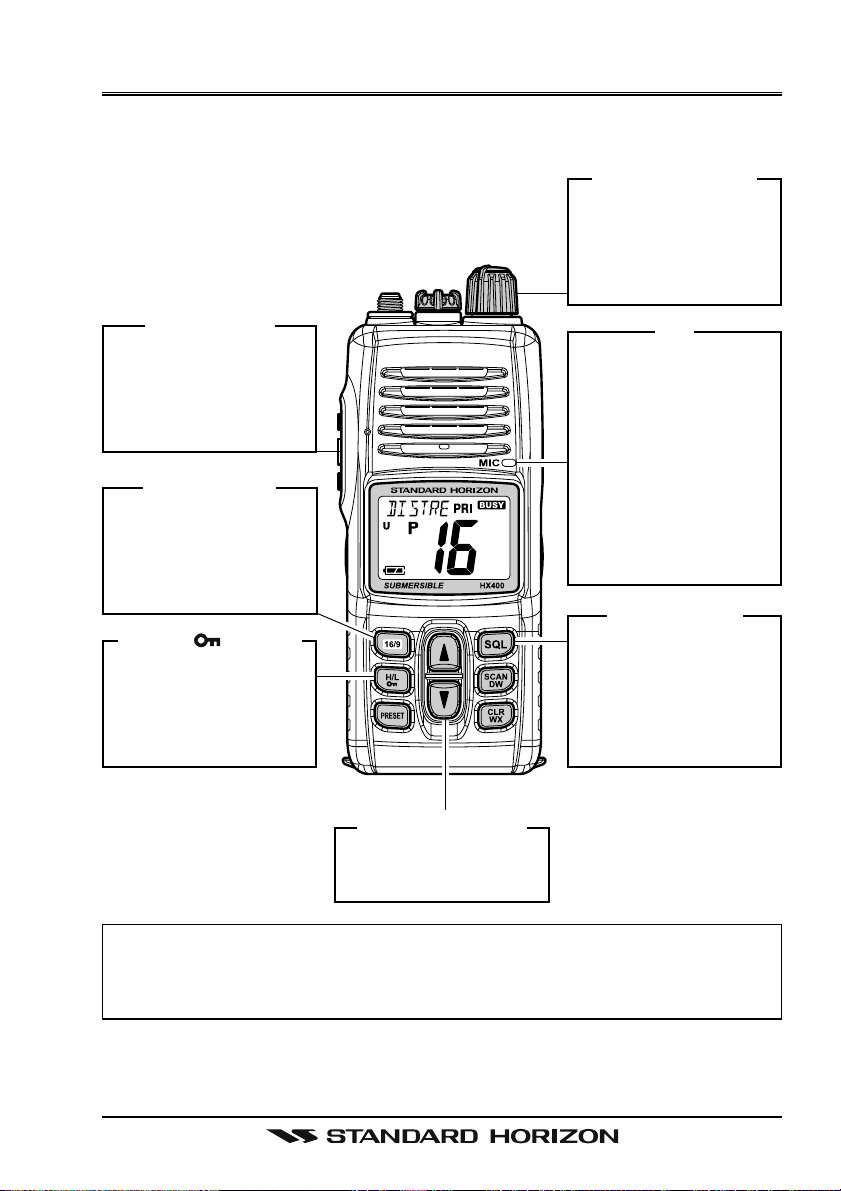
QUICK REFERENCE GUIDE
This transceiver is equipped with the E2O (Easy-To-Operate) system. You can
do the basic operation in numerical order of the illustration below.
[
[
PTT] S
16/9] B
( )]
WITCH
UTTON
B
UTTON
Speak into the microphone in a normal
voice level while
pressing this switch.
[
Press to recall
channel 16.
Press and hold to
recall channel 9.
[
H/L
Press to toggle the
transmit power between High (5W) and
Low (1W).
PWR/VOL] K
Rotate this knob
clockwise to turn on
the radio, and adjust
the audio level.
MIC
When transmitting,
position your mouth
about 1/2 ~ 1 inch
(1.2 ~ 2.5 cm) away
from the small mic
hole.
Speak slowly and
clearly into the microphone.
[
SQL] B
Press this key first,
then press the [
key to squelch or
press the [] key to
un-squelch the radio.
NOB
UTTON
]
[]/[]
Selects the operating
channel.
For additional details, refer to next page or section “5. CONTROLS AND
INDICATORS”.
NOTE
B
UTTONS
Page 3HX400
WARNING! FCC RF EXPOSURE REQUIREMENTS
This Radio has been tested and complies with the Federal Communications
Commission (FCC) RF exposure limits for Occupational Use/Controlled exposure environment. In addition, it complies with the following Standards and
Guidelines:
FCC 96-326, Guidelines for Evaluating the Environmental Effects of Ra-
dio-Frequency Radiation.
FCC OET Bulletin 65 Edition 97-01 (2001) Supplement C, Evaluating Com-
pliance with FCC Guidelines for Human Exposure to Radio Frequency
Electromagnetic Fields.
ANSI/IEEE C95.1-1992, IEEE Standard for Safety Levels with Respect to
Human Exposure to Radio Frequency Electromagnetic Fields, 3 kHz to
300 GHz.
ANSI/IEEE C95.3-1992, IEEE Recommended Practice for the Measure-
ment of Potentially Hazardous Electromagnetic Fields - RF and Microwave.
WARNING:
This radio generates RF electromagnetic energy during transmit mode. This
radio is designed for and classified as Occupational Use Only, meaning it
must be used only during the course of employment by individuals aware of
the hazards, and the ways to minimize such hazards. This radio is not intended for use by the General Population in an uncontrolled environment.
CAUTION:
To ensure that your expose to RF electromagnetic energy is within the FCC
allowable limits for occupational use, always adhere to the following guidelines:
This radio is NOT approved for use by the general population in an uncon-
trolled exposure environment. This radio is restricted to occupational use,
work related operations only where the radio operator must have the knowledge to control his or her RF exposure conditions.
When transmitting, hold the radio in a vertical position with its microphone
2 inches (5 cm) away from your mouth and keep the antenna at least 2
inches (5 cm) away from your head and body.
The radio must be used with a maximum operating duty cycle not exceed-
ing 50%, in typical Push-to-Talk configurations.
DO NOT transmit for more than 50% of total radio use time (50% duty
cycle). Transmitting more than 50% of the time can cause FCC RF exposure compliance requirements to be exceeded.
HX400Page 4

SAR compliance for body-worn use was only demonstrated for the spe-
cific belt-clip. Other body-worn accessories or configurations may NOT
comply with the FCC RF exposure requirements and should be avoided.
DO NOT transmit when the radio is used in Body Worn configuration with
the following accessory: belt-clip.
It must be used ONLY for (1) there is 4 cm distance from the body during
transmitting, (2) monitoring purposes, using the speaker only and (3) for
carrying purposes.
Always use Standard Horizon authorized accessories.
The information listed above provides the user with the information needed
to make him or her aware of RF exposure, and what to do to assure that
this radio operates with the FCC RF exposure limits of this radio.
Electromagnetic Interference/Compatibility
During transmissions, this radio generates RF energy that can possibly
cause interference with other devices or systems. To avoid such interference, turn off the radio in areas where signs are posted to do so.
Do not operate the transmitter in areas that are sensitive to electromagnetic radiation such as hospitals, health care facilities, aircraft, and blasting sites.
Page 5HX400

1. GENERAL INFORMATION
1.1 INTRODUCTION
Congratulations on your purchase of the HX400! Whether this is your first
portable marine VHF transceiver, or if you have other STANDARD HORIZON
equipment, the STANDARD HORIZON organization is committed to ensuring
your enjoyment of this high performance transceiver, which should provide
you with many years of satisfying communications even in the harshest of
environments. STANDARD HORIZON technical support personnel stands
behind every product sold, and we invite you to contact us should you require
technical advice or assistance.
The HX400 is a JIS-8 / IPX8 (1.5 m (about 5Ft) for 30 minutes) Submersible 5Watt portable two way marine transceiver with the capability to be programmed
with 40 LMR (Land Mobile Radio) channels with CTCSS or DCS signalling by
a dealer. The transceiver has all allocated USA, Canadian, or International
channels. It has emergency channel 16 which can be immediately selected
from any channel by pressing the key.
The HX400 includes the following features: 10 programmable Preset Channels, Memory, Priority, Dual Watch and TRI-Watch scanning, Battery Saver,
easy-to-read large LCD display, EEPROM memory back-up, Battery Life displayed on the LCD, and a transmit Time-Out Timer (TOT), Noise Canceling
Microphone and Voice Scrambler.
The HX400 transmitter provides a full 5 Watt of transmit power and also is
selectable to 1 Watt to assist the user in ensuring maximum battery life.
We appreciate your purchase of the HX400, and encourage you to read this
manual thoroughly, so as to learn and fully understand the capabilities of the
HX400.
1.2 RF EXPOSURE SAFETY STATEMENT
Your wireless handheld portable transceiver contains a low power transmitter.
When the Push-To-Talk (PTT: ) button is pushed, the transceiver sends out
radio frequency (RF) signals.
This device is authorized to operate at a duty factor not to exceed 50% (this
corresponds to 50% transmission time and 50% reception time).
This transmitter and its antenna must maintain a separation distance of at
least 1 inch (2.5 cm) from your face. Speak in a normal voice, with the antenna
pointed up and away from the face at the required separation distance.
Use only the supplied antenna. Unauthorized antennas, modifications, or attachments could damage the transmitter.
HX400Page 6
2. ACCESSORIES
2.1 PACKING LIST
When the package containing the transceiver is first opened, please check it
for the following contents:
HX400 Transceiver
CAT460 Antenna
FNB-115LI 7.4 V, 2400 mAh Li-Ion Battery Pack
CD-50 Charger Cradle for HX400
PA-45B 120VAC Wall Charger for CD-50
E-DC-30 DC Cable with 12 V Cigarette Lighter Plug
CLIP-22 Belt Clip
Hand Strap
Owner’s Manual
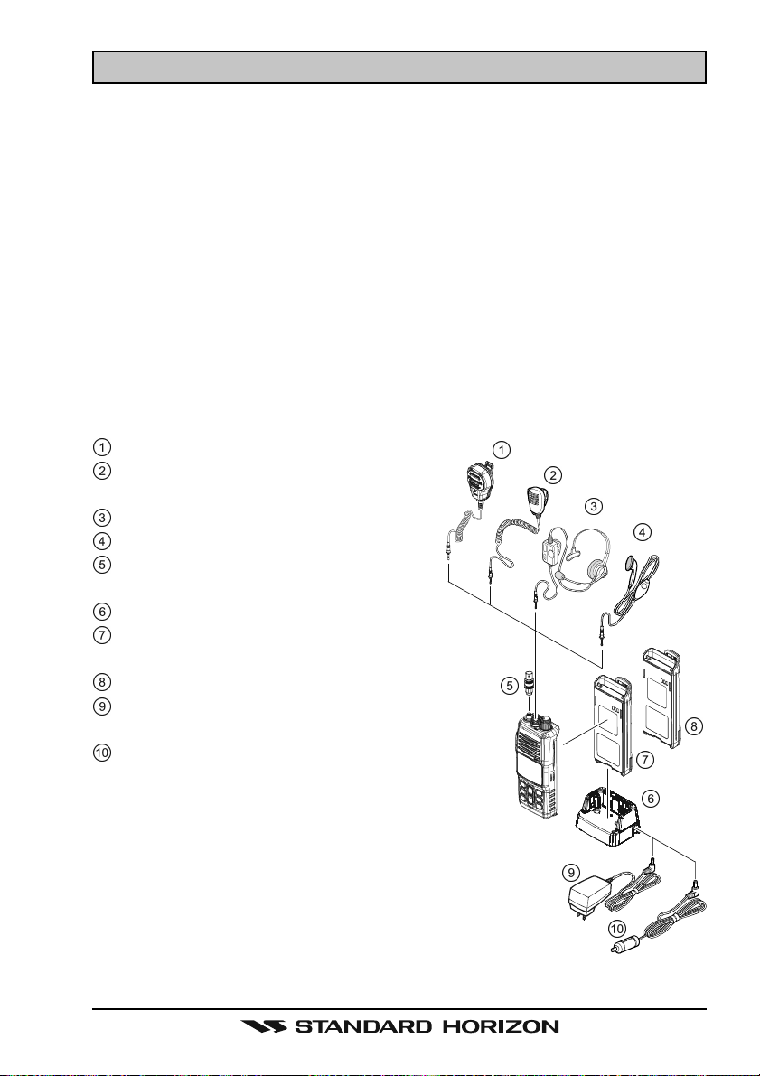
2.2 OPTIONS
MH-73A4B Speaker/Microphone
MH-57A4B Mini Speaker/Micro-
phone
VC-24 VOX Headset
VC-27 Earpiece/Microphone
CN-3 Radio-to-Ship’s Antenna
Adapter
CD-50 Charger Cradle
FNB-115LI 7.4 V, 2400 mAh Li-Ion
Battery Pack
FBA-42 Alkaline Battery Case
PA-45B/C/UAC Wall Charger for the
FNB-115LI
E-DC-30 DC Cable with 12 V Ciga-
rette Lighter Plug
: “B” suffix is for use with 120 VAC (Type-A
plug), “C” suffix is for use with 230 VAC
(Type-C plug), and “U” suffix is for use
with 230 VAC (Type-BF plug).
Note: Before operating the HX400 for the
first time, it is recommended that the battery
be charged. Please see section “4.3.3 BAT-
TERY CHARGING” for details.
Page 7HX400

3. ABOUT THIS RADIO
3.1 ABOUT THE VHF MARINE BAND
The radio frequencies used in the VHF marine band lie between 156 and 162
MHz. The marine VHF band provides communications over distances that are
essentially “Line of sight” Actual transmission range depends much more on
antenna type, gain and height than on the power output of the transmitter. On
a fixed mount 25 W radio transmission expected distances can be greater
than 15 miles, for a portable 5 W radio transmission the expected distance can
be greater than 5 miles in “Line of sight”.
The user of a Marine VHF radio is subject to severe fines if the radio is used on
land. The reasoning for this is you may be near an inland waterway, or propagation anomalies may cause your transmission to be heard in a waterway. If
this occurs, depending upon the marine VHF channel on which you are transmitting, you could interfere with a search and rescue case, or contribute to a
collision between passing ships. For VHF Marine channel assignments refer
to page 34 section 9.
3.2 ABOUT THE LMR CHANNELS
The HX400 is capable of being programmed with 40 LMR (Land Mobile Radio)
channels by a dealer. The frequency range is 134 to 174MHz which may be
setup for 25 kHz (wide) or 12.5 kHz (narrow) channel stepping with CTCSS
and DCS signaling. Contact your dealer for further details.
3.3 ABOUT WATER RESISTANCE
Water resistance of the transceiver is ensured only when the battery pack is
attached to the transceiver and MIC/SP cap is installed in the MIC/SP jack.
3.4 EMERGENCY (CHANNEL 16 USE
Channel 16 is known as the Hail and Distress Channel. An emergency may be
defined as a threat to life or property. In such instances, be sure the transceiver is on and set to “Channel 16”. Then use the following procedure:
1. Press the PTT (Push-To-Talk: ) switch and say “Mayday, Mayday, May-
day. This is _____, _____, _____” (your vessel’s name).
2. Then repeat once: “Mayday, _____” (your vessel’s name).
3. Now report your position in latitude/longitude, or by giving a true or mag-
netic bearing (state which) to a well-known landmark such as a navigation
aid or geographic feature such as an island or harbor entry.
4. Explain the nature of your distress (sinking, collision, aground, fire, heart
attack, life-threatening injury, etc.).
5. State the kind of assistance your desire (pumps, medical aid, etc.).
)
HX400Page 8

6. Report the number of persons aboard and condition of any injured.
7. Estimate the present seaworthiness and condition of your vessel.
8. Give your vessel’s description: length, design (power or sail), color and other
distinguishing marks. The total transmission should not exceed 1 minute.
9. End the message by saying “OVER”. Release the PTT
listen.
10. If there is no answer, repeat the above procedure. If there is still no response, try another channel.
( )
switch and
3.5 CALLING ANOTHER VESSEL (CHANNEL 16 OR 9
Channel 16 may be used for initial contact (hailing) with another vessel.
However, its most important use is for emergency messages. This channel
must be monitored at all times except when actually using another channel.
It is monitored by the U.S. and Canadian Coast Guards and by other vessels.
Use of channel 16 for hailing must be limited to initial contact only. Calling
should not exceed 30 seconds, but may be repeated 3 times at 2-minute intervals. In areas of heavy radio traffic, congestion on channel 16 resulting from its
use as a hailing channel can be reduced significantly in U.S. waters by using
Channel 9 as the initial contact (hailing) channel for non-emergency communications. Also hailing on channel 9, the calling time should not exceed 30 seconds but may be repeated 3 times at 2-minute intervals.
Prior to making contact with another vessel, refer to the channel charts in this
manual, and select an appropriate channel for communications after initial
contact. For example, Channels 68 and 69 of the U.S. VHF Charts are some of
the channels available to non-commercial (recreational) boaters. Monitor your
desired channel in advance to make sure you will not be interrupting other
traffic, and then go back to either channel 16 or 9 for your initial contact.
When the hailing channel (16 or 9) is clear, state the name of the other vessel
you wish to call and then “this is” followed by the name of your vessel and
your Station License (Call Sign). When the other vessel returns your call, immediately request another channel by saying “go to”, the number of the other
channel, and “over”. Then switch to the new channel. When the new channel
is not busy, call the other vessel.
)
After a transmission, say “over”, and release the PTT (Push-To-Talk: ) switch.
When all communication with the other vessel is completed, end the last transmission by stating your Call Sign and the word “out”. Note that it is not necessary to state your Call Sign with each transmission, only at the beginning and
end of the contact.
Remember to return to Channel 16 when not using another channel.
Page 9HX400

3.6 OPERATING ON CHANNEL 13
Channel 13 is used at docks, bridges and for maneuvering in port. Messages
on this channel must concern navigation only, such as meeting and passing in
restricted waters. In emergencies and when approaching blind river bends,
High power is allowed. Pressing the key will change the power output from
Low Power (1 Watt) to High (5 Watts). When you change from this channel
then return to it, low power will be automatically selected.
3.7 OPERATING ON CHANNEL 67
When channel 67 is used for navigational bridge-to-bridge traffic between ships,
High power may be used temporarily (in the USA band) by pressing the
key. When release the PTT switch, the transceiver will revert to low power.
3.8 SIMPLEX/DUPLEX CHANNEL USE
Refer to the VHF MARINE CHANNEL CHART (page 35) for instructions on
use of simplex and duplex channels.
NOTE
All channels are factory-programmed in accordance with FCC, Industry
Canada, and International regulations. The mode of operation cannot
be altered from simplex to duplex or vice-versa. Simplex (ship to ship)
or duplex (marine operator) mode is automatically activated, depending
on the channel and whether the USA, Canadian or International operating band is selected.
HX400Page 10

MEMO
Page 11HX400
4. GETTING STARTED
4.1 RADIO CARE
CAUTION
Before following the instructions below, insure the battery pack is in place
and firmly connected. Care must be taken if the radio was dropped and
a close inspection may be needed to insure the radio case and gaskets
are in adequate condition.
The design of the HX400 allows water to enter between the radio and the
battery pack, however waterproof performance is not compromised.
After using the HX400 in salt water environment is recommended to clean the
radio with fresh water by rinsing the battery and radio (separately) under a sink
facet or by dunking in a fresh water. After washing,use a soft cloth to thoroughly dry all parts of the radio and battery.
This will keep the radio parts and the battery clean and in top operating condition.
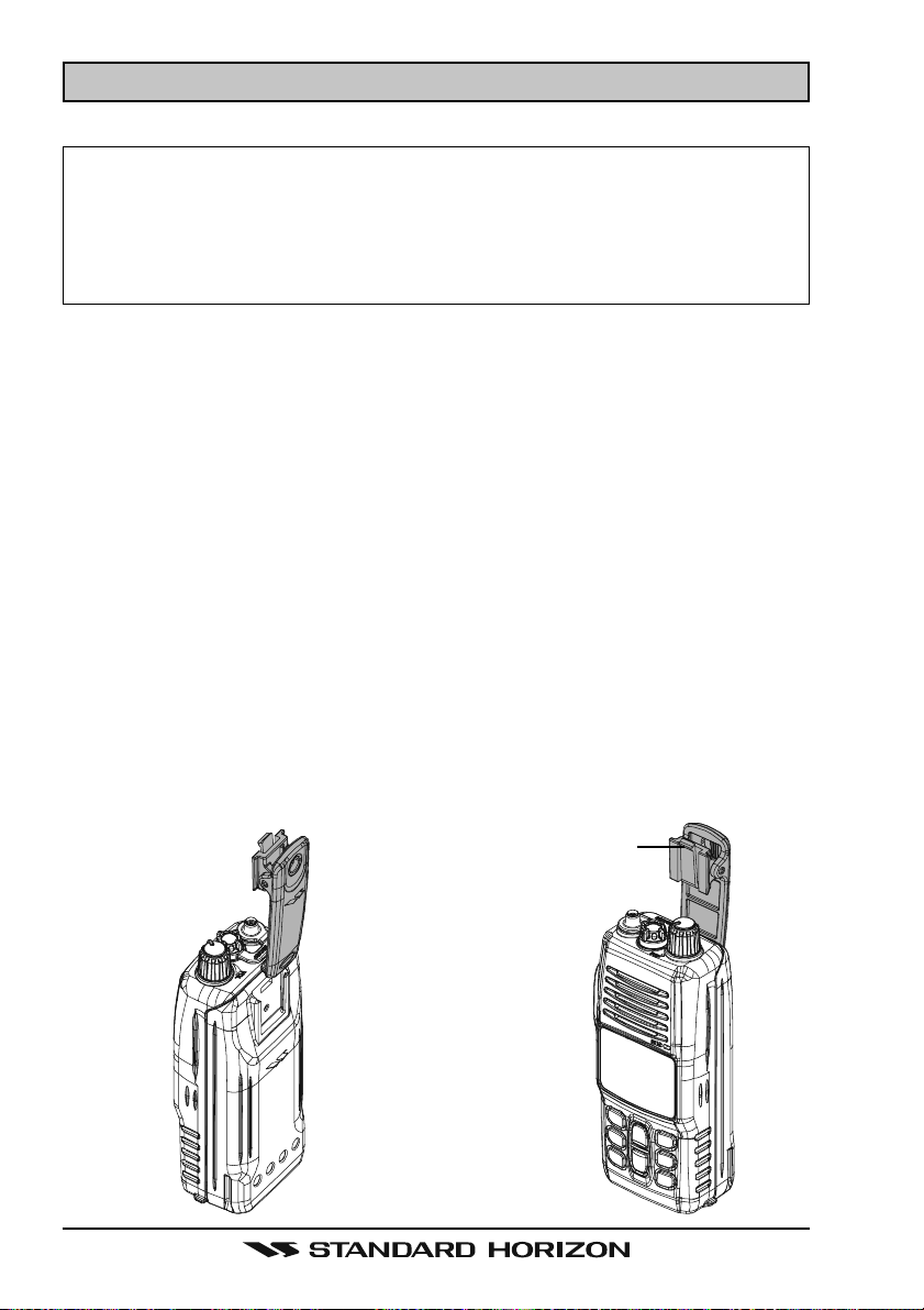
4.2 BELT CLIP INSTALLATION AND REMOVAL
To install the Belt Clip: align the
Belt Clip to the groove of the Battery pack, then press the Belt Clip
downward until it locks in place
with a “Click.”
To remove the Belt Clip: press the
Belt Clip Tab away from the battery pack to unlock the Belt Clip,
then slide the Belt Clip upward to
remove it.
Belt Clip Tab
HX400Page 12

4.3 BATTERIES AND CHARGERS
If the radio has never been used, or its charge is depleted, it may be charged by
connecting the CD-50 Charger Cradle with the PA-45B Battery Charger, as
shown in the illustration. If 12V DC power is available, the supplied E-DC-30
DC Cable with 12 V Cigarette Lighter Plug may be used for charging the battery. The PA-45B and E-DC-30 will charge a completely discharged FNB-115LI
battery pack in approximately 3 hours.
The FNB-115LI is a high performance Li-Ion battery providing high capacity in
a compact package.
CAUTION
To avoid risk of explosion and injury, FNB-115LI battery pack should
only be removed, charged or recharged in non-hazardous environments.
4.3.1 BATTERY SAFETY
Battery packs for your transceiver contain Li-Ion batteries. This type of battery
stores a charge powerful enough to be dangerous if misused or abused, especially when removed from the transceiver. Please observe the following precautions:
DO NOT SHORT BATTERY PACK TERMINALS: Shorting the terminals that
power the transceiver can cause sparks, severe overheating, burns, and battery cell damage. If the short is of sufficient duration, it is possible to melt
battery components. Do not place a loose battery pack on or near metal surfaces or objects such as paper clips, keys, tools, etc. When the battery pack is
installed on the transceiver, the terminals that transfer current to the transceiver are not exposed. The terminals that are exposed on the battery pack
when it is mounted on the transceiver are charging terminals only and do not
constitute a hazard.
DO NOT INCINERATE: Do not dispose of any battery in a fire or incinerator.
The heat of fire may cause battery cells to explode and/or release dangerous
gases.
Battery Maintenance
For safe and proper battery use, please observe the following:
Battery packs should be charged only in non-hazardous environments;
Use only STANDARD HORIZON-approved batteries;
Use only a STANDARD HORIZON approved charger. The use of any
other charger may cause permanent damage to the battery.
Follow charging instructions provided with the chargers.
Keep the battery contacts clean and dry.
Page 13HX400
Battery Storage
Store the batteries in a cool place to maximize storage life. Since batteries are
subject to self-discharge, avoid high storage temperatures that cause large
self-discharge rates. After extended storage, a full recharge is recommended.
Battery Recycling
DO NOT PLACE USED BATTERIES IN YOUR REGULAR TRASH!
LI-ION BATTERIES MUST BE COLLECTED, RECYCLED OR DISPOSED
OF IN AN ENVIRONMENTALLY SOUND MANNER.
The incineration, land filling or mixing of Li-Ion batteries with the municipal
solid waste stream is PROHIBITED BY LAW in most areas.
Return batteries to an approved Li-Ion battery recycler. This may be where
you purchased the battery.
Contact your local waste management officials for other information regarding
the environmentally sound collection, recycling and disposal of Li-Ion batteries.
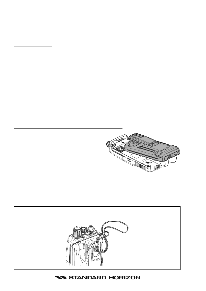
4.3.2 BATTERY INSTALLATION AND REMOVAL
To install the battery pack, hold the
transceiver with your left hand, so your
palm is over the speaker. Insert the battery pack into the battery compartment
on the back of the radio, then push the
bottom side of the battery pack until
the battery pack locks with the Battery
Pack Latch.
To remove the battery, turn the radio off. Slide the Battery Pack Latch on
the bottom of the radio, then lift up on the bottom of the battery and remove
it from the radio.
HAND STRAP INSTALLATION
HX400Page 14
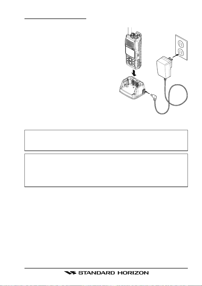
4.3.3 BATTERY CHARGING
1. Turn the transceiver off.
2. Insert the DC plug from the PA-45B into
the DC jack on the CD-50 side panel,
then plug the PA-45B into the AC line
outlet.
3. Insert the HX400 (with the battery pack)
into the CD-50; the antenna should be
at the left side when viewing the charger
from the front.
4. If the HX400 is inserted correctly, the Red
“CHARGING” indicator will glow. A fullydischarged pack will be charged completely in approximately 3 hours.
5. When charging is completed, the red
CD-50
LED indicator will change to green. Remove the transceiver from the CD-50,
and unplug the PA-45B from the AC line outlet.
CAUTION
The CD-50 cradle is NOT designed to be waterproof. Do not attempt to
charge in water hazardous locations.
PA-45B
NOTE
The CD-50 cradle is only designed for the charging of the HX400’s battery, and is not suitable for other purposes. The CD-50 may contribute
noise to TV and radio reception in the immediate vicinity, so we do not
recommend its use adjacent to such device.
Page 15HX400
 Loading...