

Page 1
LAMP
Horizon
HX350S
VHF/FM Marine
Handheld Transceiver
Owner’s Manual
HX350S
N
A
C
S
X
W
M
E
M
16/9
H
/L
A/B
E
L
IB
S
R
E
M
B
U
S
HX350S Owner’s Manual page 23
Page 2

TABLE OF CONTENTS
GENERAL INFORMATION .................................................................................... 1
INTRODUCTION .................................................................................................... 1
FCC/ INDUSTRY CANADA INFORMATION .......................................................... 1
ACCESSORIES ...................................................................................................... 2
PACKING LIST ....................................................................................................... 2
OPTIONS ................................................................................................................2
REPLACEMENT PARTS ........................................................................................ 2
CONTROLS AND INDICATORS............................................................................ 3
CONTROLS AND CONNECTIONS ........................................................................ 3
INDICATORS .......................................................................................................... 6
OPERATION........................................................................................................... 8
INITIAL PROCEDURE ............................................................................................ 8
RECEPTION ........................................................................................................... 8
TRANSMISSION..................................................................................................... 9
TRANSMIT TIME - OUT TIMER (TOT) ................................................................ 10
USA, CANADIAN AND INTERNATIONAL MODES ............................................. 10
NOAA WEATHER CHANNELS ............................................................................ 10
SCAN .................................................................................................................... 11
PRIORITY SCAN .................................................................................................. 11
WEATHER ALERT ............................................................................................... 12
EMERGENCY CHANNEL 16................................................................................ 12
CHANNEL 9 .......................................................................................................... 12
OPERATING ON CHANNEL 13 ........................................................................... 12
OPERATING ON CHANNEL 67 ........................................................................... 13
CHANNEL A/B INSTANT ACCESS ...................................................................... 13
Programming .................................................................................................. 13
Operation ........................................................................................................ 14
SIMPLEX/DUPLEX CHANNEL USE .................................................................... 14
VOICE SCRAMBLER ........................................................................................... 14
Programming .................................................................................................. 14
Operation with voice scrambler ...................................................................... 15
RESETTING THE TRANSCEIVER’S MICROPROCESSOR ............................... 16
BATTERY ............................................................................................................. 17
BATTERY CHARGING ......................................................................................... 17
BATTERY REMOVAL/INSTALLATION ................................................................ 17
OPERATING BATTERY CHARGE SYSTEM ....................................................... 18
CBT350 BATTERY TRAY..................................................................................... 18
BATTERY SAFETY .............................................................................................. 19
MAINTENANCE ................................................................................................... 20
SPECIFICATIONS ................................................................................................ 21
GENERAL ............................................................................................................. 21
TRANSMITTER .................................................................................................... 21
RECEIVER............................................................................................................ 21
page 24 Owner’s Manual HX350S
Page 3

1 GENERAL INFORMATION
1.1 INTRODUCTION
The Standard Communications Corp. (SCC) HX350S is a marine handheld
two-way VHF transceiver. The transceiver has 65 channels: 55 marine and
10 weather. The 55 marine channels are switchable to comply with either
USA, International, or Canadian regulations. It has an emergency channel
16 which can be immediately selected from any channel by pressing the
red 16/9 key. Weather channels can also be accessed immediately by
pressing the WX key.
The transceiver includes the following features: memory scanning, priority
scanning, weather alert, battery saver, easy-to-read large LCD display,
EEPROM memory back-up, battery life displayed on LCD, and a transmit
time-out timer (TOT).
For privacy of communications, an optional CVS240 voice scrambler can
be installed.
1.2 FCC/ INDUSTRY CANADA INFORMATION
The following data pertaining to the transceiver is necessary to fill out the
license application.
FCC Type Accepted........................................................................Part 80
Output Power with
Emission...................................................................................... 16K0F3E
Frequency Range ............................................... 156.025 to 163.275 MHz
FCC Type Number ...................................................................... APV0697
Industry Canada Type Approval ............................................ 363822196A
CNB350/CNB350AS
battery ....... 1 watt
(Low)
and 5 watts
(High)
Additional FCC and Industry Canada data, including licensing
requirements, are contained in the companion document titled
OWNER’S MANUAL SUPPLEMENT. The document also contains
charts for VHF channel assignments, transceiver operating
procedures, maintenance, factory service information, and
warranty data.
HX350S Owner’s Manual page 1
Page 4

2 ACCESSORIES
2.1 PACKING LIST
When the package containing the transceiver is first opened, please check
it for the following contents:
• HX350S Transceiver
• CBT350 Alkaline Battery Tray
• CAW240 DC Charge Cable with 12 V Cigarette Lighter
• CNB350/CNB350AS Rechargeable Battery Pack
• CCA250 Charge Adaptor with screws
• CWC230 120VAC Wall Charger for CCA250
• CAT350 Flexible Antenna with STUD connector
• Lanyard
• Belt Clip with screws
• Owner’s Manual
• Owner’s Manual Supplement
2.2 OPTIONS
CMP350 ....................... Noise-canceling Waterproof Speaker/Microphone
CSA240AB ...... 230VAC Desktop Rapid Charger for CNB350/CNB350AS
CSA280........... 120VAC Desktop Rapid Charger for CNB350/CNB350AS
CVS240.....................................................................Voice Scrambler Unit
CWC232...................................... 120/230 VAC Wall Charger for CCA250
2.3 REPLACEMENT PARTS
Flexible Antenna with STUD Connector ....................................... CAT350
Rechargeable Battery Pack ...................................... CNB350/CNB350AS
Belt Clip..................................................................................484C258012
Screws for Belt Clip................................................................51102604U0
Lanyard .................................................................................. 458C156040
Volume Control Knob ............................................................. 406B154010
Squelch Control Knob ............................................................ 406B154010
SPK/MIC Connector Cover .................................................... 406B067020
SPK/MIC Connector Screw.................................................... 406B010010
SPK/MIC Connector Washer ................................................. 406B012010
page 2 Owner’s Manual HX350S
Page 5

3 CONTROLS AND INDICATORS
NOTE
This section defines each control of the transceiver. For detailed
operating instructions refer to section 4 of this manual.
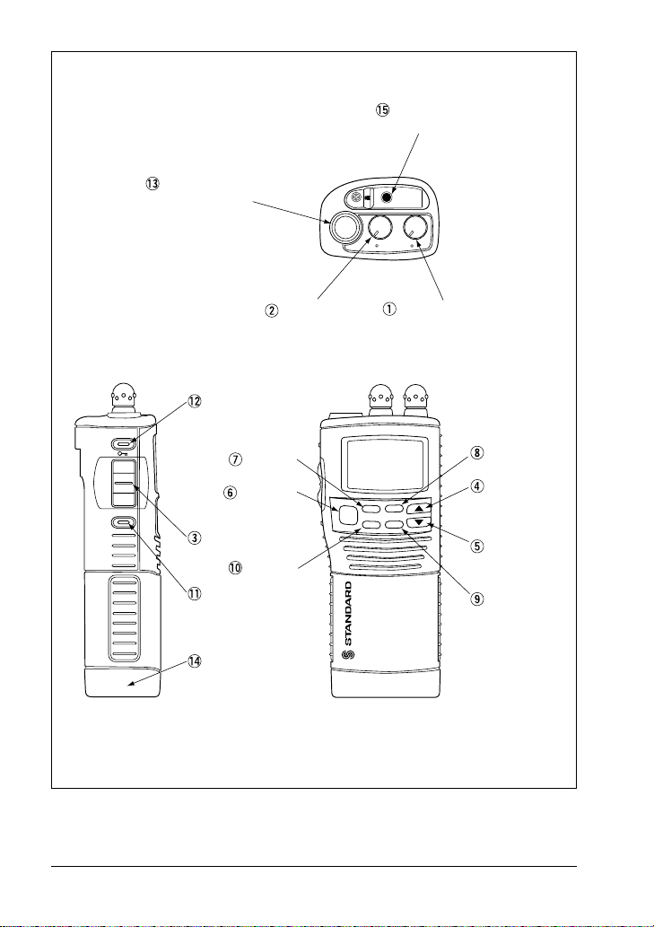
Refer to Figure 1 for the location of the following controls, indicators,
and connections.
3.1 CONTROLS AND CONNECTIONS
q POWER SWITCH/VOLUME CONTROL
Turns the transceiver on and off, and adjusts the volume.
w SQUELCH CONTROL (SQL)
Sets the point at which random noise on the channel does not activate
the audio circuits but a received signal does. This point is called the
squelch threshold. Further adjustment of the squelch control will
degrade the reception of wanted transmissions.
e PUSH-TO-TALK (PTT) SWITCH
Activates transmission.
r UP ( ) KEY
Selects the desired channel. Each press increases the channel
number. When held down, the channels increase continuously.
t DOWN ( ) KEY
Selects the desired channel. Each press decreases the channel
number. When held down, the channels decrease continuously.
y 16/9 KEY
Immediately recalls channel 16 from any channel location. Holding
down this key recalls channel 9. When the WX key is pressed while
holding down this key, the mode toggles between USA, International
and Canadian.
u WX KEY
Immediately recalls a weather channel from any channel location.
Recalls the previous channel when the WX key is pressed again.
HX350S Owner’s Manual page 3
Page 6
ANTENNA
CONNECTOR
SPEAKER/MICROPHONE
CONNECTOR
OFF
VOL
SQL
LAMP
H/L
SQUELCH
CONTROL
POWER SWITCH
VOLUME CONTROL
LAMP/
KEY LOCK KEY
WX KEY
16/9 KEY
HX350S
W
1
6
/9
A
/B
SCAN
X
MEM
PTT SWITCH
A/B KEY
H/L KEY
BATTERY PACK
SUBMERSIBLE
Figure 1. Controls and Connectors
SCAN KEY
UP KEY
DOWN KEY
MEM KEY
page 4 Owner’s Manual HX350S
Page 7

i SCAN KEY
Starts scanning programmed channels. Press this key for at least 1
second to turn on and off priority scan (scanning of programmed
channels and priority channel) during scan.
o MEM (Scrambler) KEY
Memorizes the selected channel. When pressed again, deletes the
memorized channel. Hold down this key for at least 1 second, to turn
the scrambler on and off. (if an optional CVS240 voice scrambler is
installed)
!0 A/B KEY
Immediately recalls two user assigned channels from any channel.
!1 H/L KEY
Toggles between high and low power. To change from low power to
high power, hold down this key on Canadian channel 13, USA channel
13 or 67.
!2 LAMP/ (key lock) KEY
Turns the lamp for LCD and keypad back-lighting on and off.
Hold down this key to lock the displayed channel functions (except the
H/L, PTT and LAMP/
changed. The key lock symbol “
channel is locked. Hold down until the key lock symbol disappears to
unlock the channel.
keys) so that they are not accidentally
” appears to indicate that the
!3 Antenna Connector
Connects the flexible antenna CAT350.
!4 Battery Pack
Provides DC power to the transceiver.
!5 External Speaker/Microphone Jack
Accepts optional CMP350 speaker/microphone. When the EXT jack is
used, the internal speaker is disabled.
HX350S Owner’s Manual page 5
Page 8

3.2 INDICATORS
DISTRESS CALLING
TX
WX
MEM
HL
Figure 2. Indicators
Channel Display
The operating channel in both transmission and reception mode.
A Indicator
Ship-ship channel in USA or Canadian mode whose counterpart in the
International mode is a public corespondence (marine operator) channel.
USA/INTL/CAN Indicator
The modes of operation for the particular channel. “USA” indicates USA
mode. “INTL” indicates International mode and “CAN” indicates Canadian
mode.
TX Indicator
Indicates transmission.
WX Indicator
NOAA weather channel.
MEM Indicator
The channel is in the transceiver’s scan memory.
USA
CAN
INTL
S
H/L Indicator
“H” is high power. “L” is low power. Blank is a reception only channel.
Key Lock Symbol Indicator
The channel is locked. All keys are disabled except for the H/L, PTT and
LAMP/
page 6 Owner’s Manual HX350S
keys.
Page 9

Battery Indicator
Battery life, during transmission and reception, is as follows:
: Over 50% charged
: 25% charged
: Less than 10% charged
: Need to charge (Also see Section 5.1)
NOTE
The battey life indicator is accessed immediately by pressing the PTT
switch.
The battery indicator should be used only as a guide in charging the
CNB350/CNB350AS battery.
S Indicator
S
The small character “
” above the keylock symbol “ ” on the display
indicates the scrambler code. (only when CVS240 scrambler is installed
and activated)
DISTRESS/CALLING Indicator
“DISTRESS/CALLING” indicates CH16 is in use. “CALLING” indicates
CH09 is in use.
HX350S Owner’s Manual page 7
Page 10

4 OPERATION
4.1 INITIAL PROCEDURE
NOTE
Never key the transceiver without an antenna connected. Damage may
occur to the transceiver. Do not operate the transceiver while charging.
1. Install the belt clip on the transceiver if desired. Use the 2 Phillips-head
screws included with the clip to mount the clip to the back of the transceiver.
2. Install the nylon carrying strap on the belt clip if desired.
3. Install the battery pack on the transceiver. (see figure 4 and section 5.2)
4. Install the antenna to the transceiver.
Figure 3. Antenna Installation
5. Turn the POWER /VOLUME CONTROL knob clockwise to turn the
transceiver on.
NOTE
Water resistance of the transceiver is assured only when the battery
pack and antenna are attached to the transceiver.
Turn the battery lock screw clockwise 5 or 6 turns to tighten.
4.2 RECEPTION
1. Turn the POWER /VOLUME CONTROL knob clockwise to turn the
transceiver on.
2. Turn the SQUELCH CONTROL knob fully counterclockwise. This
state is known as squelch off.
3. Turn up the POWER /VOLUME CONTROL knob until the noise or
audio from the speaker is at a desired level.
4. Select a channel that has no signal being received (no one is
transmitting on the channel) and only noise is heard.
5. Slowly turn the SQUELCH CONTROL knob clockwise and stop
immediately after the noise disappears. This condition is known as the
“Squelch Threshold”. If the knob is turned clockwise past this point,
weak signals may not be received. No noise or no signal is heard until
a signal is received that exceeds the squelch threshold.
page 8 Owner’s Manual HX350S
Page 11

6. To change channels, press the or key. Sometimes, a slight
adjustment of the squelch threshold is needed as some channels have
a higher noise level than others.
Please refer to the Owner’s Manual Supplement for a complete listing of
all USA, International and Canadian VHF Marine channels and their use.
7. If necessary, press the LAMP/
automatically turns off in about 5 seconds. To turn off the lamp sooner,
press the LAMP/
8. To lock the channel in the operating mode so that it is not accidentally
changed, hold down the LAMP/
the
and keys and all the front panel controls except the H/L, PTT
and LAMP/ keys. The key lock symbol “ ” appears on the
display to indicate that the channel is locked. Hold down the LAMP/
key for about 1 second to unlock the channel. The key lock symbol
” disappears from display.
“
key again.
key to turn on the lamp. The lamp
key for about 1 second. This locks
4.3 TRANSMISSION
1. Perform steps 1 through 7 of RECEPTION.
2. Before transmitting, monitor the channel and make sure it is clear.
THIS IS AN FCC REQUIREMENT!
3. For communications over short distances, press the H/L key until “L” is
displayed on the LCD. This indicates low power, approximately 1 watt.
NOTE
Transmitting on 1 watt prolongs battery life. Low power (1 watt) should
be selected whenever possible.
4. If using low power is not effective, select high power (5 watts) by
pressing the H/L key until “H” is displayed.
5. When receiving a signal, wait until the signal stops before transmitting.
The transceiver cannot transmit and receive simultaneously.
6. Press the PTT (push - to - talk) switch. The TX indicator is displayed
during transmission.
7. Speak slowly and clearly into the microphone. Hold the microphone
about 1/2 to 1 inch away from your mouth.
8. When the transmission is finished, release the PTT switch.
9. Refer to the OWNER’S MANUAL SUPPLEMENT for standard
transceiver operating procedures.
HX350S Owner’s Manual page 9
Page 12

4.4 TRANSMIT TIME - OUT TIMER (TOT)
While the PTT switch is held down, transmission time is limited to 5
minutes. This prevents prolonged unintentional transmissions. About 10
seconds before automatic transmitter shutdown, a warning beep is
sounded from the speaker. The transceiver automatically switches to the
receiving mode, even if the PTT switch is held down. Before transmitting
again, the PTT switch must first be released and pressed again. This timeout timer (TOT) prevents a continuous transmission that would result from
an accidentally stuck PTT switch.
4.5 USA, CANADIAN AND INTERNATIONAL MODES
1. To change the mode of the transceiver, hold down the 16/9 key and
press the WX key. The mode changes from USA, to International, to
Canadian with each press.
2. “USA” appears on the LCD for the USA mode, “INTL” appears for
International and “CAN” appears in Canadian mode.
3. Refer to marine channel charts in OWNER’S MANUAL
SUPPLEMENT for allocated channels in each mode.
4.6 NOAA WEATHER CHANNELS
1. To receive a weather channel, press the WX key. The transceiver
changes to the weather channel mode.
2. Press the or key to change to other weather channels.
3. To exit from the weather channels, press the WX key. The transceiver
recalls the previous non-weather channel.
page 10 Owner’s Manual HX350S
Page 13

4.7 SCAN
1. Select the desired channel to be scanned using the or key.
2. Press the MEM key to store the channel into the transceiver's
memory. “MEM” is displayed on the LCD.
3. Repeat steps 1 and 2 for all the channels to be scanned.
4. To delete a channel from the transceiver’s scan memory, press the MEM
key again while the memorized channel is displayed. “MEM” disappears.
5. All channels programmed remain in the transceiver’s scan memory
even if the power is turned off. See section “4.17 RESETTING THE
TRANSCEIVER’S MICROPROCESSOR” to clear all the transceiver's
scan memory.
6. Adjust the SQUELCH CONTROL knob until background noise is
eliminated.
7. To start scan, press the SCAN key. The scan proceeds from the
lowest to the highest programmed channel number and stops on
channels when a transmission is received.
8. To stop the scan, press the SCAN key.
4.8 PRIORITY SCAN
1. The following channels can be set as the priority channel; 16, 09, A,
and B. To set the priority channel, hold down the 16/9 key and press
the MEM key. The channel changes from 16 to 09 to A to B channel
with each press of the MEM key. The displayed channel is set to the
priority channel.
2. For priority scanning, hold down the SCAN key at least 1 second
during normal scanning, Scanning will proceed between the
memorized channels and the priority channel. The priority channel will
be scanned after each programmed channel.
3. For example, channels 06, 07, 08 are memorized in the transceiver’s
memory, Priority scanning will proceed in the following sequence:
CH06
Priority
channel
CH07 CH08
Priority
channel
Priority
channel
4. Even when the transceiver stops and listens to the signal of a
programmed channel, the transceiver will dual watch between this
channel and the priority channel.
HX350S Owner’s Manual page 11
Page 14

4.9 WEATHER ALERT
In the event of extreme weather disturbances such as storms and
hurricanes, NOAA (National Oceanic and Atmospheric Administration)
sends a weather alert accompanied by a 1050 Hz tone and subsequent
weather reports on the weather channels. The transceiver is capable of
receiving this alert if the following is performed:
1. Program weather channels into the transceiver’s memory for scanning.
Follow the same procedure as for regular channels under Section 4.7.
2. Press the SCAN key to start the scan.
3. The memorized weather channels are scanned along with the regular
memorized channels. Scan does not stop for normal weather broadcast.
4. When an alert is received on a weather channel, scanning stops and
the transceiver enters the WEATHER ALERT MODE.
5. When the transceiver is in the WEATHER ALERT MODE, a loud tone
is sounded.
6. Press the WX key to stop the alert tone and receive the voice
information on the weather channel.
4.10 EMERGENCY CHANNEL 16
1. To select the emergency channel, press the 16/9 key from any channel.
2. Transmit your emergency signal in the same manner as on regular
channels. If you can not contact anyone on channel 16, switch to
another channel.
3. See the OWNER’S MANUAL SUPPLEMENT for additional
emergency operating practices.
4. To recall the previous channel from 16, press the 16/9 key.
4.11 CHANNEL 9
Channel 9 is used as a hailing channel for initial, non-emergency contact with
other vessels. Hold down the 16/9 key for 1 second to select channel 9.
4.12 OPERATING ON CHANNEL 13
Channel 13 is used at docks, bridges and for maneuvering in port.
Messages on this channel must concern navigation only, such as meeting
and passing in restricted waters.
In emergencies and when approaching blind river bends, high power is
allowed. Hold down the H/L key to temporarily switch to high power. High
power can only be accessed in USA and Canadian modes. When the H/L
key is released, the transceiver will revert low power.
page 12 Owner’s Manual HX350S
Page 15

4.13 OPERATING ON CHANNEL 67
When channel 67 is used for navigational bridge-to-bridge traffic between
ships, high power may be used temporarily in the USA mode by pressing the
H/L key. When the H/L key is released, the transceiver will revert low power.
4.14 CHANNEL A/B INSTANT ACCESS
Two user-assigned channels can be programmed for instant access. USA
channels 9 and 16, and WX channels should not be assigned as A or B
channels because they are readily available with the 16/9 and WX keys. If
the A/B key is pressed and no channel A or B has been assigned, the LCD
will display “– –” and no channel number will be present.
4.14.1 Programming
1. Hold down the A/B key and then turn on the transceiver.
2. The blinking letter A will appear on the display, and dashes “– –”
indicate that no channel has been designated Channel A.
3. Press the
4. With the desired channel number displayed, press the MEM key once.
The “A” will stop blinking, indicating that the displayed channel is now
designated Channel A.
5. Press the A/B key again. The blinking letter “b” will appear on the
display, and dashes “– –” indicate that no channel has been
designated Channel B.
6. Press the
7. With the desired channel number displayed, press the MEM key once.
The “b” will stop blinking, indicating that the displayed channel is now
designated Channel B.
8. Turn the radio off and then on again to return to normal radio mode.
To change A and B channel assignments, perform the following steps:
1. Hold down the A/B key and then turn on the transceiver. The desired
channel A’s number is displayed.
2. Press the MEM key. The “A” will blink and dashes “– –” will appear on
the display.
3. Set the new channel to be designated Channel A (or leave the channel
unassigned). Press the MEM key again to save.
4. Next press the A/B key and press the MEM key. The “b” will blink and
dashes “– –” will appear on the display.
5. Set the new channel to be designated Channel B (or leave the channel
unassigned). Press the MEM key again to save.
6. Turn the radio off and then on again to return to normal radio mode.
or key until the desired channel number is displayed.
or key until the desired channel number is displayed.
HX350S Owner’s Manual page 13
Page 16

4.14.2 Operation
Pressing the A/B key more than once toggles between channel A and
channel B. Channel A is represented by “A” to the left of the channel
number on the LCD, and channel B is represented by “b”. Do not confuse
this “A” with the one that sometimes is displayed to the right of the channel
number (described in the section 3.2 of this Owner’s Manual).
4.15 SIMPLEX/DUPLEX CHANNEL USE
All channels are factory-programmed in accordance with FCC(USA),
Industry Canada and International regulations. Mode of operation cannot
be altered from simplex to duplex or vice-versa. Simplex or duplex mode is
automatically activated, depending on the channel and whether USA,
International or Canadian operating mode is selected. Refer to the channel
charts in the OWNER’S MANUAL SUPPLEMENT.
4.16 VOICE SCRAMBLER
If private communication is desired, a CVS240 voice scrambler can be
installed to the transceiver. Contact your SCC dealer or SCC factory to
have the voice scrambler installed and programmed for your transceiver.
With a voice scrambler installed in the transceiver, channels to be
scrambled can be programmed.
4.16.1 Programming
1. Hold down the WX key and turn on the transceiver.
The display shows:
TX
S
2. Press the
or key to set the scrambler code. There are 128
scrambler codes (00-127).
The display shows:
page 14 Owner’s Manual HX350S
TX
S
Page 17

3. Press the MEM key to store the scrambler code in the transceiver's
memory.
The display shows:
TX
USA
CAN
INTL
S
4. Press the or key to set the scrambled channel (scrambled
channel = CH05).
The display shows:
TX
USA
CAN
INTL
S
5. Press the MEM key to store the scrambled channel in the transceiver.
“MEM” will be displayed on LCD.
TX
MEM
USA
CAN
INTL
S
6. To program other channels to be scrambled, repeat steps 4 and 5.
Only one scrambler code can be chosen for all channels programmed.
4.16.2 Operation with voice scrambler
1. Turn on the transceiver. Normal operation resumes.
2. Select a channel that was programmed for scrambler mode.
3. Hold down the MEM key for 1 second to turn the scrambler on. The
display shows “
4. Hold down the MEM key for 1 second again to turn the scrambler off.
S
” to indicate that the scrambler is activated.
HX350S Owner’s Manual page 15
Page 18

4.17 RESETTING THE TRANSCEIVER’S MICROPROCESSOR
Resetting the microprocessor restores the initial, factory supplied conditions
in the transceiver. These are called the default conditions. To reset the
microprocessor, first turn the transceiver off. Then while holding the WX and
SCAN keys pressed, turn the transceiver on. The default conditions are:
• No channel numbers are in memory.
• Channel 16 is the priority channel.
• Channel 16 will be selected when the transceiver is turned on.
• WX channel 01 will be recalled when the WX key is pressed.
• Channels A and B are unassigned.
• No voice scrambler code is selected.
NOTE
The above procedure also resets the microprocessor. Perform this
procedure if an operational problem occurs.
page 16 Owner’s Manual HX350S
Page 19

5 BATTERY
CAUTION
To avoid risk of explosion and injury,
only be removed, charged or recharged in non-hazardous environments.
5.1 BATTERY CHARGING
To check the charge status, install the battery and press the PTT switch
while observing the BATT indicator. (see page 7)
The battery charge system (CCA250 and CWC230) supplied with the
transceiver recharges a completely discharged CNB350/CNB350AS
battery pack in about 15 hours.
Battery pack should not be charged with the supplied battery charge
system for longer than 16 hours.
The CSA280 is an optional desktop rapid charger that charges the CNB350/
CNB350AS battery pack in approximately 1.5 hours. The transceiver and its
battery can be placed into this charger, and the charger set to rapid charge.
Battery condition is automatically sensed: when full charge is achieved, the
charger switches to trickle-charge mode to maintain the charge indefinitely
without harm to either the battery or the charger. This charger and an extra
battery are highly recommended.
5.2 BATTERY REMOVAL/INSTALLATION
Figure 4. Installing the battery
CNB350/CNB350AS
1. Turn the transceiver off.
2. To remove, turn the battery lock screw
counterclockwise 5 or 6 turns, and pull
the battery pack until it slides out.
3. To install, slide the battery pack into
the battery cavity until fully inserted,
and turn the battery lock screw
clockwise until hand-tightened. (see
figure 4)
battery pack should
HX350S Owner’s Manual page 17
Page 20

5.3 OPERATING BATTERY CHARGE SYSTEM
1. Plug the end of CWC230 wall charger to the DC IN connector of the
CCA250 charge adaptor.
2. Plug the wall charger into a 120 VAC wall outlet.
3. Turn the transceiver off.
4. Insert the transceiver. The indicator lights, and charging begins.
5. Remove the battery pack from charge adaptor when charging time has
passed.
NOTE
The CWC230 can be replaced by the CAW240 mobile cable, or
CWC232 120/230 VAC wall charger.
CAUTION
Never plug the power supply to the CCA250 charge adaptor except
with a CAW240, CWC230 or CWC232.
5.4 CBT350 BATTERY TRAY
CBT350 is a battery tray that holds six AA alkaline batteries and is used
with the HX350S transceiver.
1. Push both sides of the top case and remove the bottom case.
2. Install the battery cells into the top case, paying close attention to the
battery polarity markings on the case.
n When the HX350S is operated with the alkaline batteries, the battery
life is as follows: (5/5/90 duty cycle)
• high power - 5 hours
• low power - 12 hours
Note that battery life is more than doubled if transceiver is consistently
operated on low power.
NOTE
To ensure proper alignment of screw, rotate it counterclockwise a
couple of times prior to tightening.
The battery indicator on the transceiver is only applicable to the
CNB350/CNB350AS rechargeable battery. Disregard this indication
when using alkaline batteries.
page 18 Owner’s Manual HX350S
Page 21

5.5 BATTERY SAFETY
Battery packs for your transceiver contain Nickel-cadmium (Ni-Cd)
batteries. This type of battery stores a charge powerful enough to be
dangerous if misused or abused, especially when removed from the
transceiver. Please observe the following precautions:
DO NOT SHORT BATTERY PACK TERMINALS
Shorting the terminals that power to the transceiver can cause sparks,
severe overheating, burns, and battery cell damage. If the short is of
sufficient duration, it is possible to melt battery components. Do not place a
loose battery pack on or near metal surfaces or objects such as paper clips,
keys, tools, etc. When the battery pack is installed on the transceiver, the
terminals that transfer current to the transceiver are not exposed. The
terminals that are exposed on the battery pack when it is mounted on the
transceiver are charging terminals only and do not constitute a hazard.
DO NOT OVERCHARGE
Do not charge the transceiver for more than 16 hours with the battery
charge system. Heat generated by overcharging can shorten battery life
and cause other battery pack component failures. The CSA280 rapid
charger changes to trickle charge to maintain charge after their rapid
charge cycle. Battery packs may be left in the CSA280 chargers without
harm to either the battery pack or charger.
DO NOT INCINERATE
Do not dispose of any Ni-Cd battery in a fire or incinerator. The heat of fire
may cause battery cells to explode and/or release dangerous gases.
DISPOSE OF BATTERY PACKS PROPERLY
Ni-Cd batteries must be recycled or disposed of properly. For requirements
in your area, check with the dealer from whom you purchased your
transceiver. The symbol shown below is a reminder that the battery packs
are recyclable.
Ni - Cd
HX350S Owner’s Manual page 19
Page 22

6 MAINTENANCE
For preventive maintenance and instructions on obtaining factory service,
please refer to the OWNER’S MANUAL SUPPLEMENT. For general
troubleshooting, refer to this Troubleshooting Chart.
TROUBLESHOOTING CHART
SYMPTOM
PROBABLE
CAUSE
REMEDY
The SCAN key
does not start the
scan.
The USA/INTL/CAN
modes do not
function.
Rotating the
squelch control
does not eliminate
background noise.
Cannot change any
function.
Key Lock does not
function.
LED on CCA250 or
CWC230 does not
light when charging
a battery.
No channels
memorized.
Squelch is not
adjusted.
Proper operation
not followed.
Low battery.
Key Lock is on.
Proper operation
not followed.
Defective battery,
CCA250 or
CWC230.
Use the MEM key to enter
desired channels into the
transceiver’s memory.
Adjust the squelch to threshold or to the point where
noise just disappears. Further
adjustment of the squelch
control may eliminate
incoming signals.
Hold down the 16/9 key and
press the WX key.
Charge battery. Refer to
section 5 of this manual.
Turn Key Lock off.
Hold down for 1 second.
Contact your SCC dealer or
SCC for servicing.
page 20 Owner’s Manual HX350S
Page 23

7 SPECIFICATIONS
Performance specifications are nominal, unless otherwise indicated, and
are subject to change without notice.
7.1 GENERAL
Frequency Range ............................................... 156.025 to 163.275 MHz
Channels ................................. All currently allocated USA, Canadian and
International channels, plus 10 weather channels.
RF Power Output with
Operating Voltage ......................................................................... 7.2 VDC
Current Drain:
Standby ..................................................................................... 40 mA
Receive ................................................................................... 200 mA
Transmit ................................... 1.8 A (high power), 0.7 A (low power)
Dimensions...............................................5.51” H x 2.17” W x 1.50” D
Weight ........................................................................1.0 Ib. (0.45 Kg)
FCC Type Acceptance Number ........................................... APV0697
Industry Canada Type Approval Number ........................ 363822196A
Battery Life(5% TX, 5% RX, 90% Standby) ................... 10 hrs. (high)
CNB350/CNB350AS
7.2 TRANSMITTER
Conducted Spurious Emissions ..........................65 dB (high); 55 dB (low)
Audio Response........................ within +2/-8 of 6 dB/octave pre-emphasis
AF Harmonic Distortion ........................................................................ 3 %
Hum and Noise ................................................................................. 37 dB
Frequency Stability (-20° to +50°C) ....................................... +/- 0.0005 %
Battery........ 5.0 W
(140.0 mm x 55 mm x 38 mm)
characteristic from 300 Hz to 3000 Hz
(high)
1.0 W
15 hrs. (low)
(low)
7.3 RECEIVER
Sensitivity:
20 dB Quieting ........................................................................ 0.35 µV
12 dB SINAD........................................................................... 0.30 µV
Squelch Sensitivity (Threshold) ..................................................... 0.20 µV
Modulation Acceptance Bandwidth ........................................... +/- 4.5 kHz
Selectivity:
Spurious and Image Rejection ................................................... 60 dB
Intermodulation Rejection .......................................................... 60 dB
Channel Spacing ...................................................................... 25 kHz
HX350S Owner’s Manual page 21
Page 24

Standard Communication Corp.
P.O. Box 92151
Los Angeles, CA 90009-2151
Telephone 310/532-5300
© STANDARD COMMUNICATIONS CORP. 1999
All Rights Reserved
Printed in Japan
03/99 406B851012
page 22 Owner’s Manual HX350S
 Loading...