

Standard Horizon HX300E Owner's Manual
Page 1HX300E
HX300E
Floating VHF FM Marine Transceiver
Owner’s Manual

HX300EPage 2
TABLE OF CONTENTS
Quick Reference Guide .................................................................................................................................... 3
1. GENERAL INFORMATION ........................................................................................................................ 4
1.1 INTRODUCTION............................................................................................................................ 4
1.2 RF EXPOSURE SAFETY STATEMENT ........................................................................................ 4
2. ACCESSORIES .......................................................................................................................................... 5
2.1 PACKING LIST .............................................................................................................................. 5
2.2 OPTIONS ....................................................................................................................................... 5
3. ABOUT THIS RADIO ................................................................................................................................ 6
3.1 ABOUT THE VHF MARINE BAND ............................................................................................ 6
3.2 ABOUT WATER RESISTANCE ................................................................................................... 6
3.3 DISTRESS AND HAILING (CHANNEL 16) ................................................................................ 6
3.4 CALLING ANOTHER VESSEL (CHANNEL 16 OR 9) ............................................................... 7
3.5 OPERATING ON CHANNEL 13 AND 67 (USA Channel Group Only) ..................................... 8
3.6 SIMPLEX / DUPLEX CHANNEL USE .......................................................................................... 8
4. GETTING STARTED................................................................................................................................ 10
4.1 RADIO CARE ............................................................................................................................... 10
4.2 BATTERIES AND CHARGERS .................................................................................................. 10
4.2.1 BATTERY SAFETY ..........................................................................................................11
4.2.2 BATTERY INSTALLATION / REMOVAL .......................................................................... 12
4.2.3 BATTERY CHARGING .................................................................................................... 13
4.3 BELT CLIP INSTALLATION / REMOVAL ................................................................................... 14
HAND STRAP INSTALLATION .................................................................................................. 14
4.4 INSTALLATION OF OPTION ..................................................................................................... 15
4.4.1 FBA-44 ALKALINE BATTERY CASE ............................................................................ 15
5. CONTROLS AND INDICATORS ............................................................................................................ 16
5.1 CONTROLS AND SWITCHES ................................................................................................... 16
5.2 LCD INDICATORS ...................................................................................................................... 19
6. BASIC OPERATION ................................................................................................................................ 21
6.1 INITIAL SETUP ........................................................................................................................... 21
6.2 RECEPTION ................................................................................................................................ 21
6.3 TRANSMISSION .......................................................................................................................... 22
6.3.1 TRANSMIT TIME-OUT TIMER (TOT) .............................................................................. 22
WATER ENABLED LIGHT ........................................................................................................... 22
6.4 USA, CANADIAN, AND INTERNATIONAL CHANNELS .......................................................... 23
6.5 KEYPAD LOCKING ..................................................................................................................... 23
6.6 PRESET CHANNELS (0 ~ 9): INSTANT ACCESS ................................................................... 23
6.6.1 PROGRAMMING ............................................................................................................. 23
6.6.2 OPERATION ..................................................................................................................... 24
6.6.3 DELETING A PRESET CHANNEL ................................................................................ 24
6.7 SCANNING .................................................................................................................................. 24
6.7.1 PROGRAMMING SCAN MEMORY ............................................................................... 24
6.7.2 SELECTING SCAN TYPE .............................................................................................. 25
6.7.3 OPERATION ..................................................................................................................... 26
6.7.3.1 Priority Scan ....................................................................................................... 26
6.7.3.2 Memory Scan ..................................................................................................... 26
6.8 DUAL WATCH ............................................................................................................................. 27
6.9 TRI-WATCH ................................................................................................................................. 28
7. ATIS SETUP ............................................................................................................................................. 29
7.1 ATIS CODE PROGRAMMING ..................................................................................................... 29
7.2 ATIS CH GROUP ......................................................................................................................... 30
8. MENU (“SET”) MODE .............................................................................................................................. 31
9. MAINTENANCE ........................................................................................................................................ 33
9.1 GENERAL .................................................................................................................................... 33
9.2 REPLACEMENT PARTS............................................................................................................. 33
9.3 TROUBLESHOOTING CHART ................................................................................................... 33
10. VHF MARINE CHANNEL ASSIGNMENT ............................................................................................. 34
11. SPECIFICATIONS .................................................................................................................................... 38
11.1 GENERAL .................................................................................................................................... 38
11.2 TRANSMITTER............................................................................................................................ 38
11.3 RECEIVER ................................................................................................................................... 38
Page 3HX300E
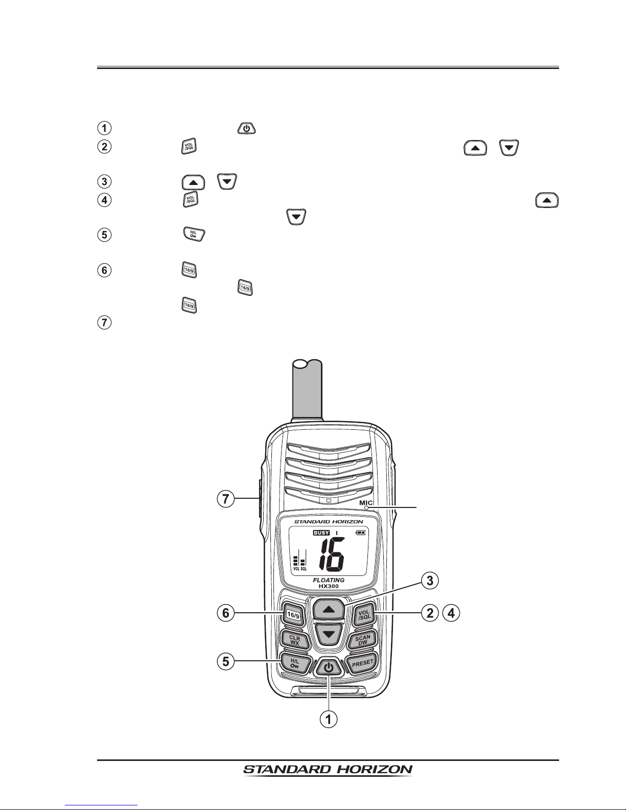
Quick RefeRence Guide
This transceiver is equipped with the E2O (Easy-To-Operate) system. You
can do the basic operation in numerical order of the illustration below.
Press and hold the key to turn on or off the radio.
Press the key (“VOL” indicator blinks), then press the / key to
adjust the speaker audio volume.
Press the / key to selects the operating channel.
Press the key two times (“SQL” indicator blinks), then press the
key to squelch or press the key to un-squelch the radio.
Press the key to toggle the transmit power between High (5W) and
Low (1W).
Press the key briey to recall channel 16.
Press and hold the
key for two seconds to recall channel 9.
Press the
key again to revert to the last selected channel.
Place your mouth about 2.5 cm away from MIC hole and speak in a nor-
mal voice level while pressing the PTT switch.
MIC Hole

HX300EPage 4
1. GENERAL INFORMATION
1.1 INTRODUCTION
The HX300E is a Submersible Floating 5-Watt portable two way marine
transceiver. The transceiver has all allocated USA, International, or Canadian
channels. It has emergency channel 16 which can be immediately selected
from any channel by pressing the
key.
The HX300E includes the following features: Memory Scanning, Priority
Scanning, Dual and Tri-watch, easy-to-read large LCD display, Battery Life
displayed on LCD, the Water Enabled Light which blinks automatically when
the radio comes in contact with water even if the radio is turned off, and a
transmit Time-Out Timer (TOT).
The HX300E transmitter provides a full 5 Watt of transmit power and also is
selectable to 1 Watt to assist the user in ensuring maximum battery life.
The HX300E supports ATIS mode which is used in the inland waterways of
Europe. Please contact your local PTT administration or Marine Authority to
obtain your ATIS number.
We appreciate your purchase of the HX300E, and encourage you to read
this manual thoroughly, so as to learn and fully understand the capabilities of
the HX300E.
1.2 RF EXPOSURE SAFETY STATEMENT
Your wireless handheld portable transceiver contains a low power transmitter. When the Push-to-Talk (PTT) button is pushed, the transceiver sends out
radio frequency (RF) signals.
This device is authorized to operate at a maximum duty factor not to exceed
2:1 (this corresponds to 50% transmission time and 50% reception time), but
normal usage should not exceed 3:1 (25% transmission time and 75% reception/standby time).
This transmitter and its antenna must maintain a separation distance of at
least 2.5 cm from your face. Speak in a normal voice, with the antenna pointed up and away from the face at the required separation distance.
Use only the supplied antenna. Unauthorized antennas, modications, or attachments could damage the transmitter.
Page 5HX300E
2. ACCESSORIES
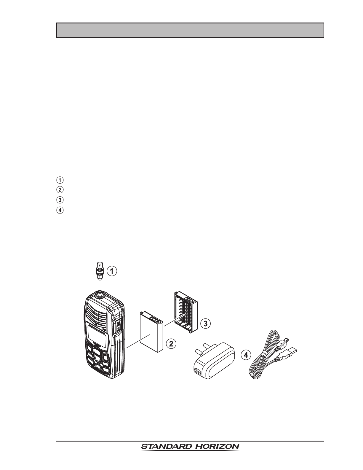
2.1 PACKING LIST
When the package containing the transceiver is rst opened, please check it
for the following contents:
HX300E Transceiver
CAT460 Antenna
FNB-122LI 3.7 V, 1560 mAh Li-ion Battery Pack
PA-54C/U
USB Wall Charger (100 - 240 VAC) and Cable
CLIP-22 Belt Clip
Hand Strap
Owner’s Manual
Warranty Card
2.2 OPTIONS
CN-3 Radio-to-Ship’s-Antenna Adapter
FNB-122LI 3.7 V, 1560 mAh Li-ion Battery Pack
FBA-44 Alkaline Battery Case (3 x “AAA” Cell Size)
PA-54B/C/U USB Wall Charger and Cable
:
“B” sufx has a Type-A plug, “C” sufx has a Type-C plug, and “U” sufx
has a Type-BF plug. All versions of the USB Wall Charger are available in
100-240 VAC.
Note: Before operating the HX300E for the rst time, it is recommended that
the battery be charged. Please see section “4.2.3 BATTERY CHARGING”
for details.

HX300EPage 6
3. ABOUT THIS RADIO
3.1 ABOUT THE VHF MARINE BAND
The radio frequencies used in the VHF marine band lie between 156 and
158 MHz. The marine VHF band provides communications over distances
that are essentially “Line of sight” Actual transmission range depends much
more on antenna type, gain and height than on the power output of the transmitter. On a xed mount 25 W radio transmission expected distances can be
greater than 25 km, for a portable radio transmission the expected distance
can be greater than 8 km in “Line of sight”.
The user of a Marine VHF radio is subject to severe nes if the radio is used
on land. The reasoning for this is you may be near an inland waterway, or
propagation anomalies may cause your transmission to be heard in a waterway. If this occurs, depending upon the marine VHF channel on which you
are transmitting, you could interfere with a search and rescue case, or contribute to a collision between passing ships. For VHF Marine channel assignments refer to section “10. VHF MARINE CHANNEL ASSIGNMENT”.
3.2 ABOUT WATER RESISTANCE
The HX300E is only submersible※ when the Battery Cover is latched and the
Charge (CHG) Cover is snapped closed.
※
IPX8 Specication for submersibility: 1.5 m for 30 minutes.
3.3 DISTRESS AND HAILING (CHANNEL 16
)
Channel 16 is known as the Hail and Distress Channel. An emergency may
be dened as a threat to life or property. In such instances, be sure the transceiver is on and set to “Channel 16”. Then use the following procedure:
1. Press the PTT (Push-To-Talk) switch and say “Mayday, Mayday, May-
day. This is _____, _____, _____” (your vessel’s name).
2. Then repeat once: “Mayday, _____” (your vessel’s name).
3. Now report your position in latitude/longitude, or by giving a true or magnetic bearing (state which) to a well-known landmark such as a navigation aid or geographic feature such as an island or harbor entry.
4. Explain the nature of your distress (sinking, collision, aground, re, heart
attack, life-threatening injury, etc.).
5. State the kind of assistance your desire (pumps, medical aid, etc.).
6. Report the number of persons aboard and condition of any injured.
7. Estimate the present seaworthiness and condition of your vessel.
8. Give your vessel’s description: length, design (power or sail), color and
other distinguishing marks. The total transmission should not exceed 1

Page 7HX300E
minute.
9. End the message by saying “OVER”. Release the PTT switch and listen.
10. If there is no answer, repeat the above procedure. If there is still no response, try another channel.
3.4 CALLING ANOTHER VESSEL (CHANNEL 16 OR 9
)
Channel 16 may be used for initial contact (hailing) with another vessel.
However, its most important use is for emergency messages. This channel
must be monitored at all times except when actually using another channel.
It is monitored by the U.S. and Canadian Coast Guards and by other vessels. Use of channel 16 for hailing must be limited to initial contact only. Calling should not exceed 30 seconds, but may be repeated 3 times at 2-minute
intervals. In areas of heavy radio trafc, congestion on channel 16 resulting
from its use as a hailing channel can be reduced signicantly in U.S. waters
by using Channel 9 as the initial contact (hailing) channel for non-emergency
communications. Here, also, calling time should not exceed 30 seconds but
may be repeated 3 times at 2-minute intervals.
Prior to making contact with another vessel, refer to the channel charts in this
manual, and select an appropriate channel for communications after initial
contact. For example, Channels 68 and 69 of the U.S. VHF Charts are some
of the channels available to non-commercial (recreational) boaters. Monitor
your desired channel in advance to make sure you will not be interrupting
other trafc, and then go back to either channel 16 or 9 for your initial contact.
When the hailing channel (16 or 9) is clear, state the name of the other vessel you wish to call and then “this is” followed by the name of your vessel
and your Station License (Call Sign). When the other vessel returns your
call, immediately request another channel by saying “go to”, the number of
the other channel, and “over”. Then switch to the new channel. When the
new channel is not busy, call the other vessel.
After a transmission, say “over”, and release the PTT (Push-To-Talk) switch.
When all communication with the other vessel is completed, end the last
transmission by stating your Call Sign and the word “out”. Note that it is not
necessary to state your Call Sign with each transmission, only at the beginning and end of the contact.
Remember to return to Channel 16 when not using another channel. Some
radios automatically monitor Channel 16 even when set to other channels or
when scanning.
HX300EPage 8
3.5 OPERATING ON CHANNELS 13 AND 67
(USA Channel Group Only)
Channel 13 is used at docks and bridges and by vessels maneuvering in
port. Messages on this channel must concern navigation only, such as meeting and passing in restricted waters.
Channel 67 is used for navigational trafc between vessels.
By regulation, power is normally limited to 1 Watt on these channels. Your radio is programmed to automatically reduce power to this limit on these channels. however, in certain situations it may be necessary to temporarily use a
higher power.
Pressing the
key will change the power output from Low Power (1 Watt)
to High (5 Watts). When you change from this channel then return to it, low
power will be automatically selected.
3.6 SIMPLEX/DUPLEX CHANNEL USE
Refer to the section “10. VHF MARINE CHANNEL ASSIGNMENT” for instructions on use of simplex and duplex channels.
NOTE
All channels are factory-programmed in accordance with FCC (USA),
Industry Canada and International regulations. The mode of operation cannot be altered from simplex to duplex or vice-versa. Simplex
(ship to ship) or duplex (marine operator) mode is automatically activated, depending on the channel and whether the USA, International
or Canadian operating band is selected.

Page 9HX300E
MEMO
HX300EPage 10
4. GETTING STARTED
4.1 RADIO CARE
CAUTION
Before following the instructions below, insure the battery pack is in
place and the cover is latched. Care must be taken if the radio was
dropped and a close inspection may be needed to insure the radio
case and gaskets are in adequate condition.
After using the HX300E in salt water environment is recommended to clean
the radio with fresh by rinsing the radio under a sink faucet or by dunking the
radio in a bucket of fresh water. After washing, use a soft cloth and thoroughly dry all parts of the radio. This is to keep the rubber switches and speaker
grill clean and in top operating condition.
4.2 BATTERIES AND CHARGERS
If the radio has never been used, or its charge is depleted, it may be charged
by connecting the PA-54C/U USB Wall Charger with the Charge Cable, see
section “4.2.3 BATTERY CHARGING”. The PA-54C/U will charge a com-
pletely discharged FNB-122LI battery pack in about 6 hours.
If the USB port is available (such as your personal computer), You may
charge the FNB-122LI battery pack by connecting the supplied Charge Cable between the HX300E and USB port.
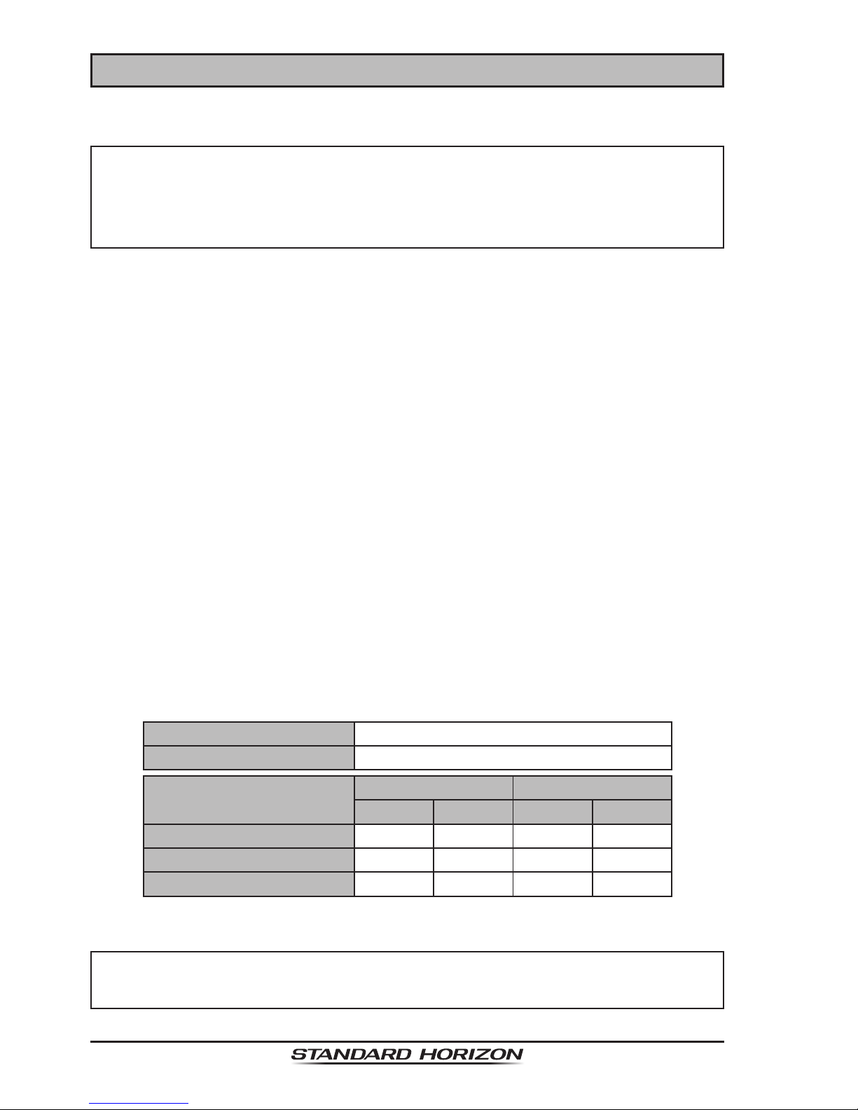
The FNB-122LI is a high performance Li-ion battery providing high capacity
in a compact package.
FNB-122LI Rechargeable Battery Pack
Capacity 1560 mAh
Nominal Voltage 3.7 V
Temperature Range
Minimum Maximum
°C °F °C °F
Charge 5 41 35 95
Discharge –20 –4 60 140
Storage
–10 14 35 95
CAUTION
To avoid risk of explosion and injury, FNB-122LI battery pack should
only be removed, charged or recharged in non-hazardous environments.

Page 11HX300E
4.2.1 BATTERY SAFETY
Battery packs for your transceiver contain Li-ion batteries. This type of battery stores a charge powerful enough to be dangerous if misused or abused,
especially when removed from the transceiver. Please observe the following
precautions:
DO NOT SHORT BATTERY PACK TERMINALS: Shorting the terminals
that power the transceiver can cause sparks, severe overheating, burns, and
battery cell damage. If the short is of sufcient duration, it is possible to melt
battery components. Do not place a loose battery pack on or near metal surfaces or objects such as paper clips, keys, tools, etc. When the battery pack
is installed on the transceiver, the terminals that transfer current to the transceiver are not exposed. The terminals that are exposed on the battery pack
when it is mounted on the transceiver are charging terminals only and do not
constitute a hazard.
DO NOT INCINERATE: Do not dispose of any battery in a re or incinerator.
The heat of re may cause battery cells to explode and/or release dangerous
gases.
Battery Maintenance
For safe and proper battery use, please observe the following:
Battery packs should be charged only in non-hazardous environments;
Use only STANDARD HORIZON-approved batteries;
Exceeding the specied temperature limits;
Reversing charge polarity. Use only the proper charger. If this is tam-
pered with or another charger is used, permanent damage may result;
Use only a STANDARD HORIZON approved charger. The use of any
other charger may cause permanent damage to the battery.
Follow charging instructions provided with the chargers.
Submersing the battery in water, or attempting to open the battery casing.
Keep the battery contacts clean.
Battery Storage
When a battery pack is not used for a long time, please remove it from the
transceiver. Also, while in storage, the charge will drain slightly over time and
the battery should be recharged each six months.
Store the batteries in a cool place to maximize storage life. Since batteries are
subject to self-discharge, avoid high storage temperatures that cause large
self-discharge rates. After extended storage, a full recharge is recommended.
HX300EPage 12
Battery Recycling
DO NOT PLACE USED BATTERIES IN YOUR REGULAR TRASH!
LI-ION BATTERIES MUST BE COLLECTED, RECYCLED
OR DISPOSED OF IN AN ENVIRONMENTALLY SOUND
MANNER.
The incineration, land lling or mixing of Li-ion batteries with the municipal
solid waste stream is PROHIBITED BY LAW in most areas.
Return batteries to an approved Li-ion battery recycler. This may be where
you purchased the battery.
Contact your local waste management ofcials for other information regarding the environmentally sound collection, recycling and disposal of Li-ion batteries.
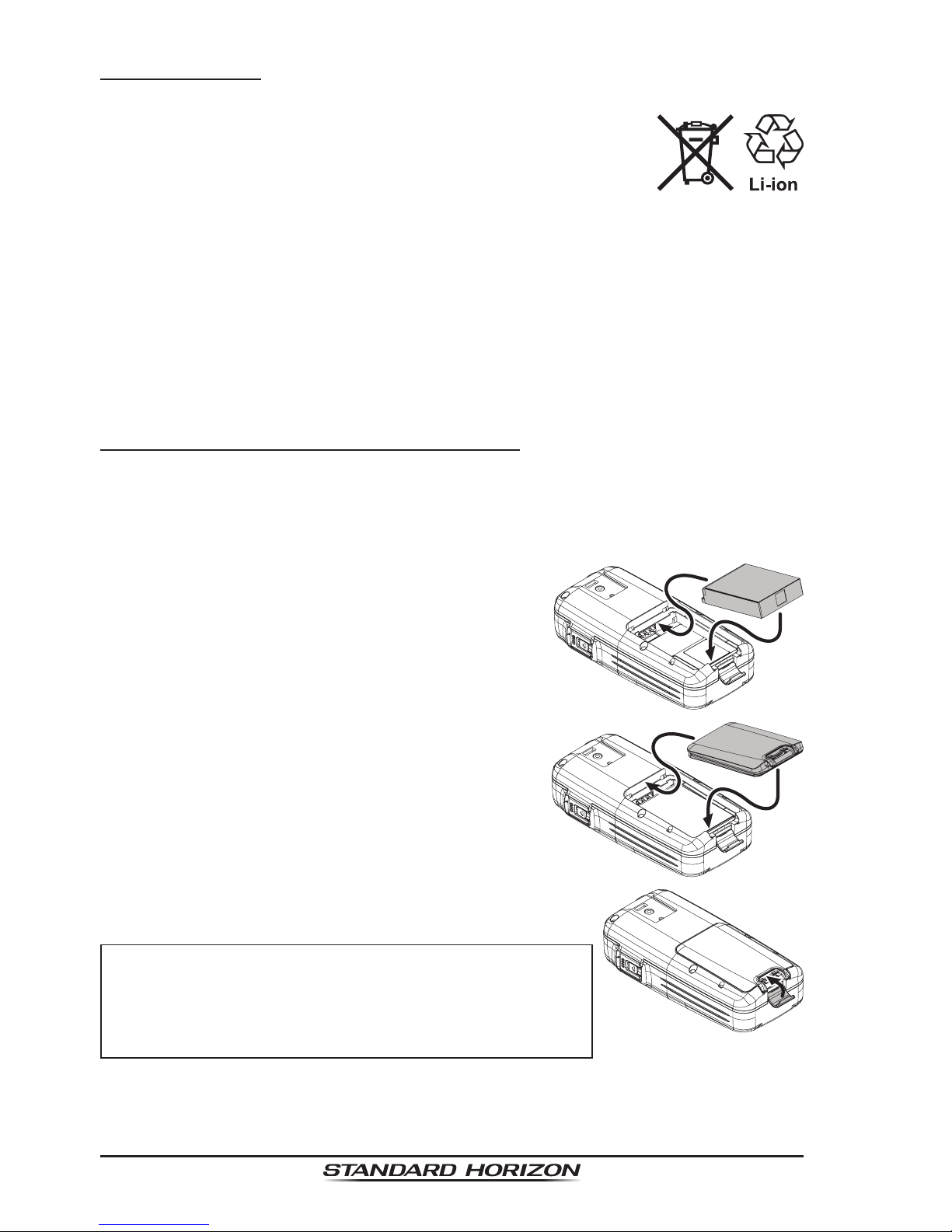
4.2.2 BATTERY INSTALLATION / REMOVAL
Open the Battery Cover Latch on the bottom of the radio, then remove
the Battery Cover from the radio while pulling the bottom side of the Battery Cover.
Install the FNB-122LI Battery Pack into the radio, by carefully mating the
battery’s two alignment tabs on the top side
of the Battery Pack with their corresponding
alignment slots in the Battery Nest of the radio, then gently press the bottom side of the
Battery Pack until it locks in place.
Install the Battery Cover by carefully align-
ing the two tabs on the top of the cover with
the slots on the radio, then gently press the
bottom side of the Battery Cover. Confirm
that a Rubber Gasket of the Battery Cover
is installed correctly.
Close the Battery Cover Latch until it locks
in place with a “Click”.
CAUTION
To insure the HX300E will not have a problem
with water intrusion, make sure the battery
cover is properly installed and the battery
latch is closed.
 Loading...