

Standard Horizon HX290E Owner's Manual
Page 1HX290E
HX290E
Floating Marine Transceiver
Owner ’s Manual

HX290EPage 2
TABLE OF CONTENTS
QUICK REFERENCE GUIDE........................................................................................................3
1. GENERAL INFORMATION ....................................................................................................4
1.1 INTRODUCTION ......................................................................................................... 4
1.2 RF EXPOSURE SAFETY STATEMENT................................................................... 4
2. ACCESSORIES ...................................................................................................................... 5
2.1 PACKING LIST ........................................................................................................... 5
2.2 OPTIONS ..................................................................................................................... 5
3. ABOUT THIS RADIO ............................................................................................................6
3.1 ABOUT THE VHF MARINE BAND .......................................................................... 6
3.2 ABOUT WATER RESISTANCE ................................................................................. 6
3.3 DISTRESS AND HAILLING (CHANNEL 16)............................................................ 6
3.4 CALLING ANOTHER VESSEL (CHANNEL 16 OR 9)............................................ 7
3.5 OPERATING ON CHANNEL 13 ............................................................................... 8
3.6 OPERATING ON CHANNEL 67 ............................................................................... 8
3.7 SIMPLEX/DUPLEX CHANNEL USE ......................................................................... 8
4. GETTING ST ARTED............................................................................................................10
4.1 RADIO CARE ............................................................................................................ 10
4.2 BELT CLIP INSTALLATION AND REMOVAL ........................................................ 10
4.3 BATTERIES AND CHARGERS ............................................................................... 11
4.3.1 BATTERY SAFETY ....................................................................................... 11
4.3.2 BATTERY INSTALLATION / REMOVAL ....................................................... 12
4.3.3 BATTERY CHARGING .................................................................................13
5. CONTROLS AND INDICATORS.........................................................................................14
5.1 CONTROLS AND SWITCHES ................................................................................ 14
5.2 LCD INDICATORS .................................................................................................... 17
6. BASIC OPERA TION ............................................................................................................18
6.1 PROHIBITED COMMUNICATIONS ......................................................................... 18
6.2 INITIAL SETUP ......................................................................................................... 18
6.3 RECEPTION ..............................................................................................................18
6.4 TRANSMISSION .......................................................................................................19
6.4.1 TRANSMIT TIME-OUT TIMER (TOT)........................................................... 19
6.5 INTERNATIONAL, CANADIAN, AND USA CHANNELS ........................................20
6.6 KEYPAD LOCKING .................................................................................................. 20
6.7 PRESET CHANNELS (0 ~ 9): INSTANT ACCESS ................................................ 21
6.7.1 PROGRAMMING .......................................................................................... 21
6.7.2 OPERATION ................................................................................................. 21
6.8 SCANNING ................................................................................................................22
6.8.1 SELECTING THE SCAN TYPE .................................................................... 22
6.8.2 PROGRAMMING SCAN MEMORY ............................................................ 23
6.8.3 MEMORY SCANNING (M-SCAN)................................................................ 23
6.8.4 PRIORITY SCANNING (P-SCAN)................................................................ 23
6.9 DUAL WATCH ...........................................................................................................24
7. A TIS SETUP..........................................................................................................................26
7.1 ATIS CODE PROGRAMMING ................................................................................... 26
7.2 ATIS CH GROUP .......................................................................................................27
8. MENU (“SET”) MODE .......................................................................................................... 28
9. MAINTENANCE ....................................................................................................................30
9.1 GENERAL .................................................................................................................. 30
9.2 REPLACEMENT PARTS .......................................................................................... 30
9.3 TROUBLESHOOTING CHART ................................................................................ 31
10. VHF MARINE CHANNEL ASSIGNMENT ..........................................................................32
11 . INST ALLATION OF OPTION ..............................................................................................36
11.1 FBA-42 ALKALINE BATTERY CASE ........................................................................ 36
12. SPECIFICATIONS.................................................................................................................37
12.1 GENERAL .................................................................................................................. 37
12.2 TRANSMITTER ......................................................................................................... 37
12.3 RECEIVER ................................................................................................................ 37
Page 3HX290E
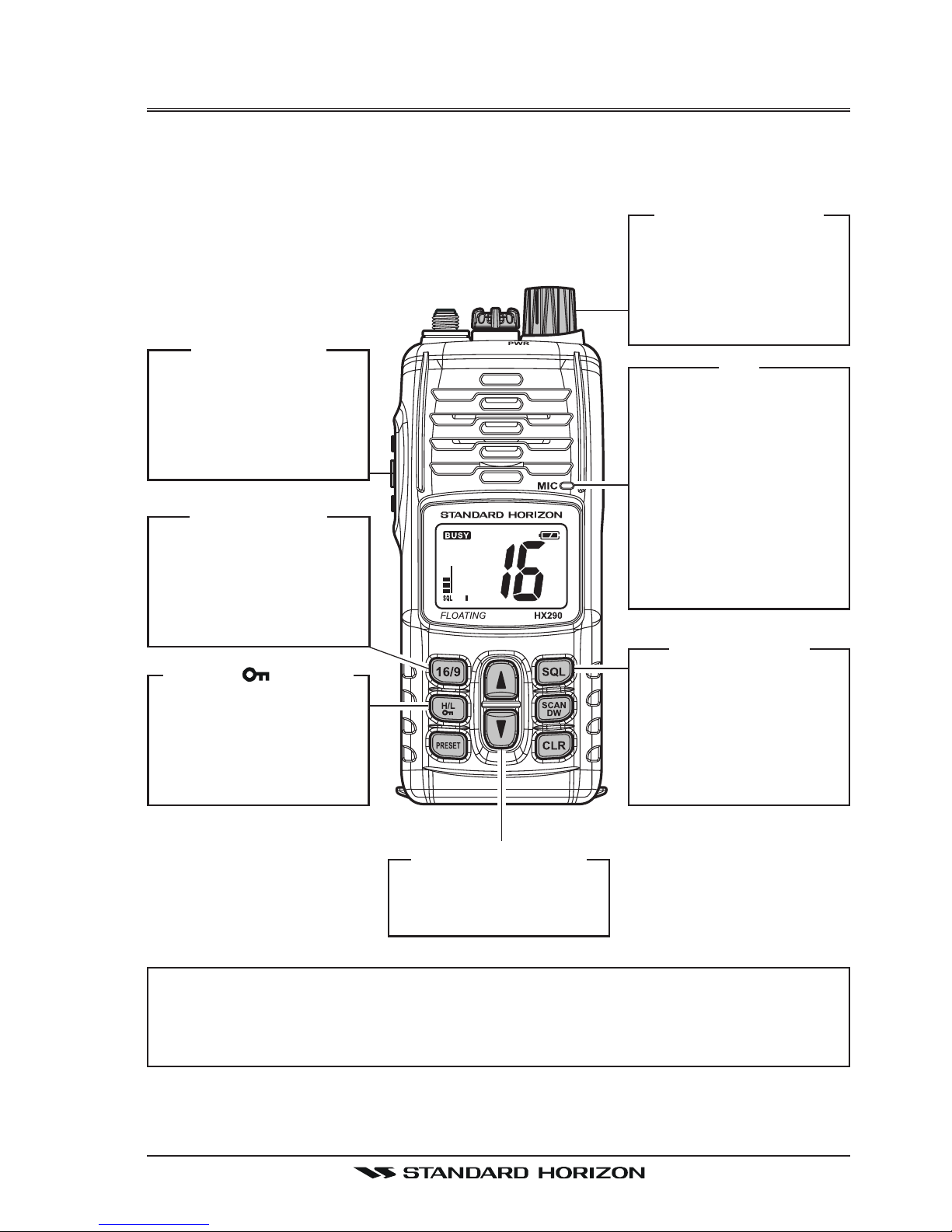
QUICK REFERENCE GUIDE
This transceiver is equipped with the E2O (Easy-To-Operate) system. You can
do the basic operation in numerical order of the illustration below.
[
PWR/VOL
]
K
NOB
Rotate this knob
clockwise to turn on
the radio, and adjust
the audio level.
[
SQL
]
B
UTTON
Press this key first,
then press the [
]
key to squelch or
press the [
]
key to
un-squelch the radio.
[]/[]
B
UTTONS
Selects the operating
channel.
MIC
When transmitting,
position your mouth
about 2 cm away
from the small mic
hole.
Speak slowly and
clearly into the microphone.
[
16/9
]
B
UTTON
Press to recall
channel 16.
Press and hold to
recall channel 9.
[
H/L
( )]
B
UTTON
Press to toggle the
transmit power between High (5W) and
Low (1W).
[
PTT
]
S
WITCH
Speak into the microphone in a normal
voice level while
pressing this switch.
NOTE
For additional details, refer to the section “5. CONTROLS AND INDICATORS”.
HX290EPage 4
1. GENERAL INFORMATION
1.1 INTRODUCTION
Congratulations on your purchase of the HX290E! The HX290E is a JIS-8/
IPX8 Submersible Floating 5-Watt portable two way marine transceiver. The
transceiver has all allocated International, Canadian, or US channels. It has
emergency channel 16 which can be immediately selected from any channel
by pressing the key.
The HX290E includes the following features: 10 Programmable Preset Chan-
nels, Memory, Priority, Dual Watch Scanning, easy-to-read large LCD display,
EEPROM memory back-up, Battery Life displayed on LCD, Glow-In-The-Dark
strip, and a transmit Time-Out Timer (TOT).
The HX290E transmitter provides a full 5 Watt of transmit power and also is
selectable to 1 Watt to assist the user in ensuring maximum battery life.
JIS-8/IPX8: 1.5 m for 30 minutes
1.2 RF EXPOSURE SAFETY STATEMENT
Your wireless handheld portable transceiver contains a low power transmitter.
When the Push-to-Talk (PTT: ) button is pushed, the transceiver sends out
radio frequency (RF) signals.
This device is authorized to operate at a maximum duty factor not to exceed
2:1 (this corresponds to 50% transmission time and 50% reception time), but
normal usage should not exceed 3:1 (25% transmission time and 75% reception/standby time).
This transmitter and its antenna must maintain a separation distance of at
least 2 cm from your face. Speak in a normal voice, with the antenna pointed
up and away from the face at the required separation distance.
Use only the supplied antenna. Unauthorized antennas, modifications, or attachments could damage the transmitter.
This transceiver works on frequencies which are not generally permitted.
For frequency allocation, apply for a licence at your local spectrum management authority. For actual usage contact your dealer or sales
shop in order to get your transceiver adjusted to the allocated
frequency range.
Attention in case of use
AUT BEL BGR CYP CZE DEU DNK
ESP EST FIN FRA GBR GRC HUN
IRL ITA LTU LUX LVA MLT NLD
POL PRT ROM SVK SVN SWE CHE
ISL LIE NOR
List of the practicable area
Page 5HX290E
2. ACCESSORIES
2.1 PACKING LIST
When the package containing the transceiver is first opened, please check it
for the following contents:
HX290E Transceiver
CAT460 Antenna
FNB-110LI 7.4 V, 1170 mAh Li-Ion Battery Pack
CD-52 Charger Cradle for HX290E
PA-48C/U 230VAC Wall Charger for CD-52
CLIP-22 Belt Clip
Hand Strap
Owner’s Manual
Warranty Card
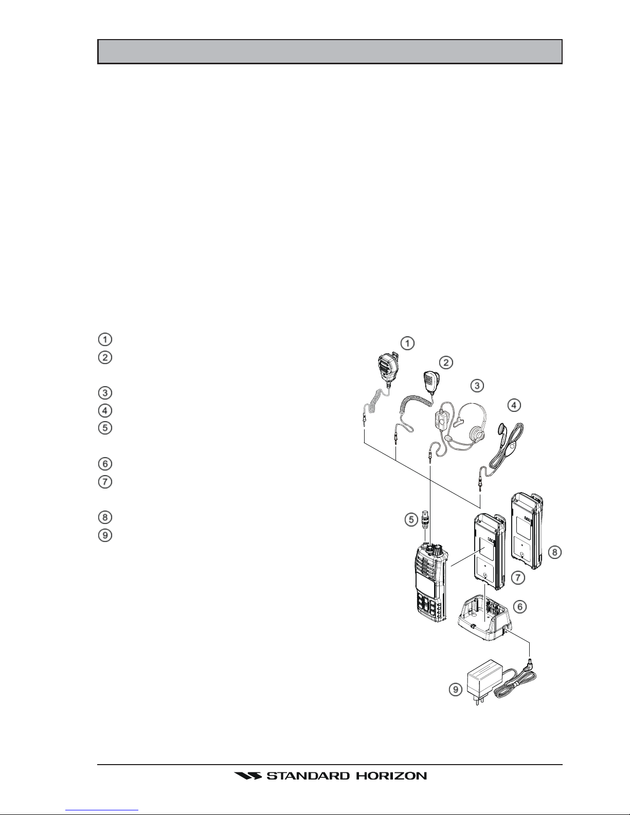
2.2 OPTIONS
MH-73A4B Speaker/Microphone
MH-57A4B Mini Speaker/Micro-
phone
VC-24 VOX Headset
VC-27 Earpiece/Microphone
CN-3 Radio-to-Ship’s Antenna
Adapter
CD-52 Charger Cradle
FNB-110LI 7.4 V, 1170 mAh Li-Ion
Battery Pack
FBA-42 Alkaline Battery Case
PA-48B/C/U
AC Wall Charger for the
CD-52
:
“B” suffix is for use with 120 VAC (Type-
A plug), “C” suffix is for use with 230 VAC
(Type-C plug), and “U” suffix is for use
with 230 VAC (Type-BF plug).
Note: Before operating the HX290E for the
first time, it is recommended that the bat-
tery be charged. Please see section “4.3.3
BATTERY CHARGING” for details.

HX290EPage 6
3. ABOUT THIS RADIO
3.1 ABOUT THE VHF MARINE BAND
The radio frequencies used in the VHF marine band lie between 156 and 158
MHz. The marine VHF band provides communications over distances that are
essentially “Line of sight” Actual transmission range depends much more on
antenna type, gain and height than on the power output of the transmitter. On
a fixed mount 25 W radio transmission expected distances can be greater
than 24 km, for a portable 5 W radio transmission the expected distance can
be greater than 8 km in “Line of sight”.
The use of Marine VHF radio is governed by regulation and local laws. Use by
unauthorized persons is not permitted and is subject to fines and confiscation
if convicted. This is especially true when the radio is used on land in a non
marine environment where because of location or propagation anomalies especially during the summer, the transmission may cause interference with a
search and rescue operation or contribute to a marine collision between passing ships. For VHF marine channel assignments refer to Page 33 Section 10.
3.2 ABOUT WATER RESIST ANCE
Water resistance of the transceiver is ensured only when the battery pack is
attached to the transceiver and MIC/SP cap is installed in the MIC/SP jack.
3.3 DISTRESS AND HAILLING (CHANNEL 16
)
Channel 16 is known as the Distress and Calling Channel. An emergency may
be defined as a threat to life or property. In such instances, be sure the transceiver is on and set to “Channel 16”. Then use the following procedure:
1. Press the PTT
(
Push-To-Talk:
)
switch and say “Mayday, Mayday, May-
day. This is _____, _____, _____” (your vessel’s name).
2. Then repeat once: “Mayday, _____” (your vessel’s name).
3. Now report your position in latitude/longitude, or by giving a true or magnetic bearing (state which) to a well-known landmark such as a navigation
aid or geographic feature such as an island or harbour entry.
4. Explain the nature of your distress (sinking, collision, aground, fire, heart
attack, life-threatening injury, etc.).
5. State the kind of assistance your desire (pumps, medical aid, etc.).
6. Report the number of persons aboard and condition of any injured.
7. Estimate the present seaworthiness and condition of your vessel.
8. Give your vessel’s description: length, design (power or sail), color and other
distinguishing marks. The total transmission should not exceed 1 minute.
9. End the message by saying “OVER”. Release the PTT
( )
switch and
listen.

Page 7HX290E
10. If there is no answer, repeat the above procedure. If there is still no response, try another channel.
3.4 CALLING ANOTHER VESSEL (CHANNEL 16 OR 9
)
Channel 16 may be used for initial contact (cailing) with another vessel.
However, its most important use is for emergency messages. This channel
must be monitored at all times except when actually using another channel.
It is monitored by European Coast Guards and by other vessels. Use of channel 16 for cailing must be limited to initial contact only. Calling should not exceed 30 seconds, but may be repeated 3 times at 2-minute intervals. In US
waters channel 9 may be used as an alternative calling channel for non-emergency communications. When cailing on channel 9, the calling time should not
exceed 30 seconds but may be repeated 3 times at 2-minute intervals.
Prior to making contact with another vessel, refer to the channel charts in this
manual, and select an appropriate channel for communications after initial
contact. For example, Channels 68 and 69 of the UK VHF Charts are some of
the channels available to non-commercial (recreational) boaters. Monitor your
desired channel in advance to make sure you will not be interrupting other
traffic, and then go back to either channel 16 or 9 for your initial contact.
When the cailing channel (16) is clear, state the name of the other vessel you
wish to call and then “this is” followed by the name of your vessel and your
Station License (Call Sign). When the other vessel returns your call, immedi-
ately request another channel by saying “go to”, the number of the other channel, and “over”. Then switch to the new channel. When the new channel is not
busy, call the other vessel.
After a transmission, say “over”, and release the PTT
(
Push-To-Talk:
)
switch.
When all communication with the other vessel is completed, end the last trans-
mission by stating your Call Sign and the word “out”. Note that it is not neces-
sary to state your Call Sign with each transmission, only at the beginning and
end of the contact.
Remember to return to Channel 16 when not using another channel.
HX290EPage 8
3.5 OPERATING ON CHANNEL 13
Channel 13 is used at docks, bridges and for maneuvering in port. Messages
on this channel must concern navigation only, such as meeting and passing in
restricted waters. In emergencies and when approaching blind river bends,
High power is allowed. Pressing the key will change the power output from
Low Power (1 Watt) to High (5 Watts). When you change from this channel
then return to it, low power will be automatically selected.
3.6 OPERATING ON CHANNEL 67
When channel 67 is used for navigational bridge-to-bridge traffic between ships,
High power may be used temporarily (in the USA band) by pressing the
key. When the PTT
( )
switch is released, the transceiver will revert to low
power.
3.7 SIMPLEX/DUPLEX CHANNEL USE
Refer to the section “9. VHF MARINE CHANNEL ASSIGNMENT” for instruc-
tions on use of simplex and duplex channels.
NOTE
All channels are factory-programmed in accordance with FCC, Industry
Canada, and International regulations. The mode of operation cannot
be altered from simplex to duplex or vice-versa. Simplex (ship to ship)
or duplex (marine operator) mode is automatically activated, depending
on the channel and whether the International, USA, or Canadian operating band is selected.
IMPORTANT NOTICE
Please follow these cautions to prevent hearing damage:
Always adjust the audio level of the transceiver to the minimum be-
fore connecting the VC-24 VOX Headset or VC-27 Earpiece/Micro-
phone to the transceiver.
Use the VC-24 VOX Headset and VC-27 Earpiece/Microphone at as
low a volume as possible for existing conditions.
Slowly adjust the VOL knob when increasing the audio level.

Page 9HX290E
MEMO
HX290EPage 10
4. GETTING STARTED
4.1 RADIO CARE
CAUTION
Before following the instructions below, insure the battery pack is in place
and firmly connected. Care must be taken if the radio was dropped and
a close inspection may be needed to insure the radio case and gaskets
are in adequate condition.
The design of the HX290E allows water to enter between the radio and the
battery pack, however waterproof performance is not compromised.
After using the HX290E in salt water environment is recommended to clean
the radio with fresh water by rinsing the battery and radio (separately) under a
sink facet or by dunking in a fresh water. After washing, use a soft cloth to
thoroughly dry all parts of the radio and battery.
This will keep the radio parts and the battery clean and in top operating condition.
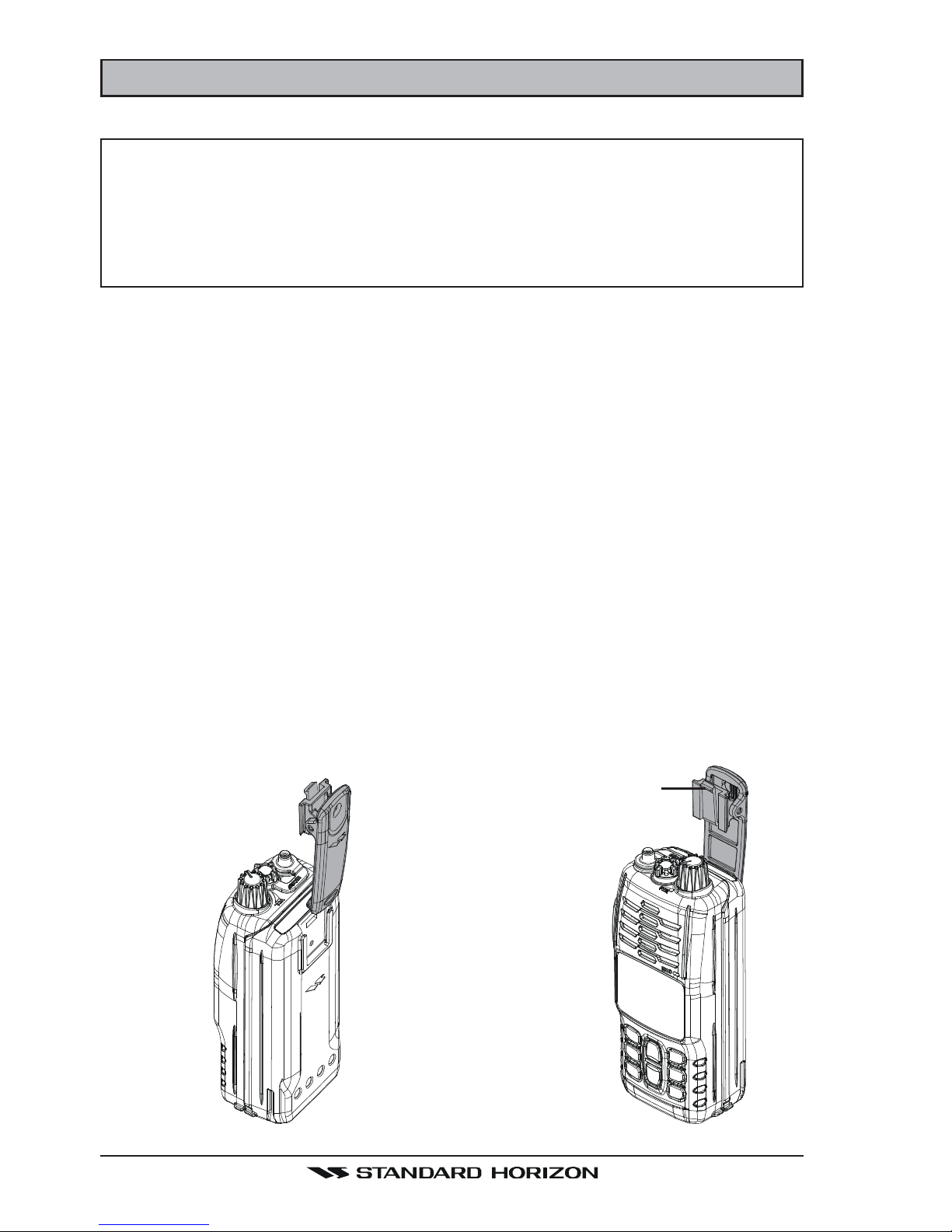
4.2 BELT CLIP INSTALLATION AND REMOVAL
To install the Belt Clip: align the
Belt Clip to the groove of the Battery pack, then press the Belt Clip
downward until it locks in place
with a “Click.”
To remove the Belt Clip: press the
Belt Clip Tab away from the battery pack to unlock the Belt Clip,
then slide the Belt Clip upward to
remove it.
Belt Clip Tab

Page 11HX290E
4.3 BATTERIES AND CHARGERS
If the radio has never been used, or its charge is depleted, it may be charged
by connecting the CD-52 Charger Cradle with the PA-48C/U battery charger.
Refer to the section “4.3.3 BATTERY CHARGING” for details. The PA-48C/U
will charge a completely discharged FNB-110LI battery pack in about 6 hours.
The FNB-110LI is a high performance Li-Ion battery providing high capacity in
a compact package.
CAUTION
To avoid risk of explosion and injury, FNB-110LI battery pack should
only be removed, charged or recharged in non-hazardous environments.
4.3.1 BATTERY SAFETY
Battery packs for your transceiver contain Li-Ion batteries. This type of battery
stores a charge powerful enough to be dangerous if misused or abused, especially when removed from the transceiver. Please observe the following precautions:
DO NOT SHORT BATTERY PACK TERMINALS: Shorting the terminals that
power the transceiver can cause sparks, severe overheating, burns, and battery cell damage. If the short is of sufficient duration, it is possible to melt
battery components. Do not place a loose battery pack on or near metal surfaces or objects such as paper clips, keys, tools, etc. When the battery pack is
installed on the transceiver, the terminals that transfer current to the transceiver are not exposed. The terminals that are exposed on the battery pack
when it is mounted on the transceiver are charging terminals only and do not
constitute a hazard.
DO NOT INCINERATE: Do not dispose of any battery in a fire or incinerator.
The heat of fire may cause battery cells to explode and/or release dangerous
gases.
Battery Maintenance
For safe and proper battery use, please observe the following:
Battery packs should be charged only in non-hazardous environments;
Use only STANDARD HORIZON-approved batteries;
Use only a STANDARD HORIZON approved charger. The use of any
other charger may cause permanent damage to the battery.
Follow charging instructions provided with the chargers.
Keep the battery contacts clean.
HX290EPage 12
Battery Storage
Store the batteries in a cool place to maximize storage life. Since batteries are
subject to self-discharge, avoid high storage temperatures that cause large
self-discharge rates. After extended storage, a full recharge is recommended.
Battery Recycling
DO NOT PLACE USED BATTERIES IN YOUR REGULAR TRASH!
LI-ION BATTERIES MUST BE COLLECTED, RECYCLED OR DISPOSED
OF IN AN ENVIRONMENTALLY SOUND MANNER.
The incineration, land filling or mixing of Li-Ion batteries with the municipal
solid waste stream is PROHIBITED BY LAW in most areas.
Return batteries to an approved Li-Ion battery recycler. This may be where
you purchased the battery.
Contact your local waste management officials for other information regarding
the environmentally sound collection, recycling and disposal of Li-Ion batteries.
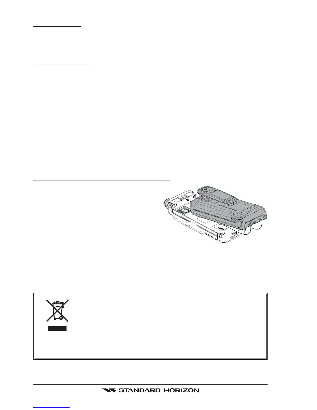
4.3.2 BATTERY INSTALLATION/REMOVAL
To install the battery pack, hold the
transceiver with your left hand, so your
palm is over the speaker and your
thumb is on the top of the belt clip. Insert the battery pack into the battery
compartment on the back of the radio
while tilting the Belt Clip outward, then
push the bottom side of the battery pack until the battery pack locks with
the Battery Pack Latch.
To remove the battery, turn the radio off. Slide the Battery Pack Latch on
the bottom of the radio, then lift up on the bottom of the battery and remove
it from the radio.
DO NOT PLACE USED BATTERIES IN YOUR NORMAL
BIN. LI-ION BATTERIES MUST BE COLLECTED, RECYCLED OR DISPOSED OF IN AN ENVIRONMENTALLY
SOUND MANNER.
Please contact your local council for information on disposing of
Li-on Batteries.
 Loading...