

Standard Horizon HX210, HX210E Owner's Manual
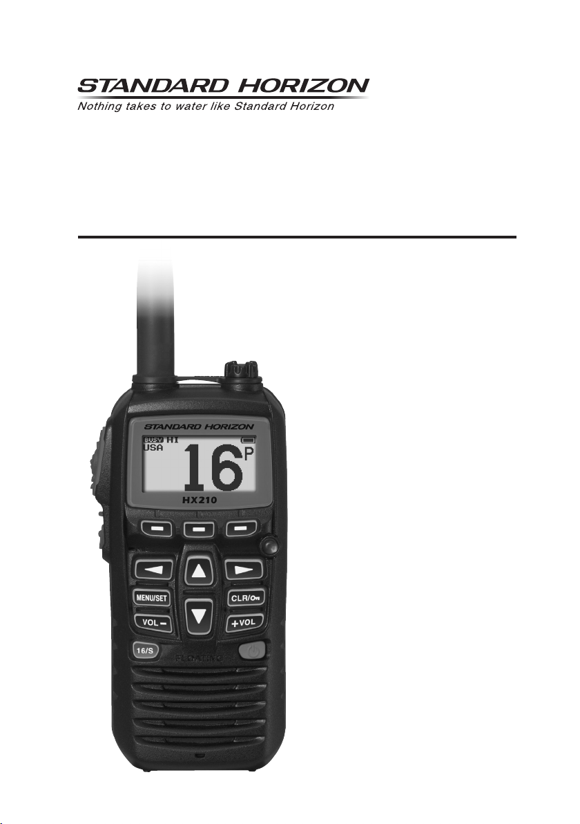
HX210
HX210E
Floating VHF FM Marine Transceiver
Owner’s Manual

TABLE OF CONTENTS
QUICK REFERENCE ............................................. 1
1. GENERAL INFORMATION .............................. 2
1.1 INTRODUCTION ........................................ 2
2. SAFETY PRECAUTIONS ................................ 3
3. ONLINE WARRANTY REGISTRATION .......... 4
4. ABOUT THIS RADIO ....................................... 4
4.1 ABOUT THE VHF MARINE BAND ............. 4
4.2 ABOUT WATER PROTECTION ................. 4
4.3
DISTRESS AND HAILING (CHANNEL 16
4.4 CALLING ANOTHER VESSEL
(CHANNEL 16 OR 9
4.5 BRIDGE CHANNELS 13 AND 67 .............. 6
4.6 SIMPLEX/DUPLEX CHANNEL USE .......... 6
4.7
AUTOMATED RADIO CHECK SERVICE
(in the USA only
4.8 NOTES TO ASSURE WATERPROOF
INTEGRITY ... 7
4.9 RADIO CARE ............................................. 7
5. ACCESSORIES ................................................ 8
5.1 PACKING LIST ........................................... 8
5.2 OPTIONS ................................................... 8
6. GETTING STARTED ........................................ 9
6.1 BATTERIES AND CHARGERS .................. 9
6.1.1 BATTERY SAFETY ............................. 9
6.1.2 BATTERY CHARGING ...................... 10
6.1.3 BATTERY LIFE INFORMATION ........ 11
6.2
BELT CLIP INSTALLATION / REMOVAL
7. CONTROLS AND INDICATORS .................... 12
7.1 CONTROLS AND SWITCHES ................. 12
7.2 LCD INDICATORS ................................... 14
8. BASIC OPERATION ...................................... 16
8.1 PROHIBITED COMMUNICATIONS ......... 16
8.2 INITIAL SETUP ........................................ 16
8.3 RECEPTION ............................................ 16
8.4 TRANSMISSION ...................................... 16
8.4.1 TRANSMIT POWER .......................... 17
8.4.2
TRANSMIT TIME - OUT TIMER (TOT
8.5 CHANNEL GROUP .................................. 17
8.6 KEYPAD LOCKING .................................. 18
8.7 NOAA WEATHER CHANNELS
(In USA and Canada only
8.7.1 NOAA WEATHER ALERT .................. 18
8.7.2 NOAA WEATHER ALERT TESTING . 19
8.8
PRESET CHANNELS: INSTANT ACCESS
8.8.1 PROGRAMMING PRESET
CHANNEL BANKS .... 19
8.8.2 OPERATION on a Preset Channel .... 20
8.8.3 Deleting a Preset Channel ................. 20
8.9 SCANNING .............................................. 21
8.9.1 PROGRAMMING SCAN MEMORY ... 21
8.9.2 SELECTING SCAN TYPE ................. 21
8.9.3 SCANNING OPERATION .................. 22
8.10
MULTI WATCH (TO PRIORITY CHANNEL)
8.10.1
Setting up the Multi Watch Operation
8.10.2 Starting the Dual Watch ..................... 23
8.10.3 Starting the Triple Watch ................... 24
8.11 Listening to the FM Broadcast Radio ....... 24
8.11.1 FM broadcast Frequency
sweep operation ....... 25
8.11.2 Store the FM frequency ..................... 25
8.11.3 Memory Frequency Recall ................. 25
8.12 Soft Keys .................................................. 26
8.12.1 Key Assignment ................................. 26
8.12.2 Key Timer .......................................... 26
... 4
)
) ... 5
) ... 6
... 11
... 17
)
) ... 18
... 19
... 23
... 23
9. MENU (“SETUP”) ......................................... 27
9.1 CHANNEL SETUP ................................... 27
9.1.1 CHANNEL GROUP ........................... 27
9.1.2 WEATHER ALERT
(in USA and Canada only) .......... 27
9.1.3 SCAN MEMORY ................................ 27
9.1.4 SCAN TYPE ...................................... 27
9.1.5 SCAN RESUME ................................ 28
9.1.6 MULTI WATCH .................................. 28
9.1.7 PRIORITY CH ................................... 28
9.1.8 SUB CH ............................................. 28
9.2 FM SETUP ............................................... 29
9.2.1 ADD ................................................... 29
9.2.2 EDIT .................................................. 30
9.2.3 DELETE ............................................. 30
9.3 CONFIG ................................................... 30
9.3.1 KEY BEEP ......................................... 30
9.3.2 BATTERY SAVE ................................ 31
9.3.3 STROBE LED .................................... 31
9.3.4 KEY SETUP ....................................... 32
9.3.5 BACKLIT LEVEL ................................ 32
9.3.6 BACKLIT TIMER ................................ 33
9.3.7 CONTRAST ....................................... 33
9.3.8 RESET ............................................... 33
9.4 ABOUT... .................................................. 34
10. ATIS SETUP (HX210E only) .......................... 35
10.1 ATIS CODE PROGRAMMING ................. 35
10.2 ATIS CH GROUP ..................................... 36
11. MAINTENANCE ............................................. 37
11.1 GENERAL ................................................ 37
11.2 FACTORY SERVICE ................................ 37
11.3 TROUBLESHOOTING CHART ................ 37
12. VHF MARINE CHANNEL ASSIGNMENTS .... 38
12.1 HX210 (USA Version
12.2 HX210E .................................................... 41
13. SPECIFICATIONS .......................................... 43
14. FCC AND CANADA RADIO LICENSE
INFORMATION .... 44
14.1 MARITIME STATION LICENSE ............... 44
14.2 MARINE RADIO CALL SIGN ................... 44
14.3
CANADIAN SHIP STATION LICENSING
14.4 FCC / ISED INFORMATION ..................... 44
15. RF EXPOSURE SAFETY STATEMENT ........ 45
15.1 SAFETY INFORMATION ......................... 45
15.2 CONSIGNES DE SECURITE ................... 45
16. FCC NOTICE .................................................. 46
STANDARD HORIZON Limited Warranty .......... 48
) ............................... 38
... 44
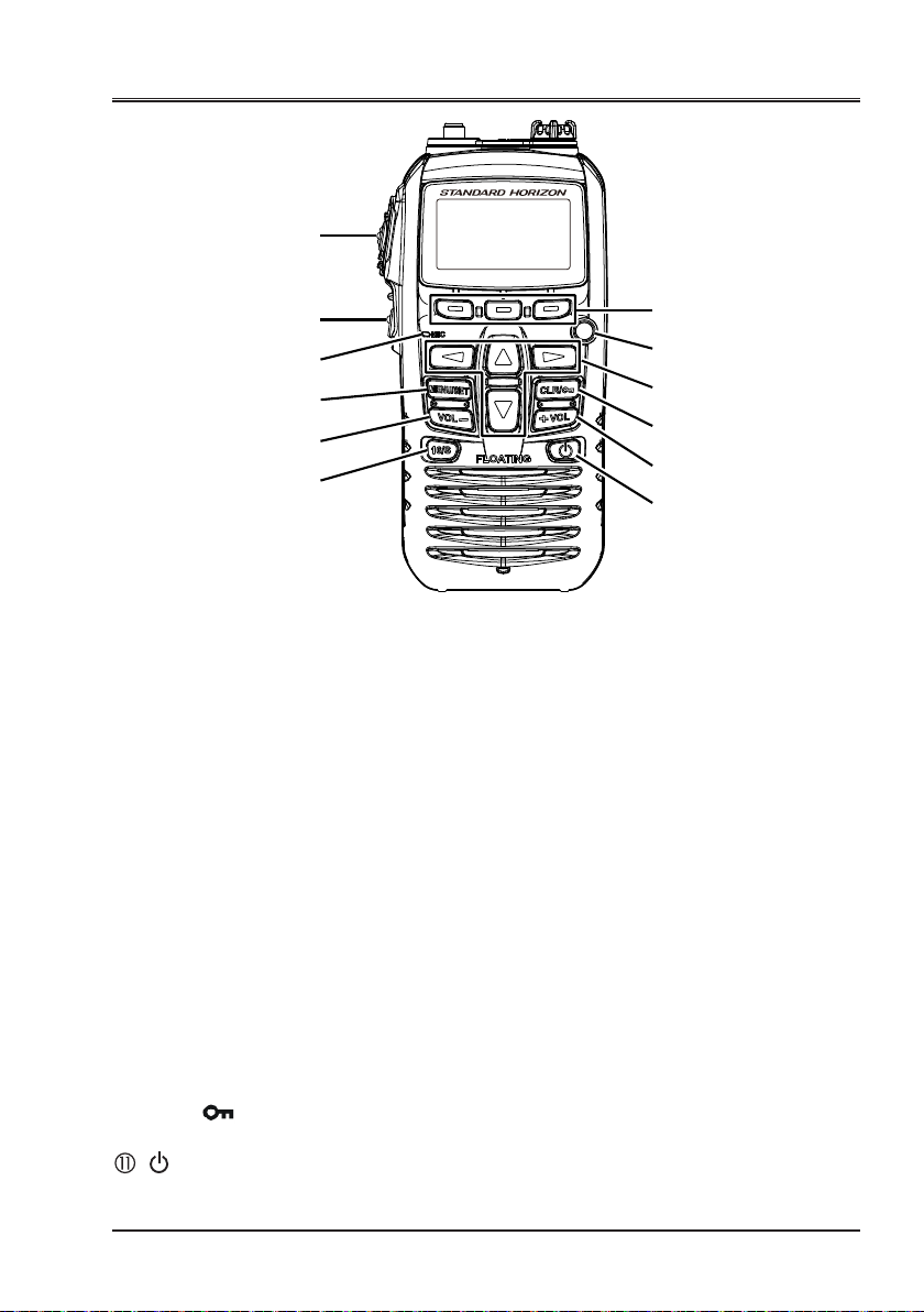
QUICK REFERENCE
①
②
③
④
⑤
⑥
⑧
⑨
⑩
⑪
⑦
⑤
HX210
PTT (Push-To-Talk): Activates the transmitter when pressed.
SQL: Press to display the SQL level setting screen, then press the [▲]
key to squelch or press the [▼] to un-squelch the radio.
MIC: Speak slowly and clearly into the MIC
1 inch (1.2 to 2.5 cm) away from your mouth while pressing the PTT key.
MENU/SET:
VOL− / VOL+: Press to adjust the speaker audio volume.
16/S:
Soft keys: These three programmable keys can be customized through
Strobe Light: Glows the Strobe Light continuously by pressing the
◄/►: Press to toggle the on-screen menus to right/left.
▼/▲: Press to change the operating channel.
CLR/ : Press to cancel a function or menu selection. Press and hold
: Press and hold to turn the transceiver ON/OFF.
Press to recall channel 16. Press and hold to recall the sub channel.
the setup menu mode. By pressing one of these keys briey, display the
key functions at the bottom of the display.
[STROBE] soft key.
to lock and unlock the keypad.
Press to access MENU. Press and hold to enter SETUP Mode.
aperture
having it about 1/2 to
Page 1

1. GENERAL INFORMATION
1.1 INTRODUCTION
Congratulations on your purchase of the HX210! Whether this is your
first por table marine VHF transceiver, or if you have other STANDARD
HORIZON equipment, the STANDARD HORIZON organization is committed to ensuring your enjoyment of this high-performance transceiver, which
should provide you with many years of satisfying communications even in
the harshest of environments. STANDARD HORIZON technical support
personnel stand behind every product sold, and we invite you to contact us
should you require technical advice or assistance. We appreciate your purchase of the HX 210, and encourage you to read this manual thoroughly, so
as to learn and fully understand the capabilities of the HX210.
1
*
The HX210 is a Submersible
Floating 6-Watt (5-Watt)
marine transceiver. The transceiver has all allocated International, USA, or
Canadian channels. It has emergency channel 16 which can be immediately
selected from any channel by pressing the [16/S] key.
The HX210 includes the following features: Memory Scanning, Priority
Scanning, Dual and Triple watch, NOAA Weather Alert, easy-to-read large
LCD display, Battery Life display on the LCD, and a transmit Time-Out Timer
(TOT).
The HX210 transmitter provides a full 6-Watt (5-Watt)* of transmit power
which is also to selectable to 1 Watt to assist the user in ensuring maximum
battery life.
2
*
portable two-way
The HX210E supports ATIS mode which is used in the inland waterways of
Europe. Please contact your local PTT administration or Marine Authority to
obtain your ATIS number.
We appreciate your purchase of the HX 210, and encourage you to read this
manual thoroughly, so as to learn and fully understand the capabilities of the
HX210.
1(IPX7 Specication for submersibility: 3 ft. (1 m) for 30 minutes)
*
*
2(5-Watt TX required in Some Countries)
Page 2
2. SAFETY PRECAUTIONS
Be sure to read the safety precautions, and use this product safely.
Yaesu is not liable for any failures or problems caused by the use or misuse of this product by the purchaser or any third party. Also, Yaesu is not liable for damages caused through the use of this product
by the purchaser or any third party, except in cases where ordered to pay damages under the laws.
Types and meanings of the marks
DANGER
WARNING
CAUTION
Types and meanings of symbols
These symbols signify prohibited actions, which must not be done to use this product safely.
For example: indicates that the product should not be disassembled.
These symbols signify required actions, which must be done to use this product safely. For example: indicates
that the power plug should be disconnected.
Do not operate the device when flammable gas is
generated.
Doing so may result in fire and explosion.
Do not transmit with this device in a crowded place
for the safety of persons using a medical device
such as a cardiac pacemaker.
The radio wave emitted from this product can cause the
medical device to malfunction and result in an accident.
Do not touch any liquid leaking from the liquid display with your bare hands.
There is a risk of chemical burns occurring when the
liquid comes into contact with the skin or gets into the
eyes. In this case, seek medical treatment immediately.
Do not power this transceiver with a voltage other
than the specified power supply voltage.
A fire, electric shock, or damage may result.
Do not make very long transmissions.
The main body of the transceiver may overheat, resulting component failure or operator burns.
Do not disassemble or make any alteration to this product.
An injury, electric shock, or failure may result.
Never touch the antenna during transmission.
This may result in injury, electric shock and equipment failure.
Do not place the transceiver on an unsteady or sloping surface, or in a location with extreme vibration.
The transceiver may fall or drop, resulting in fire, injury
and equipment damage.
Stay as far away from the antenna as possible during
transmission.
Long-term exposure to electromagnetic radiation may
have a negative effect on the human body.
Do not dangle or throw the transceiver by holding
its antenna.
This may injure others and may also result in damage
and failure of the transceiver.
Do not wipe the case using thinner and benzene etc.
Use only a soft, dry cloth to wipe stains from the case.
Keep this product out of the reach of children.
Injury to the child, or damage to the transceiver may result.
Do not use any products other than the specified
options and accessories.
Failure or miss operation may result.
This mark indicates an imminently hazardous situation, which, if not avoided, could result in death
or serious injury.
This mark indicates a potentially hazardous situation, which, if not avoided, could result in death
or serious injury.
This mark indicates a potentially hazardous situation, which, if not avoided, may result in minor or
moderate injury or only property damage.
DANGER
Do not touch any material leaking from the battery
pack with bare hands.
The chemical that has stuck to your skin or entered your
eye can cause chemical burns. In such a case, consult
the doctor immediately.
Do not solder or short-circuit the terminals of the
battery pack.
A fire, leak, overheating, explosion, or ignition may result.
Do not carry the battery pack together with a necklace,
hairpin, or small metal objects. A short circuit can result.
WARNING
Do not handle the battery pack or charger with wet
hands. Do not insert or remove the power plug with
wet hands.
An injury, leak, fire, or failure may result.
If smoke or a strange odor is emitted from the main
body, battery pack, or battery charger, immediately
turn the transceiver off; remove the battery pack.
A fire, chemical leak, overheating, component damage,
ignition, or failure may result. Please contact the dealer
from which you purchased this product.
CAUTION
If the transceiver will not be used for an extended
period, turn it OFF and remove the battery pack for
safety.
Do not throw the transceiver, or subject it to strong
impact forces.
Physical abuse may result in component damage and
equipment failure.
Keep magnetic cards and videotapes away from the
transceiver.
The data recorded on cash cards or videotapes may be
erased.
Do not use the transceiver in a crowded place.
The antenna may strike others and result in an injury.
Install the hand strap and belt clip securely.
Improper installation may cause the transceiver to fall or
drop, resulting in an injury or damage.
Before discarding a depleted battery pack, affix tape
or insulating covering to its terminals.
Page 3

3. ONLINE WARRANTY REGISTRATION
Please visit www.standardhorizon.com - Owner’s Corner to register the
HX210 Marine VHF.
NOTE:
ecial. When new products are released, information will appear on the website.
visiting the STANDARD HORIZON website from time to time may be ben-
4. ABOUT THIS RADIO
4.1 ABOUT THE VHF MARINE BAND
The radio frequencies used in the VHF marine band lie between 156 and
158 MHz with NOAA Weather stations available between 161 and 163 MHz.
The marine VHF band provides communications over distances that are
essentially “Line of sight” Actual transmission range depends much more
on antenna type, gain and height than on the power output of the transmit-
ter. On a xed mount 25 W radio transmission expected distances can be
greater than 15 miles, for a portable 5 W radio transmission the expected
distance can be greater than 5 miles in “Line of sight”.
The user of a Marine VHF radio is subject to severe nes if the radio is used
on land. The reasoning for this is you may be near an inland waterway, or
propagation anomalies may cause your transmission to be heard in a waterway. If this occurs, depending upon the marine VHF channel on which
you are transmitting, you could interfere with a search and rescue case, or
contribute to a collision between passing ships. For VHF Marine channel assignments refer to section “12. VHF MARINE CHANNEL ASSIGNMENTS”.
WARNING
This radio is capable of transmitting on Marine VHF radio frequencies.
The FCC allows the use of VHF Marine band on water areas only. Use of the
VHF Marine band when on land is not permitted. If persons use the VHF Marine
Band on land and interfere with other communications, the FCC will be notied
and search for the interference. Responsible parties found to be transmitting on
the VHF Marine Band on land could be ned up to $10,000 for the rst offense.
4.2 ABOUT WATER PROTECTION
The HX210 is only submersible* when the MIC/SP cap is installed in the
MIC/SP jack.
(
IPX7 Specication for submersibility: 3 ft. (1 m) for 30 minutes)
*
4.3 DISTRESS AND HAILING (CHANNEL 16
Channel 16 is designated as the Hail and Distress Channel. An emergency may
be dened as a threat to life or property. In such instances, be sure the transceiver is turned ON, and set to “Channel 16”. Then use the following procedure:
Page 4
)

1. Press the PTT (Push-To-Talk) switch and say “Mayday, Mayday, Mayday. This is _____, _____, _____” (your vessel’s name).
2. Then repeat once: “Mayday, _____” (your vessel’s name).
3. Now report your position in latitude/longitude, or by giving a true or magnetic bearing (state which) to a well-known landmark such as a navigation aid or geographic feature such as an island or harbor entry.
4. Explain the nature of your distress (sinking, collision, aground, re, heart
attack, life-threatening injury, etc.).
5. State the kind of assistance you desire (pumps, medical aid, etc.).
6. Report the number of persons aboard and condition of any injured.
7. Estimate the present seaworthiness and condition of your vessel.
8. Give your vessel’s description: length, design (power or sail), color and
other distinguishing marks. The total transmission should not exceed 1
minute.
9. End the message by saying “OVER”. Release the PTT switch and listen.
10. If there is no answer, repeat the above procedure. If there is still no response, try another channel.
4.4 CALLING ANOTHER VESSEL (CHANNEL 16 OR 9
Channel 16 may be used for initial contact (hailing) with another vessel.
However, its most important use is for emergency messages. This channel
must be monitored at all times except when actually using another channel.
It is monitored by the U.S. and Canadian Coast Guards and by other ves-
sels. Use of channel 16 for hailing must be limited to initial contact only. Calling should not exceed 30 seconds, but may be repeated 3 times at 2-minute
intervals. In areas of heavy radio trafc, congestion on channel 16 resulting
from its use as a hailing channel can be reduced signicantly in U.S. waters
by using Channel 9 as the initial contact (hailing) channel for non-emergency
communications. Here, also, calling time should not exceed 30 seconds but
may be repeated 3 times at 2-minute intervals.
Prior to making contact with another vessel, refer to the channel charts in this
manual, and select an appropriate channel for communications after initial
contact. For example, Channels 68 and 69 of the U.S. VHF Charts are some
of the channels available to non-commercial (recreational) boaters. Monitor
your desired channel in advance to make sure you will not be interrupting
other trafc, and then go back to either channel 16 or 9 for your initial contact.
When the hailing channel (16 or 9) is clear, state the name of the other vessel you wish to call and then “this is” followed by the name of your vessel
and your Station License (Call Sign). When the other vessel returns your
call, immediately request another channel by saying “go to”, the number of
the other channel, and “over ”. Then switch to the new channel. When the
new channel is not busy, call the other vessel.
)
Page 5

After a transmission, say “over”, and release the PTT (Push-To-Talk) switch.
When all communication with the other vessel is completed, end the last
transmission by stating your Call Sign and the word “out”. Note that it is not
necessary to state your Call Sign with each transmission, only at the beginning and end of the contact.
Remember to return to Channel 16 when not using another channel. Some
radios automatically monitor Channel 16 even when set to other channels or
when scanning.
4.5 BRIDGE CHANNELS 13 AND 67
Channel 13 is used at docks, bridges and by vessels maneuvering in port.
Messages on this channel must concern navigation only, such as meeting
and passing in restricted waters.
Channel 67 is used for navigational trafc between vessels.
By regulation, power is normally limited to 1 Watt on these channels. Your
radio is programmed to automatically reduce power to this limit on these
channels. However, in certain situations it may be necessary to temporarily
use a higher power. See page 14 for means to temporarily override the lowpower limit on these two channels.
4.6 SIMPLEX/DUPLEX CHANNEL USE
Refer to the section “12. VHF MARINE CHANNEL ASSIGNMENTS” for instructions on use of simplex and duplex channels.
NOTE
All channels are factory-programmed in accordance with FCC (USA),
ISED (Canada) and International regulations. The mode of operation
cannot be altered from simplex to duplex or vice-versa. Simplex (ship to
ship) or duplex (marine operator) mode is automatically activated, depending on the channel and whether the USA, International or Canadian
operating band is selected.
4.7 AUTOMATED RADIO CHECK SERVICE (in the USA only
In areas across the United States, Sea Tow offers boaters a way to conduct
radio checks. To use Sea Tow’s free Automated Radio Check service, simply
tune your VHF radio to the appropriate channel for your location and conduct
a radio check as you typically would. Upon releasing your radio’s microphone, the system will play an automated message and relay your transmission back to you, thereby letting you know how your signal will sound to
other boaters.
The Automated Radio Check Service is currently available in the areas listed below.
West Coast
Sea Tow Newport/LA - Ch. 27
Sea Tow San Diego - Ch. 27
Page 6
)

Northeast
Sea Tow Portland-Midcoast (Maine) - Ch. 27
Sea Tow Boston - Ch. 27
Sea Tow South Shore (Mass.) - Ch. 28
Sea Tow Rhode Island - Ch. 24
Sea Tow Eastern Long Island - Ch. 27
Sea Tow Huntington (N.Y.) - Ch. 27
Sea Tow Manasquan (N.J.) - Ch. 28
Mid-Atlantic
Sea Tow Northern Chesapeake (Md.) - Ch. 28
Sea Tow Central Chesapeake (Md.) - Ch. 27
Sea Tow Hampton Roads (Va.) - Ch. 28
North Carolina
Sea Tow Wrightsville Beach - Ch. 28
Sea Tow Ocean Isle Beach - Ch. 28
Florida
Sea Tow Sebastian - Ch. 28
Sea Tow Fort Lauderdale - Ch. 27
Sea Tow Charlotte Harbor - Ch. 24
Sea Tow Tampa Bay - Ch. 27
Sea Tow Horseshoe Beach - Ch. 27
Sea Tow Carrabelle/St. Marks - Ch. 27
Sea Tow Pensacola/Orange Beach (Ala.) - Ch. 27
4.8 NOTES TO ASSURE WATERPROOF INTEGRITY
CAUTION!
To ensure the waterproof integrity of the HX210, please make sure to observe the precautions described below of the HX210 observe the precau-
tions regarding waterproong as described below.
Failure to observe even one of the precautions may degrade the waterproof integrity, resulting in water intrusion into the transceiver. As a result,
the transceiver will not oat.
• To prevent water intrusion please make sure that the MIC/SP cap is
properly sealed.
Make sure that there is no dust, dirt or crack on the jack or the rubber gasket.
•
NOTE
If you nd any cracks on the MIC/SP cap or gasket, please contact Standard Horizon or your local dealer to purchase a replacement.
4.9 RADIO CARE
After using the HX210 in a salt water environment, it is recommended to
clean the radio with fresh water by rinsing the radio under a sink faucet or by
dunking the radio in a bucket of fresh water. After washing, use a soft cloth
and thoroughly dry all parts of the radio. This is to keep the rubber switches
and speaker grill clean and in top operating condition.
Page 7

5. ACCESSORIES
5.1 PACKING LIST
When the package containing the transceiver is rst opened, please check it
for the following contents:
HX210 Transceiver
CAT460 Antenna
2
SAD-23/SAD-11
*
AC Adapter for SBH-25
E-DC-19A DC Cable with 12 V Cigarette Lighter Plug
SBH-25 Charger Cradle
CLIP-22 Belt Clip
Hand Strap
Owner’s Manual
1
*
5.2 OPTIONS
2
SAD-23/SAD-11
SSM-14A
SEP-10A Earphone for SSM-14A
MH-73A4B Submersible Speaker / Microphone
SSM-64A VOX Headset
SSM-55A Earpiece / Microphone
CN-3 Radio-to-Ship’s-Antenna Adapter
SCH-11 Belt Clip Hanger
*
1(Antenna gain: -1.5dBi, Impedance: 50 ohm)
*
2(Depending on the transceiver version)
NOTE: Charge the battery before operating the HX210 for the first time.
Please see section “6.1 BATTERIES AND CHARGERS” for details.
*
AC Adapter for SBH-25
Submersible Speaker / Microphone with Earphone Jack
Page 8
6. GETTING STARTED
6.1 BATTERIES AND CHARGERS
If the radio has never been used, or its charge is depleted, it may be charged
by connecting the SBH-25 Charger Cradle with the SAD-23/SAD-11 AC
Adapter, see section “6.1.2 BATTERY CHARGING”. If 12V DC power is
available, the supplied E-DC-19A DC Cable with 12 V Cigarette Lighter Plug
may be used for charging the battery. The SAD-23/SAD-11 and E-DC-19A
will charge a completely discharged built-in battery in approximately 3 hours.
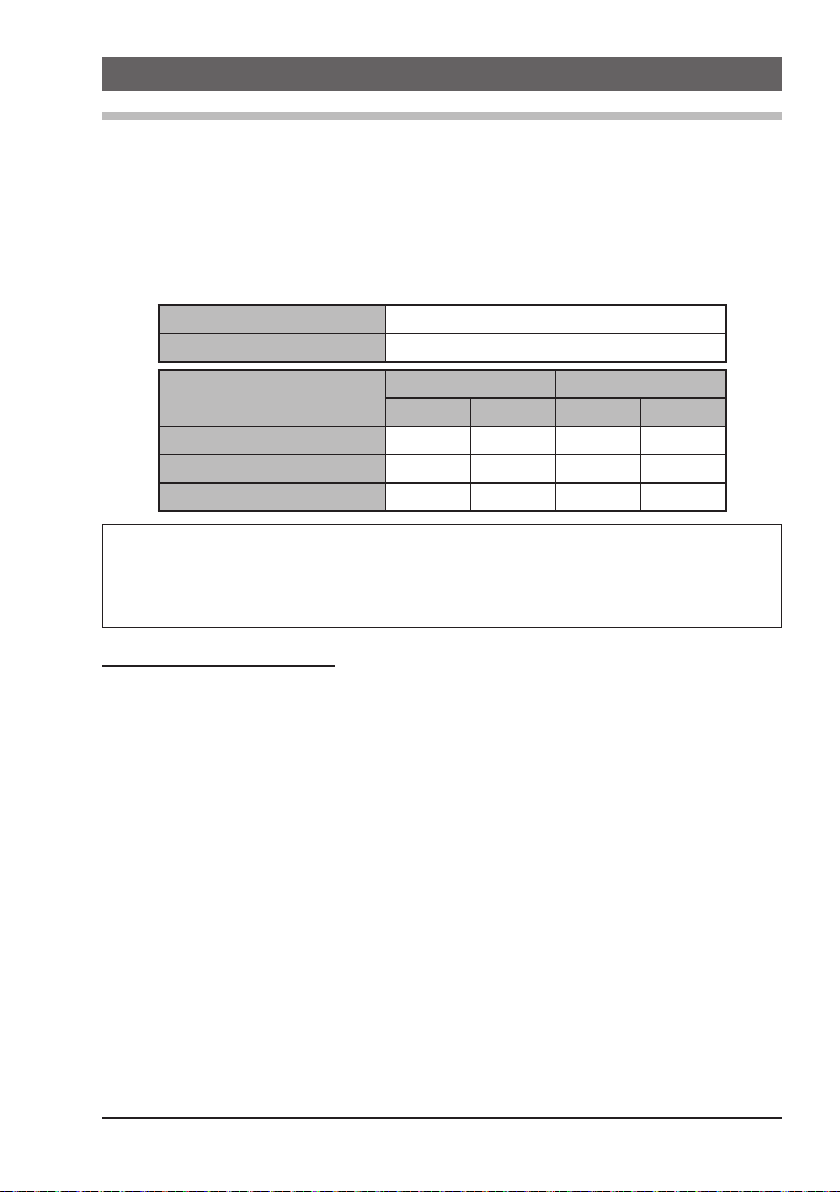
Built-in Rechargeable Battery
Capacity 1850 mAh
Nominal Voltage 7.4 V
Temperature Range
Charge 5 41 35 95
Discharge –20 –4 60 140
Storage –10 14 35 95
Minimum Maximum
°C °F °C °F
CAUTION
To avoid risk of explosion and injury, the built-in battery pack should only
be charged or recharged in non-hazardous environments.
6.1.1 BATTERY SAFETY
The built-in battery of this transceiver contains Li-ion batteries. This type
of battery stores a charge powerful enough to be dangerous if misused or
abused, especially when removed from the transceiver. Please observe the
following precautions:
DO NOT SHORT BATTERY PACK TERMINALS: Shorting the terminals
that power the transceiver can cause sparks, severe overheating, burns, and
battery cell damage. If the short is of sufcient duration, it is possible to melt
battery components. Do not place a loose battery pack on or near metal surfaces or objects such as paper clips, keys, tools, etc. When the battery pack
is installed on the transceiver, the terminals that transfer current to the transceiver are not exposed. The terminals that are exposed on the battery pack
when it is mounted on the transceiver are charging terminals only and do not
constitute a hazard.
DO NOT INCINERATE: Do not dispose of any battery in a re or incinerator.
The heat of re may cause battery cells to explode and/or release danger-
ous gases.
Page 9
Battery Maintenance
For safe and proper battery use, please observe the following:
Use only STANDARD HORIZON approved batteries.
Do not reverse the charge polarity. Use only the proper charger. If this is
tampered with or another charger is used, permanent damage may result.
Use only a STANDARD HORIZON approved charger. The use of any
other charger may cause permanent damage to the battery.
Battery Recycling
DO NOT PLACE USED BATTERIES IN THE REGULAR TRASH!
LI-ION BATTERIES MUST BE COLLECTED, RECYCLED
OR DISPOSED OF IN AN ENVIRONMENTALLY SOUND
MANNER.
Incinerating Li-ion batteries, placing them in the land ll, or mixing them with
the municipal solid waste collection, is PROHIBITED BY LAW in most areas.
Return batteries to an approved Li-ion battery recycler. This may be avail-
able you purchased the battery.
Contact your local waste management ofcials for other information regarding
the environmentally sound collection, recycling and disposal of Li-ion batteries.
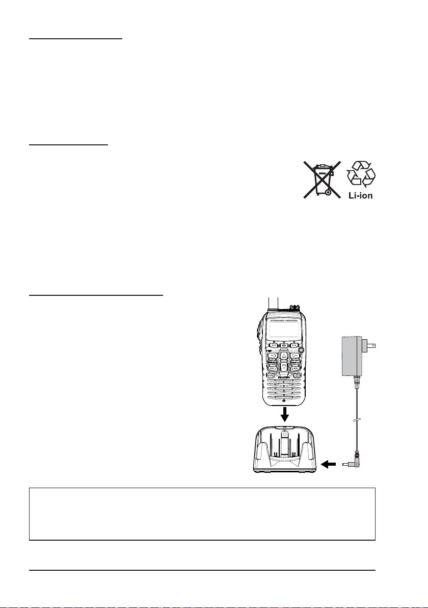
6.1.2 BATTERY CHARGING
Using the supplied battery charger and cradle,
it take about 3 hours* to charge the built-in battery fully.
*: Depending on the battery status, the charging
HX210
time might be increased.
1. Turn the transceiver OFF.
2. Referring to the gure at the right, connect
the battery charger plugs.
3. When the HX210 is inserted correctly, the
HX210’s LCD display will show the battery
charging icon.
4. When charging is completed, the battery
charging icon will disappear.
CAUTION
The SAD-23/SAD-11 and SBH-25 are NOT designed to be waterproof.
Do not attempt to charge in water hazardous locations.
Page 10
NOTE
The SAD-23/SAD-11 is only designed for the charging of the HX210’s
built-in battery, and is not suitable for other purposes. The SAD-23/
SAD-11 may introduce noise to TV and radio reception in the immedi-
ate vicinity, so it is not recommended for use adjacent to such devices.
Contact Standard Horizon dealer or Factory Service about the built-in
battery replacement. Refer to the section “11.2 FACTORY SERVICE”.
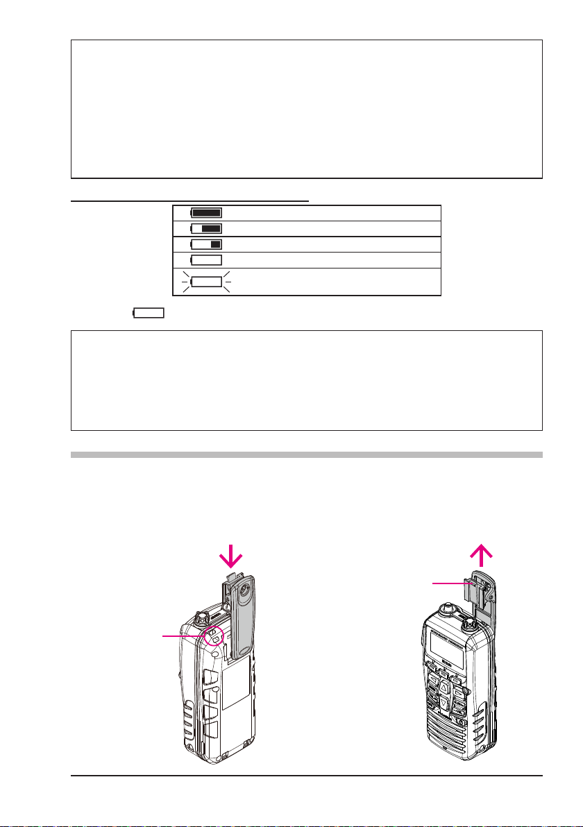
6.1.3 BATTERY LIFE INFORMATION
: Full battery power
: Enough battery power
: Low battery power
: Poor battery power. Charge battery.
: Charge the battery immediately
When the “ ” icon appears, it is recommended that the battery be charged soon.
WARNING
If the transceiver will be unused for a long period of time, be sure to
fully charge the built-in battery before storing it. When the transceiver
is stored for an extended period, recharge the built-in battery every six
months to prevent it from over-discharging.
6.2 BELT CLIP INSTALLATION / REMOVAL
r
To install the Belt Clip: align the
Belt Clip to the niche on the rear
of the transceiver, then slide the
Belt Clip downward until it locks
in place with a “Click”.
r
To remove the Belt Clip: press
the Belt Clip Tab away from the
rear of the transceiver to unlock
the Belt Clip, then slide the Belt
Clip upward to remove it.
Strap Hole
Belt Clip Tab
Page 11
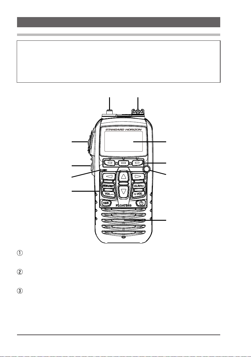
7. CONTROLS AND INDICATORS
7.1 CONTROLS AND SWITCHES
NOTE
This section denes each control of the transceiver. For detailed operating
instructions, refer to section “8. BASIC OPERATION”. Refer to the below
illustration for the locations of the following controls, switches, and connections.
HX210
ANT Jack (Top Panel
The supplied CAT460 exible antenna is attached here.
)
PTT (PUSH-TO-TALK) Switch (Left Side Panel
When pushed activates the transmitter.
SQL Switch
Press this key to SQL adjustment.
Secondary use:
Press and hold this key to open the squelch, allowing you to monitor the
operating channel. Press the key to resume normal (squelch controlled)
monitoring.
Page 12
)

Microphone
The internal microphone is located here.
When transmitting, position the microphone about 1/2 to 1 inch (1.2 ~ 2.5
cm) away from your mouth. Speak slowly and clearly into the microphone.
Keypad
(UP) Key
p
Press this key to change the operating channel or the squelch threshold level.
Pressing the key momentarily, will increase the channel (or level) will
increase one step. Holding the key, will increase the channel (or level)
continuously.
(DOWN) Key
q
Press this key to change the operating channel, or the squelch threshold level.
Pressing the key momentarily, will decrease the channel (or level) will
decrease one step. Holding the key, will decrease the channel (or level)
continuously.
& u Keys
t
Press these keys to toggle the on-screen menus right or left.
MENU/SET Key
Press to access MENU.
Secondary use:
Press and hold to enter SETUP Mode.
CLR/
Press to cancel a function or menu selection.
Secondary use:
Press and hold to lock and unlock the keypad.
VOL- & VOL+ Keys
Press these keys to enable the audio volume adjustment.
16/S Key
Pressing this key immediately recalls channel 16 from any channel se-
lection. Press and hold 16/S Key to recall the sub channel.
POWER Key
Press and hold this key to turn the radio “ON” or “OFF”.
MIC/SP Jack
The jack accepts the optional SSM-14A Speaker/Microphone, MH-
73A4B Submersible Speaker/Microphone, SSM-64A VOX Headset, or
SSM-55A Earpiece/Microphone. When this jack is used, the internal
speaker and microphone are disabled.
Key
Page 13
LCD Display
This display shows current operating conditions, as illustrated the below image.
Soft key
These three soft keys can be customized by the Setup Menu mode de-
scribed in section “8.12 Soft Keys”. When one of the soft keys is pressed
briey, the functions will appear above each key on the display.
Water Enabled Light
When the HX210 comes in contact with water, the light will blink white to
assist nding the radio in low light conditions. This feature operates when
the radio is ON or OFF.
Speaker
The internal speaker is located here.
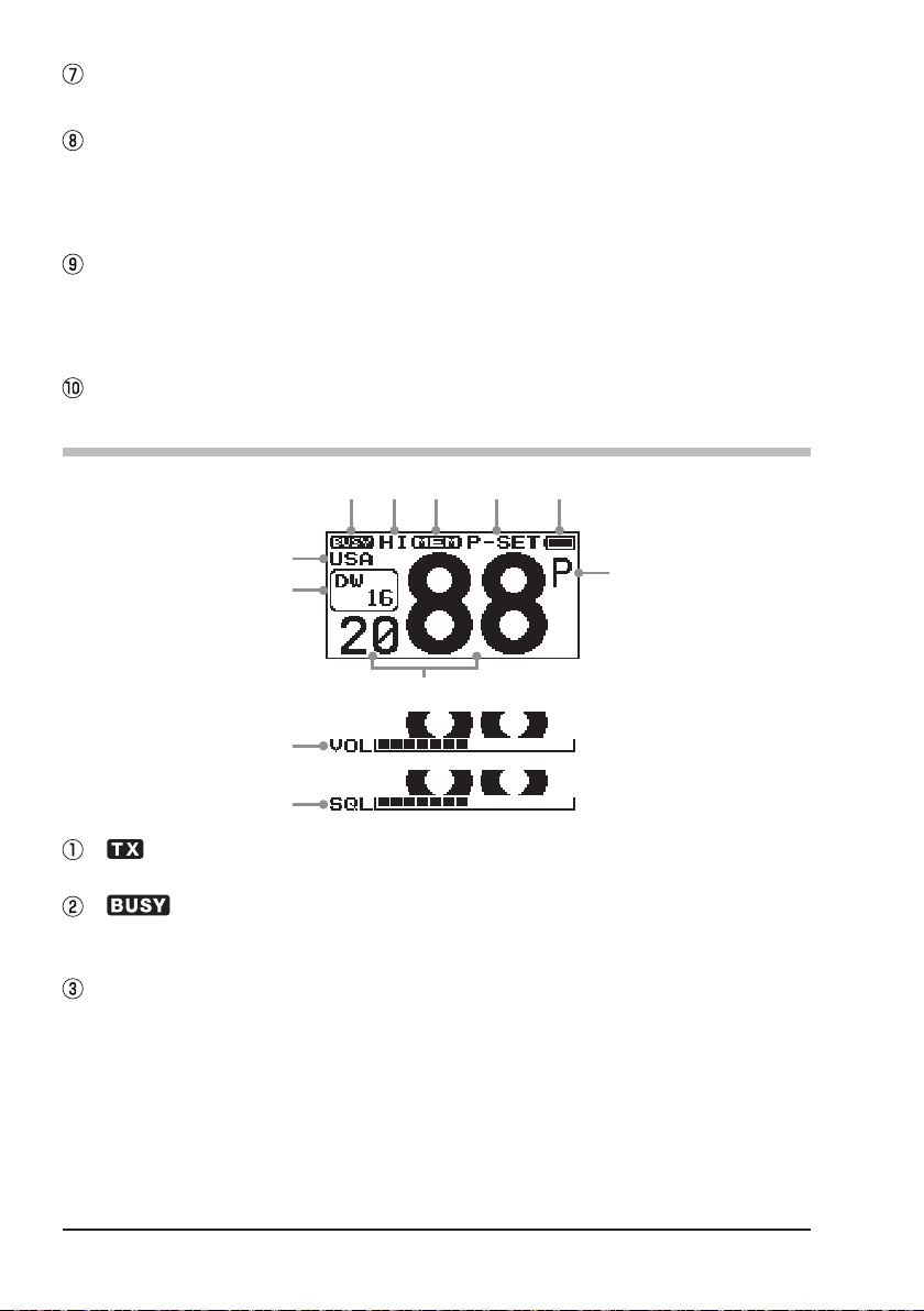
7.2 LCD INDICATORS
①② ⑥⑤ ⑦ ⑧
③
④
⑩
⑪
⑫
“ ” Indicator
This indicator appears during transmission.
“ ” Indicator
This indicator appears when a signal is being received or the radio is un-
squelched.
Channel Group Indicator
These indicators show the selected channel group.
“USA”: USA
“INTL”: International
“CAN”: Canada
“UK”: United Kingdom (U.K.)
“BE”: Belgium
“NL”: Netherlands
“SW”: Sweden
“GE”: German
⑨
Page 14
 Loading...