

Standard Horizon GX2350 Owner's Manual
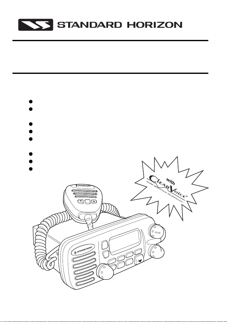
SPECTRUM GX2350S
25 Watt VHF/FM
Marine T ransceiver
Owner's Manual
Submersible
One-Button DSC Distress Call Automatically
Sends Latitude & Longitude and Vessel ID
Noise Canceling “Clear Voice” Speaker Microphone
20 W Loud Hailer with Bells & Whistles
Latitude & Longitude & Speed Over Ground & Course Over
Ground Shown On Display When Connected To GPS
Programmable Scan & Priority Ch16 Scan
NOAA Weather Alert
Backlit LCD & Keys
16/9
VOL/PWR
16/9
X
W
/B
A
A
C
S
SPECTRUM
Horizon
NAV
PA/FOG
S
S
E
R
T
SQL
IS
D
/L
H
PULL OPEN
CALL
/SET
MEM
N

TABLE OF CONTENTS
FCC NOTICE .......................................................................................................... 1
1 GENERAL INFORMATION.............................................................................. 2
INTRODUCTION .............................................................................................. 2
FCC/ INDUSTRY CANADA INFORMATION.................................................... 2
2 ACCESSORIES ............................................................................................... 3
PACKING LIST ................................................................................................. 3
OPTIONS ......................................................................................................... 3
3 CONTROLS AND INDICATORS ..................................................................... 4
CONTROLS AND CONNECTIONS ................................................................. 4
4 INSTALLATION ............................................................................................... 9
LOCATION ....................................................................................................... 9
ELECTRICAL CONNECTIONS ........................................................................ 9
ACCESSORY CABLE .................................................................................... 10
Cable pin number and signal ................................................................... 10
CMB16 FLUSH MOUNT INSTALLATION ...................................................... 11
5 BASIC OPERATION ...................................................................................... 12
RECEPTION................................................................................................... 12
TRANSMISSION ............................................................................................ 12
TRANSMIT TIME - OUT TIMER (TOT) .......................................................... 13
SIMPLEX/DUPLEX CHANNEL USE .............................................................. 13
USA, CANADA, AND INTERNATIONAL MODE ............................................ 13
NOAA WEATHER CHANNELS ...................................................................... 14
NOAA WEATHER ALERT .............................................................................. 14
MEMORY SCANNING ................................................................................... 15
CH16 PRIORITY SCANNING (PRI-SCAN) .................................................... 15
CHANNEL A /B INSTANT CALL .................................................................... 16
Storing new channel A/B .......................................................................... 16
Changing the stored channel A/B ............................................................ 16
Operating the channel A/B ...................................................................... 16
PA/FOG OPERATION .................................................................................... 16
Operating the PA HAIL mode................................................................... 17
Operating the FOG HORN mode ............................................................. 17
NAVIGATION INDICATION............................................................................ 18
VOICE SCRAMBLER ..................................................................................... 18
Operation with voice scrambler ................................................................ 18
RESETTING THE TRANSCEIVER’S MICROPROCESSOR ......................... 19
GX2350S Owner’s Manual page 48

6 DIGITAL SELECTIVE CALLING ................................................................... 20
GENERAL ...................................................................................................... 20
Digital Selective Calling (DSC)................................................................. 20
Marine Mobile Service Identity (MMSID).................................................. 20
SENDING A DISTRESS CALL ....................................................................... 21
SENDING A DISTRESS CALL WITH NATURE OF DISTRESS .................... 22
SENDING AN INDIVIDUAL CALL .................................................................. 23
SENDING AN ALL SHIP CALL ...................................................................... 24
SC STANDBY................................................................................................. 25
CALL WAITING DIRECTORY ........................................................................ 25
peration of Distress Call Waiting .............................................................. 26
Operation of Individual Call Waiting ......................................................... 26
POSITION REQUEST .................................................................................... 27
RECEIVING DSC CALLS ............................................................................... 28
Receiving a distress call........................................................................... 28
Receiving a distress relay call .................................................................. 29
Receiving an all ships call ........................................................................ 29
Receiving a geographical area call .......................................................... 29
Receiving an individual call ...................................................................... 29
Receiving a position request .................................................................... 30
7. DSC / RADIO SETUP MODE......................................................................... 31
SETUP............................................................................................................ 31
LAMP ADJUSTING ........................................................................................ 31
LCD CONTRAST............................................................................................ 31
INDIVIDUAL DIRECTORY SETUP (DSC) ..................................................... 32
POSITION REQUEST REPLY TYPE ............................................................. 33
VOICE SCRAMBLER ..................................................................................... 34
KEY BEEP (ON OR OFF) .............................................................................. 35
TIME OFFSET ................................................................................................ 36
USER MMSID INPUT ..................................................................................... 37
8 RAM MIC OPERATION.................................................................................. 38
RAM MIC CONTROLS AND CONNECTIONS ............................................... 38
INDICATORS ................................................................................................. 40
INTERCOM OPERATION .............................................................................. 41
Communication ........................................................................................ 41
Calling ...................................................................................................... 41
9 MAINTENANCE ............................................................................................. 42
REPLACEMENT PARTS................................................................................ 42
TROUBLESHOOTING CHART ...................................................................... 43
10 SPECIFICATIONS ......................................................................................... 44
GENERAL ...................................................................................................... 44
TRANSMITTER .............................................................................................. 44
RECEIVER ..................................................................................................... 44
page 49 Owner’s Manual GX2350S

FCC NOTICE
NOTICE
Unauthorized changes or modifications to this equipment may void
compliance with FCC Rules. Any change or modification must be
approved in writing by STANDARD HORIZON, a division of YAESU USA.
NOTICE
This equipment has been tested and found to comply with the limits for
a Class B digital device, pursuant to Part 15 of the FCC Rules. These
limits are designed to provide reasonable protection against harmful
interference in a residential installation. This equipment generates,
uses and can radiate radio frequency energy and, if not installed and
used in accordance with the instructions, may cause harmful
interference to radio communications. However, there is no guarantee
that interference will not occur in a particular installation. If this
equipment does cause harmful interference to radio or television
reception, which can be determined by turning the equipment off and
on, the user is encouraged to try to correct the interference by one or
more of the following measures:
— Reorient or relocate the receiving antenna.
— Increase the separation between the equipment and receiver.
— Connect the equipment into an outlet on a circuit different from
that to which the receiver is connected.
— Consult the dealer or an experienced radio/TV technician for
help.
page 1 Owner’s Manual GX2350S

1 GENERAL INFORMATION
1.1 INTRODUCTION
The STANDARD HORIZON (a division of YAESEU USA) GX2350S is a
VHF/FM transceiver designed for use in the frequency range of 156.025 to
163.275 MHz. The GX2350S requires 13.8V for operation and has a
switchable RF output power of 1 watt or 25 watts.
The transceiver is capable of RTCM SC101 DSC (Digital Selective Calling)
operation and intercom operation with the use of an optional CMP23
(remote-control speaker/microphone with display).
The transceiver operates on all currently-allocated marine channels which
are switchable for use with either USA, International, or Canadian
regulations. It has an emergency channel 16 which can be immediately
selected from any channel by pressing the red 16/9 key. NOAA Weather
channels can also be accessed immediately by pressing the WX key with
channel selection.
Other features of the transceiver include: scanning, priority scanning,
public address (PA) mode,submersible noise-canceling speaker mic, high
and low voltage warning, and GPS repeatability.
1.2 FCC/ INDUSTRY CANADA INFORMATION
The following data pertaining to the transceiver is necessary to fill out the
license application.
Type Acceptance ................................................................... FCC Part 80
Output Power .......................................... 1 Watt (low) and 25 Watts (high)
Emission.....................................................................16K0F3E, 16K0G3E
Frequency Range ............................................... 156.025 to 163.275 MHz
FCC Type Number ............................................................... K66GX2350S
Industry Canada Type Approval ............................................ 511822205A
Additional FCC and Industry Canada data, including licensing
requirements, are contained in the companion document titled
OWNER’S MANUAL SUPPLEMENT. The document also contains
charts for VHF channel assignments, transceiver procedures,
maintenance, factory service information, and warranty data.
GX2350S Owner’s Manual page 2

2 ACCESSORIES
2.1 PACKING LIST
When the package containing the transceiver is first opened, please check
it for the following contents:
• GX2350S SPECTRUM Transceiver (White/Black)
• CMP351W/CMP351B (White/Black Microphone attached to the
transceiver) and hanger kit
• Mounting Bracket and attaching hardware
• Spare Fuse (6 A, 250 V )
• Owner’s Manual
• Owner’s Manual Supplement
• Quick-Reference Card
• Accessory Cable
• Power Cord
2.2 OPTIONS
CMB16 ...................................................................... Flush-Mount Bracket
CMP23 ........................................ Remote-Access Microphone (RAM Mic)
CAW23............................................ 10-foot Extension Cable for RAM Mic
101S......................................................................Mini Extension Speaker
201S............................................................................. Extension Speaker
201SZ...................................................... Flush Mount Extension Speaker
CVS240............................................................................ Voice Scrambler
220SW ............................................................ 4.5" Round hailer/ PA Horn
230SW ................................................................... 5" X 8" Hailer/PA Horn
page 3 Owner’s Manual GX2350S

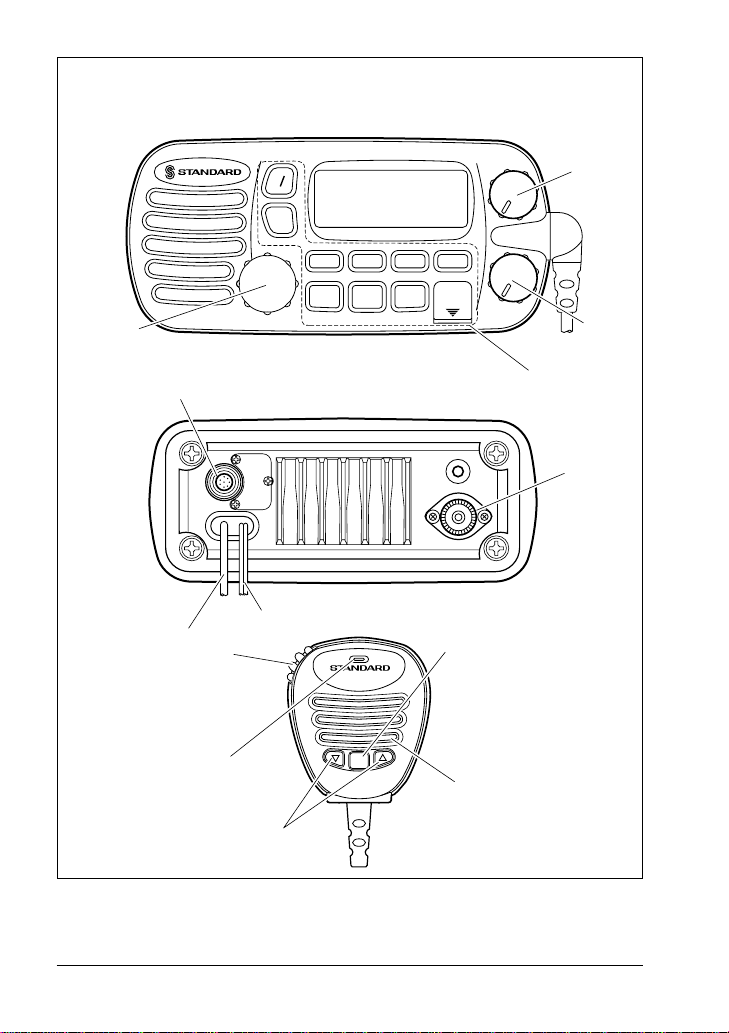
3 CONTROLS AND INDICATORS
NOTE
This section defines each control of the transceiver. See Figure 1 for
location of controls. For detailed operating instructions refer to chapter
4 of this manual.
3.1 CONTROLS AND CONNECTIONS
q POWER SWITCH/VOLUME CONTROL
Turns the transceiver on and off as well as adjusts the audio volume. To
turn the transceiver on press and hold this knob until the LCD turns on.
To turn it off, press and hold this knob until the LCD turns off. When the
power is turned on, the transceiver is set to the last selected channel.
Secondary Use
When the transceiver is turned on while the SCAN and WX keys are held
down, the internal microprocessor is reset. This clears the memory and all
user-programmed settings, such as scan memory,, priority scan
assignments, and A/B channel assignments. This condition is known as
the default condition, the same as when shipped from the factory. For a
list of these defaults, see the section on Resetting the Transceiver’s
Microprocessor.
NOTE
Resetting the microprocessor will not erase DSC MMSID and
Directory Call Waiting information.
w SQUELCH CONTROL (SQL)
Sets the point at which random noise on the channel does not activate
the audio circuits but a received signal does. This point is called the
squelch threshold. Further adjustment of the squelch control will
degrade reception of wanted transmissions.
e KEY PAD
16/9 Key
Immediately recalls channel 16 from any channel location. Holding
down this key recalls channel 9.
Secondary use
Please see secondary use for the WX and MEM key.
GX2350S Owner’s Manual page 4
r
PA VOL
16 9
w x
VOL / PWR
UIC
Horizon
SPECTRUM
A/B
SCAN
PA/FOG
H/L NAV
CALL
SET
MENU
DISTRESS
PULL OPEN
MEM
IC
SQL
q
w
t
u
y
o
!0
16/9
!1
Figure 1. Controls and Connectors
e
i
!2
!3
page 5 Owner’s Manual GX2350S

WX Key
Immediately recalls the previously selected NOAA weather channel
from any channel location.
Secondary use
1. Holding down the 16/9 key while pressing the WX key changes the
mode from USA to International or Canadian.
NOTE
If position is displayed, this icon will be hidden.
2. Holding down the WX and SCAN key while turning the power on resets
the microprocessor and erases scan channels from memory. This clears
the memory and establishes the factory-set defaults. For a list of these
defaults, see the section on Resetting the Transceiver’s Microprocessor.
SCAN Key
1. Starts and stops scanning of programmed channels.
2. If held while the UP or DOWN key on the mic case is pressed or channel
knob on radio is turned, the radio will show the channels in scan memory.
This function will not work if the unit is scanning.
NOTE
There is only one priority channel. However, it can be assigned to a
channel other than WX and CH70. The priority channel is marked with
P-CH on the LCD.
MEM Key
Memorizes the selected channel into the transceivers scan memory for
scanning. When pressed again it, DELETES the channel from the scan
memory.
Secondary use
The MEM key is also used to select a priority channel.
1. Select the desired channel.
2. Press and hold the MEM key until the display shows P-CH.
NOTE
If position is displayed, this icon will be hidden.
DISTRESS Key
To send the distress call see section 6.2, (Sending a Distress Call).
PA/FOG key
Available to operate the PA function or the FOGHORN function
GX2350S Owner’s Manual page 6

A/B Key
Immediately recalls two user assigned channels from any channel.
CALL/SET Key
The CALL/SET key functions as the enter key.
Secondary use
Press th e CALL/SET key to access the DSC OPERATION menu. The
following DSC functions can be accessed from the DSC OPERATION
menu; INDIVIDUAL, ALL SHIPS, STANDBY, CALL WAIT and POS
REQUEST.
Press and hold the CALL/SET key to access the SETUP menu. The
following functions can be accessed in the SETUP menu; LAMP ADJUST,
CONTRAST, INDIV DIR, POS REPLY, SCRAMBLER, KEY BEEP, TIME
SET, USER MMSID.
H/L Key
Toggles between high and low power. When the H/L key is pressed
while the transceiver is on channel 13 or 67, the power will temporarily
switch from LO to HI power until the PTT is pressed. The H/L key does
not function on transmit inhibited and low power only channels.
NAV / IC Key
1. Pressing this key, when connected to the GPS receiver, the LCD
displays position data, Date, Time, Ground Speed and Heading
from the GPS.
2. Press and hold down this key, when the optional RAM Mic
connected. Intercom operation will operate between radio and RAM
Mic.
r CHANNEL SELECTOR KNOB
Rotary knob used to select channels and, to choose the item selection
of different functions (DSC operation, PA/FOG operation and etc.). The
CH key on the microphone can also be used to select them.
Secondary Use
While holding down the SCAN Key and rotating the rotary knob, you
can confirm memory channels for scanning.
t RAM MIC CONNECTOR
Connects the Remote Access Microphone (RAM MIC). Refer to
“section 8.0, (RAM MIC OPERATION).
page 7 Owner’s Manual GX2350S

y ACCESSORY CONNECTION CABLE
Connects the radio to a GPS, external PA horn, and an external
speaker.
u DC INPUT CABLE
Connects the radio to a DC power supply of 13.8V
i ANTENNA JACK
Connects an antenna to the transceiver. Use a marine VHF antenna
with an impedance of 50 ohms.
o PTT (Push-To-Talk) SWITCH
Keys the transmitter when the transceiver is in radio mode. If the
transceiver is in the intercom operation mode, it activates the
microphone for the intercom.
!0 CLEAR VOICE NOISE-CANCELING SPEAKER MIC
Transmits the voice message with reduction of background noise.
!1 UP and DOWN KEYS
The UP and DOWN on the mic function the same as the Channel
Selector knob on the front panel of the transceiver.
!2 16/9 Key
Pressing the 16/9 key Immediately recalls channel 16 from any
location. Press and hold the 16/9 key to recall channel 9.
!3 MICROPHONE SPEAKER
The same audio heard through internal radio speaker as heard througn
microphone speaker.
GX2350S Owner’s Manual page 8
4 INSTALLATION
4.1 LOCATION
1. The radio can be mounted at any angle. Choose a mounting
location that:
• is far enough from any compass to avoid any deviation in compass
reading due to the speaker magnet
• provides accessibility to the front panel controls
• allows connection to a power source and an antenna
• has nearby space for installation of a microphone hanger
• the antenna must be mounted at least 3 feet from radio
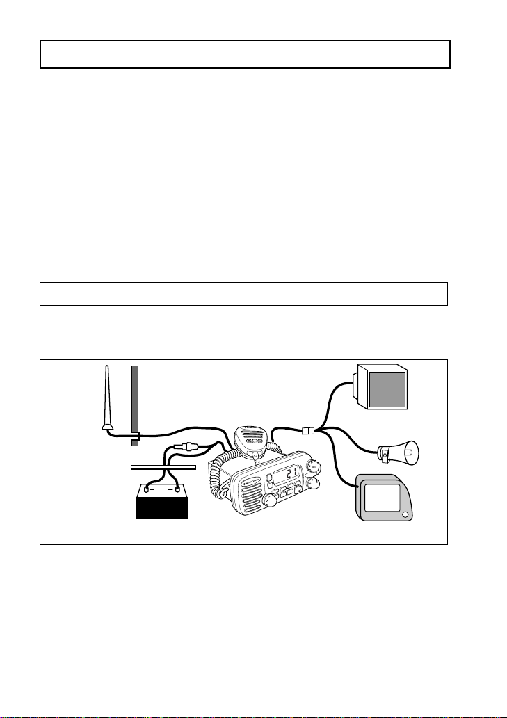
4.2 ELECTRICAL CONNECTIONS
CAUTION
Reverse polarity connections will damage the radio!
Connect the power cord and antenna to the radio. Antenna and Power
Supply connections are as follows (see Figure 2):
Antenna
Water proof
Deck Outlet
Red
Power Source
Fuse
Black
Optional Speaker
Accessory cable
16/9
R
W
/P
L
O
V
A
S
U
I
H
A
9
/
6
1
SPECTRUM
Horizon
G
O
F
/
A
P
X
G
W
O
F
/
A
P
S
S
L
E
R
Q
T
S
S
N
I
E
D
P
L
O
/
L
L
H
U
P
L
L
A
C
/B
T
A
E
S
/
M
E
M
N
A
C
S
Optional Public
Address Speaker
GPS Navigation Receiver
Figure 2. General Installation
1. Mount the antenna at least 3 feet away from the radio. At the rear of
the radio, connect the antenna cable. It must have a PL259
connector. RG-8/U coaxial cable must be used if the antenna is 25
feet or more from the radio. RG58 cable can be used for distances
less than 25 feet.
page 9 Owner’s Manual GX2350S
2. Connect the red power wire to a 13.8 VDC ± 20% power source.
Connect the black power wire to a negative ground.
3. If an optional remote extension speaker is to be used, refer to
section 4.3 for connections.
4. It is advisable to have a Certified Marine Technician check the
power output and the standing wave ratio of the antenna after
installation.
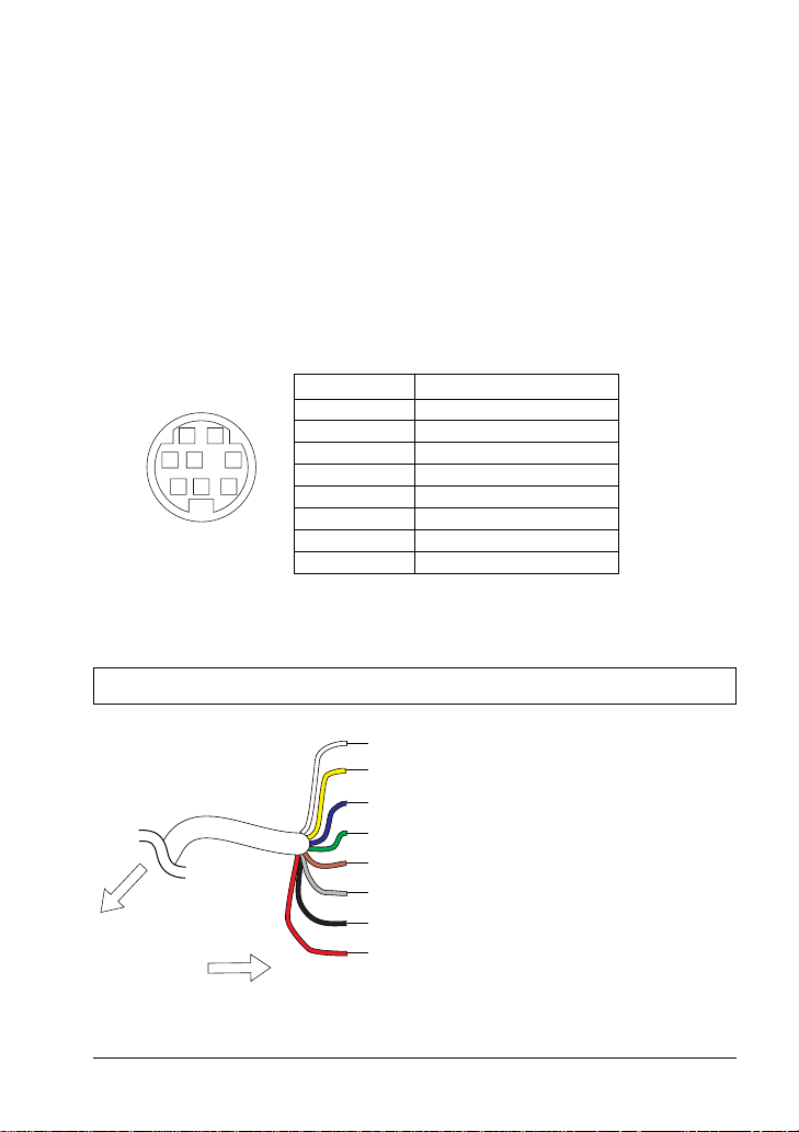
4.3 ACCESSORY CABLE
Cable pin number and signal
Pin number Signal
1 External speaker (+)
12
3
45
67 8
When connecting the external speaker, GPS navigation receiver, or PA
speaker strip off about 1 inch (2 cm) of the specified wire’s insulation.
Never short wires. This may lead to malfunctions.
2 External speaker (–)
3 PA (+)
4 NMEA IN (+)
5 PA (–)
6 NMEA IN (–)
7 NMEA OUT (+)
8 NMEA OUT (–)
NOTE
White: External speaker (+)
Yellow: External speaker (–)
Blue:
Green:
NMEA IN (+) of GPS navigation receiver
NMEA IN (–) of GPS navigation receiver
Brown: NMEA OUT (+)
Gray: NMEA OUT (–)
To GX2350S
Black: PA (–)
Red: PA (+)
To external speaker, PA speaker and GPS receiver
GX2350S Owner’s Manual page 10
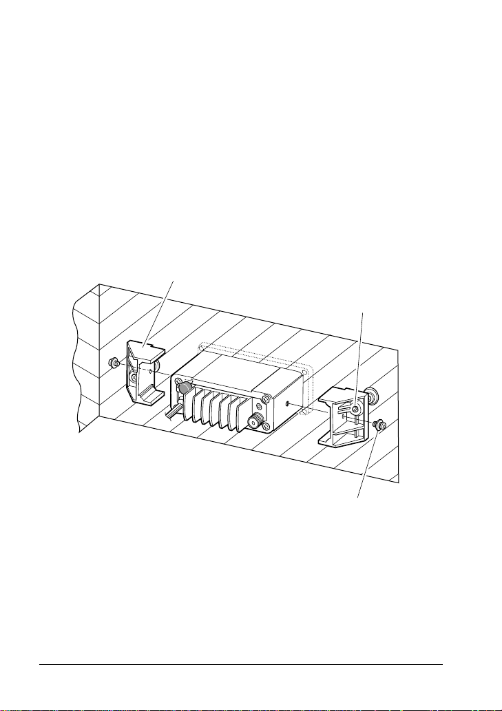
4.4 CMB16 FLUSH MOUNT INSTALLATION
1. Make a rectangular template for the flush mount measuring 2 1/8" H
x 5 3/4" W.
2. Use the template to mark the location where the rectangular hole is
to be cut. Confirm the space behind the dash or panel is deep
enough to accommodate the transceiver (at least 6 inches deep).
There should be at least 1/2 inch between the transceiver’s heatsink
and any wiring, cables or structures.
3. Cut out the rectangular hole and insert the transceiver.
4. Fasten the brackets to the sides of the transceiver with the lock
washer nut combination, so that the mounting screw base faces the
mounting surface (see Figure 3).
5. Turn the adjusting screw to adjust the tension so that the
transceiver is tight against the mounting surface.
Bracket
adjusting screw
Lock-washer nut combination
Figure 3. CMB16 Flush Mount Installation
page 11 Owner’s Manual GX2350S

5 BASIC OPERATION
5.1 RECEPTION
1. After the transceiver has been installed, ensure that the power
supply and antenna are properly connected.
2. Press and hold the VOL/PWR knob until the radio turns on.
3. Turn the SQL knob fully counterclockwise. This state is known as
“squelch off”.
4. Turn up the volume until noise or audio from the speaker is at a
comfortable level.
5. Turn the SQL knob clockwise until the random noise disappears.
This state is known as the “squelch threshold.”
6. Turn the Channel Selector knob to select the desired channel.
Refer to the channel chart in the OWNER’S MANUAL
SUPPLEMENT for available channels.
7. When a message is received, adjust the volume to the desired
listening level. The “BUSY” indicator in the LCD is displayed
indicating that the channel is being used.
5.2 TRANSMISSION
1. Perform steps 1 through 6 of RECEPTION.
2. Before transmitting, monitor the channel to ensure it is clear. THIS
IS AN FCC REQUIREMENT!
3. Press the PTT (push-to-talk) switch. The TX indicator on the LCD is
displayed.
4. Speak slowly and clearly into the microphone.
5. When the transmission is finished, release the PTT switch.
6. Refer to the OWNER’S MANUAL SUPPLEMENT for standard
transceiver operating procedures.
NOTE
This is a noise-canceling microphone. It should be positioned within 1
inch (2 cm) from the mouth for optimum performance.
GX2350S Owner’s Manual page 12
 Loading...