

Standard Horizon GX2000E, GX2100E Owner's Manual

MATRIX SERIES
GX2000E and GX2100E
25 Watt VHF/FM
Marine Transceivers
Owner's Manual
GX2100E: Integrated dual channel AIS (Automatic Identification System) receiver
GX2000E: AIS support with external AIS receiver or transponder
AIS target display includes MMSi, Callsign, Ship Name, BRG, DST,SOG & COG
Select and make automatic DSC call to AIS target
Class D DSC (Digital Selective Calling) with Distress, Individual and All Ship calls
Navigation information (LAT/LONG,SOG,COG) information shown on display
Navigate to a DSC Distress Position
Enter, Save and Naviagate to a waypoing with Compass page
GX2100E output AIS VDM sentence to compatible GPS chart Plotter
Automatic DSC Position Poll request to up to 4 seperate vessels
E2O (Easy to operate ) Menu system with User programmable soft keys on Radio
Dedicated channel 70 receiverfor continous DSC watch
Submersible JIS-7/IPX-7 rating (1Metre for 30 mins)
GX2100E - 30 Watt PA/Loudhailer with pre programmed fog Signals and listenback
facility
ClearVoice noise cancelling microphone with channelselector and 16/9 key
Supports RAM3 Remote station speaker microphone and VLH-310 remote handset as
second remote station
Intercom facility between Remote Station and Radio
AIS and Navigation functions available on RAM3 Remote station speaker microphone
GX2100E requires connection to external GPS or
GX2000E requries connection to external GPS and AIS receiver or Transponder
MATRIX AIS GX2100EMATRIX GX2000E
Page 1GX2000E/GX2100E

TABLE OF CONTENTS
Quick Reference Guide ................................................................................................................................................. 4
1 GENERAL INFORMATION..................................................................................................................................... 8
2 PACKING LIST ....................................................................................................................................................... 9
3 OPTIONS ................................................................................................................................................................. 9
4 SAFETY/WARNING INFORMATION .................................................................................................................... 10
5 GETTING STARTED ............................................................................................................................................ 11
5.1 ABOUT VHF RADIO .............................................................................................................................. 11
5.2 SELECTING AN ANTENNA ................................................................................................................... 11
5.3 COAXIAL CABLE .................................................................................................................................... 12
5.4 EMERGENCY (CHANNEL 16 USE) ........................................................................................................ 13
5.5 CALLING ANOTHER VESSEL (CHANNEL 16 OR 9) ........................................................................... 14
5.6 MAKING TELEPHONE CALLS .............................................................................................................. 14
5.7 OPERATING ON CHANNELS 13 AND 67 .........................................................................................15
6 INSTALLATION ..................................................................................................................................................... 16
6.1 LOCATION ............................................................................................................................................... 16
6.2 MOUNTING THE RADIO ....................................................................................................................... 16
6.3 ELECTRICAL CONNECTIONS .............................................................................................................. 18
6.4 ACCESSORY CABLE ............................................................................................................................. 19
6.5 CHECKING GPS CONNECTIONS ........................................................................................................ 21
6.6 CHANGING THE GPS TIME ................................................................................................................ 22
6.7 CHANGING THE TIME LOCATION...................................................................................................... 23
6.8 CHANGING THE TIME FORMAT ......................................................................................................... 23
6.9 CHANGING COG TO TRUE OR MAGNETIC .................................................................................... 24
6.10 OPTIONAL CMP30 (RAM3) INSTALLATION .......................................................................................... 25
7 CONTROLS AND INDICATORS ......................................................................................................................... 28
8.1 CONTROLS AND CONNECTIONS ....................................................................................................... 28
8 BASIC OPERATION ............................................................................................................................................. 33
8.1 RECEPTION ............................................................................................................................................ 33
8.2 TRANSMISSION ..................................................................................................................................... 33
8.3 TRANSMIT TIME-OUT TIMER (TOT) ................................................................................................... 33
8.4 SIMPLEX/DUPLEX CHANNEL USE ..................................................................................................... 34
8.5 DISPLAY TYPE ....................................................................................................................................... 34
8.6 INTERNATIONAL, CANADA, AND USA MODE .................................................................................. 35
8.7 DUAL WATCH (TO CHANNEL16) .......................................................................................................... 35
8.8 SCANNING .............................................................................................................................................. 36
8.9 PRESET CHANNELS (0 ~ 9): INSTANT ACCESS .............................................................................. 38
8.10 PA/FOG OPERATION ............................................................................................................................. 39
8.11 INTERCOM OPERATION ....................................................................................................................... 42
8.12 VOICE SCRAMBLER ............................................................................................................................. 43
9 DIGITAL SELECTIVE CALLING ......................................................................................................................... 44
9.1 GENERAL ................................................................................................................................................ 44
9.2 MARITIME MOBILE SERVICE IDENTITY (MMSI) ............................................................................... 45
9.2.1 What is an MMSI? ............................................................................................................... 42
9.2.2 Programming the MMSI ........................................................................................................ 45
9.3 DSC DISTRESS CALL .......................................................................................................................... 46
9.3.1 Transmitting a DSC Distress Call .......................................................................................46
9.3.2 Receiving a DSC Distress Call ........................................................................................... 49
9.4 ALL SHIPS CALL ................................................................................................................................... 51
9.4.1 Transmitting an All Ships Call ............................................................................................. 51
9.4.2 Receiving an All Ships Call ................................................................................................. 52
9.5 INDIVIDUAL CALL .................................................................................................................................. 53
9.5.1 Setting up the Individual / Position Call Directory .............................................................. 53
9.5.2 Setting up Individual Reply .................................................................................................. 54
9.5.3 Enabling the Individual Acknowledgment ............................................................................ 54
9.5.4 Setting up Individual / Group Call Ringer ........................................................................... 55
9.5.5 Transmitting an Individual Call ............................................................................................ 56
9.5.6 Receiving an Individual Call ................................................................................................ 58
9.6 DSC LOG OPERATION ......................................................................................................................... 59
9.6.1 Reviewing a Logged DSC Distress Call ............................................................................ 59
9.6.2 Reviewing a Logged All Ship or Individual Call ............................................................... 60
9.6.3 Deleting a Call from the "DSC LOG" Directory ................................................................ 61
9.7 GROUP CALL ......................................................................................................................................... 62
9.7.1 Setting up a Group Call ...................................................................................................... 62
9.7.2 Transmitting a Group Call .................................................................................................... 63
9.7.3 Receiving a Group Call ........................................................................................................ 65
9.8 POSITION REQUEST ............................................................................................................................ 66
9.8.1 Setting up a Position Reply ................................................................................................. 66
9.8.2 Setting up a Position Request Ringer ................................................................................ 67
9.8.3 Transmitting a Position Request to Another Vessel .......................................................... 67
9.8.4 Receiving a Position Request .............................................................................................. 68
1. Accepting to auto switching to channel 16 .......................................................................... 49
2. Pausing the auto switching to channel 16 .......................................................................... 49
3. Quit to exit to the working channel ..................................................................................... 49
1. Accepting to auto switching to channel 16 .......................................................................... 52
2. Pausing the auto switching to channel 16 .......................................................................... 52
3. Quit to exit to the working channel ..................................................................................... 52
GX2000E/GX2100EPage 2

TABLE OF CONTENTS
9.9 POSITION REPORT ............................................................................................................................... 70
9.9.1 Setting up a DSC Position Report Ringer ......................................................................... 70
9.9.2 Transmitting a DSC Position Report Call .......................................................................... 70
9.9.3 Receiving a DSC Position Report Call .............................................................................. 72
9.9.4 Navigating to a Position Report .......................................................................................... 72
9.10 MANUAL INPUTTING OF THE GPS LOCATION (LAT/LON) ............................................................ 74
9.11 AUTO DSC POLLING .............................................................................................................................. 75
9.11.1 Selecting Stations to be Automatically Polled (tracked).................................................... 75
9.12.2 Enable/Disable Auto DSC Polling ........................................................................................76
9.12 DSC TEST .............................................................................................................................................. 77
9.12.1 Programming MMSI into Individual Directory ..................................................................... 77
9.12.2 DSC Test Call by using Individual Directory ..................................................................... 77
10 GENERAL SETUP ................................................................................................................................................ 79
11 CHANNEL FUNCTION SETUP ........................................................................................................................... 88
12 DSC SETUP ......................................................................................................................................................... 95
13 AIS / COMPASS SETUP .................................................................................................................................... 101
14 WAYPOINTS ........................................................................................................................................................ 107
15 ATIS SETUP ....................................................................................................................................................... 112
16 CMP30 (RAM3) REMOTE MIC OPERATION ................................................................................................. 114
17 MAINTENANCE ................................................................................................................................................... 118
18 CHANNEL ASSIGNMENTS ............................................................................................................................... 120
19 SPECIFICATIONS ............................................................................................................................................... 122
20 RESET PROCEDURES ...................................................................................................................................... 125
9.12.3 DSC Test Call by Manually Entering MMSI ....................................................................... 78
10.1 DISPLAY .................................................................................................................................................. 79
10.2 LOCAL DISTANCE RECEIVER ATTENUATOR ................................................................................... 80
10.3 BACKLIGHT ADJUSTMENT .................................................................................................................. 81
10.4 DISPLAY CONTRAST ............................................................................................................................ 81
10.5 TIME OFFSET ........................................................................................................................................ 82
10.6 TIME AREA ............................................................................................................................................. 83
10.7 TIME DISPLAY ....................................................................................................................................... 83
10.8 UNIT OF MEASURE .............................................................................................................................. 84
10.9 MAGNETIC .............................................................................................................................................. 85
10.10 KEY BEEP .............................................................................................................................................. 85
10.11 FOG ALERT TONE FREQUENCY ....................................................................................................... 86
10.12 SOFT KEYS ............................................................................................................................................ 87
11.1 CHANNEL GROUP ................................................................................................................................. 88
11.2 SCAN MEMORY ..................................................................................................................................... 88
11.3 SCAN TYPE ............................................................................................................................................ 89
11.4 SCAN RESUME ...................................................................................................................................... 89
11.5 PRIORITY CHANNEL ............................................................................................................................. 90
11.6 CHANNEL NAME ................................................................................................................................... 91
11.7 STATION NAME ..................................................................................................................................... 92
11.8 SCRAMBLER SETUP ............................................................................................................................. 93
11.9 DEMO MODE ......................................................................................................................................... 94
12.1 INDIVIDUAL DIRECTORY ...................................................................................................................... 95
12.2 INDIVIDUAL REPLY ............................................................................................................................... 96
12.3 INDIVIDUAL ACKNOWLEDGMENT ....................................................................................................... 96
12.4 INDIVIDUAL RINGER ............................................................................................................................. 97
12.5 GROUP DIRECTORY ............................................................................................................................. 97
12.6 POSITION REPLY .................................................................................................................................. 99
12.7 DSC BEEP ............................................................................................................................................ 100
13.1 AUTOMATIC IDENTIFICATION SYSTEM (AIS) ................................................................................. 101
13.2 DIRECTION ........................................................................................................................................... 102
13.3 ACTIVATION RANGE ........................................................................................................................... 102
13.4 CPA ALARM .......................................................................................................................................... 103
13.5 TCPA ALARM ........................................................................................................................................ 103
13.6 DISPLAY RANGE ................................................................................................................................. 104
13.7 AIS OPERATION .................................................................................................................................. 105
13.8 AIS RANGE .......................................................................................................................................... 106
14.1 MARKING A POSITION ....................................................................................................................... 107
14.2 ADDING A WAYPOINT ........................................................................................................................ 108
14.3 EDITING A WAYPOINT ....................................................................................................................... 109
14.4 DELETING A WAYPOINT .................................................................................................................... 109
14.5 SAVING A DSC POSITION CALL AS A WAYPOINT ...................................................................... 110
14.6 NAVIGATING TO A SAVED WAYPOINT ............................................................................................ 110
14.7 STOP NAVIGATING TO A WAYPOINT .............................................................................................. 111
15.1 ATIS CH GROUP ................................................................................................................................. 112
15.2 ATIS CODE PROGRAMMING ............................................................................................................. 113
16.1 REMOTE MIC CONTROLS ................................................................................................................ 114
16.2 ASSIGNING SOFT KEYS ................................................................................................................... 116
17.1 REPLACEMENT PARTS ...................................................................................................................... 118
17.2 FACTORY SERVICE ............................................................................................................................ 117
17.3 TROUBLESHOOTING CHART ............................................................................................................ 119
Page 3GX2000E/GX2100E
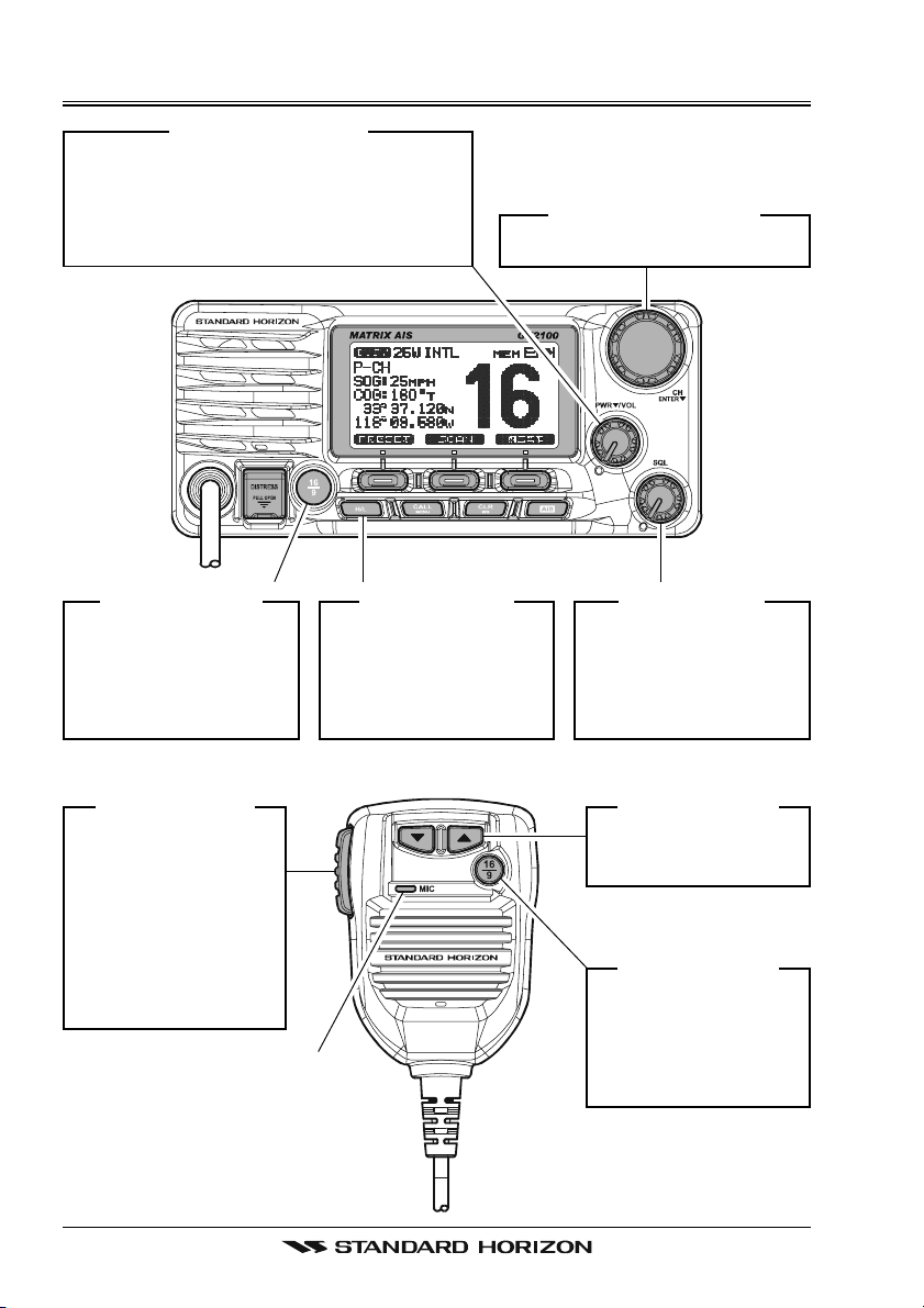
QUICK REFERENCE GUIDE
[
PWR/VOL] K
Press and hold this knob to turn on or off
the radio. When the radio is on, turning
this knob will adjust the speaker audio
volume.
NOB
[
CH/ENTER] K
Selects the operating channel.
NOB
[
16/9] B
Press to recall chan-
nel 16.
Press and hold to
recall channel 9.
[
PTT] S
Place your mouth
about 1/2 inch away
from Mic hole and
speak in a normal
voice level while
pressing this
switch.
UTTON
WITCH
[
H/L] B
When pressed,
toggles the transmit
power between High
(25W) and Low (1W).
MIC H
OLE
UTTON
[
SQL] K
Move this control
clockwise to squelch
or counter clockwise
un-squelch the radio.
[]
Selects the operating
channel.
[
16/9] B
Press to recall
channel 16.
Press and hold to
recall channel 9.
NOB
/ [] K
UTTON
EY
GX2000E/GX2100EPage 4
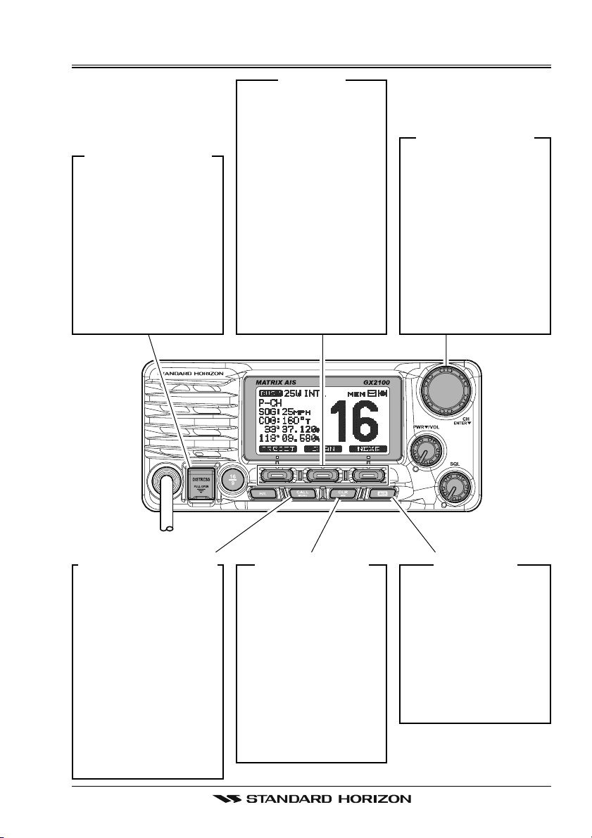
QUICK REFERENCE GUIDE
[
DISTRESS] B
Note: for this key to
operate a MMSI must
be programmed.
To transmit a DSC Distress call, lift the red
cover, press the Distress button once,
then press and hold
until the radio alarms.
UTTON
[
]
S
OFT
K
EY
The 3 soft keys underneath the display can
be customized, refer
to section “10.12
SOFT KEYS”.
The factory defaults
are Key 1: [PRESET], 2:
[
SCAN], and 3: [NEXT
key. Pressing the
[
NEXT] soft key will
show Key 1: [DW],
Key 2: [PA/FOG], Key
3: [NEXT].
[
CH/ENTER] K
Selects a Marine
VHF channel.
Selects the item in
the “SETUP MENU”
]
and “DSC MENU”.
When the “SETUP
MENU” or “DSC
MENU” is selected,
pressing this knob
enters a selection.
NOB
[
CALL/MENU] B
Press to access the
“DSC MENU”, refer
to section “9 DIGI-
TAL SELECTIVE
CALLING”.
Press and hold to
access the “SETUP
MENU”, refer to
section “10 GEN-
ERAL SETUP
MODE”.
UTTON
[
CLR/WX] B
Press to cancel a
menu selection.
The WX function
does not work in this
model (USA/EXP
model only).
If you need to operate the WX function,
please contact your
dealer.
UTTON
[
AIS] B
UTTON
Press to change the
display to AIS (Automatic Identification
System) mode.
To setup AIS features,
refer to section “13
AIS / COMPASS
SETUP”.
Page 5GX2000E/GX2100E
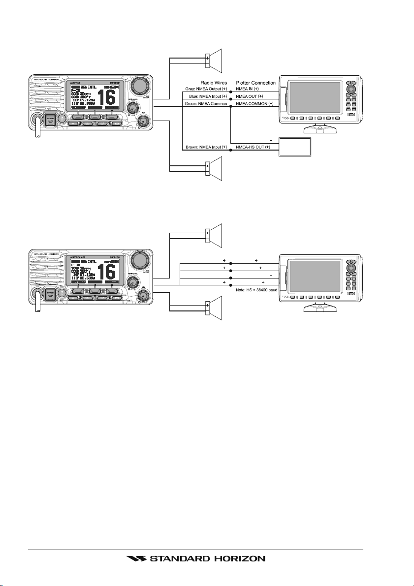
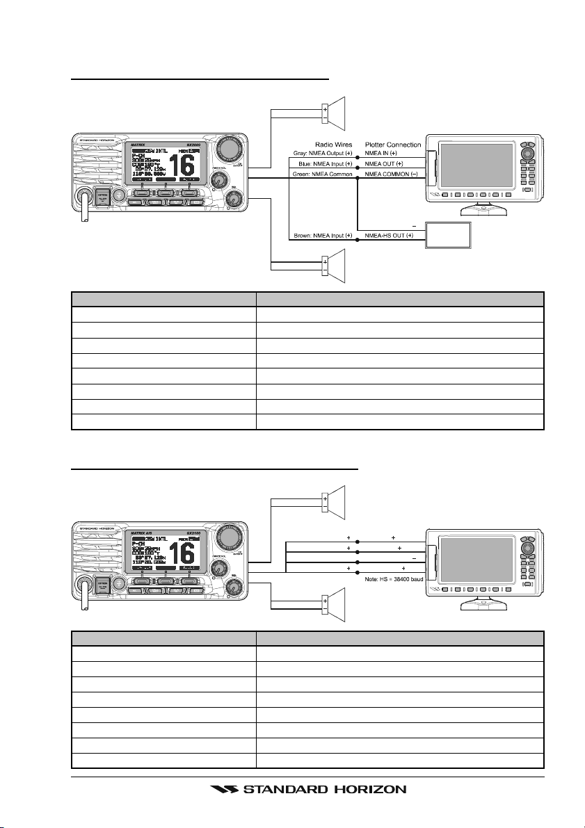
ELECTRICAL CONNECTIONS
Red
Shield
Whit e
Shield
PA Speak er
NMEA COMMON
External Speaker
MATRIX GX2000E
Red
Shield
Gray: NMEA Output
Blue: NMEA Input
Green: NMEA Common
Brown: NMEA Output
Whit e
Shield
Radio Wi res
PA Speak er
Plotter Connection
( )
NMEA IN
( )
NMEA OUT
NMEA COMMON
( )
NMEA-HS IN
External Speaker
MATRIX AIS GX2100E
( )
( )
( )
GPS Receiver/Chart Plotter
( )
AIS Receiver
Note: HS = 38400 baud
GPS Receiver/Chart Plotter
( )
GX2000E/GX2100EPage 6
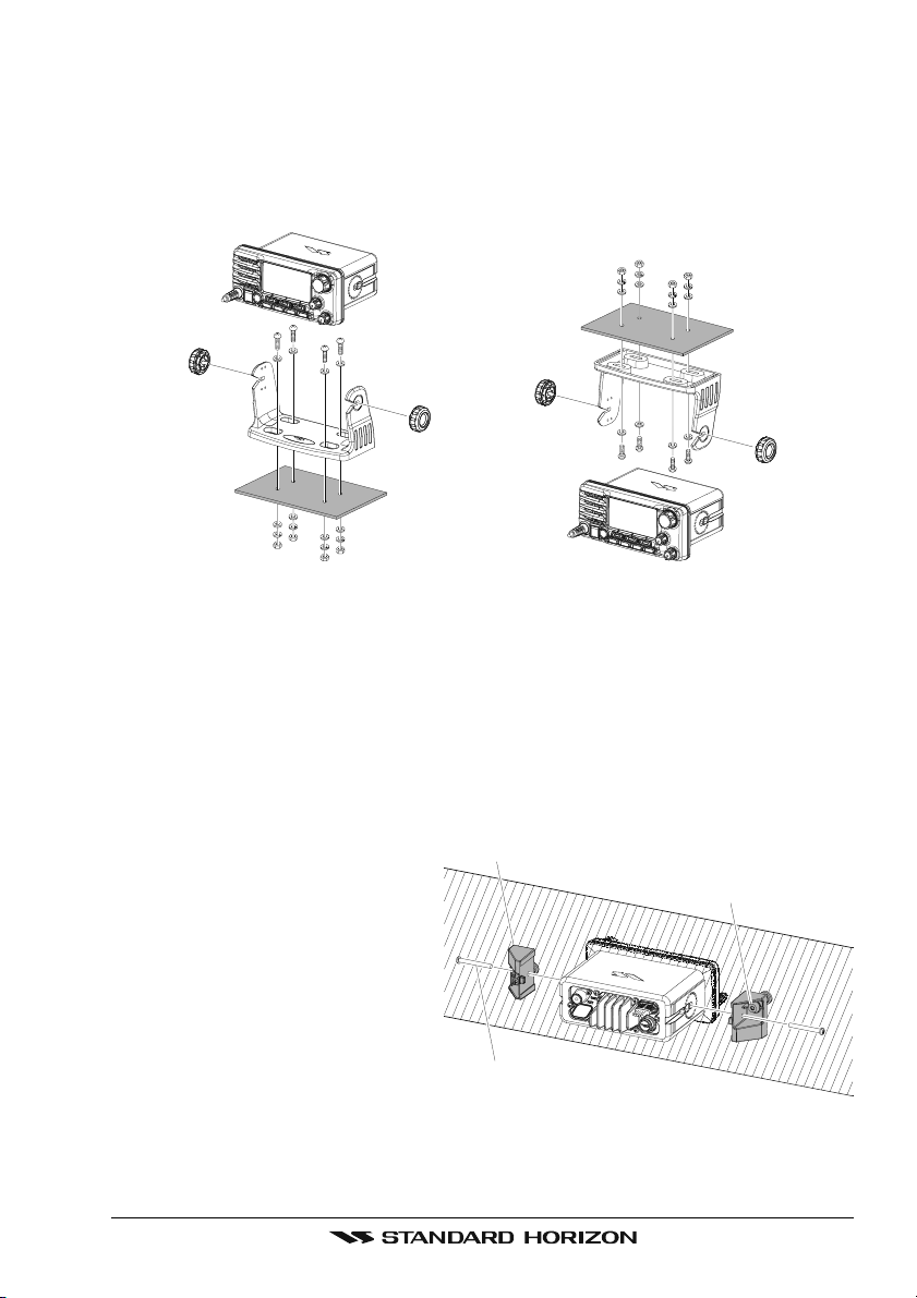
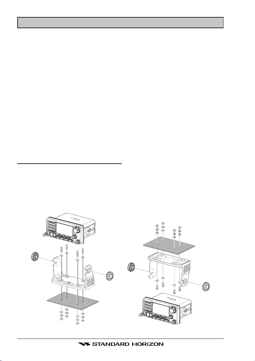
DESKTOP/OVERHEAD MOUNTING THE RADIO
The supplied universal mounting bracket allows desktop or overhead mounting.
Use a 5-mm bit to drill the holes to a surface which is more 10 mm thick and
can support more than 1.5 kg and secure the bracket with the supplied screws,
spring washers, flat washers, and nuts.
DESKTOP MOUNTING OVERHEAD MOUNTING
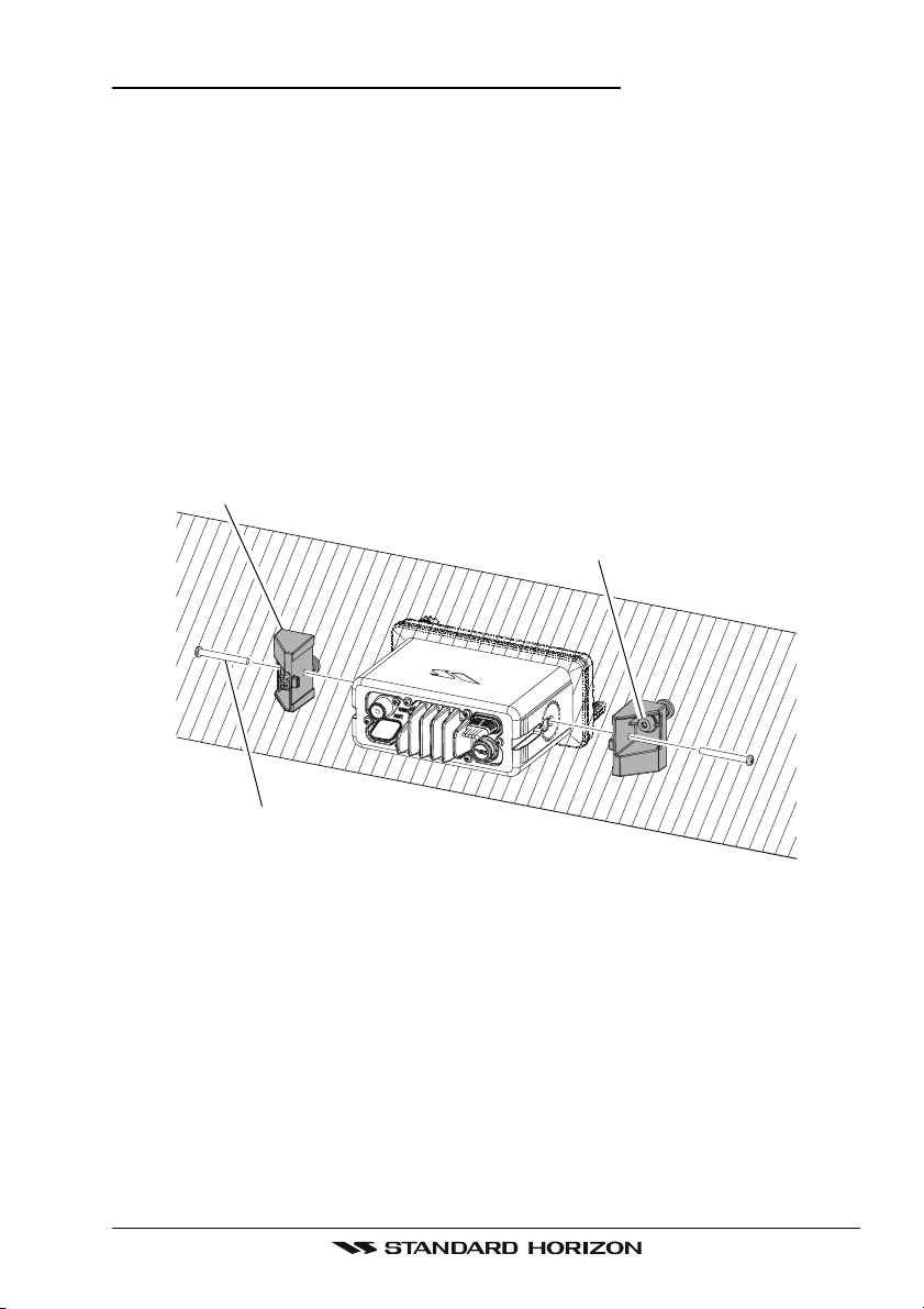
FLUSH MOUNTING THE RADIO
The optional MMB-84 Flush-Mount Bracket allows flush mounting the radio on
your vessel.
1. Use the supplied template to mark the location where the rectangular hole
is to be cut. Confirm the space behind the dash or panel is deep enough to
accommodate the transceiver (at least 17 cm deep).
There should be at least 1.5
Bracket
cm between the transceiver’s
heatsink and any wiring,
Adjusting Screw
cables or structures.
2. Cut out the rectangular hole
and insert the transceiver.
3. Fasten the optional MMB-84
brackets to the sides of the
transceiver with the lock
Lock-washer screw combination
washer screw combination; so
that the mounting screw base faces the mounting surface.
4. Turn the adjusting screw on each bracket to adjust the tension so that the
transceiver is tight against the mounting surface.
Page 7GX2000E/GX2100E

1 GENERAL INFORMATION
The STANDARD HORIZON MATRIX Series GX2000E and GX2100E Marine
VHF/FM Marine transceiver are designed to be used in International, Canadian, and USA Marine bands. The GX2000E and GX2100E can be operated
from 11 to 16 VDC and has a switchable RF output power of 1 watt or 25 watts.
MATRIX AIS GX2100
Integrates a dual channel AIS (Automatic Identification System) receiver to
display AIS vessel information (MMSI, Call Sign, Ship Name, BRG, DST, SOG
and COG) directly on the VHF radio, so you will know what is out there in any
conditions. The GX2100E is also capable of entering and saving up to 100
waypoints, which may be selected and navigated to by using a unique navigation compass display. The MATRIX AIS allows you to contact an AIS Ship
directly using DSC, show your vessels position in relation to AIS targets and
alert you when an AIS ship may be approaching too close to your location via
the Closest Point of Approach (CPA) Alarm. To receive AIS targets from ships
with AIS class A or B transponders, simply connect the normal VHF antenna
(only one antenna needed!)
MATRIX - GX2000E
For the mariner who already has AIS on-board and desires a VHF with the
features of the MATRIX AIS, the MATRIX GX2000E has a connection for an
AIS receiver or transponder.
The MATRIX Series VHF’s are capable of DSC (Digital Selective Calling) Class
D operation. Class D operation allows continuous receiving of Digital Selective
Calling functions on channel 70 even if the radio is receiving a call. The MATRIX Series VHF’s operate on all currently-allocated marine channels which
are switchable for use with International, Canadian, or USA regulations. Emergency channel 16 can be immediately selected from any channel by pressing
the red [16/9] key.
Other features of the MATRIX Series VHF’s include: Speaker Microphone,
30W PA/Fog, optional RAM3 second station remote-control microphone with
display, intercom between radio and optional RAM3, scanning, priority scanning, submersible speaker mic, high and low voltage warning, and GPS repeatability.
The MATRIX series also support ATIS modoe, which is used in the inland
waterways of Europe. Please contact your local PTT adminstratioon or Marine
Authority to obtain your ATIs number.
ATIS operation is explained in Chapter 15 of this user manual.
GX2000E/GX2100EPage 8

2 PACKING LIST
When the package containing the transceiver is first opened, please check it
for the following contents:
GX2000E or GX2100E Transceiver
Power Cord
Mounting Bracket and hardware
Owner’s Manual
Warranty Card
Flush Mount Template
3 OPTIONS
MMB-84 ......................................................................... Flush-Mount Bracket
CMP30B/W ............... Remote-Access Microphone (RAM3 Mic, Black/White)
CT-100 .................................................... 7 m Extension Cable for RAM3 Mic
CVS2500 ...............................................................................Voice Scrambler
MLS-310 ............ 10W amplified External Speaker with on/off Volume control
MLS-300 .................................................................... External Loud Speaker
220SW ................................................................. 12 cm Round Hail/PA Horn
240SW ................................................. 13 x 20 cm Rectangular Hail/PA Horn
Page 9GX2000E/GX2100E

4 SAFETY / WARNING INFORMATION
IMPORTANT SAFETY INFORMATION
Please read this manual carefully to become familiar with the features
of this transceiver before using it for the first time.
The installation of this equipment should be made in such a manner as to
respect the EC recommended electromagnetic field exposure limits (1999/519/
EC).
The maximum RF power available from this device is 25 W. The antenna should
be mounted as high as possible for maximum efficiency and that this installation height should be at least 5 meters above ground (or accessible) level. In
the case that an antenna can not be installed at a reasonable height, then the
transmitter should neither be continuously operated for long periods if any
person is within 5 metres of the antenna, nor operated at all if any person is
touching the antenna. non compliance with these recommendations and transmitting for more than 50% of the total radio use time (50 % duty cycle) may
cause RF complaince exposure requirements to be be exceeded.
In all cases any possible risk depends on the transmitter being activated for
long periods (actual recommendation limits are specified as an average of 6
minutes). Normally the transmitter is not active for long periods of time. Some
radio licenses will require that a timer circuit automatically cuts the transmitter
after 1 - 2 minutes.
Do not transmit without an antenna connected to the radio. When transmitting
speak into the microphone holding it between 1.5 cm and 5 cm from your
mouth.
The radio must be used with a maximum operating duty cycle not exceeding
50 % in normal PTT configurations. Do not transmit for more than 50 % of the
total radio use time (50 % duty cycle)
GX2000E/GX2100EPage 10

5 GETTING STARTED
5.1 ABOUT VHF RADIO
The radio frequencies used in the VHF marine band lie between 156 and 162
MHz. The marine VHF band provides communications over distances that are
essentially “line of sight” (VHF signals do not travel well through objects such
as buildings, hills or trees). Actual transmission range depends much more on
antenna type, gain and height than on the power output of the transmitter. On
a fixed mount 25 W radio transmission expected distances can be greater
than 25 km, for a portable 5W radio transmission the expected distance can
be greater than 8 km in “line of sight”.
5.2 SELECTING AN ANTENNA
Marine antennas are made to radiate signals equally in all horizontal directions, but not straight up. The objective of a marine antenna is to enhance the
signal toward the horizon. The degree to which this is accomplished is called
the antenna’s gain. It is measured in decibels (dB) and is one of the major
factors in choosing an antenna. In terms of effective radiated power (ERP),
antennas are rated on the basis of how much gain they have over a theoretical
antenna with zero gain. A 1 m, 3 dB gain antenna represents twice as much
gain over the imaginary antenna.
Typically a 1 m 3 dB gain stainless steel whip is used on a sailboat mast. The
longer 2.5 m 6 dB fiberglass whip is primarily used on power boats that require
the additional gain.
Page 11GX2000E/GX2100E
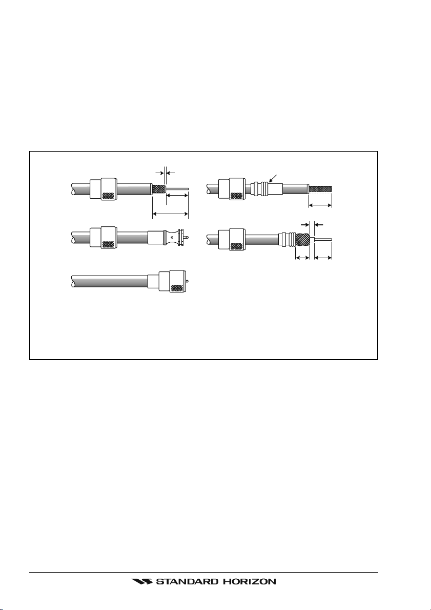
5.3 COAXIAL CABLE
VHF antennas are connected to the transceiver by means of a coaxial cable –
a shielded transmission line. Coaxial cable is specified by it’s diameter and
construction.
For runs less than 6 m, RG-58/U, about 1/4 inch in diameter is a good choice.
For runs over 6 m but less than 15 m, the larger RG-8X or RG-213/U should be
used for cable runs over 15 m RG-8X should be used. For installation of the
connector onto the coaxial cable refer to the figure below.
2 mm
1/16''
3/4''
20 mm
30 mm
1 1/8''
Adapter
1/8''
3 mm
10 mm 15 mm
3/4''
20 mm
5/8''3/8''
To get your coax cable through a fitting and into your boat’s interior, you
may have to cut off the end plug and reattach it later. You can do this if
you follow the directions that come with the connector. Be sure to make
good soldered connections.
GX2000E/GX2100EPage 12

5.4 EMERGENCY (CHANNEL 16 USE
Channel 16 is known as the Hail and Distress Channel. An emergency may be
defined as a threat to life or property. In such instances, be sure the transceiver
is on and set to CHANNEL 16. Then use the following procedure:
1. Press the microphone push-to-talk switch and say “Mayday, Mayday, May-
day. This is , , ” (your vessel’s name).
2. Then repeat once: “Mayday, ” (your vessel’s name).
3. Now report your position in latitude/longitude, or by giving a true or magnetic bearing (state which) to a well-known landmark such as a navigation
aid or geographic feature such as an island or harbor entry.
4. Explain the nature of your distress (sinking, collision, aground, fire, heart
attack, life-threatening injury, etc.).
5. State the kind of assistance your desire (pumps, medical aid, etc.).
6. Report the number of persons aboard and condition of any injured.
7. Estimate the present seaworthiness and condition of your vessel.
8. Give your vessel’s description: length, design (power or sail), color and
other distinguishing marks. The total transmission should not exceed 1
minute.
9. End the message by saying “OVER”. Release the microphone button and
listen.
10. If there is no answer, repeat the above procedure. If there is still no response, try another channel.
)
NOTE
The GX2000E and GX2100E have DSC Distress calling, that can transmit a distress call digitally to all ships with compatible DSC radios. Refer
to section “9 DIGITAL SELECTIVE CALLING”.
Page 13GX2000E/GX2100E

5.5 CALLING ANOTHER VESSEL (CHANNEL 16 OR 9
Channel 16 should be used as the calling channel for initial contact with another vessel, however its primary purpose is for emergency communications
and should be monitored at all times when not using other channels.
It is monitored by Coast Guard stations in all countries and other vessels.
The use of Channel 16 should be limited to making initial contact only. Calling
should not exceed 30 seconds, but may be repeated at 2 minute intervals.
Prior to making contact with another vessel, refer to the channel charts in this
manual and select an appropriate channel (working channel) for use after initial contact. Monitor the proposed channel to ensure you will not be interruptng
other traffic and then go back to Channel 16 to make your initial call.
When the calling chqannel 16 is clear, state the name of the vessel you wish to
call and then “this is” followed by the name of your vessel and your vessel
callsign. When the other vessel returns your call, immediately request another
channel by saying “go to”, the number of the other channel, and “over”. Then
switch to the new channel. When the new channel is not busy, call the other
vessel.
After a transmission, say “over”, and release the PTT (Push-To-Talk) switch.
When all communication with the other vessel is completed, end the last transmission by stating your Call Sign and the word “out”. Note that it is not necessary to state your Call Sign with each transmission, only at the beginning and
end of the contact.
)
Remember to return to Channel 16 when not using another channel. Some
radios automatically monitor Channel 16 even when set to other channels or
when scanning.
5.6 MAKING TELEPHONE CALLS
To make a radiotelephone call, use a channel designated for this purpose, The
fastest way to learn which channels are used for radiotelephone traffic is to
ask at a local marina. Channels available for such traffic are designated Pub-
lic Correspondence channels on the channel charts in this manual. Some
examples for USA use are Channels 24, 25, 26, 27, 28, 84, 85, 86, and 87.
Call the marine operator and identify yourself by your vessel’s name, The marine
operator will then ask you how you will pay for the call (telephone credit card,
collect, etc.) and then link your radio transmission to the telephone lines.
The marine telephone company managing the VHF channel you are using
may charge a link-up fee in addition to the cost of the call.
GX2000E/GX2100EPage 14

5.7 OPERATING ON CHANNELS 13 AND 67
Channel 13 is used at docks and bridges and by vessels maneuvering in port.
Messages on this channel must concern navigation only, such as meeting and
passing in restricted waters.
Channel 67 is used for navigational traffic between vessels.
By regulation, power is normally limited to 1 Watt on these channels. Your
radio is programmed to automatically reduce power to this limit on these channels. However, in certain situations it may be necessary to temporarily use a
higher power. See page 30 ([H/L] key) for means to temporarily override the
low-power limit on these two channels.
Page 15GX2000E/GX2100E
6 INSTALLATION
6.1 LOCATION
The radio can be mounted at any angle. Choose a mounting location that:
• is far enough from any compass to avoid any deviation in compass reading due to the speaker magnet
• provides accessibility to the front panel controls
• allows connection to a power source and an antenna
• has nearby space for installation of a microphone hanger
• choose a mounting location that is at least 1 m away from the radio’s
antenna.
Note: To insure the radio does not affect the compass or radios performance is
not affected by the antenna location, temporarily connect the radio in the desired location and:
a. Examine the compass to see if the radio causes any deviation
b. Connect the antenna and key the radio. Check to ensure the radio is
operating correctly by requesting a radio check.
6.2 MOUNTING THE RADIO
6.2.1 Supplied Mounting Bracket
The supplied mounting bracket allows overhead or desktop mounting.
Use a 5 mm bit to drill the holes to a surface which is more 10 mm thick and
can support more than 1.5 kg and secure the bracket with the supplied screws,
spring washers, flat washers, and nuts.
DESKTOP MOUNTING OVERHEAD MOUNTING
GX2000E/GX2100EPage 16
6.2.2 Optional MMB-84 Flush Mount Bracket
1. Make a rectangular template for the flush mount measuring 65 x 161 mm.
2. Use the template to mark the location where the rectangular hole is to be
cut. Confirm the space behind the dash or panel is deep enough to accommodate the transceiver (at least 17 cm deep).
There should be at least 1.5 cm between the transceiver’s heatsink and
any wiring, cables or structures.
3. Cut out the rectangular hole and insert the transceiver.
4. Fasten the brackets to the sides of the transceiver with the lock washer
screw combination; so that the mounting screw base faces the mounting
surface (see illustration below).
5. Turn the adjusting screw to adjust the tension so that the transceiver is
tight against the mounting surface.
Bracket
Adjusting Screw
Lock-washer screw combination
Page 17GX2000E/GX2100E
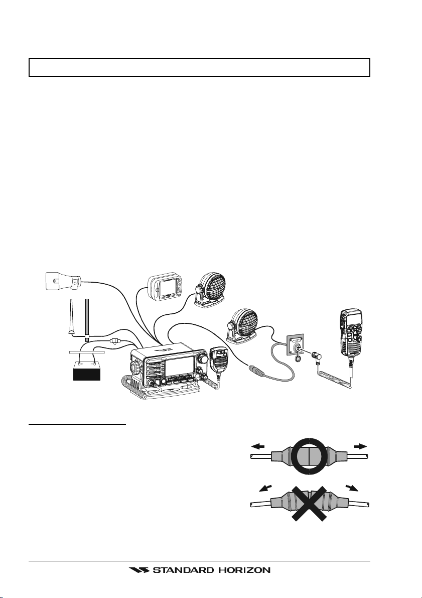
6.3 ELECTRICAL CONNECTIONS
CAUTION
Reverse polarity battery connections will damage the radio!
Connect the power cord and antenna to the radio. Antenna and Power Supply
connections are as follows:
1. Mount the antenna at least 1 m away from the radio. At the rear of the
radio, connect the antenna cable. The antenna cable must have a PL259
connector attached. RG-8/U coaxial cable must be used if the antenna is
7.6 m or more from the radio. RG58 cable can be used for distances less
than 7.6 m.
2. Connect the red power wire to a 13.8 VDC ±20% power source. Connect
the black power wire to a negative ground.
3. If an optional remote extension speaker is to be used, refer to section 6.4
for connections.
4. It is advisable to have a Certified Marine Technician check the power output and the standing wave ratio of the antenna after installation.
Optional HAIL/PA Horn
Antenna
A
c
c
e
s
Water proof
Deck Outlet
GPS Navigation Receiver
s
o
r
y
C
a
b
l
e
Fuse
Optional Speaker
Optional Speaker
Optional CMP30 Remote MIC
Red
Black
Power Source
Fuse Replacement
To take out the Fuse from the Fuse Holder, hold
both ends of the Fuse Holder and pull the Fuse
Holder apart without bending the fuse Holder.
When you replace the Fuse, please confirm that
the Fuse is tightly fixed on the metal contact located inside the Fuse Holder. If the metal contact
holding the fuse is loose, the Fuse holder may
heat up.
GX2000E/GX2100EPage 18
6.4 ACCESSORY CABLE
6.4.1 MATRIX GX2000E Connection
Red
Shield
Whit e
Shield
Wire Color/Description
WHITE - External Speaker (+
SHIELD - External Speaker
RED - PA Speaker (+
SHIELD - PA Speaker
)
(–)
GREEN - NMEA Ground
BLUE - NMEA GPS Input (+
GRAY - NMEA DSC Output (+
BROWN - AIS DATA Input (+
Connection Examples
)
Connect to external 4 Ohm audio speaker
(–)
Connect to external 4 Ohm audio speaker
Connect to external 4 Ohm PA speaker
Connect to external 4 Ohm PA speaker
Connect to NMEA
)
Connect to NMEA (+) output of GPS
)
Connect to NMEA (+) input of GPS
)
Connect to NMEA 38.4K baud (+) output of AIS receiver
6.4.2 MATRIX AIS GX2100E Connection
Red
Shield
Radio Wi res
Gray: NMEA Output
Blue: NMEA Input
Green: NMEA Common
Brown: NMEA Output
( )
( )
( )
PA Speak er
NMEA COMMON
External Speaker
(–)
PA Speak er
Plotter Connection
NMEA IN
NMEA OUT
NMEA COMMON
NMEA-HS IN
( )
connection of GPS
( )
( )
( )
( )
GPS Receiver/Chart Plotter
AIS Receiver
Note: HS = 38400 baud
GPS Receiver/Chart Plotter
Wire Color/Description
WHITE - External Speaker (+
SHIELD - External Speaker
RED - PA Speaker (+
SHIELD - PA Speaker
(–)
)
(–)
GREEN - NMEA Ground
BLUE - NMEA GPS Input (+
)
GRAY - NMEA DSC Output (+
BROWN - AIS DATA Output (+
Whit e
Shield
External Speaker
Connection Examples
)
Connect to external 4 Ohm audio speaker
Connect to external 4 Ohm audio speaker
Connect to external 4 Ohm PA speaker
Connect to external 4 Ohm PA speaker
Connect to NMEA
(–)
connection of GPS
Connect to NMEA (+) output of GPS
)
Connect to NMEA (+) input of GPS
)
Connect to NMEA 38.4K baud (+) input of GPS
Page 19GX2000E/GX2100E
When making connections between the radio, chartplotter, GPS or AIS receiver or AIS transponder, ensure that the connections are robust and protected from shorting toether or to ground. Whether flush mounting the radio or
not, it is recommended that a waterproof 8 position screw terminal connector
block is fixed to the bulkhead adjacent to the rear of the radio and the connections to and from the radio are made via this connector block.
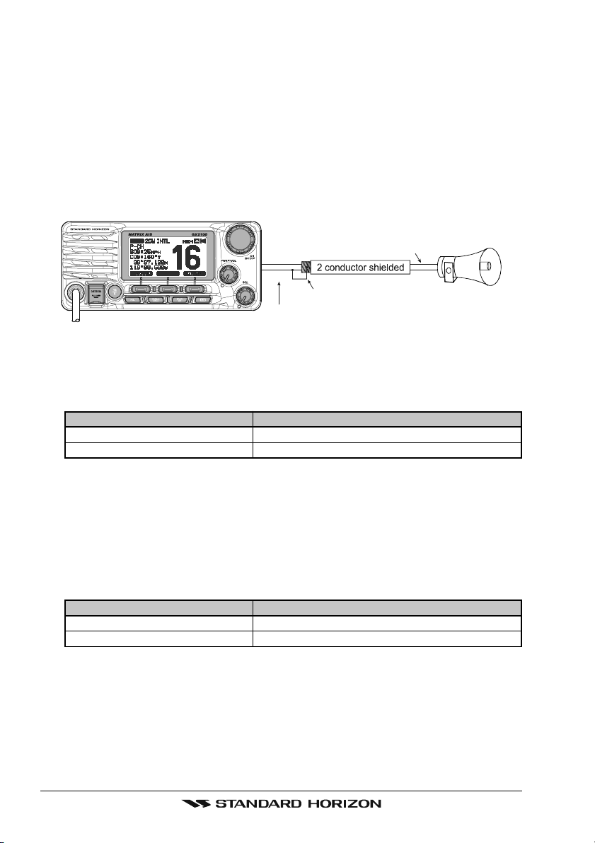
Note: In some areas powerful AM broadcast stations may be heard when in
listen-back mode. In this case change the speaker wire to 2-conductor shielded
audio cable. See the illustration below for connections.
Shield of cable is not
Red
Bare
Make Red and bare connecti ons short as possi ble
attached on PA Speaker end
Connect the bare wire from the GX2000/GX2100
to one wire and to the shielded.
PA Speaker
GPS Connections (4800 baud)
NMEA INPUT (GPS Information)
• The GPS must have the NMEA Output turned on and set to 4800 Baud in
the setup menu. If there is a selection for PARITY select NOTE.
Wire Color/Description
BLUE - NMEA GPS Input (+
GREEN - NMEA Ground
Connection
)
GPS NMEA output
GPS common
• For further information on interfacing /setting up your GPS. Please contact
the manufacturer of the GPS receiver.
• GX2000E/GX2100E can read NMEA-0183 version 2.0 or higher.
• The NMEA 0183 input sentences are GLL, GGA, RMC and GNS (RMC
sentence is recommended).
NMEA Output (DSC)
The NMEA 0183 output sentences are DSC and DSE.
Wire Color/Description
GRAY - NMEA DSC Output (+
GREEN - NMEA Ground
Connection
)
Chart plotter NMEA input
Chart plotter common
GX2000E/GX2100EPage 20
AIS Connections (38400 baud only)
The MATRIX GX2000E (without internal AIS receiver) may be connected to an
external AIS receiver or transponder that outputs NMEA VDM sentence at
38400 baud.
Wire Color/Description
BROWN - AIS Input (+
GREEN - NMEA common
)
Connection
AIS output
AIS common data wire or NMEA signal
(–)
The MATRIX AIS GX2100E with internal dual channel AIS receiver has the
capability to output received Class A and B targets using VDM sentence at a
baud rate of 38400.
Wire Color/Description
BROWN - AIS Output (+
GREEN - NMEA common
)
Connection
GPS Chart plotter input
GPS common data wire or NMEA signal
(–)
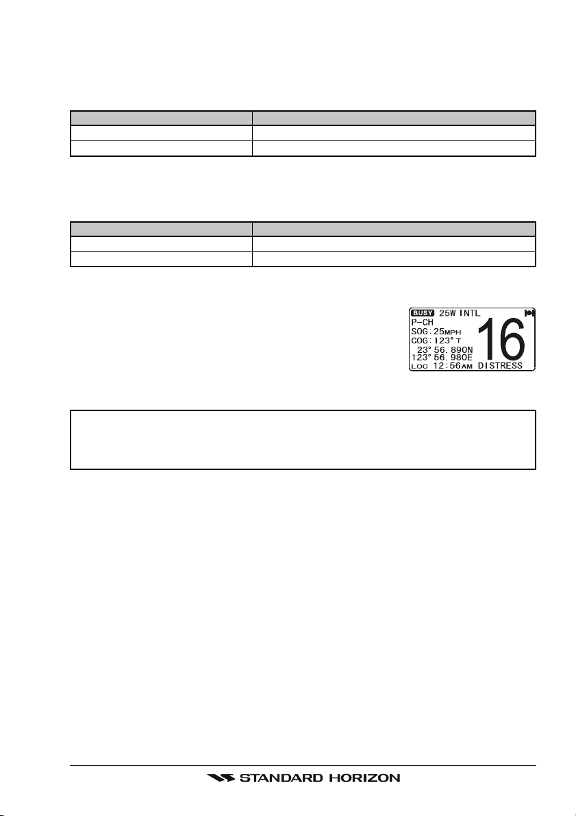
6.5 CHECKING GPS CONNECTIONS
After connections have been made between the
GX2000E/GX2100E and the GPS, a small satellite icon
will appear on the top right corner of the display and
your current location (Latitude/Longitude) is shown on
the display.
NOTE
If there is a problem with the NMEA connection between the radio and
the GPS, the GPS icon will blink continuously until the connection is
corrected.
Page 21GX2000E/GX2100E

6.6 CHANGING THE GPS TIME
From the Factory the GX2000E/GX2100E shows GPS satellite time or UTC
time when an optional GPS is connected. A time offset is needed to show the
local time in your area. The Time Offset must be changed in order for the radio
to display the current time in your area. Please see the Offset Time Table at
the bottom of this page.
1. Press and hold down the [CALL(MENU)] key
until “Setup Menu” appears, then select “GEN-
ERAL SETUP” with the CHANNEL knob.
2. Press the [SELECT] soft key, then select
“TIME OFFSET” with the CHANNEL knob.
3. Press the [SELECT] soft key, then rotate the CHAN-
NEL knob to select time offset of your location. See
illustration below to find your offset time. If “00:00”
is assigned, the time is the same as UTC (Universal
Time Coordinated or GPS Satellite Time).
4. Press the [ENT] soft key to store the time offset.
5. Press the [QUIT] soft key several times to return to radio operation.
OFFSET TIME TABLE
GX2000E/GX2100EPage 22
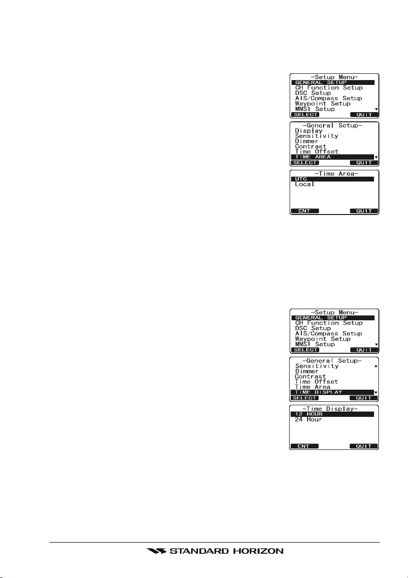
6.7 CHANGING THE TIME LOCATION
This menu selection allows the radio to show UTC time or local time with the
offset.
1. Press and hold down the [CALL(MENU)] key until
“Setup Menu” appears, then select “GENERAL SETUP”
with the CHANNEL knob.
2. Press the [SELECT] soft key, then rotate the CHAN-
NEL knob to “TIME AREA”.
3. Press the [SELECT] soft key.
4. Rotate the CHANNEL knob to select “UTC” or “LO-
CAL”.
5. Press the [ENT] soft key to store the selected setting.
6. Press the [QUIT] soft key several times to return to
radio operation.
6.8 CHANGING THE TIME FORMAT
This menu selection allows the radio to setup to show time in 12-hour or 24hour format.
1. Press and hold down the [CALL(MENU)] key until
“Setup Menu” appears, then select “GENERAL SETUP”
with the CHANNEL knob.
2. Press the [SELECT] soft key, then rotate the CHAN-
NEL knob to select “TIME DISPLAY”.
3. Press the [SELECT] soft key.
4. Rotate the CHANNEL knob to select “12 HOUR” or
“24 HOUR”.
5. Press the [ENT] soft key to store the selected setting.
6. Press the [QUIT] soft key several times to return to
radio operation.
Page 23GX2000E/GX2100E
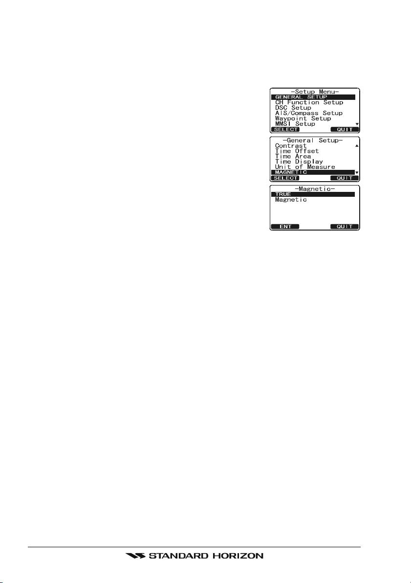
6.9 CHANGING COG TO TRUE OR MAGNETIC
Allows the GPS Course Over Ground to be selected to show in True or
Magnetic. Factory default is True however by following the steps below the
COG can be changed to Magnetic.
1. Press and hold down the [CALL(MENU)] key until
“Setup Menu” appears, then select “GENERAL SETUP”
with the CHANNEL knob.
2. Press the [SELECT] soft key, then rotate the CHAN-
NEL knob to select “MAGNETIC”.
3. Press the [SELECT] soft key.
4. Rotate the CHANNEL knob to select “MAGNETIC”
or “TRUE”.
5. Press the [ENT] soft key to store the selected setting.
6. Press the [QUIT] soft key several times to return to
radio operation.
GX2000E/GX2100EPage 24
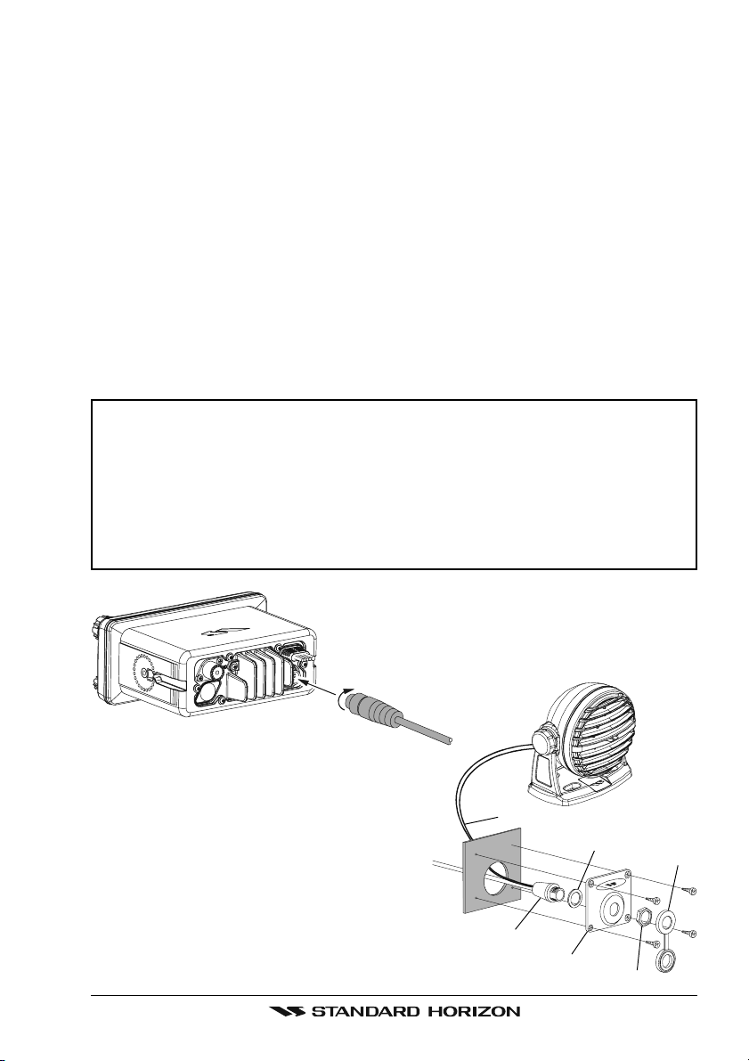
6.10 OPTIONAL CMP30 (RAM3) INSTALLATION
The GX2000E/GX2100E is capable of using a CMP30 (RAM3) Remote Station Microphone to remotely control the Radio, AIS, DSC and PA/Fog functions. In addition the GX2000E/GX2100E can operate as a full function intercom system between the RAM3 and the radio.
1. Connect the Extension Cable to the Remote Mic eight pin connector on
the rear panel, then tighten the Cable Nut (see illustration below).
2. Referring to illustration below, make a 30 mm hole in the wall, then insert
the Extension Cable into this hole. Connect the Gasket and Mount Base to
the Extension Cable Connector using the Nut.
3. Drill the four Screw holes (approx. 2 mm) on the wall, then install the Mounting Base to the wall using four screws.
4. Put the Rubber Cap on to the Nut. The installation is now complete.
NOTE
The routing cable can be cut and spliced, however care needs to be
taken when reconnecting the wires to ensure water integrity.
Before cutting the cable make sure it is not plugged into the radio. After
cutting you will notice there are the following wires:
Yellow, Green, Brown, Purple, Blue, Green, Red, Shield
The red and shield wires are wrapped in foil. Remove the foil, and
separate the Red and shield wires.
Wall
Routing Cable
External Speaker Connections
Gasket
Mounting Bracket
Cap
Nut
Page 25GX2000E/GX2100E
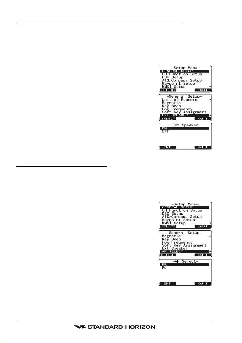
Connecting an External Speaker to the RAM3 Mic Cable
In noisy locations and optional external speaker may be connected to the white
speaker wires on the RAM3 routing cable. The RAM3 can drive the internal
speaker or the external speaker one at a time. When connecting an external
speaker, follow the procedure below to turn off the RAM3 audio and enable
the external speaker wires on the RAM3 routing cable.
1. On the RAM3 mic, press and hold the
[
CALL(MENU)] key until “Setup Menu” appears, then
select “GENERAL SETUP” with the [] / [] key.
2. Press the [ENT] key.
3. Press the [] key to until “EXT SPEAKER” is shown
and press the [SELECT] soft key.
4. Press the [] or [] key to select “OFF” (External
speaker off) or “ON” (External speaker on).
5. Press the [ENT] soft key to save the selection.
6. Press the [16/9] key to exit this mode.
External Speaker AF Selection
The “AF Select” menu allows you to set the audio output level of the RAM3
external speaker wires (on routing cable) to a fixed level regardless of the
volume level setting of the RAM3 which is useful when using the optional MLS-
310 amplified speaker with on/off volume control.
1. On the RAM3 mic, press and hold the
[
CALL(MENU)] key until “Setup Menu” appears, then
select “GENERAL SETUP” with the [] / [] key.
2. Press the [ENT] key.
3. Press the [] key to until “AF SELECT” is shown and
press the [SELECT] soft key.
4. Press the [] or [] key to select “PR” (External
Speaker Level is “Fixed”) or “PO” (External Speaker
Level is “Adjustable”).
“Fixed” use when MLS-310 is connected.
“Adjustable” use when MLS-300 or other speaker
without volume control is connected.
5. Press the [ENT] key to save the selection.
6. Press the [16/9] key to exit this mode.
GX2000E/GX2100EPage 26

MEMO
Page 27GX2000E/GX2100E

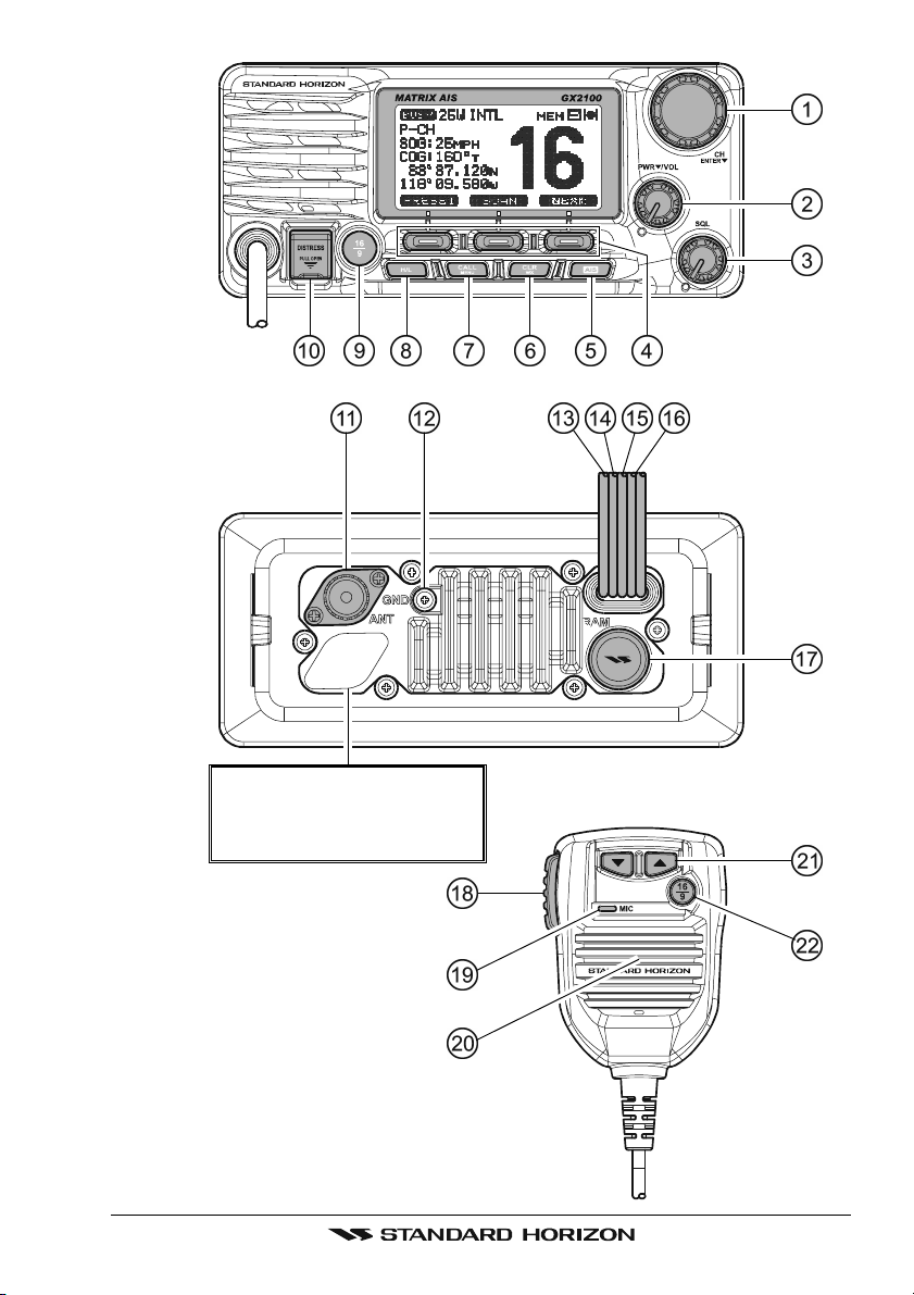
7 CONTROLS AND INDICATORS
NOTE
This section defines each control of the transceiver. See illustration at
the next page for location of controls. For detailed operating instructions
refer to chapter 8 of this manual.
7.1 CONTROLS AND CONNECTIONS
CHANNEL Knob
Rotary knob is used to select channels and to choose menu items (such
as the DSC menu, Radio Setup and DSC Setup menu). The [UP()] /
[
DOWN()] keys on the microphone can also be used to select channels
and menu items.
SECONDARY USE
Press this knob to enter a selection in the “SETUP MENU” or “DSC
MENU”.
While holding down the [SCAN] soft key and turning this knob, you can
confirm memory channels that have been programmed for scanning.
When in the PA or Fog mode, turning this knob changes the output vol-
ume of the connected horn speaker.
PWR/VOL Knob (Power Switch / Volume Control
Turns the transceiver on and off as well as adjusts the speaker volume.
To turn the transceiver on, press and hold this knob until the radio turns on.
When the power is turned on, the transceiver is set to the last selected
channel. Clockwise rotation of this knob increases the internal and speaker
microphone volume.
To turn the transceiver off, press and hold this knob until the radio turns off.
SECONDARY USE
When in PA or Fog mode, controls the listen back volume (GX2100E only).
SQL Knob (Squelch Control
Adjusting this control clockwise, sets the point at which random noise on
the channel does not activate the audio circuits but a received signal does.
This point is called the squelch threshold. Further adjustment of the squelch
control will degrade reception of wanted transmissions.
)
)
GX2000E/GX2100EPage 28
Never remove this rubber cap.
When this rubber cap is removed, the water resistance
performance is lost.
Page 29GX2000E/GX2100E

Soft Keys
The 3 soft keys functions can be customized by the Setup Menu mode
section “10.12 SOFT KEYS”. When one of the soft keys is pressed briefly,
the functions will appear above each key on the display.
[
AIS] Key
Press the [AIS] key to display the AIS (Automatic Identification System)
targets information on the display. Refer to section “13.7 AIS OPERATION”
for details.
Note: For this key to operate on the GX2000E an optional AIS receiver or
transponder and GPS must be connected to show AIS targets on the radios display. On the GX2100E a GPS must be connected to the radio to
show AIS targets on the radios display.
[
CLR(WX)] Key
Press the [CLR(WX)] key briefly to cancel a selection the “Setup Menu”
and “DSC Menu”.
[
CALL(MENU)] Key
Press the [CALL(MENU)] key to access the “DSC MENU”.
SECONDARY USE
Press and hold the [CALL(MENU)] key to access the “SETUP MENU”.
[
H/L] Key
Press the [H/L] key to toggle between 25 W (High) and 1 W (Low) power.
When the TX output power is set to “Low” while the transceiver is on channel 13 or 67, the output power will temporarily switch from “Low” to “High”
power until the PTT is released. The [H/L] key does not function on transmit inhibited and low power only channels.
SECONDARY USE
When the Normal (Radio display) is selected, push and hold this key to
show or hide SOG and COG on the display.
[
16/9] Key
Press the [16/9] key briefly to recall channel 16 from any channel location.
Press and hold the [CLR(WX)] key to recall channel 9. Pressing the [16/9
key again reverts to the previous selected working channel.
Channel 9 is used in some parts of the world as an alternative calling
channel to Channel 16.
[
DISTRESS] Key
Used to send a DSC Distress Call. To send the distress call refer to section
“9.3.1 Transmitting a DSC Distress Call.”
GX2000E/GX2100EPage 30
]
 Loading...