

Page 1
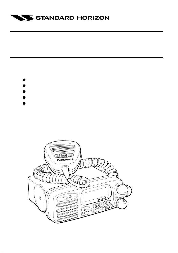
ECLIPSE + GX1250SA
25 watt VHF/FM
Marine Transceiver
Owner’s Manual
Simple Operation
Submersible Microphone
Programmable Scan & Priority Ch16 Scan
NOAA Weather Alert
Backlit LCD & Keys
STANDARD HORIZON
VOL/
PWR
Page 2

TABLE OF CONTENTS
FCC NOTICE .......................................................................................................... 1
1 GENERAL INFORMATION .............................................................................. 3
1.1 INTRODUCTION ................................................................................. 3
1.2 FCC/ INDUSTRY CANADA INFORMATION ....................................... 4
2 ACCESSORIES ............................................................................................... 5
2.1 PACKING LIST .................................................................................... 5
2.2 OPTIONS ............................................................................................. 5
3 CONTROLS AND INDICATORS ..................................................................... 6
3.1 CONTROLS AND CONNECTIONS ..................................................... 6
3.2 INDICATORS ..................................................................................... 10
4 INSTALLATION ............................................................................................. 12
4.1 FREQUENCY AND DEVIATION TESTS ........................................... 12
4.2 LOCATION......................................................................................... 12
4.3 INSTALLATION USING REGULAR MOUNTING BRACKET ............ 13
4.4 CMB16 FLUSH MOUNT INSTALLATION ......................................... 14
5 OPERATION ................................................................................................. 15
5.1 RECEPTION ...................................................................................... 15
5.2 TRANSMISSION................................................................................ 15
5.3 TRANSMIT TIME - OUT TIMER (TOT) ............................................. 16
5.4 SIMPLEX/DUPLEX CHANNEL USE ................................................. 16
5.5 USA, CANADA, AND INTERNATIONAL MODE ............................... 16
5.6 NOAA WEATHER CHANNELS ......................................................... 17
5.7 NOAA WEATHER ALERT ................................................................. 17
5.8 MEMORY SCANNING ....................................................................... 18
5.9 PRIORITY SCANNING (PRI-SCAN) ................................................. 18
6 MAINTENANCE ............................................................................................. 19
6.1 REPLACEMENT PARTS ...................................................................... 19
6.2 TROUBLESHOOTING CHART ............................................................ 20
7 SPECIFICATIONS ......................................................................................... 21
7.1 GENERAL .......................................................................................... 21
7.2 TRANSMITTER ................................................................................. 21
7.3 RECEIVER......................................................................................... 21
Page 3

FCC NOTICE
IMPORTANT NOTICE
The following device operating configurations must be satisfied:
— This radio is restricted to occupational use, work related
operations only where the radio operator must have the
knowledge to control its RF exposure conditions.
— The radio must be used with a maximum operating duty cycle not
exceeding 50%, in typical Push-to-Talk configurations.
— When transmitting, hold the radio in a vertical position with its
microphone 1 to 2 inches (2.5 to 5 cm) away from your mouth and
keep the antenna at least 1 inch (2.5 cm) away from your head
and body.
SAFETY / WARNING INFORMATION
WARNING - DO NOT operate the ECLIPSE+ radio when someone
(bystanders) outside the vehicle is within (to calculate) 3 feet (1 meter)
of the antenna.
ANTENNA INSTALLATION:
For rear deck trunk installation, the antenna must be located at least 3
feet (1 m) away from rear seat passengers in order to comply with the
FCC RF exposure requirements.
For roof top installation, the antenna must be placed in the center of
the roof.
GX1250SA Owner’s Manual page 1
Page 4

NOTICE
Unauthorized changes or modifications to this equipment may void
compliance with FCC Rules. Any change or modification must be
approved in writing by STANDARD HORIZON, a division of VERTEX
STANDARD.
NOTICE
This equipment has been tested and found to comply with the limits for
a Class B digital device, pursuant to Part 15 of the FCC Rules. These
limits are designed to provide reasonable protection against harmful
interference in a residential installation. This equipment generates,
uses and can radiate radio frequency energy and, if not installed and
used in accordance with the instructions, may cause harmful
interference to radio communications. However, there is no guarantee
that interference will not occur in a particular installation. If this
equipment does cause harmful interference to radio or television
reception, which can be determined by turning the equipment off and
on, the user is encouraged to try to correct the interference by one or
more of the following measures:
— Reorient or relocate the receiving antenna.
— Increase the separation between the equipment and receiver.
— Connect the equipment into an outlet on a circuit different from
that to which the receiver is connected.
— Consult the dealer or an experienced radio/TV technician for
help.
page 2 Owner’s Manual GX1250SA
Page 5

1 GENERAL INFORMATION
1.1 INTRODUCTION
Congratulations on your purchase of the ECLIPSE+! Whether this is your
first marine VHF transceiver, or if you have other STANDARD HORIZON
equipment, The STANDARD HORIZON organization is committed to
ensuring your enjoyment of this high-performance transceiver, which
should provide you with many years of satisfying communications even in
the harshest of environments. STANDARD HORIZON technical support
personnel stand behind every product we sell, and we invite you to contact
us should you require technical advice or assistance.
We appreciate your purchase of the ECLIPSE+, and encourage you to
read this manual thoroughly, so as to learn and understand the capabilities
of the ECLIPSE+ fully.
The STANDARD HORIZON (a division of VERTEX STANDARD)
ECLIPSE+ is a VHF/FM transceiver designed for use in the frequency
range of 156.025 to 163.275 MHz. The ECLIPSE+ requires 13.8V ± 20 %
for operation and has a switchable RF output power of 1 watt or 25 watts.
The transceiver operates on all currently-allocated marine channels which
are switchable for use with either USA, International, or Canadian
regulations. It has an emergency channel 16 which can be immediately
selected from any channel by pressing the red 16/9 key. NOAA Weather
channels can also be accessed immediately by pressing the WX key with
channel selection.
Other features of the transceiver include: scanning, priority scanning,
NOAA Weather Alert and submersible microphne.
GX1250SA Owner’s Manual page 3
Page 6

1.2 FCC/ INDUSTRY CANADA INFORMATION
The following data pertaining to the transceiver is necessary to fill out the
license application.
Type Acceptance ................................................................... FCC Part 80
Output Power .......................................... 1 Watt (low) and 25 Watts (high)
Emission...................................................................................... 16K0F3E
Frequency Range ............................................... 156.025 to 163.275 MHz
FCC Type Number ...................................................................... APV0493
Industry Canada Type Approval ..................................... 363822161LVCA
Additional FCC and Industry Canada data, including licensing
requirements, are contained in the companion document titled
OWNER’S MANUAL SUPPLEMENT. The document also contains
charts for VHF channel assignments, transceiver procedures,
maintenance, factory service information, and warranty data.
page 4 Owner’s Manual GX1250SA
Page 7

2 ACCESSORIES
2.1 PACKING LIST
When the package containing the transceiver is first opened, please check
it for the following contents:
• GX1250SA ECLIPSE+ Transceiver (White/Black)
• CMP349WR/CMP349BR (White/Black Microphone attached to the
transceiver) and hanger kit
• Mounting Bracket and attaching hardware
• Owner’s Manual
• Owner’s Manual Supplement
• Power Cord
2.2 OPTIONS
CMB16 ...................................................................... Flush-Mount Bracket
101S ...................................................................... Mini Extension Speaker
201S ............................................................................. Extension Speaker
201SZ...................................................... Flush Mount Extension Speaker
GX1250SA Owner’s Manual page 5
Page 8

3 CONTROLS AND INDICATORS
NOTE
This section defines each control of the transceiver. See Figure 1 for
location of controls. For detailed operating instructions refer to chapter
4 of this manual.
3.1 CONTROLS AND CONNECTIONS
q POWER SWITCH/VOLUME CONTROL
Turns the transceiver on and off as well as adjusts the audio volume.
When the power is turned on, the transceiver is set to the last selected
channel.
Secondary Use
When the transceiver is turned on while the SCAN and WX keys are held
down, the internal microprocessor is reset. This clears the memory and all
user-programmed settings, such as scan memory assignments. This
condition is known as the default condition, the same as when shipped
from the factory. For a list of these defaults, see the section on Resetting
the Transceiver’s Microprocessor.
w SQUELCH CONTROL (SQL)
Sets the point at which random noise on the channel does not activate
the audio circuits but a received signal does. This point is called the
squelch threshold. Further adjustment of the squelch control will
degrade reception of wanted transmissions.
e KEY PAD
16/9 Key
Immediately recalls channel 16 from any channel location. Holding
down this key recalls channel 9.
Secondary use
Please see secondary use for the WX key.
page 6 Owner’s Manual GX1250SA
Page 9

STANDARD HORIZON
ECLIPSE +
SCAN
/
L
H
16 / 9
WX
VOL/
PWR
U.I.CMEM
SQL
q
r
y
u
i
16/9
o
Figure 1. Controls and Connectors
w
e
t
!0
GX1250SA Owner’s Manual page 7
Page 10

WX Key
Immediately recalls the previously selected NOAA weather channel
from any channel location.
Secondary use
1. Holding down the 16/9 key while pressing the WX key changes the
mode from USA to International or Canadian.
2. Holding down the WX and SCAN key while turning the power on resets
the microprocessor and erases scan channels from memory. This clears
the memory and establishes the factory-set defaults. For a list of these
defaults, see the section on Resetting the Transceiver’s Microprocessor.
SCAN Key
1. Starts and stops scanning of programmed channels.
2. Memorizes the selected channel into the transceivers scan memory
for scanning. When pressed and held down again it, DELETES the
channel from the scan memory.
Secondary use
1. If held while the UP or DOWN key is pressed, the transceiver will
show the channels in scan memory. This function will not work if the
unit is scanning.
H/L Key
Toggles between high and low power. When the H/L key is pressed
while the transceiver is on channel 13 or 67, the power will temporarily
switch from LO to HI power until the PTT is pressed. The H/L key does
not function on transmit inhibited and low power only channels.
UP
and DOWN Keys
The UP and DOWN keys are used to select channels.
r EXTERNAL SPEAKER JACK
Connects an optional external speaker to the transceiver. Use a
speaker with an impedance of 4 or 8 ohms, with an RCA phono plug.
t ANTENNA JACK
Connects an antenna to the transceiver. Use a marine VHF antenna
with an impedance of 50 ohms.
page 8 Owner’s Manual GX1250SA
Page 11

y DC INPUT CABLE
Connects the transceiver to a DC power supply of 13.8V ± 20 %.
u PTT (Push-To-Talk) SWITCH
Keys the transmitter when the transceiver is in radio mode. If the
transceiver is in the intercom operation mode, it activates the
microphone for the intercom.
i Submersible MIC
This microphone's water-resistant is equivalent to JIS Class 7th.
o UP and DOWN KEYS
The UP and DOWN on the mic function the same as the The UP
and DOWN keys on the front panel of the transceiver.
!0 16/9 Key
Pressing the 16/9 key Immediately recalls channel 16 from any
location. Press and hold the 16/9 key to recall channel 9.
GX1250SA Owner’s Manual page 9
Page 12

3.2 INDICATORS
U
TX
C
I
HI
WX
LO
A
Figure 2. Indicators
The LCD on the transceiver has several symbols and indicators that
should be understood by the user before operating the unit. Figure 2
shows all of these symbols and indicators, although it is not possible to
see them at the same time.
U/I/C Indicator
Indicates the mode of operation (USA, International or Canadian) for a
particular channel.
WX Indicator
Indicates a weather channel.
TX Indicator
Transmission indicator. The TX indicator appears when th PTT switch
is pressed and it is O.K. to transmit.
MEM Indicator
Indicates the channel is memorized in the transceiver’s memory.
A Indicator
Indicates a simplex channel in USA or Canadian mode whose
counterpart in the International mode is a duplex channel.
page 10 Owner’s Manual GX1250SA
Page 13

7-SEGMENT Display
Displays the channel number in use.
HI/LO Indicator
Indicates the power setting. “HI” 25 watts and “LO” 1 watt. This display
is blank if a transmission-inhibited channel is selected.
GX1250SA Owner’s Manual page 11
Page 14

4 INSTALLATION
4.1 FREQUENCY AND DEVIATION TESTS
FCC regulations require that the transceiver’s deviation and frequency be
tested before initial installation or operation. This test should be performed
by a Certified Marine Technician.
4.2 LOCATION
1. The transceiver can be mounted at any angle. Choose a mounting
location that:
• is far enough from any compass to avoid erroneous compass
reading due to the speaker magnet
• provides protection from sea spray and rain
• provides accessibility to the front panel controls
• allows connection to a power source and an antenna
• has nearby space for installation of a microphone hanger
2. Install the unit in accordance with paragraph 4.3 or 4.4.
In each appears an instruction to connect the power supply and
antenna. Where that appears, the following three steps should be
performed:
/
L
O
V
R
W
P
Figure 3. General Installation
page 12 Owner’s Manual GX1250SA
Page 15

a. At the rear of the transceiver, connect the antenna cable to the
antenna jack. The antenna must have a PL259 connector. RG8 or
RG213 coaxial cable must be used if the antenna is 25 feet or
more from the transceiver. RG58 cable can be used for distances
less than 25 feet.
b. Connect the red power cord to a 13.8 VDC ± 20 % power source.
Connect the black power cord to negative ground. See Figure 3 for
this step .
c. It is advisable to have a Certified Marine Technician check the
power output and the standing wave ratio of the antenna after
installation.
4.3 INSTALLATION USING REGULAR MOUNTING BRACKET
1. Mount the bracket using the washers, nuts, and long hex head bolts.
2. Thread the mylar washers onto the mounting bracket knobs.
3. Position the transceiver within the bracket arms, matching the
transceiver notches to obtain the desired positioning.
4. Secure the transceiver to the brackets with the mounting knobs (see
Figure 4).
5. Connect the antenna and power cables (and optional speaker) to the
transceiver.
Figure 4. Regular Mounting Bracket
GX1250SA Owner’s Manual page 13
Page 16

4.4 CMB16 FLUSH MOUNT INSTALLATION
1. Make a rectangular template for the flush mount measuring 2
inches (50 mm) H x 5 3/8" inches (135 mm) W.
2. Use the template to mark the location where the rectangular hole is
to be cut. Confirm the space behind the dash or panel is deep
enough to accommodate the transceiver (at least 6 inches deep).
There should be at least 1/2 inch between the transceiver’s heatsink
and any wiring, cables or structures.
3. Cut out the rectangular hole and insert the transceiver.
4. Fasten the brackets to the sides of the transceiver with the lock
washer nut combination, so that the mounting screw base faces the
mounting surface (see Figure 5).
5. Turn the adjusting screw to adjust the tension so that the
transceiver is tight against the mounting surface.
Bracket
Adjusting screw
Lock-washer nut combination
Figure 5. CMB16 Flush Mount Installation
page 14 Owner’s Manual GX1250SA
Page 17

5 OPERATION
5.1 RECEPTION
1. After the transceiver has been installed, ensure that the power
supply and antenna are properly connected.
2. Turn the VOL/PWR knob until the transceiver turns on.
3. Turn the SQL knob fully counterclockwise. This state is known as
“squelch off”.
4. Turn up the volume until noise or audio from the speaker is at a
comfortable level.
5. Turn the SQL knob clockwise until the random noise disappears.
This state is known as the “squelch threshold.”
6. Press the UP
to the channel chart in the OWNER’S MANUAL SUPPLEMENT for
available channels.
7. When a message is received, adjust the volume to the desired
listening level.
5.2 TRANSMISSION
1. Perform steps 1 through 6 of RECEPTION.
2. Before transmitting, monitor the channel to ensure it is clear. THIS
IS AN FCC REQUIREMENT!
3. Press the PTT (push-to-talk) switch. The TX indicator on the LCD is
displayed.
4. Speak slowly and clearly into the microphone.
5. When the transmission is finished, release the PTT switch.
6. Refer to the OWNER’S MANUAL SUPPLEMENT for standard
transceiver operating procedures.
or DOWN key to select the desired channel. Refer
NOTE
This microphone should be positioned within 1 inch (2 cm) from the
mouth for optimum performance.
GX1250SA Owner’s Manual page 15
Page 18

5.3 TRANSMIT TIME - OUT TIMER (TOT)
When the PTT switch on the microphone is held down, transmit time is
limited to 5 minutes. This prevents unintentional transmissions. About 10
seconds before automatic transmitter shutdown, a warning beep will be
heard from the speaker(s). The transceiver will automatically go to receive
mode, even if the PTT switch is continually held down. Before transmitting
again, the PTT switch must first be released and then pressed again.
5.4 SIMPLEX/DUPLEX CHANNEL USE
Refer to the OWNER’S MANUAL SUPPLEMENT for instructions on use of
simplex and duplex channels.
NOTE
All channels are factory-programmed in accordance with FCC (USA),
Industry Canada (Canada), and International regulations. Mode of
operation cannot be altered from simplex to duplex or vice-versa.
5.5 USA, CANADA, AND INTERNATIONAL MODE
1. To change the modes, hold the 16/9 key and press the WX key. The
mode changes from USA to International to Canadian with each
press of the WX key.
2. USA will be displayed on the LCD for USA mode, INTL will be
displayed for International mode, and CAN will be displayed for
Canadian mode.
3. Refer to the OWNERS MANUAL SUPPLEMENT for allocated
channels in each mode.
page 16 Owner’s Manual GX1250SA
Page 19

5.6 NOAA WEATHER CHANNELS
1. To receive a NOAA weather channel, press the WX key from any
channel. The transceiver will go to the last selected weather
channel.
2. Press the UP
channel.
3. To exit from the NOAA weather channels, press the WX key. The
transceiver returns to the channel it was on prior to a weather
channel.
or DOWN key to select a different NOAA weather
5.7 NOAA WEATHER ALERT
In the event of extreme weather disturbances, such as storms and
hurricanes, the NOAA (National Oceanic and Atmospheric Administration)
sends a weather alert accompanied by a 1050 Hz tone and subsequent
weather report on one of the NOAA weather channels. The transceiver is
capable of receiving this alert if the following is performed:
1. Program NOAA weather channels into the transceiver’s memory for
scanning. Follow the same procedure as for regular channels under
Section 5.8.
2. Press the SCAN key once to start memory scanning or hold down
the SCAN key during memory scanning to start priority scanning.
3. The programmed NOAA weather channels will be scanned along
with the regular-programmed channels. However, scanning will not
stop on a normal weather broadcast unless a NOAA alert is
received.
4. When an alert is received on a NOAA weather channel, scanning
will stop and the transceiver will emit a loud beep to alert the user of
a NOAA broadcast.
5. Press the WX key to stop the alert tone and receive the weather
report.
NOTE
If the WX key is not pressed the alert tone will be emitted for 5 minutes
and then the weather report will be received.
GX1250SA Owner’s Manual page 17
Page 20

5.8 MEMORY SCANNING
1. Adjust the SQL knob until background noise disappears.
2. Select a desired channel to be scanned using the UP or DOWN
key. Press and hold down the SCAN key until MEM appears on the
LCD which programs the channel into the transceivers memory.
3. Repeat step 2 for all the desired channels to be scanned.
4. To DELETE a channel from the transceiver’s memory, select a
channel to be erased with the UP
down the SCAN key until MEM disappears on the LCD.
5. To start scanning, press the SCAN key. Scanning will proceed from
the lowest to the highest programmed channel number and will stop
on a channel when a transmission is received.
6. The received channel number will blink during busy stop.
7. To stop scanning, press the SCAN, 16/9, WX, or PTT key.
or DOWN key. Press and hold
5.9 PRIORITY SCANNING (PRI-SCAN)
1. To select priority scanning, hold down the SCAN key and turn the
transceiver on.
2. Press SCAN key again. Scanning will proceed between the
memorized channels (MEM CH) and the priority channel (P-CH).
The priority channel will be scanned after each programmed
channel.
P-CH.MEM CH1 MEM CH2 P-CH.
(The priority channel (P-CH) is channel 16.)
3. To stop scanning, press the SCAN, 16/9, WX, or PTT key.
page 18 Owner’s Manual GX1250SA
Page 21

6 MAINTENANCE
The inherent quality of the solid-state components used in this transceiver
will provide many years of continuous use. Taking the following
precautions will prevent damage to the transceiver.
* Never key the microphone unless an antenna or suitable dummy load is
connected to the transceiver.
* Ensure that the supply voltage to the transceiver does not exceed 16
VDC or fall below 11 VDC.
In the unlikely event of serious problems, please contact your STANDARD
HORIZON Dealer or our repair facility. Address and phone numbers for this
facility, as well as warranty information, are contained in your Owner’s
Manual Supplement.
6.1 REPLACEMENT PARTS
Occasionally an owner needs a replacement mounting bracket or knob.
These can be ordered from our Parts Department by writing or calling:
STANDARD HORIZON, a division of VERTEX STANDARD.
17210 Edwards Rd., Cerritos, CA 90703, U.S.A.
(562)404-2700
Commonly requested parts, and their part numbers are listed below.
Microphone, White (CMP349WR) .............................. MP51000460
Microphone, Black (CMP349BR) ............................... MP51000470
Mounting Bracket, White ............................................ 457X160010
Mounting Bracket, Black ............................................ 457X160110
Mounting Bracket Knob, White .................................. 444X154030
Mounting Bracket Knob, Black ................................... 444X154130
Volume Control Knob ................................................. 444X154500
Squelch Control Knob ................................................ 444X154500
Power Cord ................................................................ ZC01300010
Mic Hanger, White...................................................... 277X155020
Mic Hanger, Black ...................................................... 277X155120
GX1250SA Owner’s Manual page 19
Page 22

6.2 TROUBLESHOOTING CHART
TROUBLESHOOTING CHART
SYMPTOM
Transceiver fails to
power up.
PROBABLE
CAUSE
No DC voltage to the
transceiver, or blown
fuse.
REMEDY
Check the power cable for DC voltage,
or replace the fuse (6A 250V).
Transceiver blows fuse
when connected to
power supply.
Popping or whining noise
from the speaker while
engine runs.
External speaker plug
does not fit into jack.
Internal speaker turns off
when external speaker is
plugged in.
Transceiver transmits but
does not receive.
Transceiver transmits on
low power only.
Reversed power wires.
Engine noise
.
Incorrect plug on
speaker cable.
No problem.
Channel mode.
Antenna
Make sure the red wire is connected to
the positive battery post and the black
wire is connected to the negative. If
the fuse still blows, contact your
STANDARD HORIZON Dealer.
Reroute the DC power cables away
from the engine. Add noise
suppressor on power cable. Change
to resistive spark plug wires and/or
add an alternator whine filter.
The external speaker jack accepts
only RCA phono plugs.
Normal transceiver operation causes
internal speaker cut-off when external
speaker is plugged in.
The transceiver may be tuned to a
duplex channel meant for ship-to-shore
radiotelephone communications.
Have antenna checked or test the
transceiver with another antenna. If
problem persists, contact your
STANDARD HORIZON Dealer.
page 20 Owner’s Manual GX1250SA
Page 23

7 SPECIFICATIONS
Performance specifications are nominal, unless otherwise indicated, and
are subject to change without notice.
7.1 GENERAL
Channels ...........................................All USA, International and Canadian
Input Voltage ....................................................................13.8 VDC ± 20%
Current Drain
Standby ........................................................................................ 0.5A
Receive ........................................................................................ 1.5A
Transmit .................................................................. 6A (Hi); 1.7A (Lo)
Dimensions ............................................................. 2-1/2" H x 6" W x 6" D
Flush-Mount Dimensions .................................. 2" H x 5-3/8" W x 5-1/4" D
Weight .............................................................................. 1.9 Lb. (0.86 kg)
7.2 TRANSMITTER
Frequency Range ............................................... 156.025 to 157.425 MHz
RF Output.................................................................... 25 W (Hi); 1 W (Lo)
Conducted Spurious Emissions .............................. 65 dB (Hi); 50 dB (Lo)
Audio Response ................... within + 2/–8 of a 6 dB/octave pre-emphasis
Audio Distortion .................................................................................... 5 %
Modulation .................................................................................. 16K0F3E
Frequency Stability (-20° to +50°C) ......................................... ± 0.0005%
FM Hum and Noise ................................................................... 40 dB min.
(65 H x 150 W x 150 D mm)
(50 H x 135 W x 133 D mm)
characteristic at 300 to 3000 Hz
7.3 RECEIVER
Frequency Range ............................................... 156.050 to 163.275 MHz
Sensitivity:
20 dB Quieting .......................................................................... 0.4 µV
12 dB SINAD ........................................................................... 0.35 µV
Squelch Sensitivity (Threshold) ....................................................... 0.2 µV
Modulation Acceptance Bandwidth ............................................. ± 4.5 kHz
Selectivity:
Spurious and Image Rejection ................................................... 70 dB
Intermodulation and Rejection at 12 dB SINAD ......................... 65 dB
Audio Output ........................................................................................ 4 W
Audio Response .......................................... within + 2/–8 of a 6 dB/octave
Frequency Stability (-20° to +50°C) ........................................... ± 0.001 %
Channel Spacing ............................................................................. 25 kHz
GX1250SA Owner’s Manual page 21
de-emphasis characteristic at 300 to 3000 Hz
Page 24

Marine Division of Vertex Standard
US Headquarters
17210 Edwards Rd., Cerritos, CA 90703
Phone 562/404-2700
Fax 800/552/6813
Email marinetech@vxstd.com
www.vxstd.com
Printed in China
05/2001 457X851010
 Loading...