

Standard Horizon Explorer GPS GX1700 Owner's Manual

EXPLORER GPS
GX1700
25 Watt VHF/FM
Marine Transceiver
Owner's Manual
Integrated 12 Channel WAAS GPS receiver
GPS antenna built-in to the front panel allows reception when bracket or ush
mounted
Ultra thin and compact rear case design (3.5” depth)
Meets ITU-R M493-13 Class D DSC (Digital Selective Calling)
Navigation to a DSC Distress Call with compass page
DSC test call and Auto DSC channel change selection
Automatically poll the GPS position of up to 4 ships using DSC
Enter, Save, and Navigation to a waypoint with Compass page
Navigation (LAT/LON, SOG, and COG) information shown on display
Submersible JIS-8 1.5M (4.92Ft) for 30 minutes
Noise canceling microphone with channel selection, 16/9 and H/L keys
NOAA weather channel selection with alert
Programmable Scan, Priority Scan, and Dual Watch
Preset key stores up to 10 favorite channels, with scan function
Oversized dot matrix display with customizable channel names and GPS Com-
pass display
NMEA Input and Output of GPS information to other NMEA compatible devices
Programmable soft keys
Capable of connecting to a Second Station Remote-Access Microphone
CMP30
Die-cast chassis
Dimensions: 5.9” W x 3.4” H x 3.6” D
Flush mount cutout: 5.4” W x 2.8” H x 2.6” D
3 Year Waterproof Warranty
Page 1GX1700

TABLE OF CONTENTS
Quick Reference Guide ..............................................................................4
1 GENERAL INFORMATION ...................................................................5
2 PACKING LIST .....................................................................................5
3 OPTIONS ...............................................................................................5
4 ON-LINE WARRANTY REGISTRATION (in USA or Canada only) ...6
5 GETTING STARTED .............................................................................7
5.1 PROHIBITEDCOMMUNICATIONS............................................7
5.2 ABOUTVHFRADIO..................................................................7
5.3 SELECTINGANANTENNA.......................................................7
5.3.1 CoaxialCable.................................................................8
5.4 EMERGENCY(CHANNEL16USE)............................................8
5.5 CALLINGANOTHERVESSEL(CHANNEL16OR9)................9
5.6 OPERATINGONCHANNELS13AND67............................10
5.7 AUTOMATEDRADIOCHECKSERVICE...............................10
6 INSTALLATION....................................................................................12
6.1 SAFETY/WARNINGINFORMATION......................................12
6.2 LOCATION.................................................................................12
6.3 MOUNTINGTHERADIO.........................................................12
6.3.1 SuppliedMountingBracket..........................................12
6.3.2 OptionalMMB-97FlushMountBracket.....................13
6.4 ELECTRICALCONNECTIONS................................................14
6.5 ACCESSORYCABLE...............................................................15
6.5.1 InternalGPS(DSCOutputtoaChartPlotter)........15
6.5.2 ExternalGPSorChartPlotter(forGPS)..................15
6.5.2.1GPSInput-
StandardHorizonGPSAntenna.....................15
6.5.2.2GPSInputandDSCOutput
GPSChartPlotter(RS422Connection).........16
6.5.2.3StandardHorizonChartPlotter
6.6 CHECKINGGPSSTATUS.......................................................17
6.7 CHANGINGTHEGPSTIME..................................................18
6.8 CHANGINGTHETIMEAREA.................................................19
6.9 CHANGINGTHETIMEDISPLAY...........................................19
6.10 CHANGINGCOGTOTRUEORMAGNETIC......................20
6.11 OPTIONALRAM3(CMP30)INSTALLATION.........................20
7 CONTROLS AND INDICATORS .......................................................24
7.1 FRONTPANEL.........................................................................24
7.2 REARPANEL............................................................................26
7.3 MICROPHONE..........................................................................27
8 BASIC OPERATION ........................................................................... 28
8.1 RECEPTION..............................................................................28
8.2 TRANSMISSION........................................................................28
8.3 TRANSMITTIME-OUTTIMER(TOT)...................................... 28
8.4 SIMPLEX/DUPLEXCHANNELUSE......................................29
8.5 DISPLAYTYPE.........................................................................29
8.6 USA,CANADA,ANDINTERNATIONALMODE.......................30
8.7 NOAAWEATHERCHANNELS................................................30
8.8 DUALWATCH(TOCHANNEL16)............................................31
8.9 SCANNING................................................................................32
orOtherChartPlotter(RS232Connection).16
6.11.1 ConnectinganExternalSpeaker
totheRAM3MicCable..............................................22
6.11.2 ExternalSpeakerAFSelection...................................22
8.7.1 NOAAWeatherAlert....................................................30
8.7.2 NOAAWeatherTesting................................................31
8.9.1 ScanTypeSelection....................................................32
8.9.2 ScanandP-ScanMemoryProgramming..................32
8.9.3 MemoryScanning(M-SCAN
8.9.4 PriorityScanning(P-SCAN
).......................................33
)..........................................33
8.10 PRESETCHANNELS(0~9):INSTANTACCESS................34
8.10.1 PresetChannelProgramming.....................................34
8.10.2 Operation.......................................................................34
8.10.3 DeletingaPresetChannel...........................................34
8.11 INTERCOMOPERATION.........................................................35
8.11.1 Communication..............................................................35
8.11.2 Calling............................................................................35
9 DIGITAL SELECTIVE CALLING .......................................................36
9.1 GENERAL.................................................................................. 36
9.2 MARITIMEMOBILESERVICEIDENTITY(MMSI).................36
9.2.1 WhatisanMMSI?......................................................36
9.2.2 ProgrammingtheMMSI...............................................37
9.3 DSCDISTRESSALERT..........................................................38
9.3.1 TransmittingaDSCDistressAlert.............................38
9.3.1.1TransmittingaDSCDistressAlert
withNatureofDistress...................................39
9.3.1.2TransmittingaDSCDistressAlert
byManuallyEnteringaPosition....................40
9.3.1.3PausingaDSCDistressCall........................41
9.3.1.4CancelaDSCDistressCall..........................41
9.3.2 ReceivingaDSCDistressCall..................................41
a.ACCEPT...................................................................41
b.PAUSE......................................................................41
9.4 ALLSHIPSCALL..................................................................... 43
9.5 INDIVIDUALCALL....................................................................45
9.6 DSCLOGOPERATION...........................................................51
9.7 GROUPCALL........................................................................... 54
c.QUIT.........................................................................41
9.4.1 TransmittinganAllShipsCall....................................43
9.4.2 ReceivinganAllShipsCall........................................44
9.5.1 Individual/PositionCallDirectorySetup......................45
9.5.2 IndividualReplySetup.................................................46
9.5.3 IndividualAcknowledgmentSetup...............................47
9.5.4 Individual/GroupCallRingerSetup..........................47
9.5.5 TransmittinganIndividualCall....................................48
9.5.5.1IndividualCall
usingtheIndividualDirectory.........................48
9.5.5.2IndividualCall
byManuallyEnteringaMMSI.......................49
9.5.6 ReceivinganIndividualCall.......................................50
9.6.1 ReviewingandResending
aTransmittedLoggedCall..........................................51
9.6.2 ReviewingaDSCDistressLoggedCall...................51
9.6.3 ReviewingaOtherLoggedCalls...............................52
9.6.4 DeletingaCallfromthe“DSCLOG”Directory.......52
9.7.1 GroupCallSetup.........................................................54
9.7.2 TransmittingaGroupCall...........................................55
9.7.2.1GroupCall
usingtheIndividualDirectory.........................55
9.7.2.2GroupCall
byManuallyEnteringaMMSI.......................56
9.7.3 ReceivingaGroupCall...............................................57
GX1700Page 2

TABLE OF CONTENTS
9.8 POSITIONREQUEST..............................................................58
9.8.1 PositionReplySetup...................................................58
9.8.2 PositionRequestRingerSetup..................................59
9.8.3 TransmittingaPositionRequest
toAnotherVessel.........................................................59
9.8.3.1PositionRequest
usingtheIndividualDirectory.........................59
9.8.3.2PositionRequest
byManuallyEnteringaMMSI.......................60
9.8.4 ReceivingaPositionRequest.....................................61
9.9 POSITIONREPORT.................................................................62
9.9.1 PositionReportRingerSetup.....................................62
9.9.2 TransmittingaDSCPositionReportCall..................62
9.9.2.1DSCPositionReportCall
usingtheIndividualDirectory.........................62
9.9.2.2DSCPositionReportCall
byManuallyEnteringaMMSI.......................63
9.9.3 ReceivingaDSCPositionReportCall......................64
9.9.4 NavigatingtoaPositionReport.................................64
9.9.5 StopNavigatingtoPositionReport............................64
9.9.6 SavingaPositionReportCallasaWaypoint.........65
9.9.7 NavigatingtoaSavedWaypoint................................65
9.9.8 StopNavigatingtoaSavedWaypoint......................65
9.10 MANUALINPUTTINGAGPSPOSITION(LAT/LON)...........66
9.11 AUTOPOSPOLLING..............................................................67
9.11.1 PollingTimeIntervalSetup.........................................67
9.11.2 SelectingStations
tobeAutomaticallyPolled(tracked)..........................67
9.11.3 Enable/DisableAutoPOSPolling...............................68
9.12 DSCTEST................................................................................69
9.12.1 ProgrammingMMSIintoIndividualDirectory............69
9.12.2 DSCTestCallbyusingIndividualDirectory............69
9.12.3 DSCTestCallbyManuallyEnteringMMSI.............70
10 GENERAL SETUP .............................................................................71
10.1 DISPLAY.................................................................................... 71
10.2 DIMMERADJUSTING..............................................................72
10.3 CONTRAST..............................................................................72
10.4 UNITOFMEASURE................................................................73
10.5 KEYBEEP................................................................................74
10.6 STATIONNAME.......................................................................75
10.7 SOFTKEYS..............................................................................76
10.7.1 SelectingtheNumberofSoftKeys...........................76
10.7.2 AssigningSoftKeys.....................................................76
10.7.3 SelectingHowLongtheSoftKeysareShown........77
11 CHANNEL FUNCTION SETUP .........................................................78
11.1 CHANNELGROUP
(USA,CANADAorINTERNATIONALBANDSELECTION).78
11.2 SCANMEMORYCHANNEL....................................................78
11.3 SCANTYPE..............................................................................79
11.4 SCANRESUME........................................................................79
11.5 PRIORITYCHANNEL...............................................................80
11.6 WEATHERALERT....................................................................80
11.7 CHANNELNAME.....................................................................81
12 DSC SETUP ........................................................................................82
12.1 INDIVIDUALDIRECTORY........................................................82
12.2 INDIVIDUALREPLY.................................................................82
12.3 INDIVIDUALACKNOWLEDGMENT.........................................82
12.4 INDIVIDUALRINGER...............................................................82
12.5 GROUPDIRECTORY...............................................................82
12.6 POSITIONREPLY....................................................................83
12.7 AUTOPOSITIONINTERVAL...................................................83
12.8 DSCBEEP................................................................................83
12.9 AUTOCHANNELSWITCHTIME...........................................84
13 WAYPOINTS ........................................................................................ 85
13.1 MARKINGAPOSITION...........................................................85
13.2 ADDINGAWAYPOINT............................................................86
13.3 EDITINGAWAYPOINT............................................................87
13.4 DELETINGAWAYPOINT........................................................88
13.5 SAVINGADSCPOSITIONCALLASAWAYPOINT...........88
13.6 NAVIGATINGTOASAVEDWAYPOINT................................89
13.7 STOPNAVIGATINGTOAWAYPOINT..................................89
13.8 WAYPOINTSETUP..................................................................90
13.8.1 WaypointRangeSelection..........................................90
13.8.2 DirectionSelection........................................................90
14 GPS SETUP ........................................................................................92
14.1 UNITPOWER...........................................................................92
14.2 COORDINATESYSTEM..........................................................92
14.3 PINNING....................................................................................93
14.4 TIMEOFFSET..........................................................................93
14.5 TIMEAREA...............................................................................93
14.6 TIMEDISPLAY..........................................................................93
14.7 MAGNETIC................................................................................93
14.8 POSITIONINPUT.....................................................................94
14.9 GPSSELECTION......................................................................94
14.10SBAS(WAAS,EGNOS,MSAS)..............................................95
14.11NMEAOUTPUT........................................................................95
15 RAM3 (CMP30) REMOTE MIC OPERATION ..................................96
15.1 REMOTEMICCONTROLS....................................................96
15.2 ASSIGNINGSOFTKEYS.......................................................98
16 MAINTENANCE .................................................................................100
16.1 REPLACEMENTPARTS........................................................100
16.2 FACTORYSERVICE..............................................................100
16.3 TROUBLESHOOTINGCHART...............................................101
17 CHANNEL ASSIGNMENTS ..............................................................102
18 WARRANTY .......................................................................................108
19 RESET PROCEDURES ....................................................................112
19.1 MEMORYCLEAR...................................................................112
19.2 MICROPROCESSORRESET................................................112
20 SPECIFICATIONS .............................................................................114
20.1 GENERAL................................................................................114
20.2 TRANSMITTER.......................................................................114
20.3 RECEIVER............................................................................... 115
20.4 GPSUNIT...............................................................................115
20.5 NMEAINPUTOUTPUT.........................................................115
20.6 DIMENSIONS..........................................................................116
21 FCC RADIO LICENSE INFORMATION .......................................... 118
21.1 STATIONLICENSE.................................................................118
21.2 RADIOCALLSIGN................................................................118
21.3 CANADIANSHIPSTATIONLICENSING..............................118
21.4 FCC/INDUSTRYCANADAINFORMATION.........................118
22 FCC NOTICE ....................................................................................119
Page 3GX1700
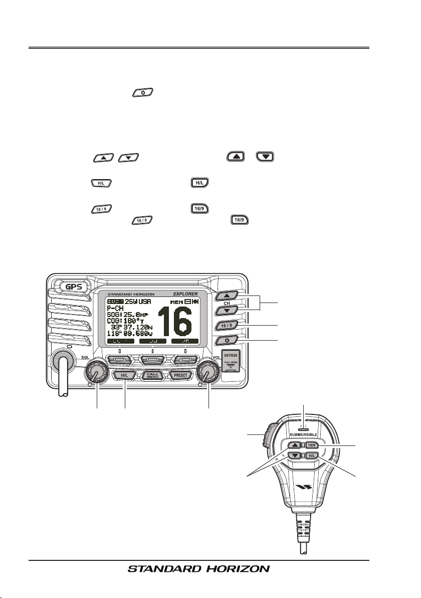
Quick RefeRence Guide
This transceiver is equipped with the E2O (Easy-To-Operate) system. You
can do the basic operation in numerical order in the illustration below.
Press and hold the button to turn on or off the radio.
Rotate the SQL knob counter clockwise to unsquelch the radio.
Rotate the VOL knob to adjust the speaker audio volume.
Rotate the SQL knob clockwise to the point where the noise not heard
from the speaker.
Press the / (or microphones / ) button to select the
operating channel.
Press the (or microphones ) button to toggle the transmit power
between High (25W) and Low (1W).
Press the (or microphones ) button to recall channel 16.
Press and hold the (or microphones ) button to recall channel 9.
Press again to revert to the last selected channel.
Place your mouth about 1/2 inch away from Mic hole and speak in a nor-
mal voice level while pressing the PTT switch.
Mic HOLe
GX1700Page 4

1 GENERAL INFORMATION
The STANDARD HORIZON EXPLOPER GPS GX1700 Marine VHF/FM Marine transceiver is capable of ITU-R 493-13 DSC (Digital Selective Calling)
Class D operation with a 12 channel internal GPS. Class D operation allows
continuous receiving of Digital Selective Calling functions on channel 70
even if the radio is receiving a call. The GX1700 VHF operates on all currently-allocated marine channels which are switchable for USA, International, or
Canadian regulations. Emergency channel 16 can be immediately selected
from any channel by pressing the red key. NOAA Weather channels
can also be accessed immediately by pressing the soft key.
The GX1700 can be operated from 11 to 16 VDC and has a switchable RF
output power of 1 watt or 25 watts.
Other features of the GX1700 VHF’s include: Slim design only 3.5” deep,
Noise canceling microphone with controls, optional RAM3 second station
remote-control microphone with display, intercom between radio and optional
RAM3, scanning, priority scanning, Dual Watch, DSC Position Polling up to 4
vessels, high and low voltage warning, and GPS repeatability.
2 PACKING LIST
When the package containing the transceiver is rst opened, please check it
for the following contents:
GX1700 Transceiver
Power Cord
Mounting Bracket and hardware
Owner’s Manual
DSC Warning Sticker
Flush Mount Template
3 OPTIONS
HC1600 ............................................................................ Dust Cover (White)
MMB-97 ..........................................................................Flush-Mount Bracket
CMP30B/W ...............Remote-Access Microphone (RAM3 Mic, Black/White)
CT-100 ................................................23-foot Extension Cable for RAM3 Mic
MLS-310 ............ 10W amplied External Speaker with on/off Volume control
MLS-300 ..................................................................... External Loud Speaker
Q7000619A .....................................External GPS antenna with 30Ft of cable
Page 5GX1700

4 ON-LINE WARRANTY REGISTRATION
(in USA or Canada only)
Please visit www.standardhorizon.com to register the GX1700 Marine VHF. It
should be noted that visiting the Web site from time to time may be benecial
to you, as new products are released they will appear on the STANDARD
HORIZON Web site.
PRODUCT SUPPORT INQUIRIES
If you have any questions or comments regarding the use of the GX1700,
you can visit the Marine Division of Vertex Standard Web site to send an EMail or contact the Product Support team at (800) 767-2450 M-F 8:00AM to
5:00PM PST.
GX1700Page 6

5 GETTING STARTED
5.1 PROHIBITED COMMUNICATIONS
The FCC prohibits the following communications:
• False distress or emergency messages:
• Messages to “any boat” except in emergencies and radio tests;
• Messages to or from a vessel on land;
• Transmission while on land;
• Obscene, indecent, or profane language (potential ne of $10,000).
5.2 ABOUT VHF RADIO
The radio frequencies used in the VHF marine band lie between 156 and
158 MHz with some shore stations available between 161 and 163 MHz.
The marine VHF band provides communications over distances that are essentially “line of sight” (VHF signals do not travel well through objects such
as buildings, hills or trees). Actual transmission range depends much more
on antenna type, gain and height than on the power output of the transmitter.
On a xed mount 25W radio transmission expected distances can be greater
than 15 miles, for a portable 5W radio transmission the expected distance
can be greater than 5 miles in “line of sight”.
5.3 SELECTING AN ANTENNA
Marine antennas are made to radiate signals equally in all horizontal directions, but not straight up. The objective of a marine antenna is to enhance
the signal toward the horizon. The degree to which this is accomplished is
called the antenna’s gain. It is measured in decibels (dB) and is one of the
major factors in choosing an antenna. In terms of effective radiated power
(ERP), antennas are rated on the basis of how much gain they have over
a theoretical antenna with zero gain. A 3 foot, 3dB gain antenna represents
twice as much gain over the imaginary antenna.
Typically a 3 foot 3dB gain stainless steel whip is used on a sailboat mast.
The longer 8 foot 6dB berglass whip is primarily used on power boats that
require the additional gain.
3dB
6dB
9dB
Page 7GX1700
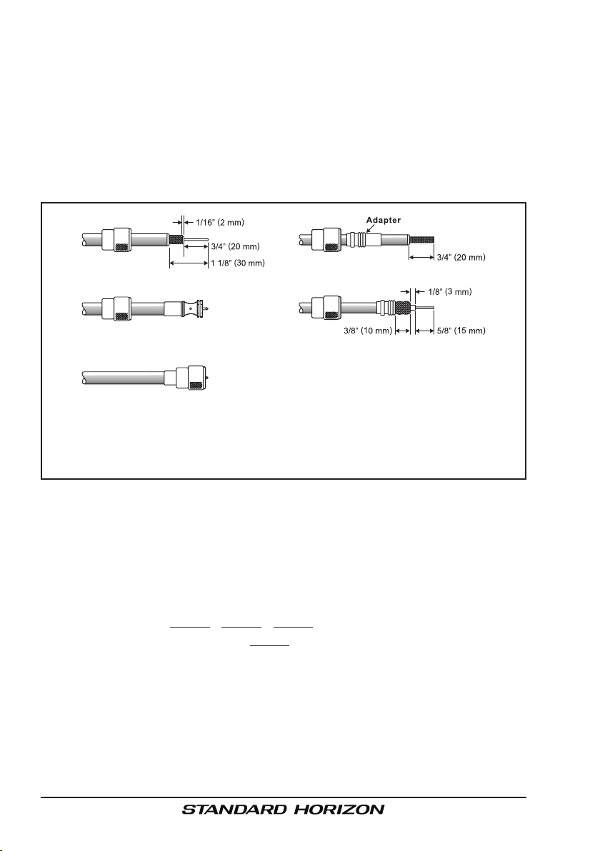
5.3.1 Coaxial Cable
VHF antennas are connected to the transceiver by means of a coaxial cable
– a shielded transmission line. Coaxial cable is specied by it’s diameter and
construction.
For runs less than 20 feet, RG-58/U, about 1/4 inch in diameter is a good
choice. For runs over 20 feet but less than 50 feet, the larger RG-8X or RG213/U should be used for cable runs over 50 feet RG-8X should be used. For
installation of the connector onto the coaxial cable refer to the gure below.
To get your coax cable through a tting and into your boat’s interior,
you may have to cut off the end plug and reattach it later. You can do
this if you follow the directions that come with the connector. Be sure
to make good soldered connections.
5.4 EMERGENCY (CHANNEL 16 USE
Channel 16 is known as the Hail and Distress Channel. An emergency may
be dened as a threat to life or property. In such instances, be sure the
transceiver is on and set to CHANNEL 16. Then use the following procedure:
1. Press the microphone push-to-talk switch and say “Mayday, Mayday,
Mayday. This is , , ” (your vessel’s name).
2. Then repeat once: “Mayday, ” (your vessel’s name).
3. Now report your position in latitude/longitude, or by giving a true or magnetic bearing (state which) to a well-known landmark such as a navigation aid or geographic feature such as an island or harbor entry.
4. Explain the nature of your distress (sinking, collision, aground, re, heart
attack, life-threatening injury, etc.).
5. State the kind of assistance your desire (pumps, medical aid, etc.).
6. Report the number of persons aboard and condition of any injured.
)
GX1700Page 8

7. Estimate the present seaworthiness and condition of your vessel.
8. Give your vessel’s description: length, design (power or sail), color and
other distinguishing marks. The total transmission should not exceed 1
minute.
9. End the message by saying “OVER”. Release the microphone button
and listen.
10. If there is no answer, repeat the above procedure. If there is still no response, try another channel.
NOTE
The GX1700 have DSC Distress calling, that can transmit a distress
call digitally to all ships with compatible DSC radios. Refer to section “9
DIGITAL SELECTIVE CALLING”.
5.5 CALLING ANOTHER VESSEL (CHANNEL 16 OR 9
Channel 16 may be used for initial contact (hailing) with another vessel.
However, its most important use is for emergency messages. This channel
must be monitored at all times except when actually using another channel.
It is monitored by the U.S. and Canadian Coast Guards and by other
vessels. Use of channel 16 for hailing must be limited to initial contact
only. Calling should not exceed 30 seconds, but may be repeated 3 times
at 2-minute intervals. In areas of heavy radio trafc, congestion on channel
16 resulting from its use as a hailing channel can be reduced signicantly
in U.S. 0waters by using channel 9 as the initial contact (hailing) channel
for non-emergency communications. Also hailing on channel 9, the calling
time should not exceed 30 seconds but may be repeated 3 times at 2-minute
intervals.
Prior to making contact with another vessel, refer to the channel charts in this
manual, and select an appropriate channel for communications after initial
contact. For example, Channels 68 and 69 of the U.S. VHF Charts are some
of the channels available to non-commercial (recreational) boaters. Monitor
your desired channel in advance to make sure you will not be interrupting
other trafc, and then go back to either channel 16 or 9 for your initial contact.
When the hailing channel (16 or 9) is clear, press the PTT button on the mic
and state the name of the other vessel you wish to call and then “this is” followed by the name of your vessel and your Station License (Call Sign) then
release the PTT button on the mic. When the other vessel returns your call,
immediately request another channel by pressing the PTT button on the mic
and saying “go to,” the number of the other channel, say “over” and release
)
Page 9GX1700

the PTT button on the mic. Then switch to the new channel. When the new
channel is not busy, call the other vessel.
After a transmission, say “over,” and release the microphone’s push-to-talk
(PTT) switch. When all communication with the other vessel is completed,
end the last transmission by stating your Call Sign and the word “out.” Note
that it is not necessary to state your Call Sign with each transmission, only at
the beginning and end of the contact.
Remember to return to Channel 16 when not using another channel. Some
radios automatically monitor Channel 16 even when set to other channels or
when scanning.
5.6 OPERATING ON CHANNELS 13 AND 67
Channel 13 is used at docks and bridges and by vessels maneuvering in
port. Messages on this channel must concern navigation only, such as meeting and passing in restricted waters.
Channel 67 is used for navigational trafc between vessels.
By regulation, power is normally limited to 1 Watt on these channels. Your radio is programmed to automatically reduce power to this limit on these channels. However, in certain situations it may be necessary to temporarily use a
higher power. See page 25 ( key) for means to temporarily override the
low-power limit on these two channels.
5.7 AUTOMATED RADIO CHECK SERVICE
In areas across the country, Sea Tow offers boaters a way to conduct radio
checks. To use Sea Tow’s free Automated Radio Check service, simply tune
your VHF radio to the appropriate channel for your location and conduct a radio check as you typically would. Upon releasing your radio’s microphone, the
system will play an automated message and relay your transmission back to
you, thereby letting you know how your signal will sound to other boaters.
GX1700Page 10

The Automated Radio Check Service is currently available in the areas listed
below.
West Coast South Carolina
Newport/LA - Ch. 27 Charleston - Ch. 27
San Diego - Ch. 27 Georgetown - Ch. 27
Northeast Myrtle Beach - Ch. 27
Central Connecticut - Ch. 24 Gulf of Mexico
Eastern Connecticut - Ch. 27 Galveston Bay - Ch. 27
Southern Connecticut - Ch. 24 Mobile - Ch. 26
Portland-Midcoast (Maine) - Ch. 27 New Orleans - Ch. 27
Boston - Ch. 27 Pensacola/Orange Beach (Ala.) - Ch. 27
Cape and Islands - Ch. 28 Georgia
South Shore (Mass.) - Ch. 26 Brunswick - Ch. 27
Rhode Island - Ch. 24 Tennessee
Central Hudson (NY) - Ch. 24 Fort Loudon - Ch. 28
Eastern Long Island - Ch. 28 Florida
Freeport (N.Y.) - Ch. 24 Carrabelle/St. Marks - Ch. 26 & 27
Great South Bay (N.Y.) - Ch. 27 Charlotte Harbor - Ch. 26
Lower New York - Ch. 28 Clearwater/Port Richey - Ch. 26 & 27
Huntington (N.Y.) - Ch. 28 Daytona - Ch. 26
Port Jefferson - Ch. 27 Destin - Ch. 26 & 27
Shinnecock / Moriches (N.Y.) - Ch. 24 & 27 Fort Lauderdale - Ch. 27
Services International (Southold) - Ch. 28 Fort Myers - Ch.27
Western LI Sound - Ch. 27 Horseshoe Beach - Ch. 26
Manasquan (N.J.) - Ch. 24 Islamorada - Ch. 26
Northern New Jersey - Ch. 27 Jacksonville - Ch. 27
Mid-Atlantic Key Biscayne - Ch. 26
Atlantic City (NJ) - Ch. 26 Key Largo - Ch. 27
Central New Jersey (NJ) - Ch. 27 Marco Island - Ch. 27
Sea Isle / Cape May (NJ) - Ch. 26 Naples - Ch. 26
Delaware River (DE) - Ch. 26 Palm Beach - Ch. 26
Northern Chesapeake (Md.) - Ch. 27 Panama City - Ch. 27
Central Chesapeake (Md.) - Ch. 27 Pensacola - Ch. 26 & 27
Lower Chesapeake(Va.) - Ch. 26 Port Canaveral - Ch. 26
Hampton Roads (Va.) - Ch. 28 Port St. Joe - Ch. 26
North Carolina Sarasota - Ch. 26
Albermarle Sound- Ch. 27 Sebastian - Ch. 27
Crystal Coast- Ch. 27 St. Augustine - Ch. 26
Ocean Isle Beach - Ch. 26 Services International
Oregon Inlet- Ch. 27 Tampa Bay - Ch. 27
Pamlico Sound - Ch. 27 Treasure Coast - Ch. 27
Wrightsville Beach - Ch. 26 & 27 Venice - Ch. 27
Puerto Rico Virgin Islands
Puerto Rico - Ch. 26 & 27 Virgin Islands - Ch. 27
(Summerland Keys)
- Ch. 27
Page 11GX1700

6 INSTALLATION
6.1 SAFETY / WARNING INFORMATION
This radio is restricted to occupational use, work related operations only
where the radio operator must have the knowledge to control the exposure
conditions of its passengers and bystanders by maintaining the minimum
separation distance of 0.89 m (2.92 feet). Failure to observe these restrictions will result in exceeding the FCC RF exposure limits.
Antenna Installation:
The antenna must be located at least 0.89 m (about 3 feet) away from passengers in order to comply with the FCC RF exposure requirements.
6.2 LOCATION
The radio can be mounted at any angle. Choose a mounting location that:
• is far enough from any compass to avoid any deviation in compass
reading due to the speaker magnet
• provides accessibility to the front panel controls
• allows connection to a power source and an antenna
• has nearby space for installation of a microphone hanger
• choose a mounting location that is at least 3 feet (1 m) away from the
radio’s antenna.
• choose a mounting location that the signal from the GPS satellite can
receive sufciently.
Note: To insure the radio does not affect the compass or radios performance
is not affected by the antenna location, temporarily connect the radio in the
desired location and:
a. Examine the compass to see if the radio causes any deviation
b. Connect the antenna and key the radio. Check to ensure the radio is
operating correctly by requesting a radio check.
6.3 MOUNTING THE RADIO
6.3.1 Supplied Mounting Bracket
The supplied mounting bracket allows overhead or desktop mounting.
See illustration on next page, use a 13/64” (5.2 mm) bit to drill the holes to a
surface which is more 0.4 inch (10 mm) thick and can support more than 3.3
lbs (1.5 kg) and secure the bracket with the supplied screws, spring washers,
at washers, and nuts.
GX1700Page 12
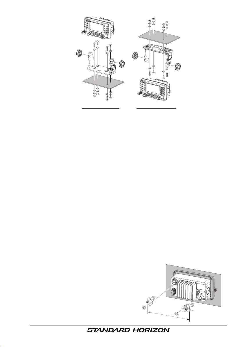
DeSktOp MOunting OVerHeaD MOunting
6.3.2 Optional MMB-97 Flush Mount Bracket
A GPS receiver and antenna is located in the front panel of the GX1700. In
many cases the radio may be ush mounted, however before cutting holes
to ush mount the radio it is recommended to temporarily connect the radio
to power and turn on in the location where it will be ush mounted to conrm
it is able to receive a GPS location on it’s display. If the radio is not able
to receive a location, a GPS Chart plotter with NMEA 0183 output or the
optional Standard Horizon external GPS antenna may be needed to receive
GPS satellite signals.
To use the optional Standard Horizon external GPS antenna (Q7000619A),
the GX1700 internal GPS Unit Power must be turned OFF (refer to section
“14.1 UNIT POWER”) and the GPS Selection changed to External GPS (refer
to section “14.9 GPS SELECTION”).
1. Use the supplied template to mark the location where the rectangular hole
is to be cut. Conrm the space behind the dash or panel is deep enough
to accommodate the transceiver (at least 3.54 inches (90 mm) deep).
There should be at least 1/2 inch (1.3 cm) between the transceiver’s
heatsink and any wiring, cables or structures.
2. Cut out the rectangular hole 2.82” H x 5.39” W (72 x 137 mm) and insert
the transceiver.
3. Fasten the brackets to the rear panel
of the transceiver (see illustration at
the right).
4. Turn the adjusting screw to adjust the
tension so that the transceiver is tight
against the mounting surface.
6.42” (163 mm
)
Adjusting Screw
Page 13GX1700
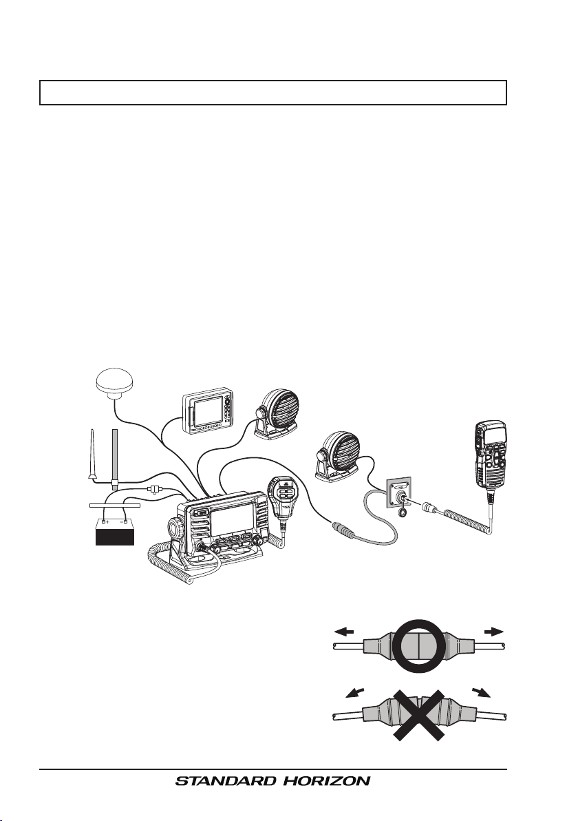
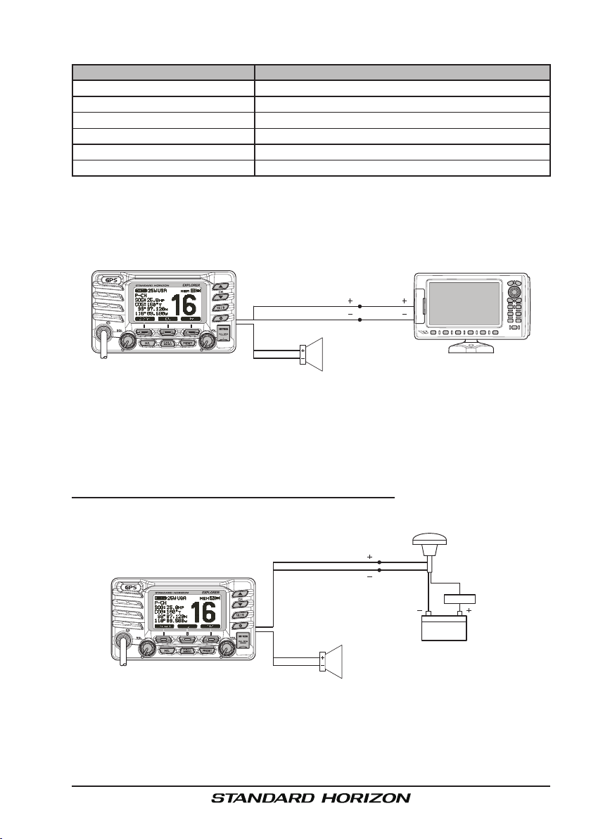
6.4 ELECTRICAL CONNECTIONS
CAUTION
Reverse polarity battery connections will damage the radio!
Connect the power cord and antenna to the radio. Antenna and Power Supply connections are as follows:
1. Mount the antenna at least 3 feet (1 m) away from the radio. At the rear
of the radio, connect the antenna cable. The antenna cable must have a
PL259 connector attached. RG-8/U coaxial cable must be used if the antenna is 25 feet (7.6 m) or more from the radio. RG58 cable can be used
for distances less than 25 feet (7.6 m).
2. Connect the red power wire to a 11.0 V to 16.5 V DC power source (Normal: 13.8 VDC). Connect the black power wire to a negative ground.
3. If an optional remote extension speaker is to be used, refer to section “6.5
ACCESSORY CABLE” for connections.
4. It is advisable to have a Certied Marine Technician check the power output and the standing wave ratio of the antenna after installation.
Optional GPS Antenna
Optional Chart Plotter
Optional Speaker
Antenna
Water proof
Deck Outlet
Fuse
Red
Black
Power Source
Fuse Replacement (125V 6A
)
Optional Speaker
To take out the Fuse from the Fuse Holder,
hold both ends of the Fuse Holder and pull the
Fuse Holder apart without bending the Fuse
Holder. When you replace the Fuse, please
confirm that the Fuse is tightly fixed on the
metal contact located inside the Fuse Holder.
If the metal contact holding the fuse is loose,
the Fuse holder may heat up.
Optional CMP30 Remote MIC
GX1700Page 14
6.5 ACCESSORY CABLE
Wire Color/Description Connection Examples
(–)
)
(–)
)
Connect to external 4 Ohm audio speaker
Connect to external 4 Ohm audio speaker
Connect to NMEA (+) output of GPS
Connect to NMEA
)
Connect to NMEA (+) intput of GPS
(–)
Connect to NMEA
(–)
output or common ground of GPS
(–)
input or common ground of GPS
WHITE - External Speaker (+
SHIELD - External Speaker
BLUE - NMEA GPS Input (+
GREEN - NMEA GPS Input
GRAY - NMEA DSC Output (+
BROWN - NMEA GPS Output
: Some GPS Chart plotters have a single wire for NMEA Signal Ground, if this is the case
connect the NMEA Input (–) and NMEA output (–) to the GPS Chart Plotters single NMEA
Signal Ground wire.
6.5.1 Internal GPS (DSC Output to a Chart Plotter
Plotter
Gray: NMEA DSC Output
Brown: NMEA DSC Output
Radio Wires
White
Shield
Connection
( )
GPS Input
( )
GPS Input
External Speaker
6.5.2 External GPS or Chart Plotter (for GPS
)
Chart Plotter
( )
( )
)
The connections below are used when the internal GPS cannot receive a
Fix. The GX1700 Internal GPS must be turned off (refer to section “14.9
UNIT POWER”) and the GPS Selection must be selected to External GPS
(refer to section “14.9 GPS SELECTION”).
6.5.2.1 GPS Input - Standard Horizon GPS Antenna
Standard Horizon
GPS Antenna
Par Q7000619A
Radio Wires
Blue: NMEA GPS Input
Green: NMEA GPS Input
White
Shield
Note: The GPS antenna is supplied with 30ft of cable
and a connector. To connect the GPS antenna to the
radio, cut off the 5 pin antenna connector, strip the white
insulation to expose the Red, Black and Brown wires and
connect as shown in the diagram. All other wires are not
used and may be cut off. The 2 amp fuse is not included.
( )
Brown
( )
Black
Black
External Speaker
( ) ( )
t #:
Red
2 A Fuse
12 V Battery
Page 15GX1700
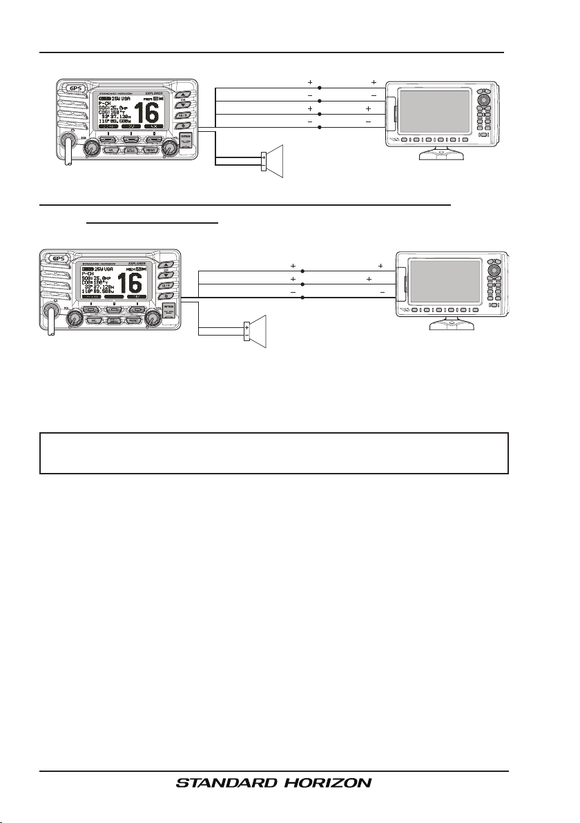
6.5.2.2 GPS Input and DSC Output GPS Chart Plotter (RS422 Connections)
Plotter
( )
( )
( )
( )
Connection
NMEA Output
NMEA Output
NMEA Input
NMEA Input
( )
( )
( )
( )
Chart Plotter
Blue: NMEA GPS Input
Green: NMEA DSC Input
Gray: NMEA DSC Output
Brown: NMEA DSC Output
Radio Wires
White
Shield
External Speaker
6.5.2.3 Standard Horizopn GPS Chart Plotter or Other Chart Plotter
(RS232 Connections)
Standard Horizon
Radio Wires
Blue: NMEA GPS Input
Gray: NMEA DSC Output
Green & Brown: Ground
White
Shield
External Speaker
Plotter
Connection
( )
Brown: NMEA Output
( )
Blue: NMEA Input
( )
Green: NMEA Ground
( )
( )
( )
Chart Plotter
When connecting the External Speaker, Chart Plotter, or External GPS Antenna, strip off about 1 inch (2.5 cm) of the specied wire’s insulation, then
splice the ends together.
CAUTION
Care must be taken not to touch any of the NMEA wires (blue, gray
or brown) to positive 12 VDC or the radio may be damaged.
External GPS Connections (4800 baud)
When the GPS reception is limited, such as the flush mounting of the
GX1700, the NMEA input (+) (Blue) and NMEA input (-) (Green) wires may
be connected to the NMEA output connections of a external GPS antenna
or GPS Chart Plotter. To change the GX1700 from using the internal GPS
antenna to the external GPS antenna, refer to section “14.9 GPS SELEC-
TION” (for selection), and “14.1 UNIT POWER” (for turn off).
NMEA INPUT (GPS Information)
• The GPS must have the NMEA Output turned on and set to 4800 Baud
in the setup menu. If there is a selection for parity select none.
• For further information on interfacing /setting up your GPS. Please contact the manufacturer of the GPS receiver.
• GX1700 can read NMEA-0183 version 2.0 or higher.
GX1700Page 16
• The NMEA 0183 input sentences are GLL, GGA, RMC and GNS (RMC
sentence is recommended).
NMEA Output (DSC)
The NMEA 0183 output sentences are DSC and DSE.
If you have further inquires, please feel free to contact Product Support at:
Phone: (800) 767-2450
Email: marinetech@vxstdusa.com
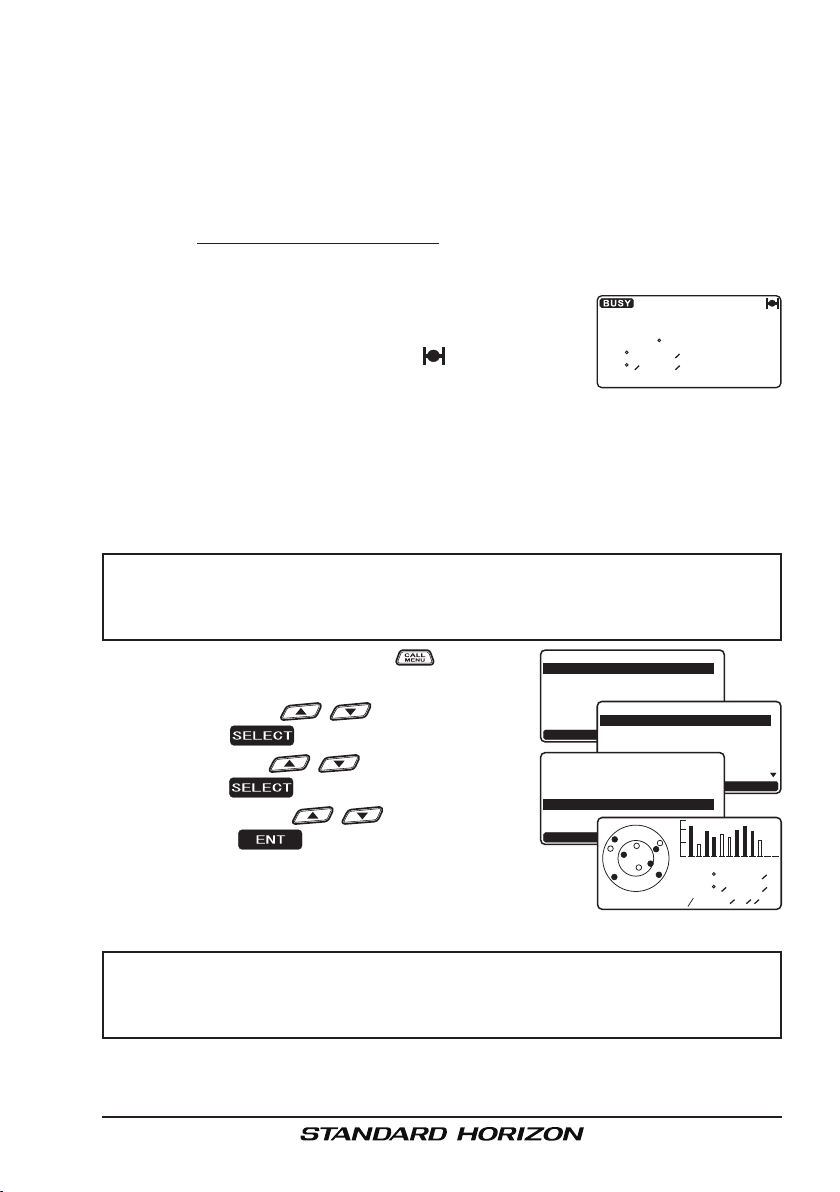
6.6 CHECKING GPS STATUS
When the GX1700 receives the GPS signal from the
internal GPS, or from an External GPS antenna or
Chart plotter, a small satellite icon ( ) will appear on
the top right corner of the display and your current location (Latitude/Longitude) is shown on the display.
The GX1700 has a GPS status display which shows the satellites currently
being received, along with a graphical (bar-graph) representation of the relative signal strengths from the satellites.
NOTE
For the GX1700 to properly show the GPS status page when a
external GPS antenna or a Chart Plotter is connected it must be
setup to output GSA and GSV NMEA 0183 sentences.
1. Press an d hold down the key un t i l
Setup Menu
“
SETUP
” appears, then select “
” with the / key.
GENERAL
2. Press the soft key, then select “
PLAY
” with the / key.
3. Press the soft key, then select “
STATUS
” with the / key.
GPS
4. Press the soft key to display the
GENERAL SETUP
CH Function Setup
DSC Setup
Waypoint Setup
GPS Setup
MMSI Setup
SELECT
DIS-
Normal
Compass
Waypoint
GPS STATUS
ENT
GPS status currently being received.
5. Press any key to return to normal operation.
25W USA
SOG:25.0
COG:123
118 09.580
LOC AM
-Setup Menu-
-Display-
3D 1FT 10:00
MP
T
33 37.120
DISPLAY
Dimmer
Contrast
Unit of Measure
Key Beep
Station Name
SELECT
N
16
W
12:56
-General Menu-
DISTRESS
QUIT
QUIT
1
2 2 0
1 1 3 6
0 8 879
33 37.120
118 09.580
/
12 25
QUIT
0 0 21 1 1
4
N
W
NOTE
When the GX1700 is first turned on, it may take several minutes
to compute a x of your position. This is normal, as the GX1700 is
downloading “almanac” information from the GPS satellites.
Page 17GX1700
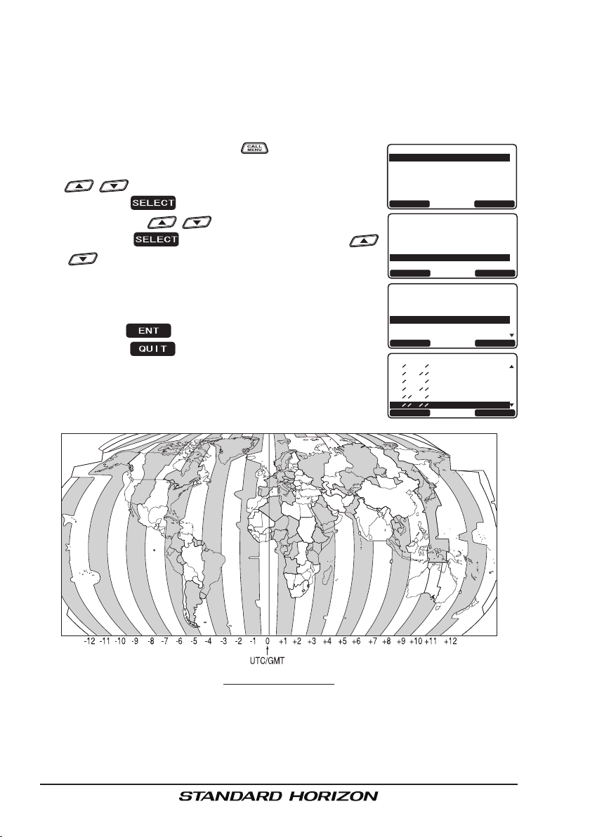
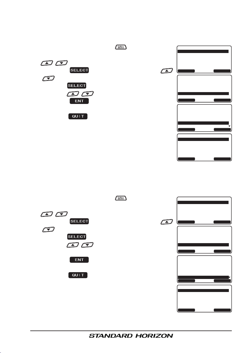
6.7 CHANGING THE GPS TIME
From the Factory the GX1700 shows GPS satellite time or UTC (Universal
Time Coordinated or GPS Satellite Time). A time offset is needed to show the
local time in your area. Please see the Offset Time Table at the bottom of this
page.
1. Press and hold down the key until “
Menu
” appears, then select “
GPS SETUP
Setup
” with the
/ key.
2. Press the soft key, then select “
SET
” with the / key.
TIME OFF-
3. Press the soft key, then press the
/ key to select time offset of your location. See
illustration below to nd your offset time. If “
00:00
is assigned, the time is the same as UTC (Universal
Time Coordinated or GPS Satellite Time).
4. Press the soft key to store the time offset.
5. Press the soft key several times to return
to radio operation.
-Setup Menu-
GENERAL SETUP
CH Function Setup
DSC Setup
Waypoint Setup
GPS Setup
MMSI Setup
SELECT
-Setup MenuGeneral Setup
CH Function Setup
DSC Setup
Waypoint Setup
GPS SETUP
MMSI Setup
SELECT
”
-GPS Setup-
Unit Power
Coodinate System
Pinning
TIME OFFSET
Time Area
Time Display
SELECT
-Time Offset+02:30
+02:00
+01:30
+01:00
+00:30
00:00
ENT
QUIT
QUIT
QUIT
QUIT
tiMe OffSet tabLe
GX1700Page 18
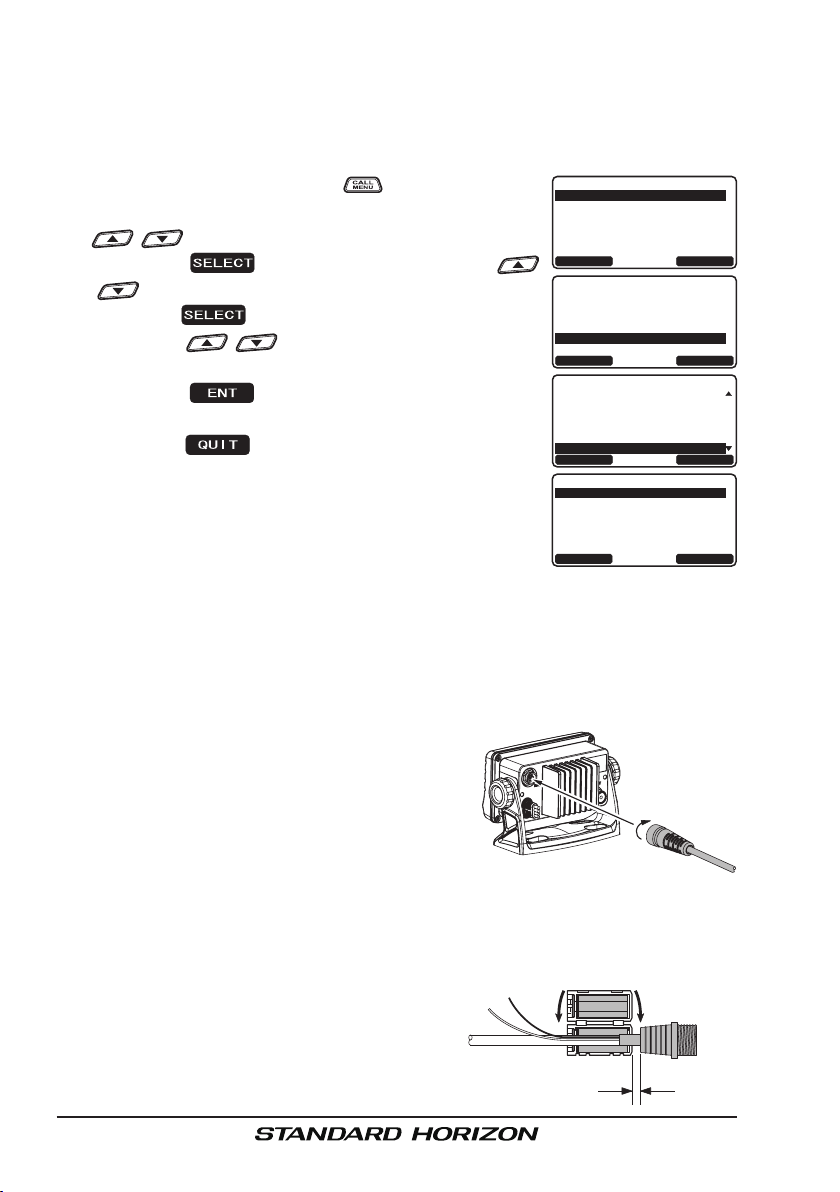
6.8 CHANGING THE TIME AREA
This menu selection allows the radio to show UTC (Universal Time Coordinated or GPS Satellite Time) or local time with the offset.
1. Press and hold down the key until “
Menu
” appears, then select “
GPS SETUP
Setup
” with the
/ key.
2. Press the soft key, then press the
/ key to “
TIME AREA
”.
3. Press the soft key.
4. Press the / key to select “
UTC
” or “
LOCAL
”.
5. Press the soft key to store the selected
setting.
6. Press the soft key several times to return
to radio operation.
-Setup Menu-
GENERAL SETUP
CH Function Setup
DSC Setup
Waypoint Setup
GPS Setup
MMSI Setup
SELECT
-Setup MenuGeneral Setup
CH Function Setup
DSC Setup
Waypoint Setup
GPS SETUP
MMSI Setup
SELECT
-GPS Setup-
Unit Power
Coodinate System
Pinning
Time Offset
TIME AREA
Time Display
SELECT
-Time Area-
UTC
Local
ENT
QUIT
QUIT
QUIT
QUIT
6.9 CHANGING THE TIME DISPLAY
This menu selection allows the radio to setup to show time in 12-hour or 24hour format.
1. Press and hold down the key until “
Menu
” appears, then select “
GPS SETUP
Setup
” with the
/ key.
2. Press the soft key, then press the
/ key to select “
TIME DISPLAY
”.
3. Press the soft key.
4. Press the / key to select “
HOUR
”.
12 HOUR
” or “
24
5. Press the soft key to store the selected
setting.
6. Press the soft key several times to return
to radio operation.
-Setup Menu-
GENERAL SETUP
CH Function Setup
DSC Setup
Waypoint Setup
GPS Setup
MMSI Setup
SELECT
-Setup MenuGeneral Setup
CH Function Setup
DSC Setup
Waypoint Setup
GPS SETUP
MMSI Setup
SELECT
-GPS Setup-
Unit Power
Coodinate System
Pinning
Time Offset
Time Area
TIME DISPLAY
SELECT
-Time Display-
12HOUR
24hour
QUIT
QUIT
QUIT
ENT
QUIT
Page 19GX1700
6.10 CHANGING COG TO TRUE OR MAGNETIC
Allows the GPS Course Over Ground to be selected to show in True or Magnetic. Factory default is True however by following the steps below the COG
can be changed to Magnetic.
1. Press and hold down the key until “
Menu
” appears, then select “
GPS SETUP
Setup
” with the
/ key.
2. Press the soft key, then press the
/ key to select “
MAGNETIC
”.
3. Press the soft key.
4. Press the / key to select “
TRUE
“
”.
MAGNETIC
” or
5. Press the soft key to store the selected
setting.
6. Press the soft key several times to return
to radio operation.
-Setup Menu-
GENERAL SETUP
CH Function Setup
DSC Setup
Waypoint Setup
GPS Setup
MMSI Setup
SELECT
-Setup MenuGeneral Setup
CH Function Setup
DSC Setup
Waypoint Setup
GPS SETUP
MMSI Setup
SELECT
-GPS Setup-
Coodinate System
Pinning
Time Offset
Time Area
Time Display
MAGNETIC
SELECT
-Magnetic-
TRUE
Magnetic
QUIT
QUIT
QUIT
ENT
QUIT
6.11 OPTIONAL RAM3 (CMP30) INSTALLATION
The GX1700 is capable of using a RAM3 (CMP30) Remote Station Microphone to remotely control the Radio and DSC functions. In addition the
GX1700 can operate as a full function intercom system between the RAM3
and the radio.
1. Connect the Extension Cable to the Remote Mic eight pin connector on the rear
panel, then tighten the Cable Nut (see illustration at the right).
2. Install the ferrite core (supplied with the
RAM3 (CMP30) Remote Station Micro-
phone) to the Extension Cable, then snap its two halves together, per the
illustration below.
3. Attach the ferrite core as close as possible to the MIC plug, as shown.
4. Finally, wind some plastic tape
around each ferrite core, to prevent vibration from causing the
two halves to split apart.
External Speaker
Connections
Routing Cable or
CT-100 Extension Cable
As close as possible
Ferrite Core
Snap together
GX1700Page 20
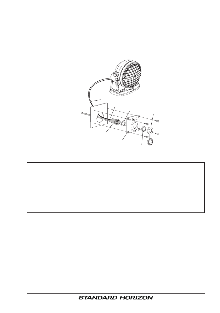
5. Referring to illustration below, make a 1.2” (30 mm) hole in the wall, then
insert the Extension Cable into this hole. Connect the Gasket and Mount
Base to the Extension Cable Connector using the Nut.
6. Drill the four Screw holes (approx. 2 mm) on the wall, then install the
Mounting Base to the wall using four screws.
7. Put the Rubber Cap on to the Nut. The installation is now complete.
External Speaker Connections
Ferrite Core
Wall
Routing Cable
Mounting Bracket
Gasket
Cap
Nut
NOTE
The routing cable can be cut and spliced, however care needs to be
taken when reconnecting the wires to ensure water integrity.
Before cutting the cable make sure it is not plugged into the radio.
After cutting you will notice there are the following wires:
Brown, Purple, Blue, Green, White, Shield
The White and shield wires are wrapped in foil. Remove the foil,
and separate the White and shield wires.
Page 21GX1700
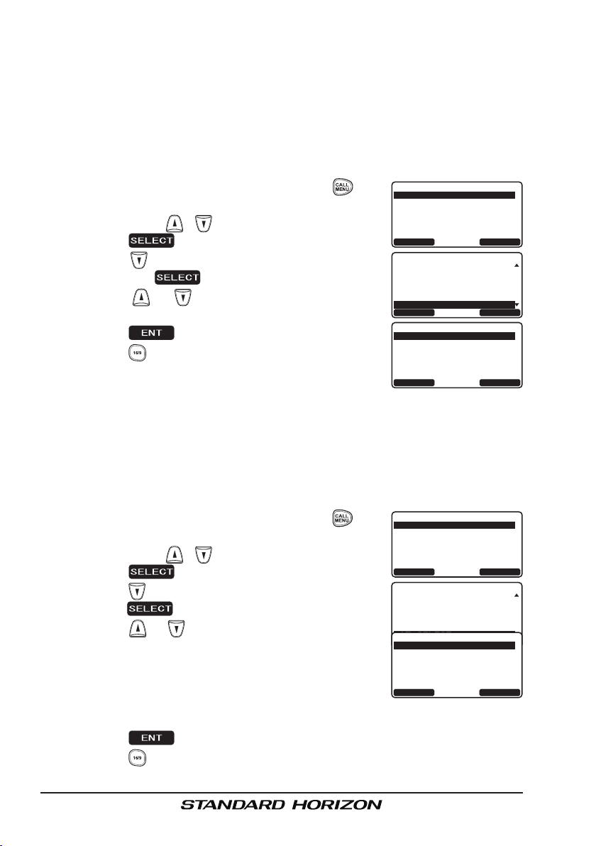
6.11.1 Connecting an External Speaker to the RAM3 Mic Cable
In noisy locations and optional external speaker may be connected to the
white speaker wires on the RAM3 routing cable (refer to previous page). The
RAM3 can drive the internal speaker or the external speaker one at a time.
When connecting an external speaker, follow the procedure below to turn off
the RAM3 audio and enable the external speaker wires on the RAM3 routing
cable.
1. On the RAM3 mic, press and hold the key
Setup Menu
until “
SETUP
” with the / key.
” appears, then select “
GENERAL
2. Press the soft key.
3. Press the key to until “
EXT SPEAKER
” is shown
and press the soft key.
4. Press the or key to select “
OFF
” (External
speaker off) or “ON” (External speaker on).
5. Press the soft key to save the selection.
-Setup Menu-
GENERAL SETUP
CH Function Setup
DSC Setup
Waypoint Setup
GPS Setup
MMSI Setup
SELECT
-General MenuContrast
Unit of Measure
Key Beep
Station Name
Soft Keys
EXT SPEAKER
SELECT
-EXT Speaker-
ON
Off
QUIT
QUIT
6. Press the key to exit this mode.
ENT
QUIT
6.11.2 External Speaker AF Selection
AF Select
The “
external speaker wires (on routing cable) to a xed level regardless of the
volume level setting of the RAM3. This is useful when using the optional
MLS-310 amplied speaker with on/off volume control.
1. On the RAM3 mic, press and hold the key
until “
SETUP
2. Press the soft key.
3. Press the key to until “
press the soft key.
4. Press the or key to select “
nal Speaker Level is “Fixed”) or “
Speaker Level is “Adjustable”).
“Fixed” use when MLS-310 is connected.
“Adjustable” use when MLS-300 or other speaker
without volume control is connected.
5. Press the key to save the selection.
6. Press the key to exit this mode.
” menu allows you to set the audio output level of the RAM3
-Setup Menu-
GENERAL SETUP
Setup Menu
” appears, then select “
” with the / key.
AF SELECT
PRE-OUT
PA-OUT
GENERAL
” is shown and
” (Exter-
” (External
CH Function Setup
DSC Setup
Waypoint Setup
GPS Setup
MMSI Setup
SELECT
-General MenuUnit of Measure
Key Beep
Station Name
Soft Keys
EXT Speaker
AF SELECT
-EXT Speaker-
SELECT
PRE-OUT
Pa-out
ENT
QUIT
QUIT
QUIT
GX1700Page 22

MEMO
_ _ _ _ _ _ _ _ _ _ _ _ _ _ _ _ _ _ _ _ _ _ _ _ _ _ _ _ _ _ _ _ _ _
_ _ _ _ _ _ _ _ _ _ _ _ _ _ _ _ _ _ _ _ _ _ _ _ _ _ _ _ _ _ _ _ _ _
_ _ _ _ _ _ _ _ _ _ _ _ _ _ _ _ _ _ _ _ _ _ _ _ _ _ _ _ _ _ _ _ _ _
_ _ _ _ _ _ _ _ _ _ _ _ _ _ _ _ _ _ _ _ _ _ _ _ _ _ _ _ _ _ _ _ _ _
_ _ _ _ _ _ _ _ _ _ _ _ _ _ _ _ _ _ _ _ _ _ _ _ _ _ _ _ _ _ _ _ _ _
_ _ _ _ _ _ _ _ _ _ _ _ _ _ _ _ _ _ _ _ _ _ _ _ _ _ _ _ _ _ _ _ _ _
_ _ _ _ _ _ _ _ _ _ _ _ _ _ _ _ _ _ _ _ _ _ _ _ _ _ _ _ _ _ _ _ _ _
_ _ _ _ _ _ _ _ _ _ _ _ _ _ _ _ _ _ _ _ _ _ _ _ _ _ _ _ _ _ _ _ _ _
_ _ _ _ _ _ _ _ _ _ _ _ _ _ _ _ _ _ _ _ _ _ _ _ _ _ _ _ _ _ _ _ _ _
_ _ _ _ _ _ _ _ _ _ _ _ _ _ _ _ _ _ _ _ _ _ _ _ _ _ _ _ _ _ _ _ _ _
_ _ _ _ _ _ _ _ _ _ _ _ _ _ _ _ _ _ _ _ _ _ _ _ _ _ _ _ _ _ _ _ _ _
_ _ _ _ _ _ _ _ _ _ _ _ _ _ _ _ _ _ _ _ _ _ _ _ _ _ _ _ _ _ _ _ _ _
_ _ _ _ _ _ _ _ _ _ _ _ _ _ _ _ _ _ _ _ _ _ _ _ _ _ _ _ _ _ _ _ _ _
_ _ _ _ _ _ _ _ _ _ _ _ _ _ _ _ _ _ _ _ _ _ _ _ _ _ _ _ _ _ _ _ _ _
_ _ _ _ _ _ _ _ _ _ _ _ _ _ _ _ _ _ _ _ _ _ _ _ _ _ _ _ _ _ _ _ _ _
_ _ _ _ _ _ _ _ _ _ _ _ _ _ _ _ _ _ _ _ _ _ _ _ _ _ _ _ _ _ _ _ _ _
_ _ _ _ _ _ _ _ _ _ _ _ _ _ _ _ _ _ _ _ _ _ _ _ _ _ _ _ _ _ _ _ _ _
_ _ _ _ _ _ _ _ _ _ _ _ _ _ _ _ _ _ _ _ _ _ _ _ _ _ _ _ _ _ _ _ _ _
_ _ _ _ _ _ _ _ _ _ _ _ _ _ _ _ _ _ _ _ _ _ _ _ _ _ _ _ _ _ _ _ _ _
_ _ _ _ _ _ _ _ _ _ _ _ _ _ _ _ _ _ _ _ _ _ _ _ _ _ _ _ _ _ _ _ _ _
_ _ _ _ _ _ _ _ _ _ _ _ _ _ _ _ _ _ _ _ _ _ _ _ _ _ _ _ _ _ _ _ _ _
_ _ _ _ _ _ _ _ _ _ _ _ _ _ _ _ _ _ _ _ _ _ _ _ _ _ _ _ _ _ _ _ _ _
_ _ _ _ _ _ _ _ _ _ _ _ _ _ _ _ _ _ _ _ _ _ _ _ _ _ _ _ _ _ _ _ _ _
_ _ _ _ _ _ _ _ _ _ _ _ _ _ _ _ _ _ _ _ _ _ _ _ _ _ _ _ _ _ _ _ _ _
_ _ _ _ _ _ _ _ _ _ _ _ _ _ _ _ _ _ _ _ _ _ _ _ _ _ _ _ _ _ _ _ _ _
_ _ _ _ _ _ _ _ _ _ _ _ _ _ _ _ _ _ _ _ _ _ _ _ _ _ _ _ _ _ _ _ _ _
_ _ _ _ _ _ _ _ _ _ _ _ _ _ _ _ _ _ _ _ _ _ _ _ _ _ _ _ _ _ _ _ _ _
_ _ _ _ _ _ _ _ _ _ _ _ _ _ _ _ _ _ _ _ _ _ _ _ _ _ _ _ _ _ _ _ _ _
_ _ _ _ _ _ _ _ _ _ _ _ _ _ _ _ _ _ _ _ _ _ _ _ _ _ _ _ _ _ _ _ _ _
_ _ _ _ _ _ _ _ _ _ _ _ _ _ _ _ _ _ _ _ _ _ _ _ _ _ _ _ _ _ _ _ _ _
_ _ _ _ _ _ _ _ _ _ _ _ _ _ _ _ _ _ _ _ _ _ _ _ _ _ _ _ _ _ _ _ _ _
_ _ _ _ _ _ _ _ _ _ _ _ _ _ _ _ _ _ _ _ _ _ _ _ _ _ _ _ _ _ _ _ _ _
_ _ _ _ _ _ _ _ _ _ _ _ _ _ _ _ _ _ _ _ _ _ _ _ _ _ _ _ _ _ _ _ _ _
Page 23GX1700
7 CONTROLS AND INDICATORS
NOTE
This section denes each control of the transceiver. For operating instructions refer to section “8 BASIC OPERATION”.
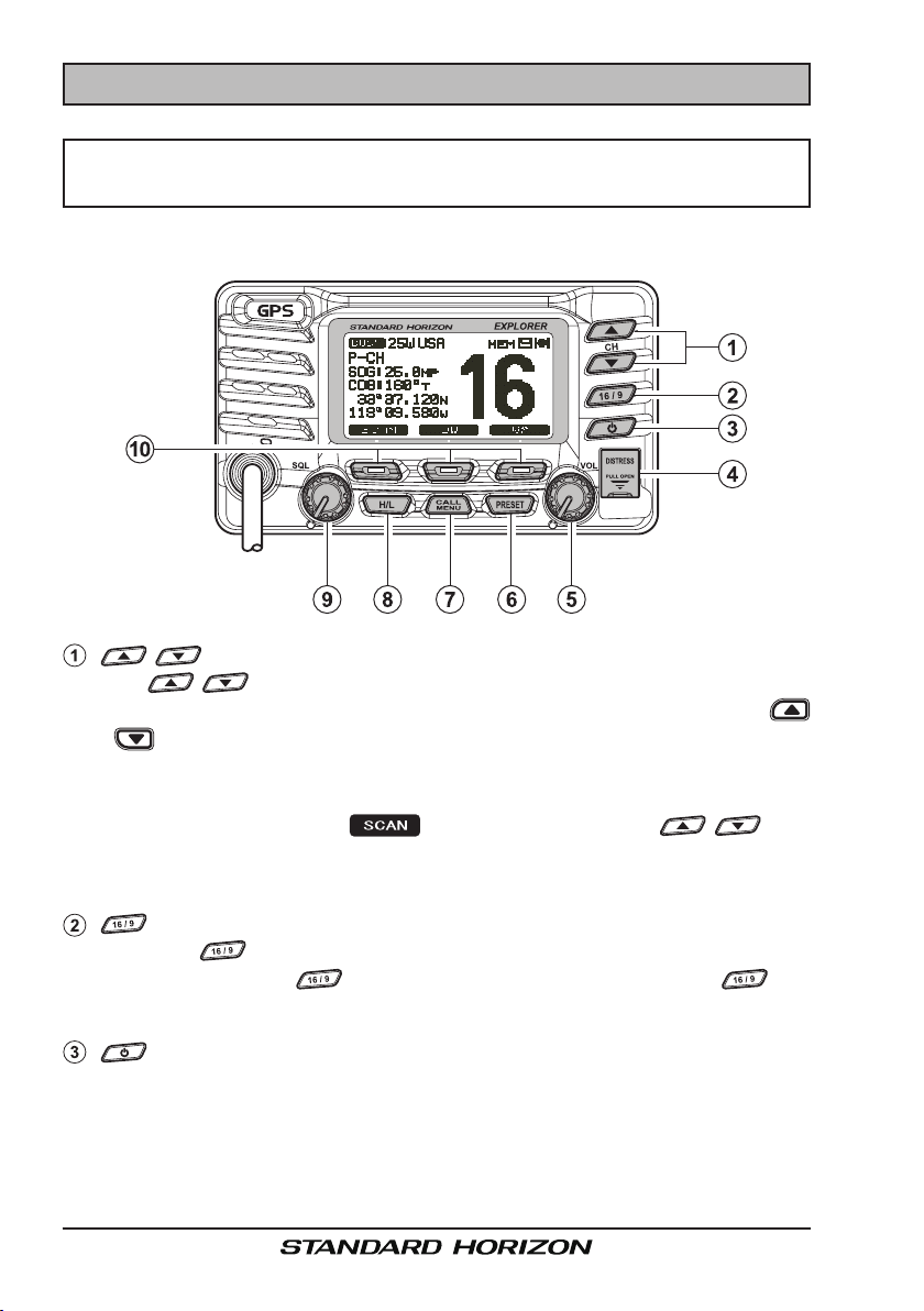
7.1 FRONT PANEL
/ Key
The / keys are used to select channels and to choose menu
items (such as the DSC menu, Radio Setup and DSC Setup menu).
/ keys on the microphone can also be used to select channels and
menu items.
SecOnDary uSe
While holding down the soft key and pressing / key,
you can conrm memory channels that have been programmed for scan-
ning.
Key
Press the key briey to recall channel 16 from any channel.
Press and hold the key to recall channel 9. Pressing the key
again reverts to the previous selected working channel.
Key
Turns the transceiver on and off. To turn the transceiver on, press and
hold this key until the LCD turns on. To turn it off, press and hold this key
until the LCD turns off. When the power is turned on, the transceiver is
set to the last-selected channel.
GX1700Page 24
Key
Used to send a DSC Distress Alert. To transmit a Distress Alert refer to
section “9.2.2 Programming the MMSI” and “9.3.1 Transmitting a DSC
Distress Alert”.
VOL Knob (Volume Control Knob
Adjusts the audio volume level. Turn this knob clockwise to increase the
audio volume level.
SecOnDary uSe
When a RAM3 is connected and intercom mode is selected, controls the
listen volume of the audio from the RAM3.
Key
Press this key to select the Preset Memory Bank, “P SET” will be shown
on the display. To exit Preset Memory bank, press the
or press the
preset channel. Refer to section “8.10.1 Preset Channel Programming”
to program the Preset channels.
Key
Press the key to access the “DSC MENU”.
SecOnDary uSe
Press and hold the key to access the “SETUP MENU”.
Key
Press the
Channel 16 and 67 (navigation/Bridge channels) are set 1 W, however
when the
porarily changed to 25 W until the PTT on the microphone is pressed
and released. The
low power only channels.
key. Press the
key to toggle between 25 W (High) and 1 W (Low) power.
key is pressed the power on these channels may be tem-
key does not function on transmit inhibited and
)
key again
or key to select the desired
SQL Knob (Squelch Control
Adjusting this control clockwise, sets the point at which random noise
on the channel does not activate the audio circuits but a received signal
does. This point is called the squelch threshold. Further adjustment of
the squelch control will degrade reception of wanted transmissions.
Soft Keys
The 3 soft keys functions can be customized by the Setup Menu mode
section “10.7 SOFT KEYS”. When one of the soft keys is pressed briey,
the functions will appear above each key on the display.
The factory defaults are Key 1: , Key 2: , and Key 3:
function.
)
Page 25GX1700

7.2 REAR PANEL
RAM3 Connector (Remote Station Microphone Connector
Connects the GX1700 to the RAM3 (CMP30) Remote Station Micro-
phone. Refer to section “15 RAM3 (CMP30) REMOTE MIC OPERA-
TION” for details
DC Input Cable
Connects the radio to a DC power supply capable of delivering 11 to 16V
DC.
Accessory Connection Cable (Green, Blue, Gray, & Brown
Connects the GX1700 to a Chart Plotter or external GPS Antenna. Refer
to section “6.5 ACCESSORY CABLE”.
External Speaker Connection Cable (White & Shield
Connects the GX1700 to an external speaker. See section “3 OPTIONS”
for a list of optional STANDARD HORIZON Speakers.
GND Terminal (Ground Terminal
Connecting a Ground wire to this connection will help reduce engine
noise when receiving and transmitting.
Use the screw supplied with the radio only.
ANT Jack (Antenna Jack
Connects an antenna to the transceiver. Use a marine VHF antenna with
an impedance of 50 ohms.
)
)
)
)
)
GX1700Page 26
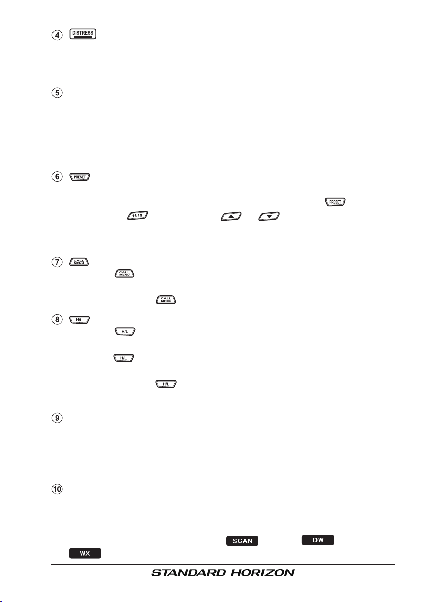
7.3 MICROPHONE
PTT (Push-To-Talk) Switch
When in radio mode and the PTT
switch pressed, the transmitter is
enabled for voice communications
to another vessel.
When a optional RAM3 second
station microphone is connected
and intercom mode is selected,
pressing the PTT switch enables
voice communications from the
GX1700 to the RAM3 second station microphone.
/ Keys
The and keys on the
microphone function the same as the and keys on the front
panel of the transceiver.
Microphone
When spoken into transmits your voice with reduction of background
noise, using Clear Voice Noise Reduction Technology.
NOTE
Be sure your mouth is about 1/2 inch (1.3 cm) from the mic hole
for best performance.
Key
The key on the microphone functions the same as the key on
the front panel of the transceiver.
Immediately recalls channel 16 from any channel location. Holding down
this key recalls channel 9. Pressing the key again reverts to the previously selected working channel.
Key
The key on the microphone functions the same as the key on
the front panel of the transceiver.
Press this key to toggle the transmit output power between 25 W (High)
and 1 W (Low) power.
Page 27GX1700
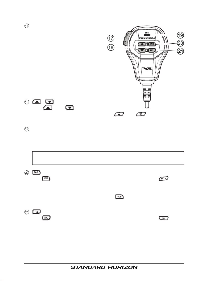
8 BASIC OPERATION
8.1 RECEPTION
1. After the transceiver has been installed, ensure that the power supply
and antenna are properly connected.
2. Press and hold the key until the radio turns on.
3. Rotate the SQL knob fully counterclockwise until “ ” is shown on
the display. This state is known as “unsquelched”.
4. Rotate the VOL knob until noise or audio from the speaker is at a comfortable level.
5. Rotate the SQL knob clockwise until the random noise disappears and
the “ ” icon is turned off. This state is known as the “squelch
threshold.”
6. Press the / key to select the desired channel. Refer to section
“17 CHANNEL ASSIGNMENTS” for available channels.
7. When a message is received, adjust the volume to the desired listening
level. The “ ” indicator on the display indicates communications is
being received or the radio is unsquelched.
8.2 TRANSMISSION
1. Perform steps 1 through 6 of RECEPTION.
2. Before transmitting, monitor the channel to ensure it is clear.
THIS IS AN FCC REQUIREMENT!
3. Press the PTT (push-to-talk) switch. The “
is displayed.
4. Speak slowly and clearly into the microphone.
5. When the transmission is nished, release the PTT switch.
NOTE
This is a noise-canceling microphone. Position the Oval Slot label
“MIC” within 1/2 inch (1.3 cm) from the mouth for optimum performance.
TX
” indicator on the LCD
8.3 TRANSMIT TIME - OUT TIMER (TOT
When the PTT switch on the microphone is held down, transmit time is limited to 5 minutes. This limits unintentional transmissions due to a stuck PTT
switch inside the microphone. About 10 seconds before automatic transmitter
shutdown, a warning beep will be heard from the speaker(s). The transceiver
will automatically go to receive mode, even if the PTT switch is continually
held down. Before transmitting again, the PTT switch must rst be released
and then pressed again.
)
GX1700Page 28

8.4 SIMPLEX/DUPLEX CHANNEL USE
Refer to section “17 CHANNEL ASSIGNMENTS” for instructions on use of
simplex and duplex channels.
NOTE
All channels are factory-programmed in accordance with FCC (USA),
Industry Canada, and International regulations. Mode of operation
cannot be altered from simplex to duplex or vice-versa.
8.5 DISPLAY TYPE
The GX1700 display can be setup to show displays other than the default
“NORMAL” display by using the procedure below:
25W USA
P-CH
SOG:25.0
COG:123
118 09.580
LOC AM
33 37.120
12:56
MP
T
N
W
DISTRESS
N
W
S
North Up
25W
SOG:25.0
E
COG:123
33 37.120
118 09.580
LOC AM
“nOrMaL” DiSpLay “cOMpaSS” DiSpLay
N
W
Range 50NM
E
S
“WaypOint” DiSpLay
1. Press and hold down the key until “
Menu
” appears, then select “
16
25W
BRG:300
DST:45.0
118 09.580
LOC AM
33 37.120
12:56
T
NM
GENERAL SETUP
N
W
3D 1FT 10:00
“gpS StatuS” DiSpLay
1
2 2 0
1 1 3 6
0 8 879
33 37.120
118 09.580
/
12 25
Setup
” with
the / key.
2. Press the soft key, then press the
/ key to select “
DISPLAY
”.
3. Press the soft key.
4. Press the / key to select desired screen
NORMAL
“
TUS
”.
COMPASS
”, “
WAYPOINT
”, “
” or “
GPS STA-
5. Press the soft key to store the selected
setting.
6. Press the soft key several times to return
to radio operation.
16
MP
T
N
W
12:56
0 0 21 1 1
4
N
W
-Setup Menu-
GENERAL SETUP
CH Function Setup
DSC Setup
Waypoint Setup
GPS Setup
MMSI Setup
SELECT
-General Menu-
DISPLAY
Dimmer
Contrast
Unit of Measure
Key Beep
Station Name
SELECT
-Display-
NORMAL
Compass
Waypoint
GPS Status
ENT
QUIT
QUIT
QUIT
NOTE
When the “
GPS STATUS
” mode is selected in step “4” above, the dis-
play will stay the GPS Status until a key is pressed.
Page 29GX1700
8.6 USA, CANADA, AND INTERNATIONAL MODE
To change the channel group from USA to Canada or International:
1. Press and hold down the key until “
up Menu
” appears.
2. P r es s the / k ey to se l ect “
FUNCTION SETUP
”.
Set-
CH
3. Press the soft key, then press the
/ key to select “
CH GROUP
”.
4. Press the soft key.
5. Press the / key to select desired
channel group “
USA
”, “
INTL
”, or “
CANADA
”.
6. Press the soft key to store the selected
-Setup Menu-
GENERAL SETUP
CH Function Setup
DSC Setup
Waypoint Setup
GPS Setup
MMSI Setup
SELECT
-CH Function Setup-
CH GROUP
Scan Memory CH
Scan Type
Scan Resume
Priority CH
Weather Alert
SELECT
-Setup Menu-
General Setup
CH FUNCTION SETUP
DSC Setup
Waypoint Setup
GPS Setup
MMSI Setup
SELECT
GROUP 1:USA
Group 2:INTL
Group 3:CAN
QUIT
-CH Group-
QUIT
ENT
QUIT
QUIT
setting.
7. Press the soft key several times to return to radio operation.
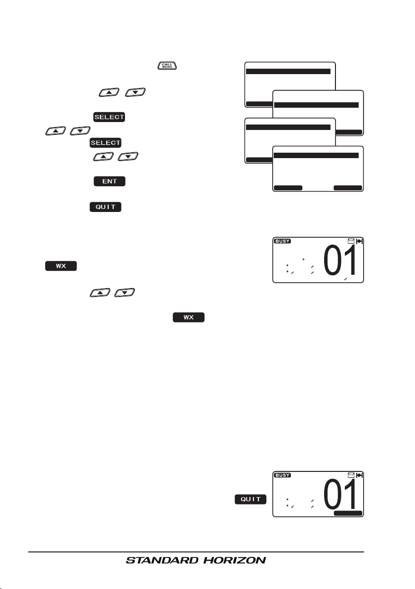
8.7 NOAA WEATHER CHANNELS
12:56
WX
MP
T
N
W
162.550MHz
1. To receive a NOAA weather channel, press the
one of the Soft keys momentarily, then press the
soft key from any channel. The transceiver
will go to the last selected weather channel.
SOG:25.0
COG:123
33 37.120
118 09.580
LOC AM
2. Press the / key to select a different NOAA weather channel.
3. To exit from the NOAA weather channels, press the one of the Soft keys
momentarily, then press the soft key. The transceiver returns to
the channel it was on prior to a weather channel.
8.7.1 NOAA Weather Alert
In the event of extreme weather disturbances, such as storms and hurricanes, the NOAA (National Oceanic and Atmospheric Administration) sends
a weather alert accompanied by a 1050 Hz tone and subsequent weather
report on one of the NOAA weather channels.
The GX1700 can receive weather alerts when on a weather channel and on
the last selected weather channel during scaning modes or while on another
channel.
When an alert is received on a NOAA weather channel, scanning will stop
and the transceiver will emit a loud beep to alert the
user of a NOAA broadcast. Pess any key to stop the
alert and receive the weather report. Press the
key to return to the last selected channel.
WEATHER
ALERT
33 37.120
118 09.580
To disable the Weather Alert function, refer to section “11.6 WEATHER
ALERT”.
WX
N
W
QUIT
GX1700Page 30
 Loading...