

Standard Horizon DS150 Owner's Manual
DS150
Digital Depth Sounder
Owner’s Manual
Marine Division of Vertex Standard

LIMITED WARRANTY
STANDARD HORIZON MARINE DIVISION OF VERTEX STANDARD warrants to the original purchaser
that each new Marine Product manufactured and/or supplied by STANDARD HORIZON will be free from
defects in materials and workmanship under conditions of normal use and service for a period of one
(1) year from the date of delivery to the Purchaser. STANDARD HORIZON’s liability under this
warranty shall be limited to repair or replacement of the defective product, at STANDARD HORIZON’s
option, under no circumstances shall STANDARD HORIZON be liable for consequential, incidental, or
other damages arising out of or in any way connected with a failure of the product to perform as set forth
herein.
In the event of a defect, malfunction, or failure of the product to conform to specifications during the
one-year warranty period, STANDARD HORIZON will repair or replace, at its option and without charge
to the Purchaser, the product which upon examination by STANDARD HORIZON shall appear to be
defective or not up to factory specifications. To obtain warranty service, the defective product must be
returned to STANDARD HORIZON together with proof of the date of purchase. The Purchaser must pay
any transportation expenses in returning the product to STANDARD HORIZON. STANDARD HORIZON
will examine the product and respond to the Purchaser in approximately four (4) weeks from date of
receipt of the product claimed to be defective.
This limited warranty does not extend to any product which has been subjected to misuse, neglect,
accident, improper installation, or subject to use in violation of the maintenance or operating instructions,
if any, furnished by STANDARD HORIZON, nor does this warranty extend to products on which the
serial number has been removed, defaced, or changed. STANDARD HORIZON reserves the right to
make changes or improvements to its products without notice during subsequent production without
incurring the obligation to install such changes or improvements on previously manufactured or sold
products.
To receive warranty service, the Purchaser must deliver the product, transportation and insurance
prepaid, to STANDARD HORIZON Marine Division of Vertex Standard, 115 North Wright Brothers
Dr. Salt Lake City, Utah 84116-2838. Include proof of purchase and date of purchase. STANDARD
HORIZON will return the Product to the Purchaser freight prepaid.
Some states do not allow limitations on the duration of the warranty or exclusions or limitations of
incidental or consequential damages so these limitations or exclusions may not apply to you. This
warranty gives you specific legal rights, which may vary from state to state.
Lifetime Flat Rate Service Program: For the original Purchaser only, for the lifetime of the unit,
STANDARD HORIZON will repair the unit to original specifications.
Note: The flat rate amount is payable by the Purchaser only if STANDARD HORIZON determines that
a repair is needed. After the repair, a 90-day warranty will be in effect from the date of return of the unit
to the Purchaser.
Owner’s Records
Model Serial number
Purchase date Dealer

Contents
1 General Information ............................................................................................ 4
1.1 Introduction ................................................................................................. 4
2 Controls and connections .................................................................................. 4
1.2 Front panel ................................................................................................. 4
1.3 Rear panel.................................................................................................. 4
3 Accessories ........................................................................................................ 5
3.1 Optional ...................................................................................................... 5
3.2 Replacement Parts .................................................................................... 5
4 Installation ........................................................................................................... 5
4.1 Instrument Installation ............................................................................... 5
4.1.1 Location.............................................................................................................. 5
4.1.2 Mounting ............................................................................................................. 5
4.1.3 Wiring Connection .............................................................................................. 6
4.1.4 Multiple Instruments ........................................................................................... 6
4.2 Transducer Installation.............................................................................. 7
4.2.1 In-Hull Installation ................................................................................................ 7
5 Operation ............................................................................................................ 7
5.1 Primary Functions ...................................................................................... 7
5.1.1 Select Units ........................................................................................................ 7
5.1.3 Setting Alarms .................................................................................................... 8
5.1.3.1 Set Shallow Alarm .......................................................................................... 8
5.1.3.2 Set Deep Alarm ............................................................................................... 8
5.1.4 Depth Alarm On / Off ......................................................................................... 8
5.2 Secondary Functions ................................................................................. 8
5.2.1 Set Display Dampening ...................................................................................... 8
5.2.2 Keel Offset ......................................................................................................... 9
5.2.3 Turbulence Setting ............................................................................................. 9
5.2.4 Simulation Mode ................................................................................................. 9
5.3 Microprocessor Reset ............................................................................. 10
6 Maintenance ...................................................................................................... 10
7 Specifications ................................................................................................... 11
8 Troubleshooting ............................................................................................... 11
DS150 User Manual Page 3
Owner’s Manual

1 General Information
Note: Please familiarize yourself with the entire manual and transducer installation guide before
attempting installation.
1.1 Introduction
The DS150 is a high quality digital depth sounder. It
mounts into a 1¼ inch diameter instrument hole on
the bulkhead.
Features include depth readings from 3 to 400 feet
(equivalent meters or fathoms can be selected),
adjustable deep and shallow alarms with audible
alert, and waterproof front panel that can withstand
direct water spray. The unit will display “--” if the
depth is below 3 feet, above 400 feet, or if the
transducer signal is interrupted by cavitation.
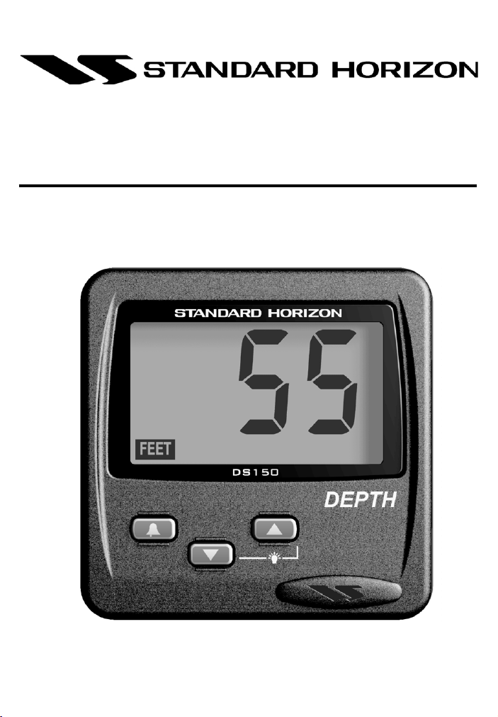
1.2 Front panel
The front panel includes a large 3 1/2-digit LCD and
three-button keypad. The keypad uses both tactile
and audible feedback to indicate when a key is
pressed. All functions are controlled entirely by
these three keys.
1.3 Rear panel
The rear panel contains an RCA phono connector
for connection to the transducer. It also contains
red and black wires for connection to the power
supply and a blue wire for NMEA output.
Included:
• Owners manual
• DS150 Digital instrument
• DS150 Panel Gasket
• DC150 Dust cover
2 Controls and connections
Display is backlit for
Night Operation
Indicate depth units
Alarm On/Off
Change Value Down
Page 4
Figure 1. DS150 Front Panel
Owner’s Manual
Depth is increasing
Indicates alarm is on
Depth is decreasing
Deep Alarm
Set/Indicator
Shallow Alarm
Set/Indicator
Change Value Up
DS150 User Manual
 Loading...