

Demonstration board: multipower ballast for T5 fluorescent
tube lamps based on the ST7LIT19BF1 and STP5NK60Z
Features
■ Improved efficiency
■ Increased lamp life
■ Lightweight with smaller dimensions
■ Better lamp power control
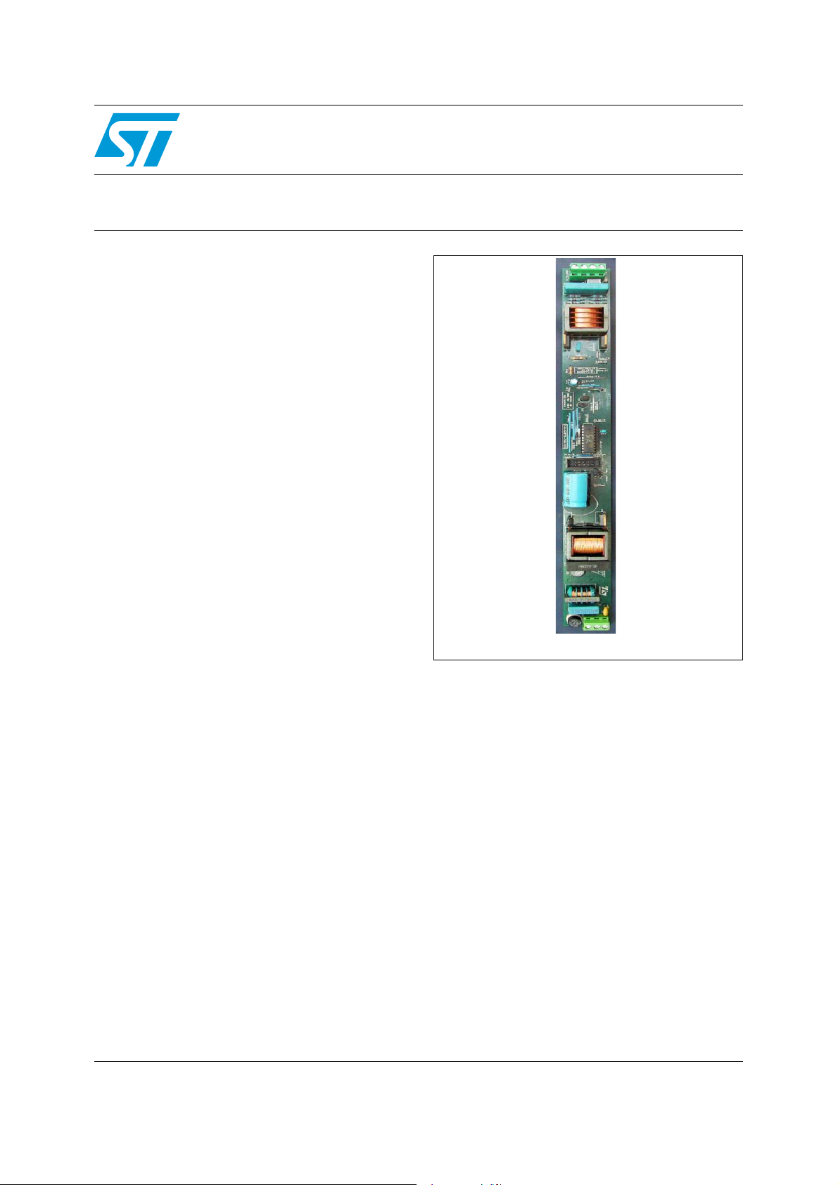
Description
The STEVAL-ILB004V1 demonstration board is
an electronic ballast that adds “intelligence” to
ballast circuits, thanks to the use of a
microcontroller. Rather than having a dedicated
circuit for each tube lamp with a single ballast, the
STEVAL-ILB004V1 can drive many different lamp
groups. The system is capable of recognizing T5type fluorescent lamps, with power ratings of 24
W, 39 W, 54 W and 80 W. It consists of two main
blocks: a boost converter (power factor controller)
working in transition mode (fixed TON and
variable frequency), and an inverter in half-bridge
configuration working in zero-voltage switching.
Both the ballast and PFC stages are controlled by
the ST7LIT19BF1 microcontroller, which provides
its signal to the L6382D5 power management
unit. The power management unit delivers the
right voltage and current levels to the
STP5NK60Z power MOSFET. After tube
recognition, the system sets the parameters to
drive the lamp correctly.
STEVAL-ILB004V1
Data Brief
STEVAL-ILB004V1
December 2008 Rev 1 1/4
For further information contact your local STMicroelectronics sales office.
www.st.com
4
Schematic diagram STEVAL-ILB004V1
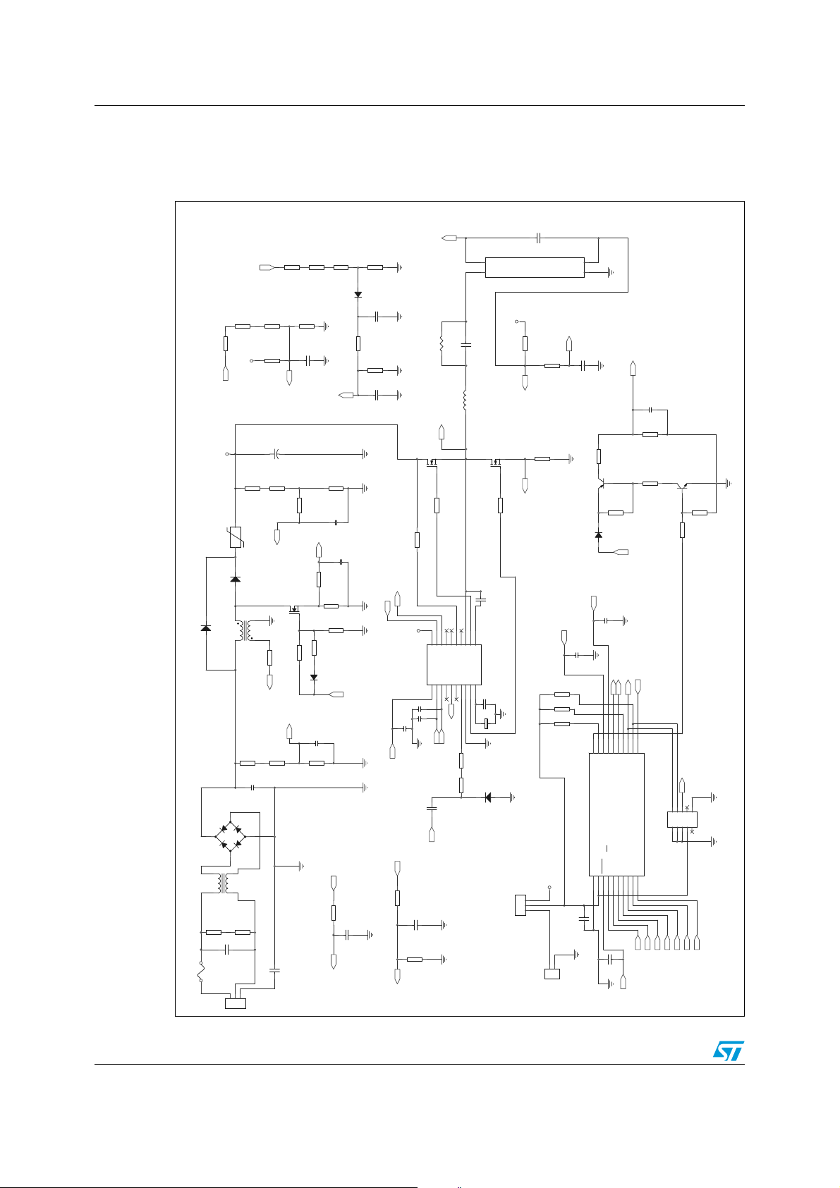
1 Schematic diagram
Figure 1. Electrical schematic
C16
10n
DC5V
R29
LampTypeDetection Circuit
R21 10
RsenseCurrent
3
2
1
jump-prog/run
T5 Lamps
1M
R2312W,1%
J5
1600V
R30
10k
PFC Zero Current Detect
10k
R45
10k
R44
10k
R43
DC5V
1
2
VDC-5V-programm.
J2
LampPresence
C17
10n
C28
10p
U1
C9
220nF
4
R54
10k
Q4
BF421
R47
47k
D14
STTH1L06
CSO
C14
10n
High Side Input
Low Side Input
17
14
15
16
20
19
18
OSC2/PC1
PA0(HS)/LTIC
PA1(HS)/ATIC
PA4(HS)/ATPWM2
PA3(HS)/ATPWM1
PA2(HS)/ATPWM0
OSC1/CLKIN/PC0
Vdd2RESET3COMPIN+/SS/AIN0/PB0
SCK/AIN1/PB15MISO/AIN2/PB26MOSI/AIN3/PB37COMP-/CLKIN/AIN4/PB4
Vss
1
4
10nF
C10
RESET
LampTypeDetection
C30
330n
R48
3.3k
R49
10k
LampTypeDetection Circuit
PFC Gate Driver
LampPresence
11
12
13
ST7LITE1B 20pin
PA7(HS)/COMPOUT
PA6/MCO/ICCCLK/BREAK
PA5(HS)/ATPWM3/ICCDATA
J3
AIN5/PB59AIN6/PB6
8
10
PFC OC
AverageCurrent
PFC Vout Sense
PFC VinWaveform
Q5
BF420
R51
47k
R52
1.8k
Lamp Type Detection Circuit Enable
RESET
10
+2+4+6+8+
+1+3+5+7+
9
ICC-programmer
PeakLampVoltage
LampTypeDetection
AverageLampVoltage
Vcap
R31
330k
R32
330k
R33
330k
R34
D6
R35
PeakLampVoltage
10k
4n7
2n7
C5
47k
PFC Mosfet Gate
10k
C22
470n
120k
1N4148 SMD
C19
75k
R36
22k
C23
68n
4n7
100V
CSI
R27
R18
CSO
C27
10p
PFC Gate Driver
RsenseCurrent
3k9
C20
R28
CSI
R53
Q2
STP6NK60Z
R19 10
00.6W
DC5V
19
20
CSI
VREF
U2
PFI1LSI2HSI3HEI4PFG5NC6TPR7GND8LSG9VCC
C25
10p
C26
10p
Low Side Input
C8
Out pin
1n
820
Vcap
R38
220k
R39
220k
R40
2k2
R37
220k
R41
2k2
DC5V
Vcap
DC400V
R11
750k
NTC1
10
1 2
D2
STTH1L06
1 2
35
D12
1N4007
2.0mH
81
2 1
T2
R3
750k
C3
470n 275VAC
3
D7
BRIDGE RB156
4
R11M350V
F1
FUSE
1
2 4
T1
1 3
C1
220n
275VAC
L
N
J1
2
-+
2x47mH
R21M350V
AC
PE
AverageLampVoltage
C7
22uF 450V
+
R12
750k
R14
PFC Vout Sense
STP6NK60Z
23
Q1
R7
27k
R6
PFC VinWaveform
PFC Zero Current Detect
R4
750k
C21n275VAC
C18
470n
R13
1k
C6
PFC OC
1k
R10
R9
0.5
1
R8
10
R22 33
D4
100p
C4
R5
18k
RsenseCurrent
R24
AverageCurrent
23
1
C15
100nF
L1
Out pin
14
16
15
NC
HEG17CSO
HVSU
PFC Mosfet Gate
R46
High Side Input
R16
1nF
630V
400V
1.2mH
Q3
100nF
C13
50V
12
13
11
NC
OUT
HSG
BOOT
L6382
10
C12
100nF
C11
47uF
35V
+
220.6W
220.6W
D13
STTH1L06A
1M
18
STP6NK60Z
2 1
J4
2/4

STEVAL-ILB004V1 Revision history
2 Revision history
Table 1. Document revision history
Date Revision Changes
02-Dec-2008 1 Initial release.
3/4

STEVAL-ILB004V1
y
Please Read Carefully:
Information in this document is provided solely in connection with ST products. STMicroelectronics NV and its subsidiaries (“ST”) reserve the
right to make changes, corrections, modifications or improvements, to this document, and the products and services described herein at any
time, without notice.
All ST products are sold pursuant to ST’s terms and conditions of sale.
Purchasers are solely responsible for the choice, selection and use of the ST products and services described herein, and ST assumes no
liability whatsoever relating to the choice, selection or use of the ST products and services described herein.
No license, express or implied, by estoppel or otherwise, to any intellectual property rights is granted under this document. If any part of this
document refers to any third party products or services it shall not be deemed a license grant by ST for the use of such third party products
or services, or any intellectual property contained therein or considered as a warranty covering the use in any manner whatsoever of such
third party products or services or any intellectual property contained therein.
UNLESS OTHERWISE SET FORTH IN ST’S TERMS AND CONDITIONS OF SALE ST DISCLAIMS ANY EXPRESS OR IMPLIED
WARRANTY WITH RESPECT TO THE USE AND/OR SALE OF ST PRODUCTS INCLUDING WITHOUT LIMITATION IMPLIED
WARRANTIES OF MERCHANTABILITY, FITNESS FOR A PARTICULAR PURPOSE (AND THEIR EQUIVALENTS UNDER THE LAWS
OF ANY JURISDICTION), OR INFRINGEMENT OF ANY PATENT, COPYRIGHT OR OTHER INTELLECTUAL PROPERTY RIGHT.
UNLESS EXPRESSLY APPROVED IN WRITING BY AN AUTHORIZED ST REPRESENTATIVE, ST PRODUCTS ARE NOT
RECOMMENDED, AUTHORIZED OR WARRANTED FOR USE IN MILITARY, AIR CRAFT, SPACE, LIFE SAVING, OR LIFE SUSTAINING
APPLICATIONS, NOR IN PRODUCTS OR SYSTEMS WHERE FAILURE OR MALFUNCTION MAY RESULT IN PERSONAL INJURY,
DEATH, OR SEVERE PROPERTY OR ENVIRONMENTAL DAMAGE. ST PRODUCTS WHICH ARE NOT SPECIFIED AS "AUTOMOTIVE
GRADE" MAY ONLY BE USED IN AUTOMOTIVE APPLICATIONS AT USER’S OWN RISK.
Resale of ST products with provisions different from the statements and/or technical features set forth in this document shall immediately void
any warranty granted by ST for the ST product or service described herein and shall not create or extend in any manner whatsoever, an
liability of ST.
ST and the ST logo are trademarks or registered trademarks of ST in various countries.
Information in this document supersedes and replaces all information previously supplied.
The ST logo is a registered trademark of STMicroelectronics. All other names are the property of their respective owners.
© 2008 STMicroelectronics - All rights reserved
STMicroelectronics group of companies
Australia - Belgium - Brazil - Canada - China - Czech Republic - Finland - France - Germany - Hong Kong - India - Israel - Italy - Japan -
Malaysia - Malta - Morocco - Singapore - Spain - Sweden - Switzerland - United Kingdom - United States of America
www.st.com
4/4
 Loading...