


 Loading...
VEHICLE GENERAL
0000-00
VEHICLE GENERAL
VEHICLE GENERAL |
|
1. DIMENSIONS........................................ |
3 |
2. SPECIFICATIONS................................. |
4 |
3. VEHICLE IDENTIFICATION................... |
6 |
4. MAINTENANCE .................................... |
7 |
5. RECOMMENDED FLUIDS AND |
|
LUBRICANTS........................................ |
13 |
6.JACK-UP POINTS (DOTTED CIRCLES). 14
7.PIN ARRANGEMENT OF DIAGNOSTIC
CONNECTOR........................................ |
15 |
8. ELECTRIC COMPONENTS AND |
|
LAYOUT................................................ |
16 |
9. TIGHTENING TORQUE OF |
|
STANDARD BOLTS............................... |
18 |
|
0000-00 |
01-3 |
|
|||
VEHICLE GENERAL |
|
|
0000-00 |
|
|
|
|
|
|||||
|
||||||
GENERAL
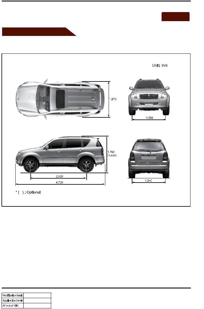
1. DIMENSIONS
VEHICLE GENERAL
undefined

01-4 0000-00
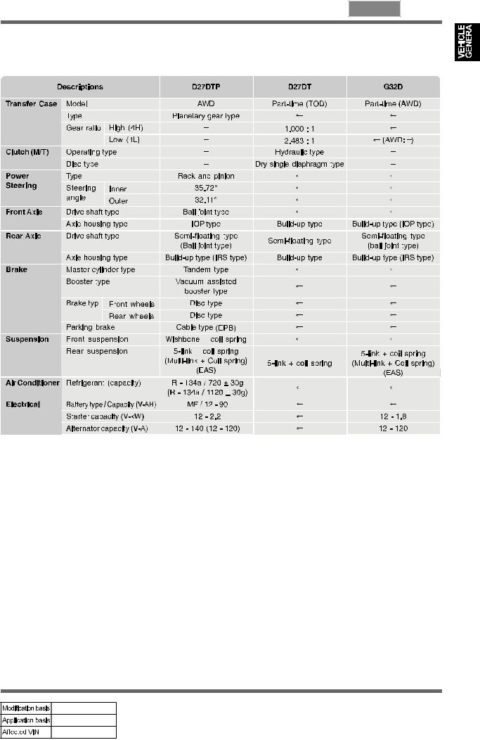
2. SPECIFICATIONS
* ( |
): Optional, [ |
]: 2WD, < >: DPF |
D27DTP: Diesel 2.7 Power-Up, D27DT: Diesel 2.7, G32D: Gasoline |
||
VEHICLE GENERAL
undefined
0000-00 01-5
Specifications (Cont'd)
VEHICLE GENERAL
undefined
01-6 0000-00
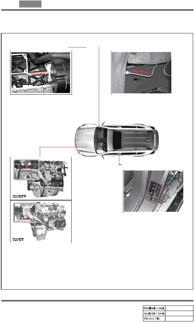
3. VEHICLE IDENTIFICATION
1. Engine Number |
2. Chassis Number |
Gasoline Engine: The engine number is stamped on the lower area of cylinder block in exhaust manifold side.
The chassis number is stamped on the frame behind the front right tire.
Diesel Engine (D27DTP, D27DT): The engine number is stamped on the lower area of cylinder block behind the Intake manifold.
VEHICLE GENERAL
undefined
3. Certification Label
The certification label is located on the driver's door sill.
0000-00 01-7
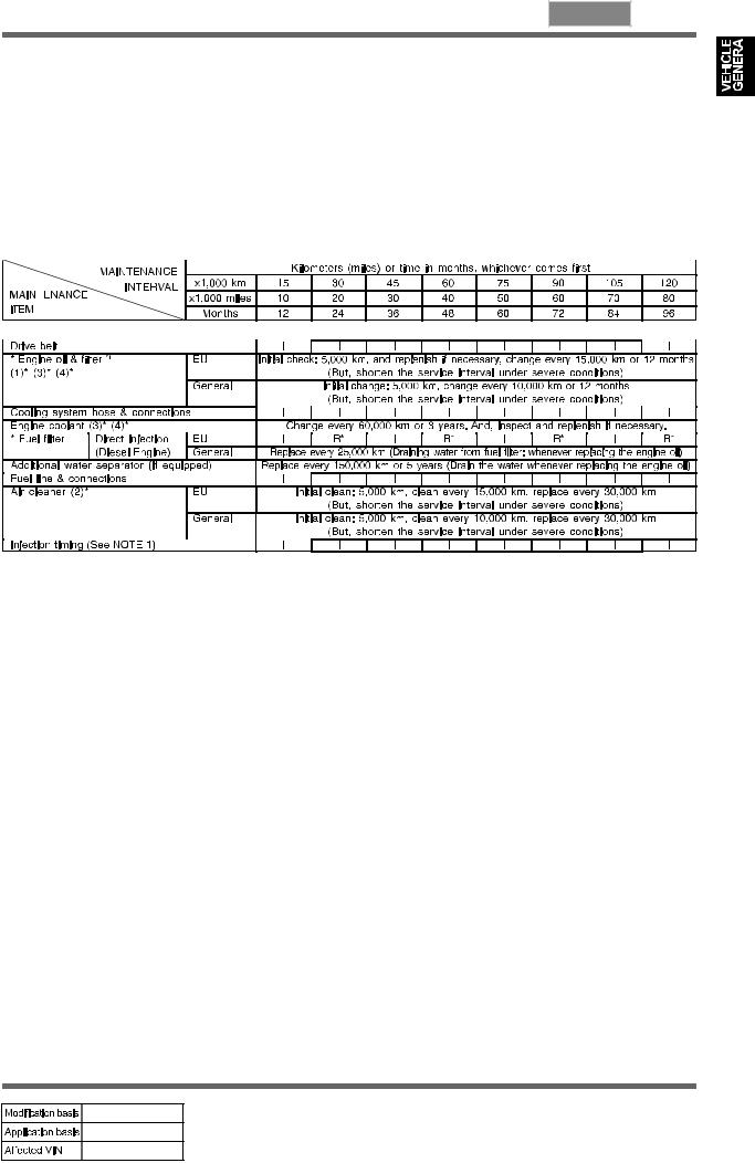
4. MAINTENANCE
1) Diesel Engine |
* Use only approved Ssangyong genuine parts. |
Maintenance service and record retention are the owner's responsibility. You should retain evidence that proper maintenance has been performed on your vehicle in accordance with the scheduled maintenance service chart.
* EU Countries: Only countries that belong to EU. (It does not apply to all countries in EU.)
ENGINE CONTROL SYSTEM
NOTE 1: Adjust as required;
-When excessive smoke is visible (black or white)
-Poor performance/economy
Chart Symbols:
I - Inspect these items and their related parts. If necessary, correct, clean, replenish, adjust or replace. *1 Check the engine oil level and leak every 3,000 km (2,000 miles) or before starting a long trip.
R - Replace or change.
(1)* If vehicle is operated under severe condition: Shorten the service interval.
-Frequent stop-and-go traffic, extended idling, short driving distance below 6 km, driving distance below 16 km when the outside temperature remains below freezing
-Driving in a hilly or mountainous terrain, sandy, or dusty area
-High load driving such as trailer towing
-Taxi, patrol service or delivery service (extended idling and excessive driving with low speed) (2)* If vehicle is operated under severe condition, driving in dusty condition or sandy condition,
pollutant area or off-road driving, frequently inspect the air cleaner, if necessary, change the air cleaner.
(3)* More frequent maintenance is required if under dusty driving condition.
(4)* Refer to ecommended fluids, coolant and lubricants?
*Water separator: When replace the engine oil, also drain the water from the fuel filter.
VEHICLE GENERAL
undefined

01-8 0000-00
* EU Countries: Only countries that belong to EU. (It does not apply to all countries in EU.)
CHASSIS AND BODY
Chart Symbols:
I - Inspect these items and their related parts. If necessary, correct, clean, replenish, adjust or replace.
R - Replace or change.
(3)* Refer to "Recommended fluids and lubricants".
(4)* More frequent maintenance is required if the vehicle is operated under any of the following conditions:
- In heavy city traffic where the outside temperature regularly reaches 32°C (90°F) or higher, or
-In hilly or moutainous terrain, or
-When doing frequent trailer towing, or
-Uses such as found in taxi, police or delivery service.
(5)* Inspect manual transmission fluid every 15,000 km (Inspect the leak of fluid at any time,occasionally), then change every 60,000 km
(6)* Change automatic transmission fluid and every 60,000 km if the vehicle is mainly driven under severe conditions: Towing a trailer or off-road driving (Inspect the leak of fluid at any time, occasionlly)
VEHICLE GENERAL
undefined
0000-00 01-9
* Use only approved Ssangyong genuine parts.
CHASSIS AND BODY
Chart Symbols:
I - Inspect these items and their related parts. If necessary, correct, clean, replenish, adjust or replace.
R - Replace or change.
(3)* Refer to "Recommended fluids and lubricants".
(6)* After completion of off-road operation, the underbody of the vehicle should be throughly inspected. Examine threaded fasteners for looseness.
(7)* If necessary, rotate and balance wheels.
(8)* After completion of off-road operation, the drive shaft boots should be inspected. (9)* Inspect propeller shaft grease every 5,000 km or 3 months if the vehicle is mainly
driven under severe condition.
-In off-road or dusty road, or
-In heavy city traffic where the outside temperature regularly reaches 32°C (90°F) or higher, or
-In hilly or moutainous terrain.
Severe Conditions in Air Conditioner Filter
- Pollutant area or off-road driving, extended air conditioner or heater operation
VEHICLE GENERAL
undefined

01-10 0000-00
2) Gasoline Engine |
* Use only approved Ssangyong genuine parts. |
Maintenance service and record retention are the owner's responsibility. You should retain evidence that proper maintenance has been performed on your vehicle in accordance with the scheduled maintenance service chart.
* EU Countries: Only countries that belong to EU. (It does not apply to all countries in EU.)
ENGINE CONTROL SYSTEM
Chart Symbols:
I - Inspect these items and their related parts. If necessary, correct, clean, replenish, adjust or replace. R - Replace or change.
**- In order to secure engine long life and effective break-in, first oil (factory filled) would be recommended to drain with in 10,000 km.
(1)* If vehicle is operated under severe condition: short distance driving, extensive idling or driving in dusty condition, shorten the service interval.
(2)* If vehicle is operated under severe condition, pollutant area or off-road driving, driving in dusty condition or sandy condition, frequently inspect the air cleaner, if necessary, change the air cleaner.
(3)* Refer to "Recommended fluids and lubricants".
VEHICLE GENERAL
undefined
0000-00 01-11
* EU Countries: Only countries that belong to EU. (It does not apply to all countries in EU.)
CHASSIS AND BODY
Chart Symbols:
I - Inspect these items and their related parts. If necessary, correct, clean, replenish, adjust or replace.
R - Replace or change.
(3)* Refer to "Recommended fluids and lubricants".
(4)* More frequent maintenance is required if the vehicle is operated under any of the following conditions:
- In heavy city traffic where the outside temperature regularly reaches 32°C (90°F) or higher, or
-In hilly or moutainous terrain, or
-When doing frequent trailer towing, or
-Uses such as found in taxi, police or delivery service.
(5)* Inspect manual transmission fluid every 15,000 km (Inspect the leak of fluid at any time,occasionally), then change every 60,000 km
(6)* Change automatic transmission fluid and every 60,000 km if the vehicle is mainly driven under severe conditions: Towing a trailer or off-road driving (Inspect the leak of fluid at any time, occasionlly)
VEHICLE GENERAL
undefined

01-12 0000-00
* EU Countries: Only countries that belong to EU. (It does not apply to all countries in EU.)
CHASSIS AND BODY
Chart Symbols:
I -Inspect these items and their related parts. If necessary, correct, clean, replenish, adjust or replace.
R - Replace or change.
(3)* Refer to "Recommended fluids and lubricants".
(6)* After completion of off-road operation, the underbody of the vehicle should be throughly inspected. Examine threaded fasteners for looseness.
(7)* If necessary, rotate and balance wheels.
(8)* Inspect propeller shaft grease every 5,000 km or 3 months if the vehicle is mainly driven under severe condition.
-In off-road or dusty road, or
-In heavy city traffic where the outside temperature regularly reaches 32°C (90°F) or higher, or
-In hilly or moutainous terrain.
Severe Conditions in Air Conditioner Filter
- Pollutant area or off-road driving, extended air conditioner or heater operation
VEHICLE GENERAL
undefined
0000-00 01-13
5. RECOMMENDED FLUIDS AND LUBRICANTS
-Use only Ssangyong recommended fluids and lubricants.
-Keep the specified levels when adding or replacing the fluids.
-Do not mix any different types or brands of oils or fluids. This may cause damages.
D27DTP: Diesel 2.7 Power-Up
D27DT: Diesel 2.7
G32D: Gasoline
VEHICLE GENERAL
undefined
01-14 0000-00
6. JACK-UP POINTS (DOTTED CIRCLES)
IRS type
5-link type
VEHICLE GENERAL
undefined
0000-00 01-15
7. PIN ARRANGEMENT OF DIAGNOSTIC CONNECTOR
It is installed under the instrument panel and consists of 16 pins.
The REKES key coding should be performed with SCAN-TOOLS.
Diagnostic connector
Functions of Terminal
VEHICLE GENERAL
undefined

01-16 0000-00
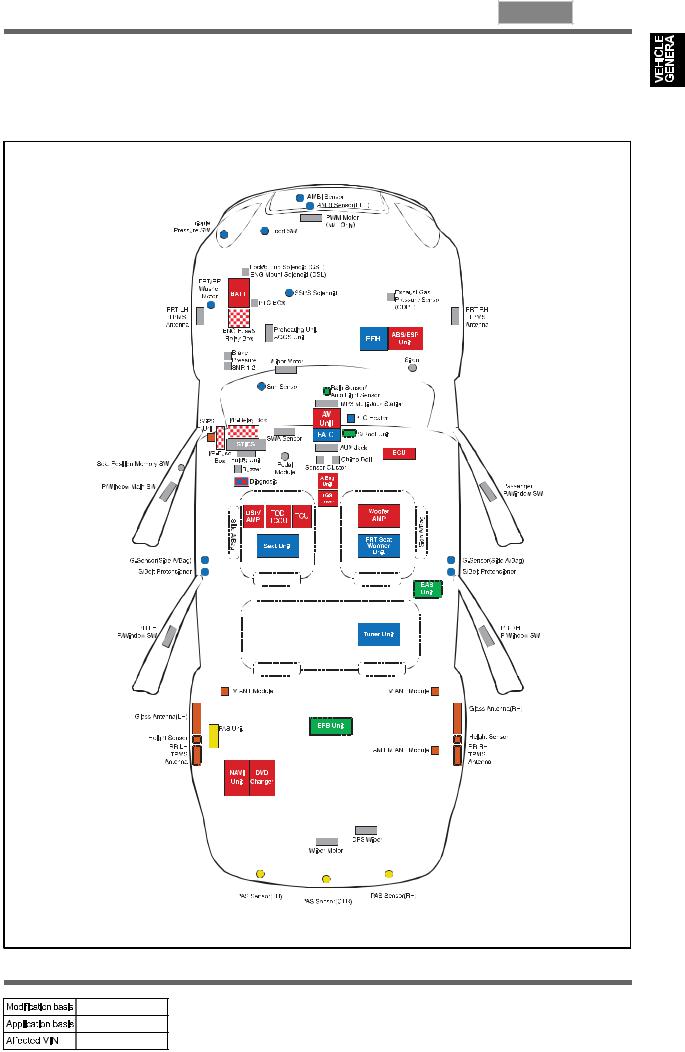
8. ELECTRIC COMPONENTS AND LAYOUT
1) Wiring Harness Arrangement
VEHICLE GENERAL
undefined
0000-00 01-17
2) Components Locator
VEHICLE GENERAL
undefined
01-18 0000-00
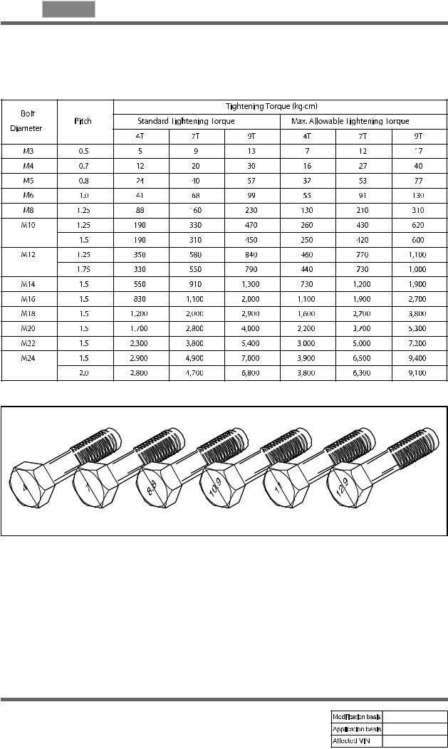
9. TIGHTENING TORQUE OF STANDARD BOLTS
Tightening Torque By Bolt Specification
1.Metric bolt strength is embossed on the head of each bolt. The strength of bolt can be classified as 4T, 7T, 8.8T, 10.9T, 11T and 12.9T in general.
2.Observe standard tightening torque during bolt tightening works and can adjust torque to be proper within 15 % if necessary. Try not to over max. allowable tightening torque if not required to do so.
VEHICLE GENERAL
REXTON 2008.01
3.Determine extra proper tightening torque if tightens with washer or packing.
4.If tightens bolts on the below materials, be sure to determine the proper torque.
·Aluminum alloy: Tighten to 80 % of above torque table.
·Plastics: Tighten to 20 % of above torque table.
|
1113-01 |
01-3 |
|
|||
ENGINE ASSEMBLY |
|
|
1113-01 |
|
|
|
|
|
|||||
|
||||||
GENERAL
1. DESCRIPTION AND OPERATION
1) Cleanliness and Care
An automobile engine is a combination of many machined, honed, polished and lapped surfaces with tolerances that are measured in the ten-thousanths of an inch.
When any internal engine parts are serviced, care and cleanliness are important.
A liberal coating of enigne oil should be applied to friction areas during assembly, to protect and lubricate the surfaces on initial operation. Proper cleaning and protection of machined surfaces and friction areas is part of the repair procedure.
This is considered standard shop practice even if not specifically stated.
Whenever valve train components are removed for service, they should be kept in order. They should be installed in the same locations, and with the same mating surfaces, as when they were removed.
Battery cables should be disconnected before any major work is performed on the engine. Failure to disconnect cables may result in damage to wire harness or other electrical parts.
ENGINE ASSEMBLY
REXTON 2008.01

01-4 1113-01
2)On-engine Service
-Disconnect the negative battery cable before removing or installing any electrical unit, or when a tool or equipment could easily come in contact with exposed electrical terminals. Disconnecting this cable will help prevent personal injury and damage to the vehicle. The ignition must also be in LOCK unless otherwise noted.
-Any time the air cleaner is removed, the intake opening should be covered. This will protect against accidental entrance of foreign material, which could follow the intake passage into the cylinder and cause extensive damage when the engine is started.
ENGINE ASSEMBLY
REXTON 2008.01
1113-01 01-5
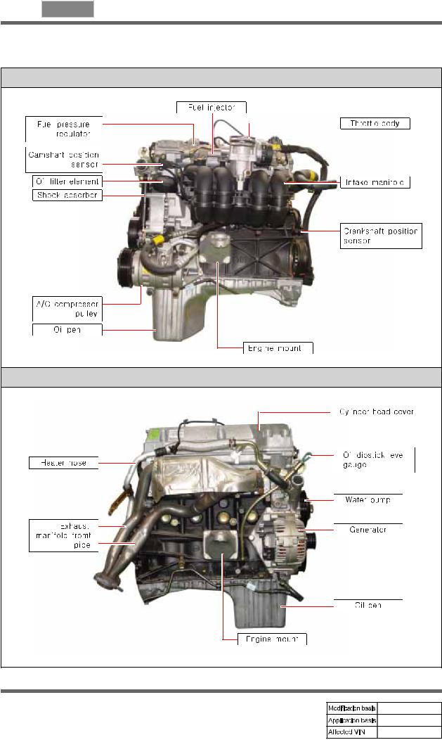
2. G23D ENGINE ASSEMBLY
Front View |
Rear View |
ENGINE ASSEMBLY
REXTON 2008.01
01-6 1113-01
LH Side View
RH Side View
ENGINE ASSEMBLY
REXTON 2008.01
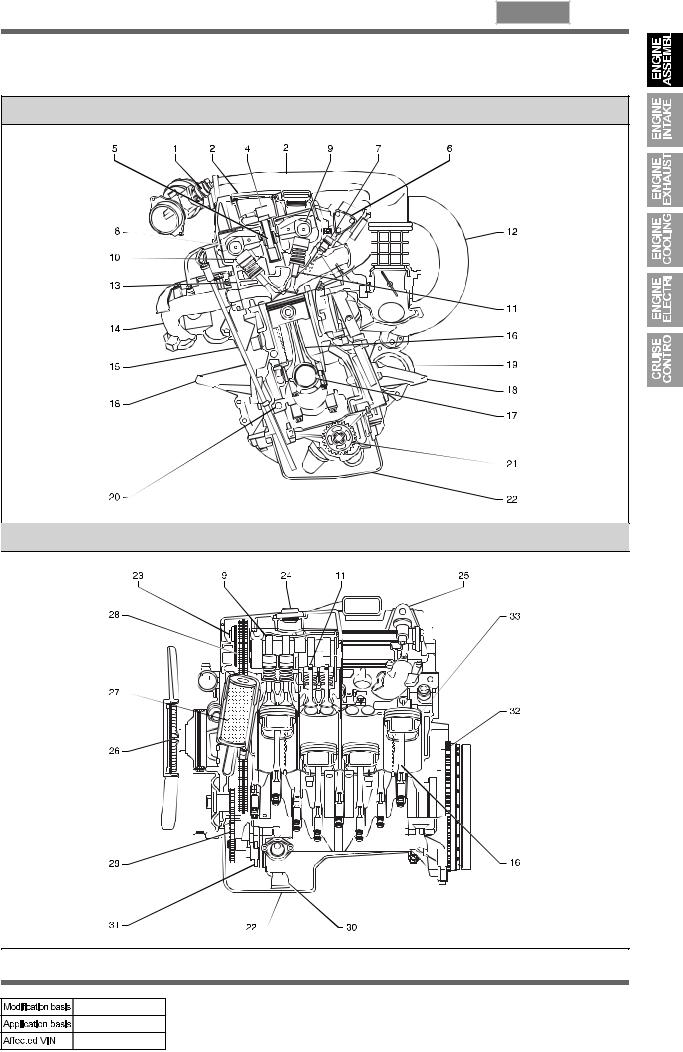
1113-01 01-7
3. G23D ENGINE STRUCTURE
Front View
Side View
ENGINE ASSEMBLY
REXTON 2008.01
01-8 1113-01
Front View
NO. |
FUNCTION |
NO. |
FUNCTION |
|
|
|
|
1 |
HFM Sensor |
12 |
Intake Manifold |
|
|
|
|
2 |
Intake Air Duct |
13 |
Cylinder Head |
|
|
|
|
3 |
Cylinder Head Cover |
14 |
Exhaust Manifold |
|
|
|
|
4 |
Ignition Coi |
15 |
Dipstick Guide Tube and Gauge |
|
|
|
|
5 |
Spark Plug Connector |
16 |
Connecting Rod |
|
|
|
|
6 |
Fuel Distributor |
17 |
Crankshaft |
|
|
|
|
7 |
Injector |
18 |
Engine Mounting Bracket |
|
|
|
|
8 |
Exhaust Camshaft |
19 |
Starter |
|
|
|
|
9 |
Intake Camshaft |
20 |
Crankcase |
|
|
|
|
10 |
Valve Tappet |
21 |
Oil Pump Sprocket |
|
|
|
|
11 |
Intake Valve |
22 |
Oil Pan |
|
|
|
|
Side View
NO. |
FUNCTION |
NO. |
FUNCTION |
|
|
|
|
23 |
Camshaft Adjuster |
29 |
Oil Pump Drive Chain |
|
|
|
|
24 |
Oil Filler Cap |
30 |
Oil Strainer |
|
|
|
|
25 |
Engine Hanger Bracket |
31 |
Oil Pump |
|
|
|
|
26 |
Cooling Fan and Viscous Clutch |
32 |
Ring Gear and Flywheel of Drive Plate |
|
|
|
|
27 |
Oil Filter |
33 |
Piston |
|
|
|
|
28 |
Timing Chain |
|
|
|
|
|
|
ENGINE ASSEMBLY
REXTON 2008.01

1113-01 01-9
4. DIAGNOSTIC INFORMATION AND PROCEDURE
1) Oil Leak Diagnosis
Most fluid oil leaks are easily located and repaired by visually finding the leak and replacing or repairing the necessary parts. On some occasions a fluid leak may be difficult to locate or repair. The following procedures may help you in locating and repairing most leaks.
Finding the Leak
-Identify the fluid. Determine whether it is engine oil, automatic transmission fluid, power steering fluid, etc.
-Identify where the fluid is leaking from.
·After running the vehicle at normal operating temperature, park the vehicle over a large sheet of paper.
·Wait a few minutes.
·You should be able to find the approximate location of the leak by the drippings on the paper.
-Visually check around the suspected component.
Check around all the gasket mating surfaces for leaks. A mirror is useful for finding leaks in areas that are hard to reach.
-If the leak still cannot be found, it may be necessary to clean the suspected area with a degreaser, steam or spray solvent.
·Clean the area well.
·Dry the area.
·Operate the vehicle for several miles at normal operating temperature and varying speeds.
·After operating the vehicle, visually check the suspected component.
·If you still cannot locate the leak, try using the powder or black light and dye method.
Powder Method
-Clean the suspected area.
-Apply an aerosol-type powder (such as foot powder) to the suspected area.
-Operate the vehicle under normal operating conditoins.
-Visually inspect the suspected component. You should be able to trace the leak path over the white powder surface to the source.
ENGINE ASSEMBLY
REXTON 2008.01

01-10 1113-01
Black Light and Dye Method
A dye and light kit is available for finding leaks, Refer to the manufacturer's directions when using the kit.
-Pour the specified amount of dye into the engine oil fill tube.
-Operate the vehicle normal operating conditions as directed in the kit.
-Direct the light toward the suspected area. The dyed fluid will appear as a yellow path leading to the source.
Repairing the Leak
Once the origin of the leak has been pinpointed and traced back to its source, the cause of the leak must be determined in order for it to be repaired properly.
If a gasket is replaced, but the sealing flange is bent, the new gasket will not repair the leak. The bent flange must be repaired also. Before attempting to repair a leak, check for the following conditions and correct them as they may cause a leak.
Gaskets
-The fluid level/pressure is too high.
-The crankcase ventilation system is malfunctioning.
-The seal bore is damaged (scratched, burred or nicked).
-The seal is damaged or worn.
-Improper installation is evident.
-There are cracks in the components.
-The shaft surface is scratched, nicked or damaged.
-A loose or worn bearing is causing excess seal wear.
ENGINE ASSEMBLY
REXTON 2008.01
1113-01 01-11
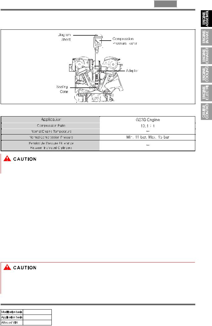
2) Compression Pressure Test
Standard Service Data
- A9912 0012B (001 589 76 21 00) Compression Pressure Tester
Measuring Procedure
-Warm the engine up to normal operating temperature.
-Remove the spark plugs using the spark plug wrench.
-Place the diagram sheet to compression pressure tester A9912 0012B (001 589 76 21 00).
-Connect the adaptor to compression pressure tester A9912 0012B (001 589 76 21 00) and install it into the spark plug hole.
-Crank the engine approx. eight revolutions by using the start motor.
-Compare the measurements of compression pressure tester A9912 0012B (001 589 76 21 00) with the specifications.
-Measure the compression pressure of the other cylinders in the same way.
-If measured value is not within the specifications, perform the cylinder pressure leakage test.
-Discharge the combustion residues in the cylinders before testing the compression pressure.
-Apply the parking brake before cranking the engine.
ENGINE ASSEMBLY
REXTON 2008.01

01-12 1113-01
3) Cylinder Pressure LeakageTest
Permissible Pressure Leakage
At Whole Engine |
Max. 25 % |
|
|
At Valve and Cylinder Head Gasket |
Max. 10 % |
|
|
At Piston and Piston Ring |
Max. 20 % |
|
|
Cylinder Number |
|
|
|
OT (TDC) |
1, 4 |
|
|
UT (BDC 180 °) |
2, 3 |
|
|
Cylinder Number |
|
|
|
Cylinder Pressure |
Bosch, EFAW210A |
Leakage Tester |
Sun, CLT 228 |
|
|
ENGINE ASSEMBLY
REXTON 2008.01
1113-01 01-13
Leakage Test
-Warm the engine up to normal operating temperature.
-Disconnect the negative battery cable.
-Remove the spark plugs.
-Check the coolant level by opening the coolant reservoir cap and replenish if insufficient.
-Open the engine oil filler cap.
-Connect the tester to air pressure line and adjust the scale of tester.
-Install the connecting hose to spark plug hole.
-Position the piston of No.1 cylinder at TDC by rotating the crankshaft.
-Connect the connecting hose to tester and measure the leakage volume after blowing up 5 bar of compressed air.
-Measure the leakage volume in the completely opening condition of throttle valve by pulling the acceleration cable.
-Perform the pressure test according to the firing order.
-Firing Order: 1 - 3 - 4 - 2
-Compare the leakage pressure with the specifications.
ENGINE ASSEMBLY
REXTON 2008.01

01-14 1113-01
5. GENERAL DIAGNOSIS
ENGINE ASSEMBLY
REXTON 2008.01
Loading...