


/ Recold ® JW Series Fluid Cooler /
Engineering Data
Recold / JW Series Fluid Cooler / Contents
2
Construction................................................................................................................ |
3 |
Schematic.................................................................................................................... |
4 |
Engineering Data......................................................................................................... |
5 |
Freeze Protection.......................................................................................................... |
6 |
Selection Procedure...................................................................................................... |
7 |
Load Factors.................................................................................................................. |
8 |
Rating Table................................................................................................................. |
10 |
Pressure Drop............................................................................................................. |
11 |
Accessories................................................................................................................. |
12 |
|
Nomenclature |
|
JW L 50 B |
Design Series |
Unit Size |
Optional GPM Range |
Approximate Coil Face |
L = Low Flow |
(area in sq ft) |
H = High Flow |
|
IMPORTANT
Since Recold heat exchange coils are copper, the coil can be drained without regard to internal corrosion. This must be considered with steel tubes that do not have internal protection.
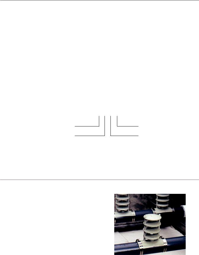
RECOLD HYDROSPRAY
Recold engineering has developed an exclusive water distribution system called hydrospray. This unique system provides optimum water coverage of the heat transfer coil for maximum efficiency and virtual elimination of harmful scale problems that result from uneven water distribution. This process is accomplished through a limited number of large orifice non-clogging diffusers mounted on a heavy duty PVC pipe water header.
Recold / JW Series Fluid Cooler / Construction
3
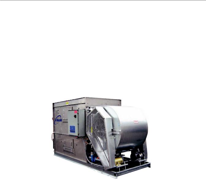
The JW Evaporative Fluid Cooler is a ruggedly built unit constructed to provide many years of durable, dependable service with minimal maintenance requirements. Quality materials and workmanship are a key factor in meeting this objective.
FAN MOTORS
Fan motors furnished as standard equipment are open drip-proof type suitable for outdoor service. Motors have a 1.15 service factor and are mounted on a heavy duty adjustable base located for easy access.
FAN GUARD SCREENS
All moving parts are protected with OSHA approved galvanized steel screens. Each guard is easily removed for access to the fan.
FAN SECTION
The centrifugal fan is forward curved, statically and dynamically balanced and constructed of galvanized steel. The fan housing has curved inlet rings for efficient air entry and discharge into the pan. Fans are mounted on a solid steel shaft coated to resist corrosion. Heavy duty, pillow block type, self-aligning ball bearings are located at each end of the fan shaft.
No intermediate bearings are required
Extended lube lines are
equipment to allow servicing bearings without removal of fan guard screens.
WATER CIRCULATION PUMP
The water circulation pump is a close coupled, bronze fitted centrifugal type with mechanical seal. Each pump is factory mounted and piped. Standard motor is open drip-proof suitable for outdoor service.
DRIFT ELIMINATORS
Eliminators are constructed of PVC assemblies in removable, easy to handle sections. Each section has a three break design allowing three changes in air flow and measure approximately 5 inches in depth. The use of durable PVC eliminates the corrosion problems associated with galvanized eliminators.
HEAT EXCHANGE COIL
Coil tube bundle is constructed of 5⁄8" copper stainless steel tube sheets
headers. The copper construction offers a
noncorrosive coil for extended service life.
ACCESS DOORS
Large rectangular access doors are strategically located to provide access to both upper water distribution system and lower pan basin. The patented doors provide a complete air and water tight seal without the use of gaskets or fasteners
WATER MAKE-UP
Water make-up is provided brass float valve with arm
and float ball installed in an external float b o x . This allows easy observation of the water
operating level and maintenance of the valve with unit in operation.
Construction: The Evaporative Fluid Cooler sump pan is constructed of 300 stainless steel and casing panels are constructed of heavy gauge, G-235 galvanized steel. The sump pan and casing panels are flanged outward so that all the connecting fasteners are located outside the flooded section of the unit to help prevent leaks in the unit and provides a more permanent watertight joint. To provide further protection from corrosion, no
welded joints are located below the water line. The unit is designed for a 30 psf on any projected area and ships in one piece on a minimum 6" high stainless steel channel base to help in handling and installation of the unit.
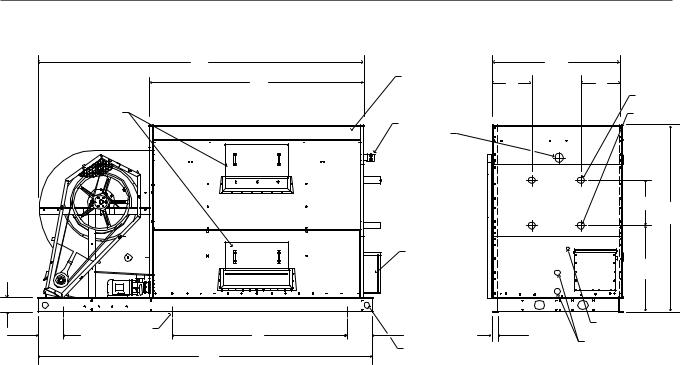
Recold / JW Series Fluid Cooler / Schematic
4
|
|
A |
|
|
C |
|
|
|
K |
ELIMINATOR |
L |
L |
|
|
|
ACCESS |
|
|||
|
ACCESS |
|
|
|
INLET |
|
|
|
|
|
|
|
|
|
DOOR |
|
SPRAY HEADER |
OUTLET |
||
|
|
|
|
|
||
|
|
|
CLEANOUT |
|
|
|
|
|
|
INLET |
|
|
|
|
|
|
CONNECTION |
|
|
|
|
|
|
|
|
G |
B |
|
|
|
OUTLET |
|
|
|
|
|
|
|
|
|
|
|
|
|
CONNECTION |
|
|
|
|
|
|
EXTERNAL |
|
|
|
|
|
|
FLOAT BOX |
|
F |
|
|
|
|
|
|
|
|
J |
|
|
|
|
|
|
12" |
7/8" MOUNTING |
H |
12" |
2" |
WATER SUPPLY Q |
|
|
|
|||||
HOLE (6) |
DRAIN AND |
|
||||
|
|
|
2" LIFTING |
|
|
|
|
|
D |
|
OVERFLOW P |
|
|
|
|
HOLE (4) |
|
|
|
|
|
|
|
|
|
|
|
|
|
|
|
|
Access Doors |
|
Overflow |
Water |
||
Model |
|
|
|
|
Dimensions |
|
|
|
|
Far Side |
Near Side |
Drain |
Supply |
||||
|
|
|
|
|
|
|
|
|
|
FPT |
FPT |
||||||
|
|
|
|
|
|
|
|
|
|
|
|
|
|
|
|||
|
A |
B |
C |
D |
F |
G |
H |
J |
K |
L |
Top |
Bottom |
Top |
Bottom |
P |
Q |
|
|
|
|
|
|
|
|
|
|
|
|
|
|
|
|
|
|
|
JW10 |
80" |
76" |
31" |
84" |
321⁄2" |
191⁄2" |
— |
6" |
53" |
131⁄2" |
1 |
1 |
— |
— |
21⁄2" |
1⁄2" |
|
|
|
|
|
|
|
|
|
|
|
|
|
|
|
|
|
|
|
JW15 |
96" |
76" |
37" |
102" |
311⁄2" |
191⁄2" |
— |
6" |
65" |
16 |
1 |
1 |
— |
— |
21⁄2" |
1⁄2" |
|
|
|
|
|
|
|
|
|
|
|
|
|
|
|
|
|
|
|
JW25 |
1153⁄4" |
77" |
451⁄4" |
124" |
34" |
191⁄2" |
511⁄4" |
6 |
763⁄4" |
201⁄2" |
1 |
1 |
1 |
1 |
21⁄2" |
1⁄2" |
|
note 3 |
|||||||||||||||||
|
|
|
|
|
|
|
|
|
|
|
|
|
|
|
|
||
JW35 |
1391⁄2" |
801⁄4" |
551⁄2" |
144" |
38" |
191⁄2" |
51" |
6" |
92" |
141⁄2" |
1 |
1 |
1 |
1 |
21⁄2" |
3⁄4" |
|
note 3 |
|||||||||||||||||
|
|
|
|
|
|
|
|
|
|
|
|
|
|
|
|
||
JW50 |
1721⁄4" |
921⁄2" |
667⁄8" |
1801⁄4" |
41" |
191⁄2" |
713⁄4" |
6" |
115" |
173⁄8" |
2 |
1 |
2 |
1 |
21⁄2" |
1" |
|
note 3 |
|||||||||||||||||
|
|
|
|
|
|
|
|
|
|
|
|
|
|
|
|
||
JW70 |
1841⁄4" |
981⁄2" |
931⁄4" |
192" |
47" |
191⁄2" |
841⁄2" |
8" |
115" |
note 4 |
2 |
1 |
2 |
1 |
3" |
11⁄4" |
|
note 3 |
|||||||||||||||||
|
|
|
|
|
|
|
|
|
|
|
|
|
|
|
|
||
JW85 |
208" |
981⁄2" |
933⁄8" |
217" |
47" |
191⁄2" |
961⁄2" |
8" |
1391⁄4" |
note 4 |
2 |
1 |
2 |
1 |
3" |
11⁄4" |
|
note 3 |
|||||||||||||||||
|
|
|
|
|
|
|
|
|
|
|
|
|
|
|
|
||
JW100 |
221" |
1181⁄2" |
1001⁄2" |
225" |
67" |
191⁄2" |
80" |
10" |
1391⁄2" |
note 4 |
2 |
2 |
2 |
2 |
4" |
11⁄4" |
|
note 3 |
|||||||||||||||||
|
|
|
|
|
|
|
|
|
|
|
|
|
|
|
|
||
JW115 |
2451⁄2" |
1181⁄2" |
1001⁄2" |
249" |
67" |
191⁄2" |
104" |
10" |
1641⁄2" |
note 4 |
2 |
2 |
2 |
2 |
4" |
11⁄4" |
|
note 3 |
|||||||||||||||||
|
|
|
|
|
|
|
|
|
|
|
|
|
|
|
|
||
JW130 |
269" |
1181⁄2" |
1001⁄2" |
273" |
67" |
191⁄2" |
128" |
10" |
188" |
note 4 |
2 |
2 |
2 |
2 |
4" |
11⁄4" |
|
note 3 |
|||||||||||||||||
|
|
|
|
|
|
|
|
|
|
|
|
|
|
|
|
||
Note
1Use this bulletin for preliminary layouts only. Obtain current drawing from your Recold sales representative.
2If required add 6" for positive closure dampers. If required add 6" for booster coil section.
3An additional bottom access door is installed on the connection end.
4. Consult Recold for coil connection locations.
5If supporting the unit on beams, refer to the Recold suggested supporting steel drawing for required mounting hole location.
 Loading...