


 Loading...
CS4000 Mini Controller with Ethernet
Technical Reference Manual
24-Hour Technical Support Toll Free: 1-877-224-7377
SPX GSE tech-motive tool manufactures products under the GSE and tech-motive tool® brand names.

Please Note:
has a new name. We are now
This change of name is not yet reflected in the documentation for this product where you will still find the old logo and company name. The new address is:
SPX GSE tech-motive tool
42860 Nine Mile Road, Novi MI 48375-4122
The toll free service number remains the same: 1-877-224-7377.
LIMITED WARRANTY
Except for perishable items, such as the fuses and batteries, SPX GSE tech-motive tool warrants its
GSE tech-motive tool brand fastening products, GSE brand sensors and instruments, and fastening systems to be free from defects in materials and workmanship for one year from the date of shipment from the manufacturing facility.
The obligation of SPX GSE tech-motive tool is limited to repairing, or at their option, replacing the products and components which, upon verification at the manufacturing facility in Novi, Michigan USA, prove to be defective. SPX GSE tech-motive tool shall not be liable for installation charges, for expenses of the Buyer for repairs or replacement, for damages from delay or loss of use, or other indirect or consequential damages of any kind. SPX GSE tech-motive tool extends this warranty only upon proper use of the product in the application for which it is intended. The warranty does not cover products that have been modified without the approval of
SPX GSE tech-motive tool or which have been subjected to unusual physical or electrical stress, or from or upon which the original identification marks have been removed or altered.
Whenever the design of the system in which it is to be incorporated originates with the Buyer, the warranty is limited specifically to furnishing the controllers and nutrunners free of defects in materials and workmanship and assumes no responsibility for implied warranties of fitness for purpose or use.
In the event that a product is repaired or replaced under the terms of the warranty, the warranty period of the repaired or replacement product shall be limited by the agreed upon level of warranty purchased by the customer.
Industrial installations are warranted by SPX GSE tech-motive tool for repairs at the installation site only if the customer contracts with SPX GSE tech-motive tool to perform checkout and final adjustment at the installation site and for the training of customer personnel in the operation and maintenance under the system. Under such conditions, SPX GSE tech-motive tool agrees to perform field service for 90 days from date of checkout without charge for labor or materials. The customer shall pay for travel expenses of SPX GSE tech-motive tool personnel.
Warranty of peripheral equipment, such as printers, recorders, plotters, etc., included with a GSE tech-motive tool or GSE torque product or SPX GSE tech-motive tool fastening system, shall be extended to the Buyer on the original manufacturer’s terms.
Transportation charges for materials shipped to the manufacturing facility for warranty repair are to be paid by the shipper. SPX GSE tech-motive tool will return items repaired or replaced under warranty prepaid.
Information and technical diagrams in this document are subject to change without notice. Products and services referred to in this book may be either trademarks and/or registered trademarks of their respective owners.
SPX GSE tech-motive tool manufactures products under the GSE and tech-motive tool® brand names in Novi, MI.
© 2002 SPX CORPORATION. ALL RIGHTS RESERVED.
Acknowledgments
Special thanks are extended to the following SPX GSE tech-motive tool management, software and hardware engineers who provided value information in the development and review of this manual.
Jim Grenier
Tom Jozwiak
Ken Lehoczky
Larry Piggins
Rick Szwast
Steve Urbanski
Bill Welch
Karen R. Francis, technical writer
Linda J. Ashley, editor

Preface
The GSE tech-motive tool CS4000 Mini Controller with Ethernet typically is used with tech-motive tool Intelligent nutrunners in a multi-spindle fastening system that communicates with other operations in an assembly process over an Ethernet network. When used in this context, the controller contains an Ethernet interface card and the RJ-45 connector that is used to link it to a host computer (that contains an Ethernet network card). The Ethernet interface card in each device enables communication via the network hub.
The CS4000 Mini Controller with Ethernet can optionally communicate over a 485 network. For this application, it has an RS-485 connector and is linked to a host computer that contains a Synchronous Data Link Control (SDLC) card.
In either scenario, the host computer is loaded with the tech-motive tool Visual Supervisor (VS) setup, graphing and diagnostics program. Version 3.20 is used to program the parameters of each tech-motive spindle (controller and nutrunner) in the network, remains on the host computer, and is thus said to operate in permanent mode.
When operating a nutrunner off-network (in a single spindle, stand-alone system), the controller is programmed using VS from a laptop PC, which is linked via cable to the RS-232 serial port on the controller. Because the laptop can be disconnected from one CS4000 Mini Controller and reconnected to another, VS is said to operate in portable mode.
An optional Interbus-S module can be added to the CS4000 Mini Controller with Ethernet, typically to connect the controller to a Programmable Logic Controller (PLC). The module adds eight softprogrammable digital inputs and eight soft-programmable digital outputs to the system.
Who Should Use This Manual
This manual is written for the engineers, technicians and users who will set-up and/or operate the CS4000 Mini Controller with Ethernet with any of the Intelligent (46, 66 or 116) nutrunners.
How to Use This Manual
This manual provides installation, maintenance and technical information about the CS4000 Mini Controllers with Ethernet.
This Preface provides conventions and abbreviations used throughout this manual.
If you have never used a CS4000 Mini Controller with Ethernet, read this manual entirely. The first three chapters will help you become familiar with safety requirements, the location of components, software and features.
If you are already familiar with the CS4000 Mini Controller, look over Chapter 4. Installing the CS4000 Mini Controller with Ethernet, which describes the power requirements and details the I/O wiring and connectors.
May 2002 |
T-38324-A |
Page iii |

CS4000 Mini Controller with Ethernet
If you want to use the CS4000 Mini Controller with Ethernet with a network or laptop computer, refer to Chapter 5. Setting Up the Ethernet, Chapter 6. Setting Up the 485 Network and Chapter 7. Setting Up the RS-232 Link that describe the methods by which you can connect the CS4000 Mini Controller to a network or laptop computer.
You will find Chapter 8. Maintenance/Troubleshooting and Chapter 9. Technical Information provide you with technical details for maintaining and troubleshooting the controller.
Conventions
The following conventions are used throughout this manual for the safety of personnel, equipment, software, and data. The conventions include warnings, cautions and notes, as follows:
WARNING! Information inside the WARNING! box concerns the protection of either personnel (or an action that could result in a systems failure). The information is indented and in italicized boldface type.
CAUTION! Information next to CAUTION! concerns the protection of equipment, software, and data. The information is indented and in italicized boldface type.
NOTE: Information next to the NOTE caption is designed to bring your attention to a certain characteristic of software or hardware operation. The information is indented and italicized.
Page iv |
T-38324-A |
39-30-38324 |

Preface
Abbreviations
Some of the most common abbreviations used throughout this manual include the following:
API |
Application Program Interface |
GFCI |
Ground Fault Circuit Interrupter |
I/O |
Input/Output |
IEEE |
Institute of Electrical and Electronic Engineers |
IP |
Internet Protocol |
kbps |
kilo-bits per second |
kVA |
kilovolt-ampere |
LAN |
Local Area Network |
LED |
Light Emitting Diode |
mbps |
million bits per second |
PCI |
Peripheral Component Interconnect |
TCM |
Tool Control Module |
TCP/IP |
Transmission Control Protocol/Internet Protocol |
RAM |
Random Access Memory |
SDLC |
Synchronous Data Link Control |
TINI |
TINI Internet Interface |
V |
Volts |
May 2002 |
T-38324-A |
Page v |

CS4000 Mini Controller with Ethernet
(This page is left blank intentionally.)
Page vi |
T-38324-A |
39-30-38324 |

Contents
Preface ................................................................................................................................... |
iii |
|
|
Who Should Use This Manual ....................................................................................... |
iii |
|
How to Use This Manual ................................................................................................ |
iii |
|
Conventions.................................................................................................................... |
iv |
|
Abbreviations................................................................................................................... |
v |
1. |
Overview........................................................................................................................ |
1-1 |
|
Receiving, Sending and Storing Data......................................................................... |
1-1 |
|
Using Ethernet .............................................................................................................. |
1-2 |
|
Example of a “Permanent” (Embedded) Ethernet Network ..................................... |
1-3 |
|
Using a 485 Network using SDLC ............................................................................... |
1-4 |
|
Example of a “Permanent” (Embedded) 485 Network............................................. |
1-5 |
|
(Using CS4000 KDM and Mini Controllers with SDLC)............................................ |
1-5 |
|
Using the RS-232 Serial Port ....................................................................................... |
1-6 |
|
Using an Interbus-S Digital I/O Module ...................................................................... |
1-6 |
|
Using the Siemens 3964R Barcode Protocol............................................................. |
1-7 |
|
Deciding How to Set Up the Controller ...................................................................... |
1-7 |
2. |
Think Safety First! ........................................................................................................ |
2-1 |
|
General Machine Safety........................................................................................... |
2-2 |
|
Electrical Safety........................................................................................................ |
2-3 |
3. |
Identifying the Components ........................................................................................ |
3-1 |
|
Front Panel.................................................................................................................... |
3-2 |
|
LED Display ....................................................................................................... |
3-2 |
|
Parameter Set Switch........................................................................................ |
3-3 |
|
Access Screws .................................................................................................. |
3-3 |
|
Top and Bottom Panel ................................................................................................. |
3-3 |
|
AC Power Cord.................................................................................................. |
3-3 |
|
Interbus-S I/O Connector................................................................................... |
3-3 |
|
I/O Connector .................................................................................................... |
3-4 |
|
Tool Connector .................................................................................................. |
3-4 |
|
RS-422 Connector............................................................................................. |
3-5 |
|
Ethernet Connector............................................................................................ |
3-5 |
|
Printer/Barcode Connector ................................................................................ |
3-5 |
|
SDLC I/O Network Connector ........................................................................... |
3-5 |
|
RS-232 Connector............................................................................................. |
3-5 |
|
Ground Fault Circuit Interrupter......................................................................... |
3-5 |
|
Fuses................................................................................................................. |
3-6 |
May 2002 |
T-38324-A |
Page vii |
CS4000 Mini Controller with Ethernet
Enclosure Interior......................................................................................................... |
3-6 |
Tool Control Module................................................................................................. |
3-8 |
Servo Amplifier ................................................................................................ |
3-10 |
Device Control Module .................................................................................... |
3-10 |
Backplane .............................................................................................................. |
3-11 |
Backplane Fuses............................................................................................. |
3-12 |
Address Switches............................................................................................ |
3-12 |
I/O Board................................................................................................................ |
3-13 |
Power Supply......................................................................................................... |
3-13 |
Ethernet Interface Card.......................................................................................... |
3-14 |
Interbus-S Module.................................................................................................. |
3-16 |
Ground Fault Circuit Interrupter ............................................................................. |
3-18 |
Fuses ..................................................................................................................... |
3-18 |
4. Installing the CS4000 Mini Controller with Ethernet................................................. |
4-1 |
Mounting the CS4000 Mini Controller with Ethernet ................................................ |
4-1 |
Power and Connection-Requirements ....................................................................... |
4-3 |
Meeting the AC Input Power Requirements .............................................................. |
4-4 |
Grounding ..................................................................................................................... |
4-4 |
I/O Wiring ...................................................................................................................... |
4-5 |
Connector Pinout Definitions.................................................................................... |
4-11 |
Tool Connector ...................................................................................................... |
4-11 |
I/O Connector......................................................................................................... |
4-11 |
RS-422 Connector ................................................................................................. |
4-12 |
Tool Control Module (TCM) Network Connector ................................................... |
4-12 |
RS-232 Connector ................................................................................................. |
4-12 |
Printer/Barcode Connector .................................................................................... |
4-12 |
Interbus-S “IN” Connector...................................................................................... |
4-12 |
Interbus-S “OUT” Connector.................................................................................. |
4-13 |
5. Setting Up the Ethernet ............................................................................................... |
5-1 |
Programming the Ethernet Interface Card................................................................. |
5-1 |
Working with the IP Address, Subnet Mask and Default Gateways ........................ |
5-1 |
Updating Application Settings ................................................................................ |
5-10 |
Setting Up Visual Supervisor for an Ethernet Network .......................................... |
5-13 |
Editing VSMain.ini for an Ethernet Network........................................................... |
5-14 |
Using Ethernet Network Cables................................................................................ |
5-16 |
Testing the Ethernet Network....................................................................................... |
5-17 |
Testing Ethernet Network Cables .......................................................................... |
5-24 |
6. Setting Up the 485 Network......................................................................................... |
6-1 |
Installing the SDLC Card ............................................................................................. |
6-1 |
Setting Up Visual Supervisor for a 485 Network....................................................... |
6-1 |
Editing VSMain.ini for a 485 Network ...................................................................... |
6-2 |
Assigning A Network Address.................................................................................. |
6-4 |
Using 485 Network Cables ...................................................................................... |
6-7 |
Page viii |
T-38324-A |
39-30-38324 |

|
|
Contents |
7. Setting Up the RS-232 Link.......................................................................................... |
7-1 |
|
|
Setting Up Visual Supervisor ...................................................................................... |
7-1 |
|
Using RS-232 Cables.................................................................................................... |
7-1 |
8. |
Maintenance/Troubleshooting .................................................................................... |
8-1 |
|
Replacement Parts ....................................................................................................... |
8-1 |
|
Replacing Main Power Fuses...................................................................................... |
8-2 |
|
Replacing Backplane Fuses ........................................................................................ |
8-2 |
|
Cleaning the Enclosure Window................................................................................. |
8-2 |
|
Troubleshooting ........................................................................................................... |
8-3 |
|
Ethernet Network ..................................................................................................... |
8-3 |
|
RS-422 (Siemen’s 3964R) Interface ........................................................................ |
8-4 |
|
Application Program Interface (API)......................................................................... |
8-4 |
9. |
Technical Information .................................................................................................. |
9-1 |
|
Assembly Drawing........................................................................................................ |
9-1 |
Index.............................................................................................................................. |
Index-1 |
|
May 2002 |
T-38324-A |
Page ix |

CS4000 Mini Controller with Ethernet
Figures
Figure 1-1. |
Example of an Ethernet Network with a Connected Portable Laptop............. |
1-3 |
||||
Figure 1-2. |
Example of a 485 Network.............................................................................. |
|
|
1-5 |
||
Figure 3-1. |
Front Panel View............................................................................................. |
|
|
3-2 |
||
Figure 3-2. |
Top Panel View............................................................................................... |
|
|
3-3 |
||
Figure 3-3. |
Bottom Panel View.......................................................................................... |
|
|
3-4 |
||
Figure 3-4. |
Components Inside the Enclosure of the CS4000 Mini Controller |
|
||||
|
with Ethernet ................................................................................................... |
|
|
3-7 |
||
Figure 3-5. |
Front View of the TCM.................................................................................... |
|
|
3-8 |
||
Figure 3-6. |
Rear View of the TCM and Location of the Servo Amplifier Fuse .................. |
3-9 |
||||
Figure 3-7. |
DCM Board and DCM Battery Location........................................................ |
|
|
3-10 |
||
Figure 3-8. |
CS4000 Mini Controller with Ethernet Backplane......................................... |
|
3-11 |
|||
Figure 3-9. |
I/O Board ...................................................................................................... |
|
|
3-13 |
||
Figure 3-10. |
Ethernet Interface Card ................................................................................ |
|
|
3-14 |
||
Figure 3-11. |
Interbus-S Module Side View........................................................................ |
|
|
3-16 |
||
Figure 3-12. |
Interbus-S Module Top View ........................................................................ |
|
|
3-17 |
||
Figure 3-13. |
Ground Fault Circuit Interrupter .................................................................... |
|
|
3-18 |
||
Figure 4-1. |
CS4000 Mini Controller with Ethernet Dimensions......................................... |
|
4-2 |
|||
Figure 4-2. |
Power/Connection Requirements ................................................................... |
|
|
4-3 |
||
Figure 4-3. |
Remote Input Circuit Schematics ................................................................... |
|
|
4-8 |
||
Figure 4-4. |
Example of CS4000 Controller Remote I/O Wiring − |
Sourcing Outputs ........ |
4-9 |
|||
Figure 4-5. |
Example of CS4000 Controller Remote I/O Wiring − |
Sinking Outputs......... |
4-10 |
|||
Figure 5-1. |
Message Upon Starting the TINI Ethernet Interface Flash Utility ................... |
5-3 |
||||
Figure 5-2. |
Selecting the COM Port Menu ........................................................................ |
|
|
5-4 |
||
Figure 5-3. |
Selecting ‘COM1’ RS-232 Port ....................................................................... |
|
|
5-4 |
||
Figure 5-4. |
Establishing A Successful Connection via COM1 ......................................... |
|
5-5 |
|||
Figure 5-5. |
Error Message Displayed when COM1 is Already In Use .............................. |
5-5 |
||||
Figure 5-6. |
Selecting the “Flash TINI…” Option................................................................ |
|
|
5-6 |
||
Figure 5-7. |
Selecting the |
|
..........................................................................Application File |
|
|
5-6 |
Figure 5-8. |
Error Message Displayed when the Attempted Connection Fails................... |
5-7 |
||||
Figure 5-9. |
Error Message Following An Unsuccessful Flash Attempt............................. |
5-7 |
||||
Figure 5-10. |
Second Error Message Following An Unsuccessful Flash Attempt................ |
5-7 |
||||
Figure 5-11. |
Confirming the IP Address, Subnet Mask and Default Gateway .................... |
5-8 |
||||
Figure 5-12. |
Selecting the “Set TINI Application Info…” Menu Option.............................. |
5-10 |
||||
Figure 5-13. |
Viewing the Application Settings Window - General Info tab....................... |
5-11 |
||||
Figure 5-14. |
Selecting the Application Settings Window - |
Ip Address tab ....................... |
5-11 |
|||
Figure 5-15. |
Selecting the Application Settings Window - |
Comm Options tab ................ |
5-12 |
|||
Figure 5-16. |
VSMain.ini configured for an Ethernet Network............................................ |
|
5-14 |
|||
Figure 5-17. |
Select the Icon and Enter A Name for the Hyperterminal Connection.......... |
5-18 |
||||
Figure 5-18. |
Select Communications Port ........................................................................ |
|
|
5-19 |
||
Figure 5-19. |
Setting the Communications Port Settings ................................................... |
|
|
5-20 |
||
Figure 5-20. |
Hyperterminal Window Showing Ethernet Interface Card (TINI) |
|
||||
|
Login Prompt ................................................................................................ |
|
|
5-21 |
||
Figure 5-21. |
Opening the Command Prompt Window...................................................... |
|
|
5-23 |
||
Page x |
T-38324-A |
39-30-38324 |

|
Contents |
|
Figure 6-1. |
VSMain.ini configured for a 485 Network........................................................ |
6-2 |
Figure 6-2. |
Network Address DIP Switch Set for Address ‘5’............................................ |
6-5 |
Figure 9-1. |
CS4000 Mini Controller with Ethernet Wiring of Standard Ethernet and |
|
|
Interbus-S Module........................................................................................... |
9-3 |
Figure 9-2. |
CS4000 Mini Controller with Ethernet Wiring of Standard Ethernet ............... |
9-5 |
Tables |
|
|
Table 3-1. |
Description of Ethernet Interface Card LEDs................................................ |
3-15 |
Table 3-2. |
Description of LEDs on the Side of the Interbus-S Module........................... |
3-17 |
Table 3-3. |
Description of LEDs on the Top of the Interbus-S Module............................ |
3-17 |
Table 4-1. |
19-Position Remote I/O Connector Pinout Signal Names and Descriptions .. |
4-5 |
Table 4-2. |
Guidelines for Proper Operation of the Controller I/O Signals ........................ |
4-8 |
Table 5-1. |
Ethernet RJ-45 Modular Jack Pinout ............................................................ |
5-16 |
Table 6-1. |
Switch Positions Representing Binary Numbers............................................. |
6-4 |
Table 6-2. |
Setting Address Switches ............................................................................... |
6-4 |
Table 8-1. |
Replacement Parts ......................................................................................... |
8-1 |
Table 8-2. |
Ethernet Common Problems and Solutions.................................................... |
8-3 |
Procedures |
|
|
Procedure 5-1. |
Programming the Ethernet Interface Card...................................................... |
5-2 |
Procedure 5-2. |
Editing Application Information...................................................................... |
5-10 |
Procedure 5-3. |
Editing VSMain.ini for an Ethernet Network .................................................. |
5-15 |
Procedure 5-4. |
Testing the Network From A Laptop Computer ............................................ |
5-17 |
Procedure 5-5. |
Testing the Network From A Host Computer................................................ |
5-23 |
Procedure 6-1. |
Editing VSMain.ini for a 485 Network.............................................................. |
6-3 |
Procedure 6-2. |
Setting the Address for the Controller............................................................. |
6-6 |
May 2002 |
T-38324-A |
Page xi |

CS4000 Mini Controller with Ethernet
(This page is left blank intentionally.)
Page xii |
T-38324-A |
39-30-38324 |

1. Overview
The GSE tech-motive tool CS4000 Mini Controller with Ethernet is the control component of one of the most powerful DC electric nutrunner fastening control systems available. The system uses 100% digital technology to ensure accurate and reliable fastening, and torque angle data acquisition.
Microprocessors in both the tool (nutrunner) and the controller enable the system to perform to levels of accuracy while providing easy setup and operation.
The system uses the industry’s first truly “Intelligent Tools.” With this technology you no longer need to key tool identification, calibration, angle counts, speed and other information into the controller. You simply plug in the tool, power up the system, program the desired tightening parameters and begin production.
A complete fastening system is made up of the CS4000 Mini Controller (with or without) Ethernet, a tech-motive tool nutrunner (46, 66 or 116 Series) and a standard tech-motive tool cable. The CS4000 Mini Controller with Ethernet houses one Tool Control Module (TCM), with fuses and ground fault circuit interrupt (GFCI) protection. The powerful tech-motive tool Visual Supervisor software program is used for system setup, graphing and diagnostics.
Visual Supervisor runs on a computer attached to the controller, using:
•An Ethernet link, using an Ethernet interface card and an Ethernet RJ-45 port.
•A 485 network link, using a Synchronous Data Link Control (SDLC) card and RS-485 port.
•An RS-232 compatible serial port.
NOTE: To find out more about using the Visual Supervisor software, refer to the Visual Supervisor User’s Guide (part number 39-30-34823).
Receiving, Sending and Storing Data
You can use the following methods to link one or more controllers to the Visual Supervisor program and/or I/O communications devices:
•An Ethernet link to a local area network (LAN). Here the controller has the standard Transmission Control Protocol/Internet Protocol (TCP/IP), an Ethernet interface card, and an Ethernet RJ-45 port.
•A 485 network link to a LAN. Here the computer uses an SDLC card inserted into a free Peripheral Component Interconnect (PCI) slot, and an RS-485 port on the controller.
CAUTION! The 485 network and Ethernet link perform the same function. If you set up the controller to use the 485 network, you will not need the Ethernet link, nor vice versa.
•An RS-232 serial link to a laptop computer using the RS-232 serial port.
May 2002 |
T-38324-A |
Page 1-1 |

CS4000 Mini Controller with Ethernet
•A digital I/O communications link, using the optional Interbus-S digital I/O module in the controller. The Interbus-S module does not connect the controller to a network, but does allow I/O communications between the controller and a Programmable Logic Controller (PLC), or other similar device.
To help you decide which method you require, read the rest of this chapter.
If you choose the Ethernet or 485 network method, the Visual Supervisor software installed on the computer attached to the network allows you to make changes to controllers across the network and monitor them. This supervisory computer is commonly referred to throughout this manual as the host. It is also possible to connect a laptop, via a cable and the RS-232 compatible serial port, to any controller on the network and make individual changes to that controller. Refer to Using the RS-232 Serial Port later in this chapter for details.
NOTE: To program controllers across the network, and successfully use an attached laptop to view, edit or collect data from a controller on the network, you must have Visual Supervisor version 3.20 or higher installed on the host and laptop computers, and DCM 4.06 or higher installed on the controllers.
The CS4000 Mini Controller with Ethernet also has an optional Application Program Interface (API) which you can have built into each controller. This allows you to collect rundown data and send it to a software application across the Ethernet network, other than Visual Supervisor.
NOTE: The API can be run concurrently with Visual Supervisor allowing you to collect rundown data in Visual Supervisor and also send it to another application, via the API.
Using Ethernet
The Ethernet is a Local Area Network (LAN) technology developed by Xerox and then further developed by Xerox, Digital Equipment Corporation (DEC), and Intel. The CS4000 Mini Controller with Ethernet uses the most commonly installed type of Ethernet cable, 10Base-T. This type of cable can provide transmission speeds of up to 10 million bits per second (mbps) and uses the standard Transmission Control Protocol/Internet Protocol (TCP/IP) communications protocol.
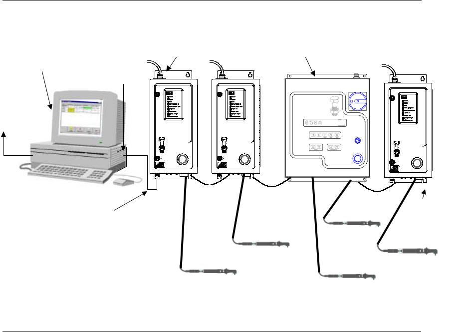
This is a permanent mode of operation in which the computer and controllers are connected via the same network hub. See Figure 1-1.
This type of network requires:
•Pentium Class computer (500 MHz or above).
•Microsoft Windows 95, 98, 2000, or Windows NT, version 4.0 or above with TCP/IP communications protocol installed.
•At least 64 MB RAM for Windows 95, 98 or 2000, or 128 MB RAM for Windows NT.
•Installed Ethernet Interface Card in the controller and the computer.
•Visual Supervisor installed in permanent mode.
•Shielded 10Base-T cable and Ethernet connector.
In this configuration, the host computer running Visual Supervisor provides data collection, diagnostics and configuration functions for all the controllers, but the hub is the connection point for the LAN. See Figure 1-1 for details. To set up an Ethernet network, refer to Chapter 5. Setting Up the Ethernet.
Page 1-2 |
T-38324-A |
39-30-38324 |

Example of a “Permanent” (Embedded) Ethernet Network (Using Mini Controllers with Ethernet)
Pentium Class Computer running Windows 95, 98, 2000 |
|
CS4000 Mini Controllers with Ethernet |
|
|
||||||
or Windows NT, version 4.0 or above. It also has an |
|
|
|
|||||||
|
|
|
|
|
|
|
|
|
||
installed Ethernet interface card. Each controller has an |
|
|
|
|
|
|
|
|
|
|
Ethernet connector. |
Ethernet Card |
|
|
|
|
|
|
|
|
|
Visual Supervisor is |
|
|
|
|
|
|
|
|
|
|
|
|
|
|
|
|
|
|
|
|
|
running on the |
|
|
|
|
|
|
|
|
|
|
computer, plus an |
|
|
|
|
|
|
|
|
|
|
optional Application |
|
|
|
|
|
|
|
|
|
|
Program Interface |
|
|
|
|
|
|
|
|
|
|
(API) for data |
|
|
|
|
|
|
|
|
|
|
collection. |
|
CS4000 mini |
|
CS4000 mini |
|
CS4000 mini |
|
|||
|
SYSTEM |
|
SYSTEM |
|
SYSTEM |
|
||||
|
|
CONTROLLER |
|
CONTROLLER |
|
CONTROLLER |
|
|||
|
|
|
tool |
|
tool |
|
tool |
|||
|
|
-motive4 5 6 |
|
-motive4 5 6 |
|
-motive4 5 6 |
|
|||
|
|
tech |
3 |
7 |
tech |
3 |
7 |
tech |
3 |
7 |
|
|
2 |
8 |
2 |
8 |
2 |
8 |
|||
LAN |
|
|
|
|
||||||
|
|
1 |
* |
|
1 |
* |
|
1 |
* |
|
|
|
|
|
|
|
|
||||
|
|
|
|
|
|
|
|
|
|
|
Chapter 1. Overview
CS4000 mini
SYSTEM
CONTROLLER
|
|
tool |
-motive4 5 6 |
||
tech |
3 |
7 |
|
2 |
8 |
|
1 |
* |
Network
Hub
NOTE: Each controller is attached to the hub, which is in turn attached to the host computer. Visual Supervisor provides data collection, diagnostics and configuration functions, but the individual controllers may also have changes made to them. These changes are then communicated back to the computer, via the Ethernet, and the change recorded in Visual Supervisor.
Figure 1-1. Example of an Ethernet Network with a Connected Portable Laptop
A laptop running Visual Supervisor is attached, via an RS-232 compatible port, and used to make setup changes for an individual controller on or off the network.
May 2002 |
T-38324-A PRELIMINARY DRAFT |
Page 1-3 |

CS4000 Mini Controller with Ethernet
Using a 485 Network using SDLC
In a 485 network, the controller is linked to a LAN, via cable between the first controller’s RS-485 connector and the port for the Synchronous Data Link Control (SDLC) card installed on the host computer. Each controller in the 485 network is connected to the next in a daisy chain fashion. The computer is connected to the first controller, the first controller is connected to the second controller, and so on until the network terminates with the last controller. See Figure 1-2. In this mode of operation, you can have as many as 32 TCMs attached and running from a single supervising computer.
This type of network requires:
•Pentium class computer (500 MHz or above).
•Microsoft Windows NT, version 4.0 or above.
•At least 128 MB RAM.
•Installed SDLC card.
•Visual Supervisor installed on the computer in permanent mode.
•RS-485 cable and connector.
In this configuration, the computer permanently connected to the network runs Visual Supervisor which now takes on the role of supervising all of the controllers on the LAN for both data and parameter set information, as well as being the connection point for the LAN. To set up a 485 network, refer to Chapter 6. Setting Up the 485 Network.
Page 1-4 |
T-38324-A |
39-30-38324 |
Example of a “Permanent” (Embedded) 485 Network (Using CS4000 KDM and Mini Controllers with SDLC)
CS4000 Mini Controller each contains Pentium Class Computer running one Tool Control Module (TCM) Windows NT, version 4.0 or above, with an
SDLC card and RS-485 port on each controller.
LAN
CS4000 mini
SYSTEM
CONTROLLER
|
|
tool |
-motive4 5 6 |
||
tech |
3 |
7 |
|
2 |
8 |
|
1 |
* |
CS4000 mini
SYSTEM
CONTROLLER
|
|
tool |
-motive4 5 6 |
||
tech |
3 |
7 |
|
2 |
8 |
|
1 |
* |
Chapter 1. Overview
KDM based CS4000 Compact Controller (in read-only mode) contains one or two TCMs
CS4000 mini
SYSTEM
CONTROLLER
|
|
tool |
-motive4 5 6 |
||
tech |
3 |
7 |
|
2 |
8 |
|
1 |
* |
TCM termination point
NOTE:
Figure 1-2. Example of a 485 Network
May 2002 |
T-38324-A PRELIMINARY DRAFT |
Page 1-5 |
CS4000 Mini Controller with Ethernet
Using the RS-232 Serial Port
In this configuration, a laptop PC loaded with the Visual Supervisor software is linked to the controller’s RS-232 serial port. See Figure 1-1 on page 1-3. Because the laptop can be disconnected from one Mini Controller and reconnected to another, VS is said to be operating in portable mode. The controller in this scenario may not be part of a network typically so that it, the cable and nutrunner comprise a stand-alone fastening system.
This type of operation requires:
•Pentium class laptop computer.
•Microsoft Windows 95, 98, 2000, or Windows NT version 3.0 or above.
•At least 64 MB RAM for Windows 95, 98 or 2000, or 128 MB RAM for Windows NT.
•Visual Supervisor installed on the laptop in portable mode.
•RS-232 cable and connector.
If the laptop PC is connected to a controller that is also connected to a network, the host computer adopts any changes made by the laptop PC to the controller. While the laptop computer is making changes, the host cannot make setup changes to the same controller. The Visual Supervisor program being run by the host computer grays out every field for that particular controller. When the laptop PC is no longer connected to the controller, the host computer can once again make changes.
NOTE: To attach and use a laptop to view, edit or collect data from a controller on a network, you must have Visual Supervisor version 3.20 or higher installed on the host and laptop computers, and DCM 4.06 or higher installed on the controllers.
Using an Interbus-S Digital I/O Module
The optional Interbus-S module can be added to the controller, to provide eight soft-programmable digital inputs and eight soft-programmable digital outputs. You can assign the function of these inputs and outputs using the Visual Supervisor program. Refer to the Visual Supervisor User’s Guide (part number 39-40-34823) for details.
You can use the Interbus-S module to connect the controller to a Programmable Logic Controller (PLC). When the PLC reads a barcode successfully, for example, it sends a signal as an Interbus-S module input into the controller that tells the controller to allow the operator to perform a rundown. The controller then sends a signal to the PLC as an Interbus-S module output that indicates when a good rundown or a bad rundown has been performed.
Page 1-6 |
T-38324-A |
39-30-38324 |

Chapter 1. Overview
Using the Siemens 3964R Barcode Protocol
The RS-422 port on the controller supports the Siemens 3964R barcode protocol. This protocol provides an error checked point-to-point method of sending barcode data to the controller. If the controller receives a corrupt or incomplete barcode, the scanner sends the barcode information again.
For example, you might choose to attach a barcode scanner and controllers to the same RS-422 network. A barcode is read by the scanner, which then sends the barcode to every controller attached to the network. This means you do not have to scan the barcode at each individual controller.
NOTE: If, for any reason, the scanner does not send a barcode using the RS-422 port, then the Printer/Barcode port on each controller provides you with a backup. You can always scan the barcode at an individual controller using a scanner attached to the Printer/Barcode serial port until the scanner attached to the RS-422 port starts sending barcode data again.
For further details about the Siemens 3964R Barcode Protocol, refer to the Protocol Definition of the 3964/3964R Procedures available from Siemens (Siemens Part Number C79000-B8576-C191-01).
Deciding How to Set Up the Controller
It is more than likely that you will not need to use all methods of connecting the controller to a network and/or external devices. If you decide to use the 485 network link then you will not need the Ethernet link, nor vice versa, as they perform the same function. You may or may not want the controller to communicate with a PLC and/or an external barcode scanner, in which case, you do not need an Interbus-S I/O module or a link via the RS-422 port.
The following chapter describes the basic components of the controller so you can familiarize yourself with them before you install it. Chapter 4. Installing the CS4000 Mini Controller with Ethernet describes how to mount the controller and how to make sure you fulfill its power requirements.
Chapter 5. Setting Up the Ethernet, Chapter 6. Setting Up the 485 Network and Chapter 7. Setting Up the RS-232 Link describe how to install the various components that have been discussed in this chapter.
May 2002 |
T-38324-A |
Page 1-7 |

CS4000 Mini Controller with Ethernet
(This page is left blank intentionally.)
Page 1-8 |
T-38324-A |
39-30-38324 |

2. Think Safety First!
Working with fastening tools can be dangerous if safe and proper procedures are not followed. As with all machinery, certain hazards can be involved with the operation of the product. Using these tools with respect and caution will considerably lessen the possibility of personal injury, however, if normal safety precautions are overlooked or ignored personal injury to the operator may result.
Always use common sense and exercise caution when using these tools. They can produce high torque that, unless properly compensated for, could cause personal injury. Remember, your personal safety is your responsibility.
Only GSE tech-motive tool-qualified service technicians should perform the procedures covered in this manual. If you are an operator or service technician, you should become familiar with the contents of this manual before operating, servicing, or maintaining any part of the CS4000 Mini Controller with Ethernet, including the 66 Series fastening tools. Familiarization with all components of the system can minimize the possibility that an accident or injury might occur.
GSE tech-motive tool assumes no responsibility for personal injury or damage to equipment resulting from misuse of these tools. After reviewing this manual you should also review all safety procedures provided by your company and the equipment installer.
WARNING! Failure to follow these steps may result in serious personal injury.
May 2002 |
T-38324-A |
Page 2-1 |

CS4000 Mini Controller with Ethernet
General Machine Safety
•FOR YOUR OWN SAFETY READ THE INSTRUCTION MANUAL THOROUGHLY PRIOR TO OPERATING THE TOOL.
•DO NOT WORK IN A DANGEROUS ENVIRONMENT. Do not use power tools in a damp or wet location or expose them to rain, oils, or corrosive fluids.
•KNOW THE LOCATION OF POWER DISCONNECTS AND EMERGENCY STOP BUTTONS PRIOR TO OPERATING THIS EQUIPMENT.
•KEEP ALL ELECTRICAL PANELS CLOSED DURING OPERATION. High voltage present inside enclosure panels can result in personal injury. Do NOT bypass or defeat electrical safety devices. Turn the power actuator to the OFF position prior to any servicing or maintenance of the controller.
•OBSERVE ALL GOVERNMENT AND/OR COMPANY POWER LOCKOUT STANDARDS.
•NEVER OPERATE SOLENOID VALVES, LIMIT SWITCHES OR RELAYS MANUALLY as this practice can create dangerous, unexpected machine movements.
•SECURE THE TOOL. Tools that develop torque can produce hazardous torque reactions. Always be sure that the tool is properly fixtured to absorb reaction as a fastener is tightened. Never operate a tool capable of high torque without proper fixturing.
•SECURE WORK. Avoid situations where the part being fastened breaks loose and can cause damage.
•NEVER TOUCH OR ATTEMPT TO STOP MOVING MACHINERY OR PARTS WITH YOUR HANDS, OTHER PARTS OF YOUR BODY, OR MAKESHIFT DEVICES.
•DO NOT OPERATE THE TOOL WHILE UNDER THE INFLUENCE OF ALCOHOL, DRUGS OR MEDICATION THAT CAN IMPAIR YOUR JUDGMENT.
•REPORT ALL UNSAFE WORKING CONDITIONS OR PRACTICES TO YOUR SUPERVISOR AND / OR SAFETY DEPARTMENT FOR CORRECTION.
•WEAR APPROVED SAFETY GLASSES AT ALL TIMES.
•DO NOT WEAR JEWELRY, especially bracelets and rings, while operating the fastening tools. Keep hands and fingers away from all rotating parts and avoid situations where clothing can become tangled in the tool. Secure loose fitting clothing, neckties, and long hair. Wear medical alert identification cautiously.
•DO NOT OVERREACH. Keep proper footing and balance at all times.
•KEEP YOUR WORK AREA CLEAN. Do not work on or near slippery floors or surfaces. Avoid situations where the tool reacts against unexpected obstacles. Do not operate electrical equipment while standing on a wet floor.
Page 2-2 |
T-38324-A |
39-30-38324 |

Chapter 2. Think Safety First!
•MAINTAIN TOOLS IN TOP CONDITION. Keep tools properly lubricated and clean. If any wires become frayed or exposed, replace them immediately. Prevent dirt, grease or contaminants from getting into the tool.
•REDUCE THE RISK OF UNINTENTIONAL STARTING. Be careful how the tool is left unattended. Avoid resting it on its throttle lever to prevent false starts.
•CONTROL THE DIRECTION OF ROTATION. The reaction torque changes direction when going from forward to reverse. Always be aware in which direction the tool will rotate prior to using it. If the tool is not fixtured this will allow you to brace for the proper direction of torque reaction.
•CHECK DAMAGED PARTS. Before further use of a tool, any part of the tool that is damaged should be carefully checked to ensure that it will operate properly and perform its intended function. Check for alignment of moving parts, breakage of parts, mounting, and any other conditions that may affect its operation. Never operate a tool that has damaged or exposed wires. Never operate a tool that has any part of the powertrain, other than the output spindle, exposed.
Electrical Safety
Only qualified and properly trained personnel should perform electrical/electronic troubleshooting and repair. Consider the following electrical system safety guidelines:
•Before you troubleshoot or service a fastening system station, be sure you have an up- to-date and appropriate set of electrical drawings for that station.
•Remove metal items, such as rings, metal necklaces, wristwatches and jewelry, as these can create electrical hazards. Wear medical alert identification cautiously.
•Wear safety glasses, but avoid wearing those that have metal rims or metal side shields.
•It may be necessary to troubleshoot equipment while the power is ON. ONLY qualified, trained personnel should do this. During these instances, open only the panels, doors, or covers which need to be opened. Know the voltage present at all points before you begin troubleshooting.
•Use properly insulated tools when working on electrical equipment to reduce the possibility of shock. Make sure the insulation is adequate to safeguard against the high voltages present.
•If you must work on the electrical system, be sure the main disconnect switch on the power panel is in the OFF position and locked out with locks from each trade involved in the repair.
•Do not attempt to modify or repair the machine without the approval of the proper authorities.
•Use approved fuse pullers when changing fuses.
•Never use jumper wires or fuse substitutes to replace specified fuses.
May 2002 |
T-38324-A |
Page 2-3 |

CS4000 Mini Controller with Ethernet
•Always use fuses of a capacity smaller than or equal to the safe capacity of the line or the equipment it serves.
•Before you work on any circuit, check it with an appropriate testing device to be sure voltage is not present.
•Install temporary wiring as safely as possible and replace it with permanent wiring as soon as possible. Install grounding wherever it is needed in the final installation. If modifications are made to the system wiring, drawings must be revised to illustrate this change.
•Know how to deal with electrical fires properly. Keep carbon dioxide and powder extinguishers handy.
Page 2-4 |
T-38324-A |
39-30-38324 |

3. Identifying the Components
The CS4000 Mini Controller with Ethernet houses all the standard functions of the standard CS4000 Mini Controller, but also has the ability to communicate across an Ethernet Local Area Network (LAN) using the standard Ethernet protocol, Transmission Control Protocol/Internet Protocol (TCP/IP).
This chapter is designed to familiarize you with the components of the CS4000 Mini Controller with Ethernet. It has three sections to help you locate all the major components easily:
•Front Panel
•Top and Bottom Panel
•Enclosure Interior
Each section includes figures that call out the components. Descriptions of the components follow the figures.
May 2002 |
T-38324-A |
Page 3-1 |
CS4000 Mini Controller with Ethernet
Front Panel
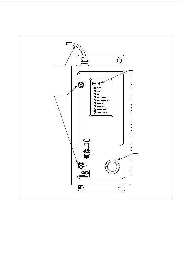
Figure 3-1 shows the front panel components of the CS4000 Mini Controller with Ethernet.
AC Power
Cord LED
Display
Access Screws
CS4000 mini
SYSTEM
CONTROLLER
|
tool |
|
-motive4 5 |
6 |
|
tech |
3 |
7 |
|
2 |
8 |
|
1 |
* |
Parameter
Select Switch
Figure 3-1. Front Panel View
NOTE: The AC power cord is described in the Top and Bottom Panel section later in this chapter.
LED Display
The LED display shows you the torque, or torque and angle value for the most recent rundown. It also scrolls messages for the operator. For example, if a barcode scan is required before the next rundown, the operator sees a barcode prompt on the LED display.
Page 3-2 |
T-38324-A |
39-30-38324 |
Chapter 3. Identifying the Components
Parameter Set Switch
Turn the dial to select the parameter set you wish to use for the next rundown. Select parameter sets using the parameter set switch or Visual Supervisor.
Access Screws
The access screws keep the front panel of the controller fastened. To un-fasten them you need a No.2 cross-tip (Phillips) head screwdriver.
Top and Bottom Panel
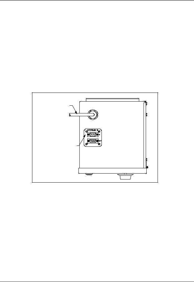
Figure 3-2 shows the top panel components of the CS4000 Mini Controller with Ethernet.
AC Power Cord |
Interbus-S I/O Connector |
(Optional) |
Figure 3-2. Top Panel View
AC Power Cord
A power cord connection is available on the top of CS4000 Mini Controller with Ethernet. The power cords it accepts are the 6-ft American style 20A, 240V AC power cord (part number 299250-32835) or the 2.5-m European style 10A, 240V power cord (part number 22-30-1021).
Interbus-S I/O Connector
A nine-position, serial Interbus-S connector may be mounted optionally on the top of the CS4000 Mini Controller with Ethernet. This enables the controller to exchange up to eight digital inputs and outputs with an external Programmable Logic Controller (PLC). If an Interbus-S module is not included in the controller, the Interbus-S I/O connector is covered. To find out details about the Interbus-S module, refer to the Interbus-S Module section later in this chapter.
May 2002 |
T-38324-A |
Page 3-3 |
Loading...