


/ Cofimco Fan – Adjustable Hub /
User Manual 03-11A

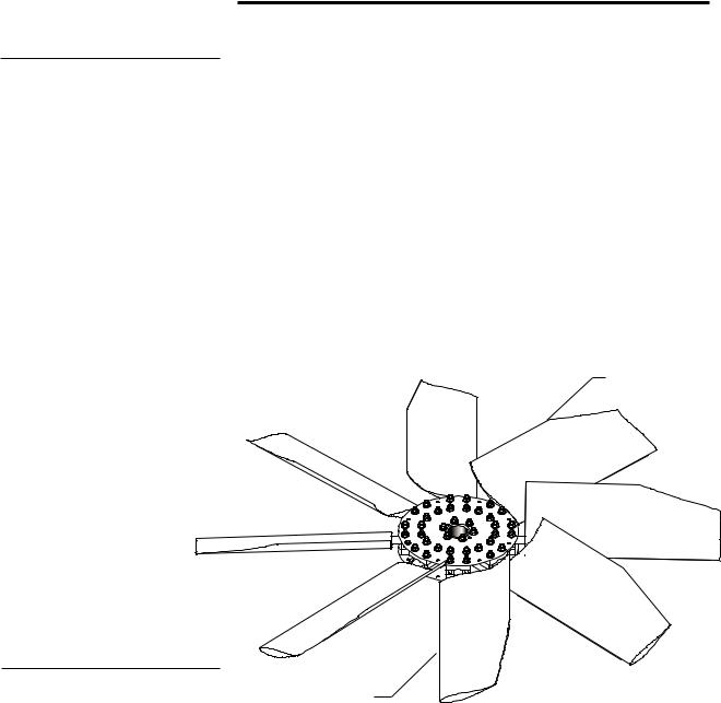
Fan Components
102
101
V11
102
104
VBA
Figure 1—Typical Fan Assembly
X14
W29
101
103
104
X12
200
103
W29
Order No.________________________________________
Trial Pitch Angle__________________________________
Final Pitch Angle_________________________________
Speed-rpm_ _____________________________________
Contract hp______________________________________
2
Note
Figure 2
Fan Assembly Instructions
The following instructions apply to installations having straight bores or tapered output shafts without split taper bushings.
It is convenient to preassemble the fan prior to installation on the driving shaft.
1—Select a large open area corresponding to the fan diameter.
2—Position the fan hub in the center of the work area with the center spool 101 oriented as shown in Figure 1.
3—Secure blade retention sleeves 104 to the blade 200 using machine bolt V11 and locking nut X12. Tighten 3⁄8" nut X12 to 40 ft·lbƒ.
4—Position the blade clamp blocks 103 around the blade shank so
that the blade 200 droops slightly downward when the blade clamp |
|
hardware is tight. |
TRAILING |
|
|
|
EDGE |
LEADING EDGE
5—Position the blade clamps and blade between the hub plates 102 to align bolt holes. Loosely install 5⁄8" bolts VBA, flat washers W29 and self locking nuts X14 to secure blades. Finger tighten all 5⁄8" nuts.
6—On fans where the blades overlap at the hub be sure to have the leading edge under the trailing edge of the forward blade. Refer to Figure 2.
7—Pull the blades radially outward until the blade retention sleeve
bears against the back side of the blade clamp. |
|
|
3
 Loading...