

Page 1
Instruction Manual
CombiPro
Heavy duty process pump
according to API 610
Orginal instructions
Read and understand this manual prior to
operating or servicing this product.
CR/EN (1004) 4.0
Page 2
EC Declaration of conformity
(Directive 2006/42/EC, appendix II-A)
Manufacturer
SPX Process Equipment NL B.V.
Dr. A.F. Philipsweg 51
9403 AD Assen
The Netherlands
hereby declares that all pumps member of productfamilies
CombiChem, CombiDirt, CombiFlex(U)(B), CombiPrime H, CombiLine, CombiLineBloc,
CombiMag, CombiMagBloc, CombiNorm, CombiPro(M)(V), CombiPrime V, CombiSump,
CombiWell, FRE, FRES, FREF, FREM, KGE(L), KGEF, HCR, MCH(W)(S), MCHZ(W)(S),
MCV)(S), PHA, MDR whether delivered without drive (last position of serial number = B),
or delivered as an assembly with drive (last position of serial number = A), are in
conformity with the provisions of Directive 2006/42/EC (as altered most recently) and
where applicable the following directives and standards:
• EC directive 2006/95/EG, "Electric equipment for use within certain voltage limits"
• standards EN-ISO 12100 part 1 & 2, EN 809
The pumps to which this declaration refers may only be put into operation after they have
been installed in the way prescribed by the manufacturer, and, as the case may be, after
the complete system of which these pumps form part, has been made to fulfil the
requirements of Directive 2006/42/EC (as altered most recently).
CombiBloc, CombiBlocHorti,
Declaration of incorporation
(Directive 2006/42/EC, appendix II-B)
Manufacturer
SPX Process Equipment NL B.V.
Dr. A.F. Philipsweg 51
9403 AD Assen
The Netherlands
hereby declares that the partly completed pump (Back-Pull-Out unit), member of
productfamilies
CombiPrime H, CombiLine, CombiLineBloc, CombiMag, CombiMagBloc, CombiNorm,
CombiPro(M)(V), CombiPrime V, FRE, FRES, FREF, FREM, KGE(L), KGEF, HCR, PHA, MDR
in conformity with the following standards:
• EN-ISO 12100 parts 1 & 2, EN 809
and that this partly completed pump is meant to be incorporated into the specified pump
unit and may only be put into use after the complete machine of which the pump under
consideration forms part has been made and declared to comply with that directive.
Assen, January 1st 2010
CombiBloc, CombiBlocHorti, CombiChem, CombiDirt, CombiFlex(U)(B),
is
G.A. Schaafsma,
General Manager
EC/EN (1001) 5.1 1
Page 3

2 EC/EN (1001) 5.1
Page 4

CombiPro
Instruction manual
CombiPro
All technical and technological information in this manual as well as possible drawings
made available by us remain our property and shall not be used (otherwise than for the
operation of this pump), copied, duplicated, made available to or brought to the notice of
third parties without our prior written consent.
SPX Process Equipment NL B.V. (hereafter called Johnson Pump) is part of SPX
Process Equipment AB. The core activities of SPX Process Equipment AB are the
development, production, sale and maintenance of pumps and pump units.
SPX Process Equipment NL B.V.
P.O. Box 9
9400 AA Assen
The Netherlands
Tel. +31 (0)592 376767
Fax. +31 (0)592 376760
www.johnson-pump.com or www.spxft.com
© 2008 SPX Process Equipment NL B.V.
CR/EN (1004) 4.0 3
Page 5
4 CR/EN (1004) 4.0
Page 6

CombiPro
Table of Contents
1 Introduction 9
1.1 Preface 9
1.2 Safety 9
1.3 Guarantee 10
1.4 Inspection of delivered items 10
1.5 Instructions for transport and storage 10
1.5.1 Weight 10
1.5.2 Use of pallets 10
1.5.3 Hoisting 11
1.5.4 Storage 11
1.6 Ordering parts 12
2 General 13
2.1 Pump description 13
2.2 Applications 13
2.3 Type code 14
2.4 Serial number 15
2.5 Construction 15
2.6 Pump casing 15
2.7 Impeller 16
2.8 Pump cover 16
2.9 Wear rings 16
2.10 Mechanical seal 16
2.11 Bearing 16
2.12 Base plate and coupling 16
2.13 Application area 17
2.14 Re-use 17
2.15 Scrapping 17
3Installation 19
3.1 Safety 19
3.2 Preservation 19
3.3 Environment 19
3.4 Mounting 20
3.4.1 Installation of a pump unit 20
3.4.2 Assembling a pump unit 20
3.4.3 Alignment of the coupling 20
3.4.4 Tolerances for aligning the coupling 21
3.4.5 Grouting base plate 21
3.5 Piping 22
CR/EN (1004) 4.0 5
Page 7

3.6 Accessories 23
3.7 Connection of the electric motor 23
4 Commissioning 25
4.1 Inspection of the pump 25
4.2 Inspection of the motor 25
4.3 Pumps with oil-bath lubricated bearings 25
4.4 Preparing the pump unit for commissioning 26
4.5 Checking the sense of rotation 26
4.6 Start-up 26
4.7 Pump in operation 26
4.8 Noise 26
5 Maintenance 27
5.1 Daily maintenance 27
5.2 Mechanical seal 27
5.3 Lubrication of the bearings 27
5.4 Environmental influences 28
5.5 Noise 28
5.6 Faults 28
6 Problem solving 29
7 Disassembly and assembly 31
7.1 Precautionary measures 31
7.2 Special tools 31
7.3 Draining 31
7.3.1 Liquid draining 31
7.3.2 Oil draining 31
7.4 Back-Pull-Out system 32
7.4.1 Disassembling the guard 32
7.4.2 Disassembling the Back-Pull-Out unit 32
7.4.3 Assembling the Back-Pull-Out unit 32
7.4.4 Assembling the guard 33
7.5 Replacing the impeller and the wear ring 33
7.5.1 Disassembling the impeller 33
7.5.2 Mounting the impeller 33
7.5.3 Disassembling the wear rings 34
7.5.4 Assembling the wear rings 35
7.6 Mechanical seal 36
7.6.1 Instructions for mounting a cartridge seal 36
7.6.2 Disassembling a cartridge seal 36
7.6.3 Mounting a cartridge seal 36
7.7 Bearing 37
7.7.1 Instructions for assembly and disassembly of bearings 37
7.7.2 Disassembling bearing 37
7.7.3 Assembling bearing 38
8Dimensions 39
8.1 Pump dimensions 39
8.2 Flange dimensions 40
8.2.1 Flange dimensions ASME B16.5 150lbs (ISO7005 PN20) 40
8.2.2 Flange dimensions ASME B16.5 300lbs (ISO7005 PN50) 40
8.3 Pump dimensions 41
8.4 Pump-motor unit 41
6 CR/EN (1004) 4.0
Page 8

CombiPro
9Parts 43
9.1 Ordering parts 43
9.1.1 Order form 43
9.1.2 Recommended spare parts 43
9.2 Pump 44
9.2.1 Sectional drawing pump 44
9.2.2 Parts list pump 45
9.3 Mechanical seal piping plan 11 - tubing 47
9.3.1 Drawing plan 11 - tubing 47
9.3.2 Parts list plan 11 - tubing 47
9.4 Mechanical seal piping plan 11 - flanged 48
9.4.1 Drawing plan 11 - flanged 48
9.4.2 Parts list plan 11 - flanged 48
9.5 Oil chamber jacket 49
9.5.1 Drawing oil chamber jacket 49
9.5.2 Parts list oil chamber jacket 49
9.6 Pump casing jacket 50
9.6.1 Drawing pump casing jacket 50
9.6.2 Parts list pump casing jacket 50
10 Technical data 51
10.1 Tightening moments 51
10.1.1 Tightening moments for bolts and nuts 51
10.1.2 Tightening moments for cap nut 51
10.1.3 Torques settings for nuts for pump casing 52
10.2 Permissible forces and moments on the flanges 53
10.2.1 Allowable forces and moments on suction and discharge flanges 54
10.2.2 Allowable forces and moments on the drain flange 55
10.3 Lubricants 55
10.3.1 Oil 55
10.3.2 Oil contents 55
10.4 Hydraulic performance 56
10.4.1 Performance overview cast steel material class S-1 56
10.4.2 Performance overview material classes S-6, S-8, C-6, A-8 58
10.5 Noise data 60
10.5.1 Pump noise as a function of pump power 60
10.5.2 Noise level of entire pump unit 61
Index 63
Order form for spare parts 65
CR/EN (1004) 4.0 7
Page 9

8 CR/EN (1004) 4.0
Page 10
CombiPro
1 Introduction
1.1 Preface
This manual is intended for technicians and maintenance staff and for those who are in
charge of ordering spare parts.
This manual contains important and useful information for the proper operation and
maintenance of this pump. It also contains important instructions to prevent potential
accidents and damage, and to ensure safe and fault-free operation of this pump.
! Read this manual carefully before commissioning the pump, familiarize
yourself with the operation of the pump and strictly obey the instructions!
The data published here comply with the most recent information at the time of going to
press. However they may be subject to later modifications.
Johnson Pump reserves the right to change the construction and design of the products
at any time without being obliged to change earlier deliveries accordingly.
1.2 Safety
This manual contains instructions for working safely with the pump. Operators and
maintenance staff must be familiar with these instructions.
Below is a list of the symbols used for those instructions and their meaning:
Personal danger for the user. Strict and prompt observance of the
corresponding instruction is imperative!
! Risk of damage or poor operation of the pump. Follow the corresponding
instruction to avoid this risk.
➢ Useful instruction or tip for the user.
Items which require extra attention are shown in bold print.
This manual has been compiled by Johnson Pump with the utmost care. Nevertheless
Johnson Pump cannot guarantee the completeness of this information and therefore
assumes no liability for possible deficiencies in this manual. The buyer/user shall at all
times be responsible for testing the information and for taking any additional and/or
deviating safety measures. Johnson Pump reserves the right to change safety
instructions.
CR/EN (1004) 4.0 Introduction 9
Page 11

1.3 Guarantee
Johnson Pump shall not be bound to any guarantee other than the guarantee accepted
by Johnson Pump. In particular, Johnson Pump will not assume any liability for explicit
and/or implicit guarantees such as but not limited to the marketability and/or suitability of
the products supplied.
The guarantee will be cancelled immediately and legally if:
• Service and/or maintenance is not undertaken in strict accordance with the
instructions.
• The pump is not installed and operated in accordance with the instructions.
• Necessary repairs are not undertaken by our personnel or are undertaken without our
prior written permission.
• Modifications are made to the products supplied without our prior written permission.
• The spare parts used are not original Johnson Pump parts.
• Additives or lubricants used are other than those prescribed.
• The products supplied are not used in accordance with their nature and/or purpose.
• The products supplied have been used amateurishly, carelessly, improperly and/or
negligently.
• The products supplied become defective due to external circumstances beyond our
control.
All parts which are liable to wear are excluded from guarantee. Furthermore, all
deliveries are subject to our “General conditions of delivery and payment”, which will be
forwarded to you free of charge on request.
1.4 Inspection of delivered items
Check the consignment immediately on arrival for damage and conformity with the advice
note. In case of damage and/or missing parts, have a report drawn up by the carrier at
once.
1.5 Instructions for transport and storage
1.5.1 Weight
A pump or a pump unit is generally too heavy to be moved by hand. Therefore, use the
correct transport and lifting equipment. Weight of the pump or pump unit are shown on
the label on the cover of this manual.
1.5.2 Use of pallets
Usually a pump or pump unit is shipped on a pallet. Leave it on the pallet as long as
possible to avoid damages and to facilitate possible internal transport.
! When using a forklift always set the forks as far apart as possible and lift the
package with both forks to prevent it from toppling over! Avoid jolting the
pump when moving it!
10 Introduction CR/EN (1004) 4.0
Page 12
CombiPro
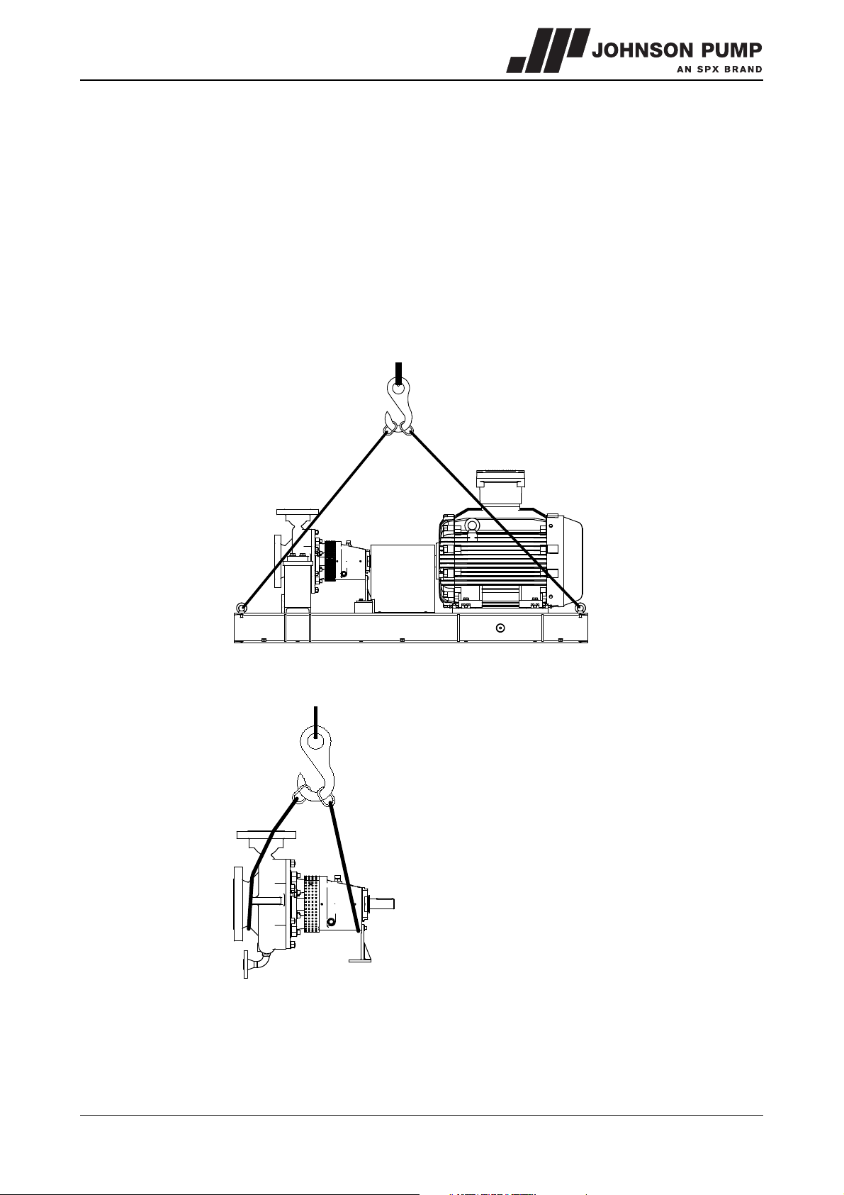
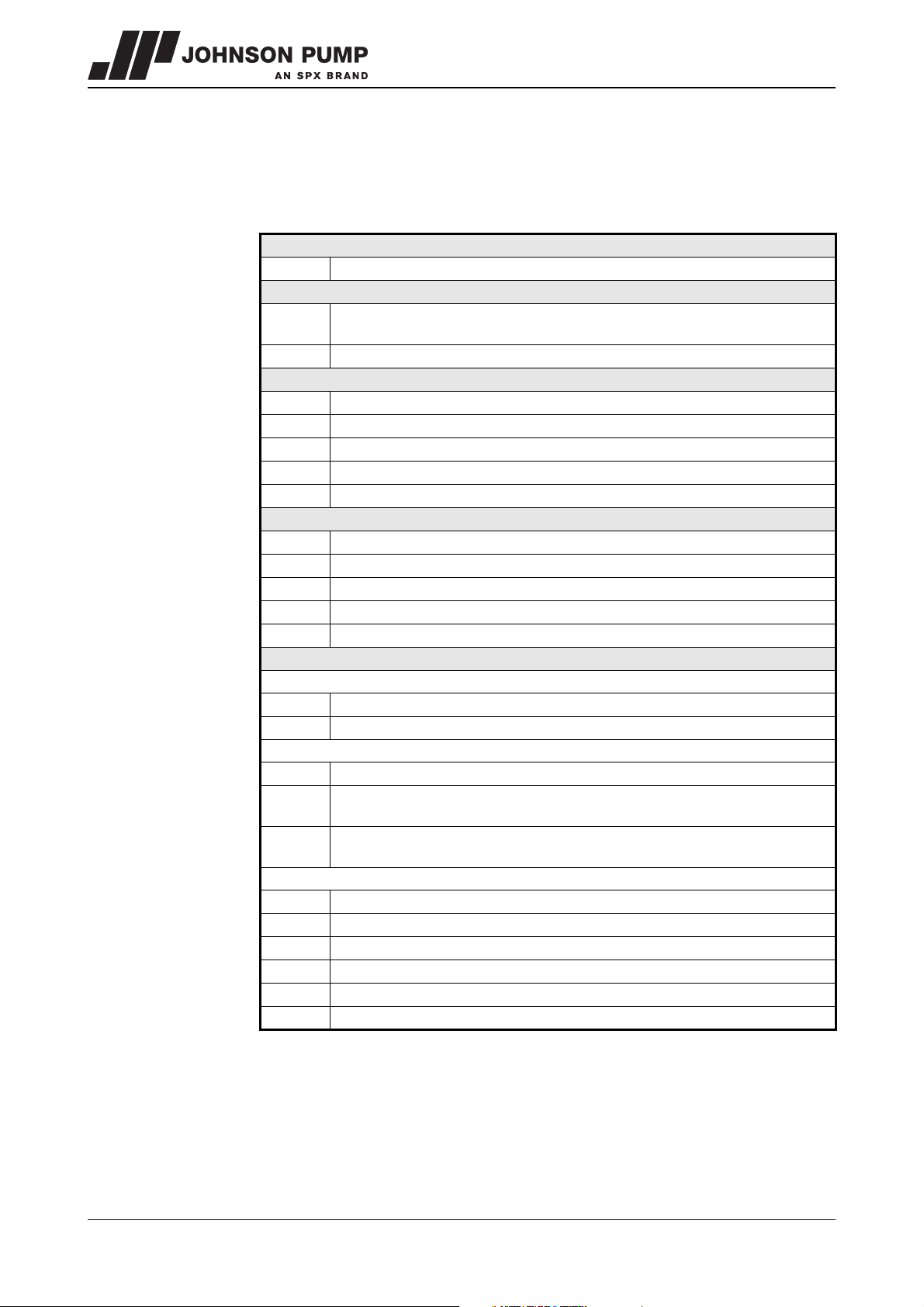
1.5.3 Hoisting
When hoisting a pump or complete pump units the straps must be fixed in accordance
with figure 1 and figure 2.
When lifting a pump or a complete pump unit always use a proper and sound
lifting device, approved to bear the total weight of the load! Never go
underneath a load that is being lifted!
! If the electric motor is provided with a lifting eye, this lifting eye is intended
only for the purpose of carrying out service activities to the electric motor!
The lifting eye is designed to bear the weight of the electric motor only!
It is NOT permitted to lift a complete pump unit at the lifting eye of an electric
motor!
Figure 1: Lifting instructions for pump unit.
Figure 2: Lifting instructions for single pump.
1.5.4 Storage
If the pump is not to be used immediately the pump shaft must be turned by hand twice
per week.
CR/EN (1004) 4.0 Introduction 11
Page 13

1.6 Ordering parts
This manual contains a survey of the spare parts recommended by Johnson Pump as well
as the instructions for ordering them. A fax-order form is included in this manual.
You should always state all data stamped on the type plate when ordering parts and in
any other correspondence regarding the pump.
➢ This data is also printed on the label on the front of this manual.
If you have any questions or require further information with regard to specific subjects,
then do not hesitate to contact Johnson Pump.
12 Introduction CR/EN (1004) 4.0
Page 14

CombiPro
2 General
2.1 Pump description
The CombiPro represents a range of horizontal "heavy duty" centrifugal pumps. The
design of this range of pumps is based on the guidelines for: "Centrifugal Pumps for
Petroleum, Petrochemical and Natural Gas Industries" from the "American Petroleum
Institute" otherwise known as the API Standard 610 (identical to ISO 13709). The
CombiPro range therefore meets the high requirements which have been set by the
refineries and the petrochemical industry.
The API 610 contains important technical guidelines in order to guarantee optimum
reliability. The CombiPro amply complies with these requirements. This has been
demonstrated through extensive research and can be supported on the basis of
advanced methods of calculation.
2.2 Applications
• In general, this pump can be used for thin, clean or slightly polluted liquids. These
liquids should not affect the pump materials.
• The maximum allowed system pressure and temperature and the maximum speed
depend on the pump type and the pump construction.
• Further details about the application possibilities of your specific pump are mentioned
in the order confirmation and/or in the data sheet enclosed with the delivery.
• Do not use the pump for purposes other than those for which it is delivered without
prior consultation with your supplier.
Using a pump in a system or under system conditions (liquid, working
pressure, temperature, etc.) for which it has not been designed may hazard
the user!
CR/EN (1004) 4.0 General 13
Page 15
2.3 Type code
Pumps are available in various designs. The main characteristics of the pump are shown
in the type code.
Example: CR 50A-200 A-8 1CW-FX
CR
50A
200
S-1
S-6
S-8
C-6
A-8
S-1
S-6
S-8
C-6
A-8
Arrangement 1
1CW-FX
1CW-FL
Arrangement 2
2CW-CW
2CW-CS
2NC-CS
Arrangement 3
3CW-FB
3CW-BB
3CW-FF
3NC-BB
3NC-FF
3NC-FB
Pump family
CombiPro
Pump size
discharge connection [mm]. A and B design pump types have the same
designation though they have different hydraulic performances
nominal impeller diameter [mm]
Pump casing material according to API 610
carbon steel
carbon steel
carbon steel
12% CHR
316 AUS
Impeller material according to API 610
cast iron
12% CHR
316 AUS
12% CHR
316 AUS
Shaft sealing code according to API 682
Contacting single wet seal with a fixed throttle bushing
Contacting single wet seal with a floating throttle bushing
Liquid buffer fluid, Dual contacting wet seals
Gas buffer fluid or no buffer fluid, Contacting wet inner seal with a
containment seal
Gas buffer fluid or no buffer fluid, Non-contacting inner seal with a
containment seal
Liquid barrier fluid, Contacting wet seals in a face-to-back configuration
Liquid barrier fluid, Contacting wet seals in a back-to-back configuration
Liquid barrier fluid, Contacting wet seals in a face-to-face configuration
Gas barrier fluid, Non-contacting seals in a back-to-back configuration
Gas barrier fluid, Non-contacting seals in a face-to-face configuration
Gas barrier fluid, Non-contacting seals in a face-to-back configuration
14 General CR/EN (1004) 4.0
Page 16
CombiPro
2.4 Serial number
Serial number of the pump or pump unit are shown on the name plate off the pump and
on the label on the cover of this manual.
Example: 01-1000675A
01 year of manufacture
100067 unique number
5 number of pumps
Apump with motor
B pump with free shaft end
2.5 Construction
The pump has a modular design. The main components are:
• Pump casing
•Impeller
• Shaft sealing
•Bearing
In general for each individual pump type there is only one design of the pump casing and
the impeller. So, the hydraulic performance is fixed. However for several pump types
there has been developed an additional “low’ or “high flow” design. The required
capacity and head are obtained by pump speed selection and, if necessary, reduction of
the impeller diameter.
The pumps are divided into three bearing groups. Each bearing group only has one pump
shaft and one bearing arrangement.
The pumps are also standardized into six groups with the same connection for the pump
casing and pump cover, depending on the nominal impeller diameters. For each
combination of shaft and nominal impeller diameter there is one pump cover, in various
materials, and one bearing bracket which is made from carbon steel.
The various designs of pumps are created by the addition of shaft seal “cartridges”.
These “cartridges” are standardized in the same three groups as the pump shafts and
are designed in accordance with API 682 (identical to ISO 21049).
In addition to this various material varieties can be used for components which come into
contact with the pumped liquid.
2.6 Pump casing
On the suction side of the impeller the pump casing is provided with a renewable wear
ring. An anti-rotation partition is fitted into the inlet. The centering edge for the pump
cover is located on the outside of the packing for the pump casing and does not
therefore come into contact with the liquid.
The suction and discharge flanges are designed and machined in accordance with
ASME B16.5 300 lbs RF (ISO 7005 PN50), and it is also possible to supply the flanges
drilled in accordance with the ASME B16.5 150 lbs RF (ISO 7005 PN20). The outside
diameter and the thickness of the inlet and outlet flanges are, in this case, in accordance
with ASME B16.5 300 lbs. The surface finish of the flanges is according ASME B16.5
requirements. The drain of the pump casing is a “butt-welded” flanged design coherent
to the pump casing’s pressure class.
CR/EN (1004) 4.0 General 15
Page 17

2.7 Impeller
The back of the closed impeller is provided with back vanes in order to limit the pressure
on the shaft seal and to allow the flushing liquid to circulate. Contamination of the shaft
seal is also prevented. On the inlet side the impeller is provided with an interchangeable
wear ring. Running clearances meet the requirements of API 610.
2.8 Pump cover
The pump is designed to fit any seal type in accordance with API 682. In collaboration
with various suppliers of mechanical seals the design has been closely evaluated in order
to be able to build in the required variants.
2.9 Wear rings
Both the impeller and the pump casing are fitted with a renewable wear ring. The impeller
wear ring has a hardness at least 50°Br over the casing wear ring. The rings are secured
by three lock screws.
2.10 Mechanical seal
The various designs of pumps are created by the addition of shaft seal "cartridges".
These "cartridges" are standardized in the same three groups as the pump shafts and are
designed in accordance with API 682.
2.11 Bearing
• The bearing construction consists of two angular contact bearings (in "O"
arrangement) combined with a cylindrical roller bearing. The bearings are oil
lubricated. The oil level is kept constant by means of a constant level oiler. The
bearings on the coupling side with which the axial force is taken up are retained on the
shaft by a shaft nut. The outer ring of these bearings is retained by the bearing cover.
• The cylindrical roller bearing on the impeller side takes up radial forces and is mounted
"floating" on the outer ring. As a result of this the machining tolerances and expansions
can be easily accommodated. The bearing arrangement is sealed by labyrinth rings.
• If required, the oil bath can be provided with cooling for example when the ambient
temperature is higher than 45°C, or in other extreme applications like a liquid
temperature above 200°C. The underside of the bearing bracket is provided with an
option for creating a cooling chamber jacket.
2.12 Base plate and coupling
A unique base plate is made for each pump/motor combination. This is designed in the
most optimum way for the relevant combination. The base plate is assembled from steel
sections and is of an open design so that it can be grouted into concrete. This provides
maximum rigidity to the structure so that forces from the network of pipes have a very
limited effect on alignment errors in the coupling.
A stainless steel drip pan under the entire pump collects all leakage liquid and
discharges this to the drain point, which has a 2" connection. Adjustment bolts are
provided in the base plate for accurate horizontal adjustment of the entire unit.
Pump and motor are assembled with a flexible coupling with spacer (so called "Spacer
coupling"). As a result of this it is possible to disassemble the pump without having to
remove the motor and the pump casing from the base plate. This is known as the "backpull-out" principle.
16 General CR/EN (1004) 4.0
Page 18
CombiPro
2.13 Application area
The application area globally looks as follows:,
Table 1: Application area.
Capacity
Discharge head 160 m
System pressure 3500kPa (35 bar)
Temperature -30 to +350 °C
Viscosity
However, the maximum allowable pressures and temperatures depend strongly on the
selected materials and components. Also working conditions may cause differences.
2.14 Re-use
The pump may only be used for other applications after prior consultation with Johnson
Pump or your supplier. Since the lastly pumped medium is not always known, the
following instructions should be observed:
1 Flush the pump properly.
2 Make sure the flushing liquid is discharged safely (environment!)
Maximum value
350 m3/h
300 mm2/s
Take adequate precautions and use the appropriate personal protection
means like rubber gloves and spectacles!
2.15 Scrapping
If it has been decided to scrap a pump, the same flushing procedure as described for
Re-use should be followed.
CR/EN (1004) 4.0 General 17
Page 19

18 General CR/EN (1004) 4.0
Page 20

CombiPro
3Installation
3.1 Safety
• Read this manual carefully prior to installation and commissioning. Non-observance of
these instructions can result in serious damage to the pump and this will not be
covered under the terms of our guarantee. Follow the instructions given step by step.
• Ensure that the pump can not be started if work has to be undertaken to the pump
during installation and the rotating parts are insufficiently guarded.
• Depending on the design the pumps are suitable for liquids with a temperature of up
to 350°C. When installing the pump unit to work at 70°C and above the user should
ensure that appropriate protection measures and warnings are fitted to prevent
contact with the hot pump parts.
• If there is danger of static electricity, the entire pump unit must be earthed.
• If the pumped liquid is harmful to men or the environment, take appropriate measures
to drain the pump safely. Possible leakage liquid from the shaft seal should also be
discharged safely.
3.2 Preservation
Before commissioning the pump remove any preserving agents and flush the pump
thoroughly with hot water.
3.3 Environment
• The foundation must be hard, level and flat.
• The area in which the pump is installed must be sufficiently ventilated. An ambient
temperature or air humidity which is too high, or a dusty environment, can have a
detrimental effect on the operation of the electric motor.
• There should be sufficient space around the pump unit to operate and if necessary
repair it.
• Behind the cooling air inlet of the motor there must be a free area of at least ¼ of the
electric motor diameter, to ensure unobstructed air supply.
CR/EN (1004) 4.0 Installation 19
Page 21
3.4 Mounting
A
B
3.4.1 Installation of a pump unit
Pump and motor shafts of complete pump units are adjusted perfectly in line in the
works.
1 Horizontal alignment of the base plate is done with levelling screws. Use a spirit level
for correct horizontal alignment of the base plate.
2 Grout the base plate, see paragraph 3.4.5 "Grouting base plate".
3 Check the alignment of pump and motor shafts and if necessary realign, see
paragraph 3.4.3 "Alignment of the coupling".
3.4.2 Assembling a pump unit
If the pump and the electric motor still have to be assembled, do the following:
1 Fit both halves of the coupling to the pump shaft and the motor shaft respectively. The
front of the hub must be flush with the shaft end.
2 Place the pump on the base plate. Fix the pump to the base plate.
3 Place the electric motor on the base plate. Always place shims of 5 mm thickness
under the electric motor feet. Move the motor to obtain a gap of 140 mm between
both coupling halves.
4 Place copper shims under the feet of the electric motor. Fix the electric motor to the
base plate.
5 Align the coupling in accordance with the following instructions.
3.4.3 Alignment of the coupling
Alignment is achieved by adding or removing shims under the motor feet and also moving
the motor horizontally as required.
! Carry out alignment of the motor only as piping strain will occur if the pump is
shifted.
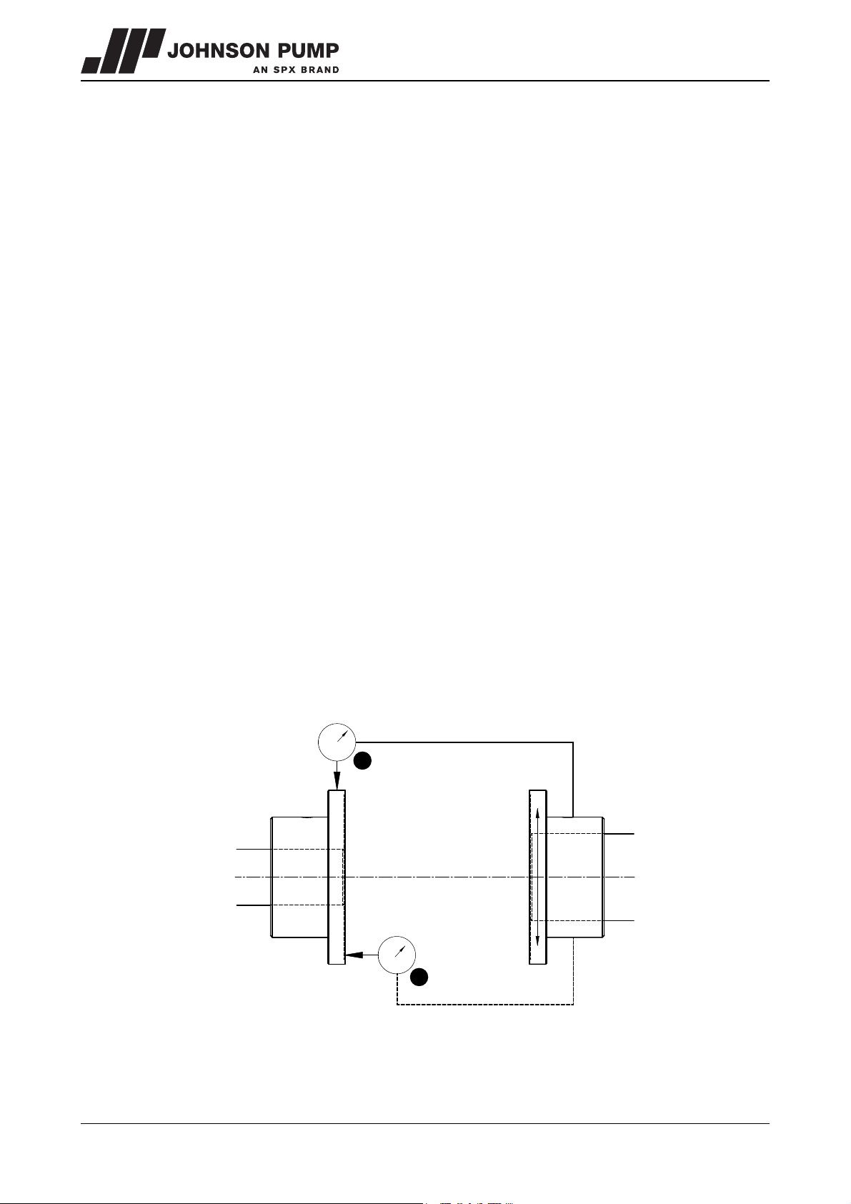
For couplings use a dial indicator as figure 3 shown. The alignment values are maximums
for continuous service, see paragraph 3.4.4 "Tolerances for aligning the coupling".
Figure 3: Aligning the coupling, A= Parallel, B= Angular.
20 Installation CR/EN (1004) 4.0
Page 22

CombiPro
Parallel alignment
1 Mount dial gauge (A) on the coupling halve motor side, see figure 3.
2 Make index lines on the two coupling halves.
3 Set the dial gauge pointer to zero, turn motor shaft 360 °.
4 Read dial gauge (A). Add or remove shims under the motor until the reading of the
dial gauge is within the allowable tolerance, see paragraph 3.4.4 "Tolerances for
aligning the coupling".
5 Repeat the procedure.
6 Remove dial gauge (A).
Angular alignment
1 Mount dial gauge (B) on the coupling halve motor side, see figure 3.
2 Make index lines on the two coupling halves.
3 Set the dial gauge pointer to zero, turn motor shaft 360 °.
4 Read dial gauge (B). Move the motor sideways until the deflection is halved, see
paragraph 3.4.4 "Tolerances for aligning the coupling".
5 Repeat the procedure.
6 Remove dial gauge (B).
7 Fit the guard. See paragraph 7.4.4 "Assembling the guard".
3.4.4 Tolerances for aligning the coupling
The maximum allowable tolerances for the alignment of the coupling halves are shown in
Ta bl e 2 .
Table 2: Alignment tolerances
External diameter of
coupling [mm]
86 1,0 0,30
105 1,3 0,35
130 1,5 0,45
152 2,0 0,55
The values are maximums for each type of misalignment. It is recommended that the
coupling is initially aligned to 10% of these values to allow for inevitable movements
during the life of the pump.
3.4.5 Grouting base plate
Use an approved, non-shrinking grout.
Axial
misalignment
[mm]
Max. Parallel
misalignment
[mm]
Grout manufacturer’s instructions should be consulted and followed!
Proceed as follow:
1 Align the base plate with sims under the base plate, see figure 4.
2 Build a strong wooden frame around the base plate to contain the grout.
3 Grout the the wooden frame to the underside of base plate. Allow grout to set.
4 Fill the base plate with grout. Allow grout to dry thoroughly before attaching piping to
pump (48 hours is sufficient time with approved grouting procedure).
CR/EN (1004) 4.0 Installation 21
Page 23

5 When the grout has thoroughly hardened, check the base plate bolt nuts and tighten
1
2
3
4
5
5
if necessary.
1Drain pan.
2 Wooden frame.
3Shims.
4 Basic foundation.
5Grout.
Figure 4: Grouting base plate.
3.5 Piping
• The piping to the suction and delivery connections must fit exactly and must not be
subject to stress during operation. For the maximum allowable forces and moments on
the pump flanges see paragraph 10.2 "Permissible forces and moments on the
flanges".
• The passage of the suction pipe must be amply dimensioned. This pipe should be as
short as possible and run towards the pump in such a way that no air pockets can
arise. If this is not possible, a venting facility should be provided at the highest point of
the pipe. If the inside diameter of the suction pipe is larger than the suction connection
of the pump, an eccentric reducer should be applied to prevent air pockets and whirls.
See figure 5.
Figure 5: Eccentric reducer to suction flange.
22 Installation CR/EN (1004) 4.0
• The maximum allowable system pressure is stated in paragraph 2.13 "Application
area". If there is a risk that this pressure might be exceeded, for instance because of
an excessive inlet pressure, appropriate measures should be taken by mounting a
safety valve in the piping.
Page 24

CombiPro
• Sudden changes in the rate of flow can lead to high pressure impulses in the pump
and the piping (water shock). Therefore, do not use quick-acting closing devices,
valves etc.
3.6 Accessories
• Fit any parts that may have been supplied separately.
• If the liquid does not flow towards the pump, fit a foot valve at the bottom of the
suction pipe. If necessary, combine this foot valve with a suction strainer to prevent
impurities from being drawn in.
• When mounting, place temporarily (for the first 24 operating hours) a fine gauze
between suction flange and suction pipe to prevent internal pump parts from being
damaged by foreign matter. If the risk of damage continues to exist, fit a permanent
filter.
• In case the pump is provided with a cooling chamber, connect the cooling chamber to
the supply and return lines of the cooling system.
3.7 Connection of the electric motor
The electric motor must be connected to the mains by an approved
electrician, according to the locally prevailing regulations of the electricity
company.
• Refer to the instruction manual belonging to the electric motor.
• If possible, fit a working switch as close as possible to the pump.
CR/EN (1004) 4.0 Installation 23
Page 25

24 Installation CR/EN (1004) 4.0
Page 26

CombiPro
4 Commissioning
4.1 Inspection of the pump
Check whether the pump shaft turns freely. Do this by turning the shaft end at the
coupling a few times by hand.
4.2 Inspection of the motor
Check whether the fuses have been mounted.
4.3 Pumps with oil-bath lubricated bearings
! Pumps provided with oil-bath lubricated bearings are shipped without oil and
must be filled with oil prior to commissioning the pump!
For the specification of the oil to be used, see paragraph 10.3 "Lubricants".
1 Remove the oil filler cap (2130).
2 Fill the bearing bracket through the oil filling orifice till the oil shows in the constant
level oiler.
3 Fit the oil filler cap.
4 Top up the constant level oiler entirely.
5 See the indication plate (see figure 6) for the right oil level.
Figure 6: Oil level indication.
CR/EN (1004) 4.0 Commissioning 25
Page 27

4.4 Preparing the pump unit for commissioning
Proceed as follows, both when the unit is put into operation for the first time and after the
pump has been overhauled.
1 Fully open the stop valve in the suction pipe. Close the delivery stop valve.
2 Fill the pump and the suction pipe with the liquid to be pumped.
3 Turn the pump shaft a few times by hand and add more liquid, if necessary.
4.5 Checking the sense of rotation
Beware of possible non-screened rotating parts, when checking the sense of
rotation!
1 The sense of rotation of the pump is indicated by an arrow. Check whether the sense
of rotation of the motor corresponds with that of the pump.
2 Let the motor run for only a short time and check the sense of rotation.
3 If the sense of rotation is not correct, alter the sense of rotation. See the instructions
in the user manual belonging to the electric motor.
4 Fit the guard.
4.6 Start-up
1 Open the stop valves in the supply and return lines for flushing or cooling liquid, if the
pump is connected to a flushing or cooling system. Ensure these systems are
switched on and set at the proper values.
2 Start the pump.
3 As soon as the pump is under pressure, slowly open the delivery stop valve until the
working pressure is attained.
4 Open the outlet valve fully until the pump reaches the correct duty point.
Make sure that when a pump is running, rotating parts are always properly
screened off by the guard!
4.7 Pump in operation
When the pump is in operation, pay attention to the following:
• The pump should never run dry.
• Never use a stop valve in the suction line to control pump output. The stop valve
should always be fully opened during operation.
• Check whether the absolute inlet pressure is sufficient, to prevent vaporization in the
pump.
• Check whether the pressure difference between suction and delivery side
corresponds with the specifications of the pump's duty point.
4.8 Noise
The noise production of a pump depends to a great extent on the operating conditions.
The values stated in paragraph 10.5 "Noise data" are based on normal operation of the
pump, driven by an electric motor. In case the pump is driven by a combustion engine, or
in case it is used outside the normal operation area, as well as in case of cavitation, the
noise level may exceed 85 dB(A). In that case precautions should be taken, like building
a noise-barrier around the unit or wearing hearing protection.
26 Commissioning CR/EN (1004) 4.0
Page 28

CombiPro
5 Maintenance
5.1 Daily maintenance
• Regularly check the oil level, see figure 7.
Figure 7: Oil level indication.
No water should get into the terminal box of the electric motor when the
pump room is sprayed clean! Never spray water on hot pump parts! The
sudden cooling down may cause them to burst and hot water may flow out!
5.2 Mechanical seal
A mechanical seal generally requires no maintenance, however, it should never be
allowed to run dry. If there are no problems, do not dismantle the mechanical seal. If a
mechanical seal shows any leakage it has to be replaced.
5.3 Lubrication of the bearings
• During operation the constant level oiler should never be empty. Take care to top up
timely.
• Frequency of oil change is dependent on pump service and environmental conditions.
As a general guide, oil in the bearing bracket should be changed every 4000
operating hours or at least every 6 month, after the initial change. For recommended
oils and quantities see paragraph 10.3 "Lubricants".
! Make sure the used oil is discharged safely.
See to it that it does not get into the environment.
CR/EN (1004) 4.0 Maintenance 27
Page 29

5.4 Environmental influences
• Regularly clean the filter in the suction pipe or the suction strainer at the bottom of the
suction pipe, as the inlet pressure may become too low if the filter or the suction
strainer is fouled.
• If there is a risk that the pumped liquid expands during solidification or freezing, the
pump has to be drained and, if necessary, flushed after it has been put out of service.
• If the pump is out of service for a long time, it has to be preserved.
5.5 Noise
If a pump starts making noise, this may point to certain problems with the pump unit. A
crackling noise can indicate cavitation or excessive motor noise can indicate
deterioration of the bearings.
5.6 Faults
The pump, of which you want to determine the fault, may be hot or under
pressure. Take the appropriate precautions first and protect yourself with
the proper safety devices (safety goggles, gloves, protective clothing)!
To determine the source of the malfunctioning of the pump, proceed as follows:
1 Switch off the power supply to the pump unit. Lock the working switch with a padlock
or remove the fuse. In case of a combustion engine: switch off the engine and close
the fuel supply to the engine.
2 Close the stop valves.
3 Determine the nature of the fault.
4 Try to determine the cause of the fault with chapter 6 "Problem solving" and take the
appropriate measures or contact your installer.
28 Maintenance CR/EN (1004) 4.0
Page 30

CombiPro
6 Problem solving
Faults in a pump installation can have various causes. The fault may not be in the pump, it
may also be caused by the pipe system or the operating conditions. Firstly, always check
that installation has been executed in accordance with the instructions in this manual and
that the operating conditions still correspond with the specifications for which the pump
was purchased.
In general, breakdowns in a pump installation are attributable to the following causes:
• Faults with the pump.
• Breakdowns or faults in the pipe system.
• Faults due to incorrect installation or commissioning.
• Faults due to incorrect choice of pump.
A number of the most frequently occurring failures as well as their possible causes are
shown in the table below.
Table 3: Most frequently occurring failures.
Most common faults Possible causes, see Table 4.
Pump delivers no liquid
Pump has insufficient volume flow
Pump has insufficient head 2 4 5 13 14 17 19 28 29
Pump stops after start up 1 2 3 4 5 6 7 8 9 10 11
Pump has higher power consumption than
normal
Pump has lower power consumption than
normal
Pump vibrates or is noisy
Bearings wear too much or become hot 23 24 25 26 27 37 38 39 40 42
Pump running rough hot or seizes 18 23 24 25 26 27 34 37 38 39 40 42
1 2 3 4 5 6 7 8 9 10 11 13 14 17 19 20
21 27 29
1 2 3 4 5 6 7 8 9 10 11 13 14 15 17 19
20 21 28 29
12 15 16 17 18 22 23 24 25 26 27 32
34 38 39
13 14 15 16 17 18 20 21 28 29
1 9 10 11 15 18 19 20 22 23 24 25 26
27 28 29 37 38 39 40
CR/EN (1004) 4.0 Problem solving 29
Page 31

Table 4: Possible causes of pump failures.
Possible causes
1 Pump or suction pipe is not sufficiently filled or de-aerated
2 Gas or air coming from the liquid
3 Air lock in the suction pipe
4 Air leak in the suction pipe
8 The manometric suction head is too high
9 Suction pipe or suction strainer is blocked
10 Insufficient immersion of foot valve or suction pipe during operation of the pump
11 NPSH available too low
12 Speed too high
13 Speed too low
14 Wrong sense of rotation
15 Pump does not operate at the right duty point
16 Liquid density differs from the calculated liquid density
17 Liquid viscosity differs from the calculated liquid viscosity
18 Pump operates when the liquid flow is too low
19 Wrong pump selection
20 Obstruction in impeller or pump casing
21 Obstruction in the piping
22 Wrong installation of the pump unit
23 Pump and motor not well aligned
24 Rotating part running out of true
25 Imbalance in rotating parts (for instance: impeller or coupling)
26 Pump shaft is running out of true
27 Bearings faulty or worn out
28 Casing wear ring faulty or worn out
29 Damaged impeller
37 Axial retaining of impeller or pump shaft is defective
38 The bearings have been mounted wrongly
39 Too much or too little bearing lubrication
40 Wrong or polluted lubricant
41 Impurities in the liquid get into the stuffing box packing
42 Too high axial force because of worn dorsal blades or excessive inlet pressure
30 Problem solving CR/EN (1004) 4.0
Page 32

CombiPro
7 Disassembly and assembly
7.1 Precautionary measures
Take adequate measures to avoid that the motor is started while you are
working on the pump. This is especially important for electric motors with
remote control:
• Switch the operating switch near the pump (if available) to "OFF".
• Switch off the pump switch on the switchboard.
• If necessary remove the fuses.
• Hang a danger board near the switchboard cabinet.
7.2 Special tools
Assembly and disassembly work requires no special tools. However, such tools can
make certain jobs easier, for instance replacing the shaft seal. If such is the case it will be
indicated in the text.
7.3 Draining
! Make sure no liquid or oil gets into the environment!
7.3.1 Liquid draining
Before starting any disassembly the pump should be drained.
1 If necessary, close the valves in the suction and delivery pipe and in the flushing or
cooling supply lines to the shaft seal.
2 Remove the blind flange (1930).
3 If harmful liquids are pumped wear protective gloves, shoes, glasses, etc., and
thoroughly flush the pump.
4 Refit the blind flange.
7.3.2 Oil draining
If the pump is designed with oil lubricated bearings:
1 Remove the magnetic drain plug (2150).
2 Drain the oil.
3 Refit the magnetic drain plug.
If possible, wear protective gloves. Regular contact with oil products may
result in allergic reactions.
CR/EN (1004) 4.0 Disassembly and assembly 31
Page 33

7.4 Back-Pull-Out system
0140
2100081008050110
0820
The pumps are designed with a Back-Pull-Out system. The pump unit is designed with a
spacer-coupling, the spacer of this coupling can easily be removed. After that the
bearing bracket with the entire rotating part can be removed. This means that almost the
whole pump can be dismantled without having to detach the suction and delivery piping.
The motor remains in its position.
7.4.1 Disassembling the guard
1 Loosen bolts (0237) and remove these. See figure 9.
2 Remove the guard (0270).
7.4.2 Disassembling the Back-Pull-Out unit
Figure 8: Back-Pull-Out principle.
1 Remove the spacer.
2 Disconnect possible flushing and/or cooling lines.
3 Loosen the bracket support (0140) from the base plate, see figure 8.
4 Remove the nuts (0810) and washers (0805). Tighten alternately both bolts (0820)
until the pump cover (0110) is released.
5 Pull the entire bearing bracket (2100) from the pump casing. The entire bearing
bracket of large pumps is very heavy. Support it with a beam or hang it in a pulley
sling.
6 Remove the coupling half from the pump shaft and remove the coupling key (2210).
7.4.3 Assembling the Back-Pull-Out unit
1 Fit a new gasket (0300) into the pump casing and fit the entire bearing bracket back
into the pump casing. Place washers (0805) and tighten the nuts (0810) crosswise.
For tightening moment of the nuts see paragraph 10.1.3 "Torques settings for nuts for
pump casing".
2 Fix the bracket support (0140) on the base plate.
3 Reconnect the flushing and/or cooling lines.
4 Fit the coupling key (2210) and fit the coupling half onto the pump shaft.
5 Fit the spacer of the spacer coupling.
6 Check the alignment of pump and motor shaft, see paragraph 3.4.3 "Alignment of the
coupling". If necessary, realign.
32 Disassembly and assembly CR/EN (1004) 4.0
Page 34

CombiPro
0270
0237
7.4.4 Assembling the guard
1 Place the guard (0270) on the coupling.
2 Fit the guard with bolts (0237).
Figure 9: Fitting the guard.
7.5 Replacing the impeller and the wear ring
If the play has risen to 0,9 mm or greater due to wear then both wear rings are replaced.
7.5.1 Disassembling the impeller
1 Remove the Back-Pull-Out unit, see paragraph 7.4.2 "Disassembling the Back-Pull-
Out unit".
2 Unlock the set screw (1825) and remove the cap nut (1820).
3 Remove the impeller (0120) with a pulley puller, or wrest the impeller by inserting for
instance 2 big screwdrivers between the impeller and the pump cover (0110).
4 Remove the impeller key (1860).
7.5.2 Mounting the impeller
1 Place the impeller key (1860) in the key way of the pump shaft.
2 Push the impeller onto the pump shaft.
3 Fit the cap nut. For tightening moment of the nut see paragraph 10.1.2 "Tightening
moments for cap nut".
4 Fit the set screw (1825).
CR/EN (1004) 4.0 Disassembly and assembly 33
Page 35

7.5.3 Disassembling the wear rings
b
d
AB
CD
b
d
After removing the Back-Pull-Out unit (see paragraph 7.4.2 "Disassembling the BackPull-Out unit") the wear rings can be removed. In most cases the ring has been fixed so
tightly that it cannot be removed undamaged.
Figure 10: Removal of wear ring.
1 Disassembling the impeller, see paragraph 7.5.1 "Disassembling the impeller"
2 Unlock the set screw (0155) that lock up the impeller wear ring (0150) on the
impeller.
3 Unlock the set screw (0135) that lock up the casing wear ring (0130) on the impeller.
4 Measure the thickness (d) and the width (b) of the ring, see figure 10 A.
5 Make a centre hole in the middle of the edge of the ring at two opposite points, see
figure 10 B.
6 Use a drill with a diameter just a little bit smaller than the thickness (d) of the ring and
drill two holes in the ring, see figure 10 C. Don't drill deeper than the width (b) of the
ring. Take care not to damage the fitting edges of the pump casing and impeller.
7 Use a chisel to cut the remaining part of the ring thickness. Now you can remove the
ring in two parts from the pump casing, see figure 10 D.
8 Clean the pump casing and impeller and carefully remove all bore dust and metal
splinters.
34 Disassembly and assembly CR/EN (1004) 4.0
Page 36

CombiPro
7.5.4 Assembling the wear rings
1 Clean and degrease the fitting edge of the pump casing and impeller where the wear
ring is to be mounted.
2 Fit the casing wear ring in the pump casing. Take care it is not pushed out of
alignment!
3 Fit the impeller wear ring on the impeller. Take care it is not pushed out of
alignment!
! Make sure that they are not inserted obliquely!
4 Both wear rings then have to be secured. Drill 3 holes Ø5 mm, 9 mm deep, right on
the seam between impeller and wear ring c.q. pump casing and wear ring.
Subsequently cut screw thread M6 (see figure 11).
5 Fit the set screws (0135 and 0155) in their positions in the impeller and the pump
casing respectively.
! Don’t fasten the set screws too tight, in order to avoid deformation of the wear
rings!
Whenever an impeller has new wear rings fitted it must be dynamically
balanced before being reassembled!
Figure 11: Locking the wear ring.
CR/EN (1004) 4.0 Disassembly and assembly 35
Page 37

7.6 Mechanical seal
7.6.1 Instructions for mounting a cartridge seal
➢ First read the following instructions regarding mounting a cartridge seal. Follow these
instructions closely when mounting a cartridge seal.
• This mechanical seal comes as a ’full cartridge seal’. This means that this mechanical
seal must be mounted as one single piece and that it shall NOT be taken apart!
• A cartridge seal is a fragile precision instrument. Leave the cartridge seal in its original
packing until you are ready to mount it!
• Clean all receiving parts properly. Make sure your hands and working environment are
clean!
7.6.2 Disassembling a cartridge seal
1 Re-fit the centering tabs on the cover of the seal cartridge into the groove in the seal
collar in order to immobilise the cartridge seal.
2 Disassemble the impeller, see paragraph 7.5.1 "Disassembling the impeller".
3 Remove the nuts (1810) and washers (1805) and pull the seal cartridge backwards
towards the bearing bracket (2100).
4 Remove the Allen screws (0850) and washer (0855) and knock the pump cover
loose from the bearing bracket.
5 Pull the entire seal cartridge from the pump shaft.
7.6.3 Mounting a cartridge seal
1 Put the bearing bracket in upright position (impeller side up).
2 Push the seal cartridge onto the pump shaft.
3 Mount the pump cover (0110) in the correct position in the fitting edge of the bearing
bracket (2100). Check whether the pump cover is at right angles to the pump
shaft. Place washers (0855) fasten the pump cover with Allen screw (0850).
4 Mount the seal cartridge to the pump cover (0110). Check the position in view of the
connection points. Place washers (0805) fasten the seal cartridge with nuts (0810).
5 Fit the impeller and other parts, see paragraph 7.5.2 "Mounting the impeller" and
paragraph 7.4.3 "Assembling the Back-Pull-Out unit".
6 Release the centering tabs of the seal cartridge, turn them halfway round and secure
them again against the seal cover. The shaft must now be able to rotate freely.
36 Disassembly and assembly CR/EN (1004) 4.0
Page 38

CombiPro
7.7 Bearing
7.7.1 Instructions for assembly and disassembly of bearings
➢ First read the following instructions regarding assembly and disassembly. Follow these
instructions closely when assembling and disassembling bearings.
Disassembly:
•Use a proper puller to remove the bearings from the pump shaft.
• If no proper puller is available, carefully knock at the inner raceway of the bearing. Use
an ordinary hammer and a mild steel drift for this.
Never knock at the bearing with a hammer!
Assembly:
• Make sure your working place is clean.
• Leave the bearings in their original packing as long as possible.
• Make sure the pump shaft and the bearing seats do have a smooth surface, free of
burrs.
• Slightly oil the pump shaft and the other relevant parts before assembly.
• Preheat the bearings to 90°C before mounting them on the pump shaft.
• If preheating is not possible: knock the bearing onto the pump shaft. Never knock at
the bearing directly! Use a mounting bush positioned against the inner raceway of
the bearing and a normal hammer (a soft hammer might loose some splinters which
could damage the bearing).
• Always apply a new locking washer (2570) when assembling bearings!
7.7.2 Disassembling bearing
1 Dismantle the impeller and the shaft seal, see paragraph 7.5.1 "Disassembling the
impeller" and paragraph 7.6.2 "Disassembling a cartridge seal".
2 Remove the deflector (2220).
3 Remove the coupling with a coupling puller and remove the coupling key (2210).
4 Remove the deflector (2180).
5 Unscrew the Allen screws (2810 and 2815) and remove the bearing covers (2110
and 2115). Remove the gaskets (2160).
6 Knock at the pump shaft (2200) at the impeller side to loosen the bearings from the
bearing bracket. Use a plastic hammer to avoid damage to the thread.
7 Remove the inner circlip (2300).
8 Knock the lip of the locking washer (2570) out of the lock nut (2560) and loosen the
lock nut.
9 Remove the bearings from the pump shaft.
CR/EN (1004) 4.0 Disassembly and assembly 37
Page 39

7.7.3 Assembling bearing
1 Clean the interior of the bearing bracket properly.
2 Preheat the angular contact ball bearings and the inner ring of the cylindrical roller
bearing and fit them onto the pump shaft. Make sure they are positioned straight on
the pump shaft and push them firmly against the shaft shoulder. The cylindrical roller
bearing (2250) is fitted at the impeller side. The angular contact ball bearings are
fitted in O-position at the drive side. Ensure that the bearings are fitted straight on
the pump shaft. Let the bearings cool down!
3 Fit the locking washer (2570) and screw the lock nut (2560) on the pump shaft.
Tighten the lock nut and lock it by knocking a lip of the locking washer into the
opening of the lock nut.
4 Fit the inner circlip (2300) into the bearing bracket (2100).
5 Fit the pump shaft with bearings, starting from the motor side, in the bearing bracket.
Knock at the shaft end at the coupling side until the foremost bearing (2260) slides
through the bearing bore. After each knock rotate the pump shaft one turn to prevent
bearing damage.
6 Fit the outer ring of the cylindrical roller bearing. This ring should go into the bearing
bracket straight.
7 Check to ensure that the oil catchers (2120 and 2125) are undamaged. Replace
them if necessary.
8 Fit the bearing covers (2110 and 2115) with gaskets (2160) and fix them with Allen
screws (2810 and 2815).
9 Fit the deflector (2180 and 2220).
10 Fit the shaft seal and the impeller, see paragraph 7.6.3 "Mounting a cartridge seal"
and paragraph 7.5.2 "Mounting the impeller".
38 Disassembly and assembly CR/EN (1004) 4.0
Page 40

CombiPro
DN1
DN2
ab
ad
ah
ajx al
aa
ac
ag
aix ak
af
an
vk
vv
vb
vc
db
zd
vf
vj
ed
eb h9
ec
vd
zb
tb
am
ve
va
mgea
vi
14
10
BM
BV
BE
BD
DN3
gg
gc
ga
gix gk
gm
ae
zn
zl
DN1
zc
DN2
DN3
BN
∅
∅
∅
∅
∅
8Dimensions
8.1 Pump dimensions
Figure 12: Pump dimensions.
Connections
BM Oil drain ½ BSP
BV Oil filling plug ½ NPT
Connections (optional)
CR/EN (1004) 4.0 Dimensions 39
BD Inlet oil chamber jacket ½ NPT
BE Outlet oil chamber jacket ½ NPT
BN Drain oil chamber jacket ½ NPT
Page 41

8.2 Flange dimensions
8.2.1 Flange dimensions ASME B16.5 150lbs (ISO7005 PN20)
DN1 - DN2
aa ab ac ad ae af ag ah aixak ajxal am an
50 (2") 40 (1½") 92 73 120,5 98,5 165 156 4x18 4x16 22 21
80 (3") 50 (2") 127 92 152,5 120,5 210 165 4x18 4x18 29 22
100 (4") 80 (3") 157 127 190,5 152,5 254 210 8x18 4x18 32 29
150 (6") 100 (4") 216 157 241,5 190,5 318 254 8x22 8x18 37 32
200 (8") 150 (6") 270 216 298,5 241,5 381 318 8x22 8x22 41 37
DN3
ga gc ge gg gixgk gm
15,8 (½") 34,9 60,3 90 4x15,9 11,2
20,9 (¾") 42,9 69,9 100 4x15,9 12,7
8.2.2 Flange dimensions ASME B16.5 300lbs (ISO7005 PN50)
DN1 - DN2
aa ab ac ad ae af ag ah aixak ajxal am an
50 (2") 40 (1½") 92 73 127 114,5 165 156 8x18 4x22 22 21
80 (3") 50 (2") 127 92 168,5 127 210 165 8x22 8x18 29 22
100 (4") 80 (3") 157 127 200 168,5 254 210 8x22 8x22 32 29
150 (6") 100 (4") 216 157 270 200 318 254 12x22 8x22 37 32
200 (8") 150 (6") 270 216 330 270 381 318 12x26 12x22 41 37
DN3
ga gc ge gg gixgk gm
15,8 (½") 34,9 66,7 95 4x15,9 14,3
20,9 (¾") 42,9 82,6 115 4x19,1 15,9
40 Dimensions CR/EN (1004) 4.0
Page 42

CombiPro
8.3 Pump dimensions
aa ab ga db ea eb ec ed mg tb va vb vc vd ve vf vi vj vk vv zb zc zd zl* zn* [kg]
40A-125 140 50 8 27 24 100 511 100 270 320 60 20 314 160 190 100 411 300 - - - - 52
40A-160 140 50 8 27 24 100 511 100 300 350 18 60 20 314 50 160 190 100 411 320 - - - - 60
40AA-160 50 40 15,8 140 50 8 27 24 100 511 100 300 350 18 60 20 314 50 160 190 100 411 320 - - - - 60
40A-200 160 50 8 27 24 100 511 100 350 400 60 25 314 160 190 100 411 360 - - - - 70
40A-250 180 80 10 35 32 100 634,5 100 400 450 60 25 378 160 190 125 509,5 405 - - - - 118
50A-125 140 50 8 27 24 100 511 100 280 330 50 20 314 160 190 100 411 300 - - - - 59
50A-160 140 50 8 27 24 100 511 100 300 350 60 20 314 160 190 100 411 320 - - - - 66
50A-200 80 50 15,8 160 50 8 27 24 100 511 100 350 400 18 60 25 314 50 160 190 100 411 350 - - - - 78
50A-250 180 80 10 35 32 100 634,5 100 400 450 50 25 378 160 190 125 509,5 430 - - - - 122
50A-315 200 80 10 35 32 120 634,5 120 470 520 60 30 378 190 230 125 509,5 480 - - - - 130
50AA-315 200 80 10 35 32 120 634,5 120 470 520 60 30 378 190 230 125 509,5 480 - - - - 130
50B-125 50 8 27 24 100 511 100 300 350 50 20 314 160 190 100 411 300 - - - - 58
50B-160 160 50 8 27 24 100 511 100 330 380 50 20 314 160 190 100 411 360 - - - - 64
50B-200 160 50 8 27 24 100 536 100 350 400 18 50 25 314 50 160 190 125 411 385 - - - - 79
50BA-200 80 50 15,8 160 50 8 27 24 100 536 100 350 400 18 50 25 314 50 160 190 125 411 385 - - - - 79
50B-250 180 80 10 35 32 100 634,5 100 400 450 50 25 378 160 190 125 509,5 430 - - - - 101
50BC-250 180 80 10 35 32 100 634,5 100 400 450 50 25 378 160 190 125 509,5 430 - - - - 101
50B-315 225 80 10 35 32 120 634,5 120 470 520 60 30 378 190 230 125 509,5 505 - - - - 138
80A-125 160 50 8 27 24 120 511 120 355 420 60 25 314 160 190 100 411 340 - - - - 67
80A-160 160 80 10 35 32 120 609,5 120 375 440 60 25 378 160 190 100 509,5 360 - - - - 105
80A-200 100 80 20,9 180 80 10 35 32 120 609,5 120 415 480 22 60 25 378 65 160 190 100 509,5 405 - - - - 111
80A-250 200 80 10 35 32 120 634,5 120 455 520 60 25 378 190 230 125 509,5 450 - - - - 140
80AA-250 200 80 10 35 32 120 634,5 120 455 520 60 25 378 190 230 125 509,5 450 - - - - 140
80A-315 225 110 12 45 42 120 676 120 480 545 60 30 385 190 230 125 551 505 - - - - 180
100A-160 180 80 10 35 32 120 634,5 120 455 520 60 25 378 160 190 125 509,5 405 - - - - 131
100A-200 180 80 10 35 32 120 634,5 120 455 520 60 25 378 160 190 125 509,5 430 - - - - 140
100A-250 225 80 10 35 32 120 634,5 120 485 550 22 70 25 378 65 190 230 125 509,5 505 - - - - 160
100AA-250 150 100 20,9 225 80 10 35 32 120 634,5 120 485 550 22 70 25 378 65 190 230 125 509,5 505 - - - - 160
100A-315 250 110 12 45 42 120 691 120 535 600 60 30 385 190 230 140 551 565 - - - - 207
100AA-315 250 110 12 45 42 120 691 120 535 600 60 30 385 190 230 140 551 565 - - - - 207
100A-400 280 110 12 45 42 120 691 120 635 700 60 30 385 190 230 140 551 635 - - - - 265
100AA-400 280 110 12 45 42 120 691 120 635 700 60 30 385 190 230 140 551 635 - - - - 265
100B-200 200 80 10 35 32 120 649,5 120 515 580 60 25 378 190 230 140 509,5 480 - - - - 135
100BC-200 200 80 10 35 32 120 649,5 120 515 580 60 25 378 190 230 140 509,5 480 - - - - 135
100B-250 150 100 20,9 225 110 12 45 42 120 651 120 535 600 22 60 25 385 65 190 230 140 551 505 - - - - 178
100B-315 250 110 12 45 42 120 691 120 535 620 60 30 385 190 230 140 551 565 - - - - 204
100BA-315 250 110 12 45 42 120 691 120 535 620 60 30 385 190 230 140 551 565 - - - - 204
100B-400 280 110 12 45 42 120 691 120 620 700 60 30 385 190 230 140 551 695 - - - - 272
150A-250 250 110 12 45 42 140 691 140 600 680 70 25 385 190 230 140 551 605 - - - - 221
150A-315 200 150 20,9 280 110 12 45 42 140 691 140 620 700 22 70 30 385 80 190 230 140 551 635 - - - - 246
150A-400 315 110 12 45 42 140 691 140 670 750 70 30 385 190 230 140 551 715 - - - - 308
8.4 Pump-motor unit
For dimension see GAD enclosed with the delivery.
CR/EN (1004) 4.0 Dimensions 41
Page 43

42 Dimensions CR/EN (1004) 4.0
Page 44

CombiPro
9Parts
9.1 Ordering parts
9.1.1 Order form
You can use the order form included in this manual for ordering parts.
When ordering parts always quote the following data:
1Your address.
2 The quantity, the item number and the description of the part.
3 The pump number. The pump number is stated on the label on the cover of this
manual and on the type plate of the pump.
4 In the event of different electric motor voltage you should state the correct voltage.
9.1.2 Recommended spare parts
Parts marked with a
1)
Start-up spares
2)
Initial spare parts (one year operation)
3)
Normal spare parts (two years operation)
1), 2), 3)
are recommended spare parts.
CR/EN (1004) 4.0 Parts 43
Page 45

0810
0276
0235
0236
2145
2135
2420/2425
2130
2210
2200
2100
2820
2830
2810
1860
2300
2160
0140
2150
2410/2415
0805
0800
0820
0850
0855
1905
1930
2815
2140
2400/2405
2190
2250
2160
2570
0150
0155
0135
0130
1820
1825
2260
0100
1920
1915
2155
1900
2180
2560 2125
2115
2120
2110
1950
0120
0110
1800
1805 0300
1810
2190
2220
0239
9.2 Pump
9.2.1 Sectional drawing pump
Figure 13: Sectional drawing pump.
44 Parts CR/EN (1004) 4.0
Page 46

CombiPro
9.2.2 Parts list pump
Item Quantity Description
S-1 S-6 S-8 C-6 A-8
API-610 Material Classes
0100 1 pump casing carbon steel chrome steel stainless steel
0110 1 pump cover carbon steel chrome steel stainless steel
0120
0130
3)
1)2)3)
1 impeller cast iron chrome steel stainless steel chrome steel stainless steel
1 casing wear ring chrome steel stainless steel chrome steel stainless steel
0135 3 set screw stainless steel
0140 1 bracket support steel
0150
1)2)3)
1 impeller wear ring chrome steel stainless steel chrome steel stainless steel
0155 3 set screw stainless steel
0235 1 bolt stainless steel
0236 1 washer stainless steel
0239 1 washer spring steel
0276 1 seal guard stainless steel
0300
1)2)3)
1 gasket stainless steel/graphite
0800 ** stud carbon steel
0805 ** washer steel
0810 ** nut carbon steel
0820 2 bolt stainless steel
0850 *** Allen screw stainless steel
0855 *** washer stainless steel
1800 4 stud stainless steel
1805 4 washer stainless steel
1810 4 nut stainless steel
1820
1825
1860
3)
3)
3)
1 cap nut 4140 steel stainless steel chrome steel stainless steel
1 set screw stainless steel
1 impeller key stainless steel
1900 4 stud bolt carbon steel
1905 8 washer carbon steel
1915 1 elbow carbon steel stainless steel
1920 1 welding neck flange carbon steel stainless steel
1930 1 blind flange carbon steel stainless steel
1950 1 gasket stainless steel/graphite
2100 1 bearing bracket carbon steel
2110 1 bearing cover stainless steel
2115 1 bearing cover stainless steel
2120
2125
3)
3)
1 oil catcher bronze
1 oil catcher bronze
2130 1 oil filler cap stainless steel
2135 1 wire cage steel
2140 1 constant level oiler - 2145 1 oil sight glass - 2150 1 magnetic drain plug steel
2155 1 gasket gylon
2160
3)
2 gasket - -
2180 1 deflector rubber
CR/EN (1004) 4.0 Parts 45
Page 47

Item Quantity Description
S-1 S-6 S-8 C-6 A-8
API-610 Material Classes
2190 2**** set screw stainless steel
2200
2210
3)
3)
1pump shaft
4140 steel
1 coupling key steel
*)
stainless steel chrome steel stainless steel
2220 1 deflector rubber
2250
2260
2)3)
2)3)
1 cylindrical roller bearing - -
angular contact ball
2
bearing
- -
2300 1 inner circlip spring steel
2400 1 name plate stainless steel
2405 2 rivet stainless steel
2410 1 arrow plate aluminium
2415 2 rivet stainless steel
2420 1 oil level plate stainless steel
2425 2 rivet stainless steel
2560
2570
3)
3)
1 lock nut steel
1 locking washer steel
2810 4 Allen screw stainless steel
2815 4 Allen screw stainless steel
2820 2 Allen screw stainless steel
2830 2 washer stainless steel
* For Class S-6, the standard shaft material for boiler feed service and for liquid
temperatures above 175°C is chrome steel
** Quantity depends on pump type
*** Quantity depends on bearing group
**** For bearing group 3 quantity 1
46 Parts CR/EN (1004) 4.0
Page 48

CombiPro
1410
1420
1400
1430
1460
1504
9.3 Mechanical seal piping plan 11 - tubing
9.3.1 Drawing plan 11 - tubing
Figure 14: Drawing plan 11 - tubing.
9.3.2 Parts list plan 11 - tubing
Item Quantity Description
1400 1 pipe nipple stainless steel
1410 1 female connector stainless steel
1420 1 pipe stainless steel
1430 1 female connector stainless steel
1460 1 pipe nipple stainless steel
1504 1 orifice stainless steel
S-1 S-6 S-8 C-6 A-8
API-610 Material Classes
CR/EN (1004) 4.0 Parts 47
Page 49

9.4 Mechanical seal piping plan 11 - flanged
2060
203
0
2080
2035
205
0
202
5
2070201
0
2050
200
0
2030
2035
2020
2060
2015
2040
9.4.1 Drawing plan 11 - flanged
Figure 15: Drawing plan 11 - flanged.
9.4.2 Parts list plan 11 - flanged
Item Quantity Description
2000 4 stud bolt carbon steel
2010 1
2015 1 pipe stainless steel
2020 1 welding neck flange carbon steel stainless steel
2025 1 orifice stainless steel
2030 2 welding neck flange stainless steel
2035 16 washer carbon steel
2040 4 stud bolt carbon steel
1)2)3)
2050
2060 2 elbow stainless steel
2070 1 pipe carbon steel stainless steel
2080 1 orifice plate stainless steel
welding neck flange + pipe
nipple
3 gasket stainless steel
S-1 S-6 S-8 C-6 A-8
API-610 Material Classes
stainless steel
48 Parts CR/EN (1004) 4.0
Page 50

CombiPro
2860
28502840
03400340
28450330
9.5 Oil chamber jacket
9.5.1 Drawing oil chamber jacket
Figure 16: Drawing oil chamber jacket.
9.5.2 Parts list oil chamber jacket
Item Quantity Description
0330 1 plug stainless steel
0340 2 plug stainless steel
2840 6 bolt stainless steel
2845 6 washer stainless steel
2850 1 oil chamber jacket carbon steel
2860
1)2)3)
1 gasket - -
API-610 Material Classes
S-1 S-6 S-8 C-6 A-8
CR/EN (1004) 4.0 Parts 49
Page 51

9.6 Pump casing jacket
0100
9.6.1 Drawing pump casing jacket
Figure 17: Drawing pump casing jacket.
9.6.2 Parts list pump casing jacket
Item Quantity Description
0100 1 pump casing jacket carbon steel stainless steel
API-610 Material Classes
S-1 S-6 S-8 C-6 A-8
50 Parts CR/EN (1004) 4.0
Page 52

CombiPro
10 Technical data
10.1 Tightening moments
10.1.1 Tightening moments for bolts and nuts
! For nuts for pump casing (item 0810), see paragraph 10.1.3 "Torques settings
for nuts for pump casing"!
Table 5: Tightening moments for bolts and nuts.
Materials 8.8 A2, A4
Thread Tightening moment [Nm]
M6 9 6
M8 20 14
M10 40 25
M12 69 43
M16 168 105
10.1.2 Tightening moments for cap nut
Table 6: Tightening moments for cap nut (1820).
Size Tightening moment [Nm]
M12 43
M16 105
M24 220
CR/EN (1004) 4.0 Technical data 51
Page 53

10.1.3 Torques settings for nuts for pump casing
Table 7: Torques settings for nuts (0810) for pump casing
Bearing group Size
40A-125 1 M10 (8x) 40 47
40A-160 1 M12 (8x) 69 80
40AA-160 1 M12 (8x) 69 80
40A-200 1 M12 (8x) 71 83
40A-250 2 M12 (12x) 71 82
50A-125 1 M10 (8x) 40 47
50A-160 1 M12 (8x) 69 80
50A-200 1 M12 (8x) 71 83
50A-250 2 M12 (12x) 71 82
50A-315 2 M16 (8x) 167 194
50AA-315 2 M16 (8x) 167 194
50B-125 1 M10 (8x) 40 46
50B-160 1 M12 (8x) 67 77
50B-200 1 M12 (8x) 71 83
50BA-200 1 M12 (8x) 71 83
50B-250 2 M12 (12x) 71 82
50BC-250 2 M12 (12x) 71 82
50B-315 2 M16 (8x) 168 196
80A-125 1 M10 (8x) 40 46
80A-160 2 M12 (8x) 67 77
80A-200 2 M12 (8x) 70 82
80A-250 2 M12 (12x) 69 80
80AA-250 2 M12 (12x) 69 80
80A-315 3 M16 (8x) 171 199
100A-160 2 M12 (8x) 67 77
100A-200 2 M12 (8x) 70 81
100A-250 2 M12 (12x) 70 81
100AA-250 2 M12 (12x) 70 81
100A-315 3 M16 (8x) 168 196
100A-400 3 M16 (12x) 165 192
100AA-400 3 M16 (12x) 165 192
100B-200 2 M12 (8x) 70 81
100BC-200 2 M12 (8x) 70 81
100B-250 3 M12 (12x) 69 79
100B-315 3 M16 (8x) 168 195
100B-400 3 M16 (12x) 172 200
150A-250 3 M12 (12x) 69 79
150A-315 3 M16 (8x) 169 197
150A-400 3 M16 (12x) 172 200
Lubricated Not-lubricated
[Nm] [Nm]
52 Technical data CR/EN (1004) 4.0
Page 54

CombiPro
Y
X
Z
Y
X
Z
Y
X
10.2 Permissible forces and moments on the flanges
Forces and moments acting on the pump flanges due to pipe loads can cause
misalignment of the pump and driver shafts, deformation and overstressing of the pump
casing, or overstressing of the fixing bolts between the pump and the base plate.
Z
Figure 18: Coordinate system.
CR/EN (1004) 4.0 Technical data 53
Page 55

10.2.1 Allowable forces and moments on suction and discharge flanges
Table 8: According API 610 - table 4 "Nozzle loadings"
Allowable forces
[N]
Allowable moments
[Nm]
Allowable forces
[N]
Allowable moments
[Nm]
Suction Discharge
FyF
F
x
FrMxMyMzMrF
z
FyFzFrMxMyMzM
x
40A-125
40A-160
40AA-160 890 710 580 1280 460 230 350 620 710 580 890 1280 460 230 350 620
40A-200
40A-250
50A-125
50A-160
50A-200 1330 1070 890 1930 950 470 720 1280 710 580 890 1280 460 230 350 620
50A-250
50A-315
50AA-315
50B-125
50B-160
50B-200
50BA-200 1330 1070 890 1930 950 470 720 1280 710 580 890 1280 460 230 350 620
50B-250
50BC-250
50B-315
80A-125
80A-160
80A-200 1780 1420 1160 2560 1330 680 1000 1800 1070 890 1330 1930 950 470 720 1280
80A-250
80AA-250
80A-315
100A-160
100A-200
100A-250
100AA-250 3110 2490 2050 4480 2300 1180 1760 3130 1420 1160 1780 2560 1330 680 1000 1800
100A-315
100AA-315
100A-400
100AA-400
100B-200
100BC-200
100B-250 3110 2490 2050 4480 2300 1180 1760 3130 1420 1160 1780 2560 1330 680 1000 1800
100B-315
100BA-315
100B-400
150A-250
150A-315 4890 3780 3110 6920 3530 1760 2580 4710 2490 2050 3110 4480 2300 1180 1760 3130
150A-400
r
Pump mounted on a grouted base plate of carbon steel
Fr, Mr = resultant
54 Technical data CR/EN (1004) 4.0
Page 56

CombiPro
10.2.2 Allowable forces and moments on the drain flange
Table 9: According API 610 - table 4 "Nozzle loadings"
Allowable forces [N] Allowable moments [Nm]
F
F
x
F
y
F
z
M
r
M
x
M
y
z
890 710 580 1280 460 230 350 620
Pump mounted on a grouted base plate of carbon steel
Fr, Mr = resultant
10.3 Lubricants
10.3.1 Oil
Table 10: Recommended oils according to ISO VG 68 classification for ambient
temperatures above 15 °C.
BP Energol HLP-HM 68
CHEVRON Rando HDZ 68
CHEVRON Regal Premium EP 68
EXXONMOBIL Mobil D.T.E. Oil Heavy Medium
EXXONMOBIL Teresstic T 68
SHELL Tel l u s 6 8
TOTAL Azolla ZS 68
M
r
10.3.2 Oil contents
Table 11: Oil contents.
Bearing group Oil contents [litres]
1 0,40
2 0,50
3 0,60
CR/EN (1004) 4.0 Technical data 55
Page 57

10.4 Hydraulic performance
10.4.1 Performance overview cast steel material class S-1
Figure 19: Performance overview 3000 min
-1
.
-1
Figure 20: Performance overview 1500 min
.
56 Technical data CR/EN (1004) 4.0
Page 58

CombiPro
Figure 21: Performance overview 3600 min-1.
Figure 22: Performance overview 1800 min
CR/EN (1004) 4.0 Technical data 57
-1
.
Page 59

10.4.2 Performance overview material classes S-6, S-8, C-6, A-8
Figure 23: Performance overview 3000 min
-1
.
Figure 24: Performance overview 1500 min
-1
.
58 Technical data CR/EN (1004) 4.0
Page 60

CombiPro
Figure 25: Performance overview 3600 min-1.
Figure 26: Performance overview 1800 min
CR/EN (1004) 4.0 Technical data 59
-1
.
Page 61

10.5 Noise data
54
56
58
60
62
64
66
68
70
72
74
76
78
80
82
84
86
88
90
92
94
96
98
0,1
1
10
100
200
P [kW]
[dB(A)]
A
4103_A
B
60
65
70
75
80
85
90
95
100
0,1
1
10
100
300
P [kW]
[dB(A)]
4104_A
A
B
10.5.1 Pump noise as a function of pump power
Figure 27: Noise level as function of pump power [kW] at 1450 min
-1
A = sound energy, B = sound pressure.
Figure 28: Noise level as function of pump power [kW] at 2900 min
A = sound energy, B = sound pressure.
60 Technical data CR/EN (1004) 4.0
-1
Page 62

CombiPro
4102
L [dB]
|L1 - L2| [dB]
01234567891011121314151617181920
3,2
3,0
2,8
2,6
2,4
2,2
2,0
1,8
1,6
1,4
1,2
1,0
0,8
0,6
0,4
0,2
0,0
10.5.2 Noise level of entire pump unit
Figure 29: Noise level of entire pump unit.
In order to determine the total noise level of the entire pump unit, the noise level of the
motor must be added to that of the pump. This can be easily done by using the graph
above.
1 Determine the noise level (L1) of the pump, see figure 27 or figure 28.
2 Determine the noise level (L2) of the motor, see documentation of the motor.
3 Determine the difference between both levels |L1 - L2|.
4 Find the differential value on the |L1 - L2|-axis and go up to the curve.
5 From the curve go left to the L[dB] -axis and read out the value.
6 Add this value to the highest value of both noise levels (L1 or L2).
Example:
1 Pump 75 dB; motor 78 dB.
2 |75-78| = 3 dB.
3 dB on the X-axis = 1,75 dB on the Y-axis.
4 Highest noise level + 1,75 dB = 78 + 1,75 = 79,75 dB.
CR/EN (1004) 4.0 Technical data 61
Page 63

62 Technical data CR/EN (1004) 4.0
Page 64

CombiPro
Index
A
Accessories . . . . . . . . . . . . . . . . . . . . . . . . .23
Application area . . . . . . . . . . . . . . . . . . . . .17
Applications . . . . . . . . . . . . . . . . . . . . . . . . . 13
B
Back-Pull-Out unit
assembling . . . . . . . . . . . . . . . . . . . . . .32
disassembly . . . . . . . . . . . . . . . . . . . . .32
Base plate . . . . . . . . . . . . . . . . . . . . . . . . . .16
Bearing . . . . . . . . . . . . . . . . . . . . . . . . . . . .37
assembly . . . . . . . . . . . . . . . . . . . . . . .38
assembly instructions . . . . . . . . . . . . .37
disassembly . . . . . . . . . . . . . . . . . . . . .37
disassembly instructions . . . . . . . . . . .37
lubrication . . . . . . . . . . . . . . . . . . . . . . .27
Bearing groups . . . . . . . . . . . . . . . . . . . . . .15
E
Earthing . . . . . . . . . . . . . . . . . . . . . . . . . . . . 19
Electric motor
connection . . . . . . . . . . . . . . . . . . . . . . 23
Environment . . . . . . . . . . . . . . . . . . . . . . . . 19
Environmental influences . . . . . . . . . . . . . . 28
F
Faults . . . . . . . . . . . . . . . . . . . . . . . . . . . . . . 28
Foundation . . . . . . . . . . . . . . . . . . . . . . . . . 19
G
Guarantee . . . . . . . . . . . . . . . . . . . . . . . . . . 10
Guard
assembly . . . . . . . . . . . . . . . . . . . . . . . 33
disassembly . . . . . . . . . . . . . . . . . . . . . 32
C
Cartridge seal
assembly . . . . . . . . . . . . . . . . . . . . . . .36
disassembly . . . . . . . . . . . . . . . . . . . . .36
instructions for mounting . . . . . . . . . .36
Cavitation . . . . . . . . . . . . . . . . . . . . . . 26, 28
Check
fuses . . . . . . . . . . . . . . . . . . . . . . . . . . .25
sense of rotation . . . . . . . . . . . . . . . . .26
Construction
bearing . . . . . . . . . . . . . . . . . . . . . . . . .16
impeller . . . . . . . . . . . . . . . . . . . . . . . . .15
pump casing . . . . . . . . . . . . . . . . . . . .15
shaft seal . . . . . . . . . . . . . . . . . . . . . . .16
Coupling
alignment . . . . . . . . . . . . . . . . . . . . . . .20
alignment tolerances . . . . . . . . . . . . . . 21
D
Draining
liquid . . . . . . . . . . . . . . . . . . . . . . . . . . .31
oil . . . . . . . . . . . . . . . . . . . . . . . . . . . . .31
H
Hoisting . . . . . . . . . . . . . . . . . . . . . . . . . . . . 11
I
Impeller
disassembly . . . . . . . . . . . . . . . . . .33, 34
mounting . . . . . . . . . . . . . . . . . . . . . . . 33
Inspection
motor . . . . . . . . . . . . . . . . . . . . . . . . . . 25
pump . . . . . . . . . . . . . . . . . . . . . . . . . . 25
L
Lifting eye . . . . . . . . . . . . . . . . . . . . . . . . . . 11
Lubrication bearings
filling with oil . . . . . . . . . . . . . . . . . . . . 25
maintenance . . . . . . . . . . . . . . . . . . . . 27
M
Maintenance . . . . . . . . . . . . . . . . . . . . . . . . 27
mechanical seal . . . . . . . . . . . . . . . . . . 27
Maintenance staff . . . . . . . . . . . . . . . . . . . . . 9
Mechanical seal . . . . . . . . . . . . . . . . . . . . . 36
mounting instructions . . . . . . . . . . . . . 36
CR/EN (1004) 4.0 63
Page 65

Monitoring . . . . . . . . . . . . . . . . . . . . . . . . . .26
N
Noise . . . . . . . . . . . . . . . . . . . . . . . . . . 26, 28
O
Oil contents . . . . . . . . . . . . . . . . . . . . . . . . .55
P
Pallets . . . . . . . . . . . . . . . . . . . . . . . . . . . . .10
Performance overview . . . . . . . . . . . . . . . .56
Permissible forces . . . . . . . . . . . . . . . . . . .53
Piping . . . . . . . . . . . . . . . . . . . . . . . . . . . . . .22
Precautionary measures . . . . . . . . . . . . . . .31
Pump
filling with liquid . . . . . . . . . . . . . . . . . .26
Pump description . . . . . . . . . . . . . . . . . . . . 13
Pump unit
assembly . . . . . . . . . . . . . . . . . . . . . . .20
commissioning . . . . . . . . . . . . . . . . . . . 26
installation . . . . . . . . . . . . . . . . . . . . . .20
R
Recommended oils . . . . . . . . . . . . . . . . . . .55
Re-use . . . . . . . . . . . . . . . . . . . . . . . . . . . . .17
S
Safety . . . . . . . . . . . . . . . . . . . . . . . . . . . .9, 19
symbols . . . . . . . . . . . . . . . . . . . . . . . . . 9
Scrapping . . . . . . . . . . . . . . . . . . . . . . . . . .17
Serial number . . . . . . . . . . . . . . . . . . . . . . .15
Special tools . . . . . . . . . . . . . . . . . . . . . . . .31
Start-up . . . . . . . . . . . . . . . . . . . . . . . . . . . .26
Static electricity . . . . . . . . . . . . . . . . . . . . .19
Storage . . . . . . . . . . . . . . . . . . . . . . . . . . . .11
T
Technicians . . . . . . . . . . . . . . . . . . . . . . . . . . 9
Tightening moments
for bolts and nuts . . . . . . . . . . . . . . . . .51
for cap nut . . . . . . . . . . . . . . . . . . . . . .51
for nut pump casing . . . . . . . . . . . . . .52
Transport . . . . . . . . . . . . . . . . . . . . . . . . . . .10
Type code . . . . . . . . . . . . . . . . . . . . . . . . . . 14
V
Ventilation . . . . . . . . . . . . . . . . . . . . . . . . . .19
W
Wear ring
assembly . . . . . . . . . . . . . . . . . . . . . . .35
disassembly . . . . . . . . . . . . . . . . . . . . .34
replacement . . . . . . . . . . . . . . . . . . . . .33
Working switch . . . . . . . . . . . . . . . . . . . . . . 23
64 CR/EN (1004) 4.0
Page 66

Order form for spare parts
FAX Nr.
ADDRESS
Your order will only be dealt with if this order form has been correctly completed and signed.
Order date:
Your order number:
Pump type:
Execution:
Quantity Item. No. Part Article number pump
Delivery address: Invoicing address:
Ordered by: Signature: Telephone:
ORDFORM (0804) 3.1 EN 65
Page 67

66 ORDFORM (0804) 3.1 EN
Page 68

Your local contact:
SPX Process Equipment NL B.V.
Dr. A. F. Philipsweg 51, 9403 AD Assen, THE NETHERLANDS
P.O. Box 9, 9400 AA Assen, THE NETHERLANDS
Phone: + 31 (0) 592 37 67 67 Fax: + 31 (0) 592 37 67 60
E-Mail: johnson-pump.nl@processequipment.spx.com
For more information about our worldwide locations, approvals, certifications, and local representatives, please visit
www.johnson-pump.com / www.spxpe.com.
SPX Corporation reserves the right to incorporate our latest design and material changes without notice or obligation. Design
features, materials of construction and dimensional data, as described in this bulletin, are provided for your information only
and should not be relied upon unless confirmed in writing.
Copyright © 2005, 2009 SPX Corporation
 Loading...