

Page 1
3-Channel 2.4GHz DSM Radio System
Instruction Manual
Bedienungsanleitung
Manuel d’utilisation
Manuale di istruzioni
Page 2
EN
NOTICE
All instructions, warranties and other collateral documents are subject to change at the sole discretion of Horizon Hobby, Inc.
For up-to-date product literature, visit horizonhobby.com and click on the support tab for this product.
Meaning of Special Language
The following terms are used throughout the product literature to indicate various levels of potential harm when operating this
product:
NOTICE: Procedures, which if not properly followed, create a possibility of physical property damage AND a little or no possibility of
injury.
CAUTION: Procedures, which if not properly followed, create the probability of physical property damage AND a possibility of serious injury.
WARNING: Procedures, which if not properly followed, create the probability of property damage, collateral damage, and serious
injury OR create a high probability of superficial injury.
WARNING: Read the ENTIRE instruction manual to become familiar with the features of the product before operating.
Failure to operate the product correctly can result in damage to the product, personal property and cause serious injury.
This is a sophisticated hobby product. It must be operated with caution and common sense and requires some basic mechanical
ability. Failure to operate this Product in a safe and responsible manner could result in injury or damage to the product or other
property. This product is not intended for use by children without direct adult supervision. Do not attempt disassembly, use with
incompatible components or augment product in any way without the approval of Horizon Hobby, Inc. This manual contains instructions for safety, operation and maintenance. It is essential to read and follow all the instructions and warnings in the manual, prior to
assembly, setup or use, in order to operate correctly and avoid damage or serious injury.
WARNING AGAINST COUNTERFEIT PRODUCTS
Thank you for purchasing a genuine Spektrum product. Always purchase from a Horizon Hobby, Inc. authorized dealer
to ensure authentic high-quality Spektrum product. Horizon Hobby, Inc. disclaims all support and warranty with regards,
but not limited to, compatibility and performance of counterfeit products or products claiming compatibility with DSM or
Spektrum.
WARRANTY REGISTRATION
Visit www.spektrumrc.com/registration today to register your product.
Safety Points to Obey for Modelers
• Make sure your transmitter and receiver batteries are fully charged before each use of the transmitter.
• Keep track of the time the system is turned on so you will know how long you can safely operate your transmitter.
• Make sure all servos, linkages and electrical wires are correctly connected before operating a model.
• Do not operate your model near spectators, parking areas or any other area that could result in injury to people or damage of
property.
• Do not operate your model during adverse weather conditions. Poor visibility can cause disorientation and loss of control of your
model.
• Always stop your model if it becomes less responsive to your transmitter. Get your model under your full control and make
repairs as needed.
General Notes
Radio controlled models are a great source of pleasure. Unfortunately, they can also pose a potential hazard if not operated and
maintained properly.
It is imperative to install your radio control system correctly. Additionally, your level of operating competency must be high enough to
ensure you are able to control your model under all conditions. If you are a newcomer to radio controlled models, please seek help
from an experienced modeler or your local hobby shop.
FRANCE RF SETTING: The DX3C has a France RF setting that complies with French regulations. Always use the France power setting when operating the transmitter outdoors in France.
2
Spektrum DX3C • Radio Instruction Manual
Page 3

Thank you for purchasing the Spektrum DX3C transmitter. With advanced programming, refined ergonomics, a sleek style and an SD
card slot for enhancements, the DX3C is perfect for sport drivers.
TABLE OF CONTENTS
EN
System Features .........................................................3
Table of Contents ........................................................3
Identifying Controls and Switches ...............................4
Installing Batteries ......................................................4
Rubber Grip ................................................................5
SD Memory Card ........................................................5
Antenna Rotation ........................................................5
Receiver Information ...................................................5
Receiver Connection and Installation ...........................5
ModelMatch................................................................6
Warning screens .........................................................6
Low Battery Alarm ......................................................6
Inactivity Alarm ...........................................................6
Main Screen ...............................................................6
PROGRAMMING GUIDE
“Sticky” (GUI) ...................................................7
Select ...............................................................8
Reverse .............................................................8
Contents
The DX3C radio system is supplied with the following:
• DX3C transmitter
• SR300 receiver (SPMSR300)
• Bind plug (SPM6802)
• 4 AA Alkaline batteries
• Switch harness
• Grip Set (SPM9006)
• Battery Door (SPM9004)
Travel ................................................................8
Bind Transmitter to Receiver ..............................9
Failsafe .............................................................9
Sub-Trim .........................................................10
Name ..............................................................10
Switch.............................................................11
Steering Rate ..................................................11
Copy ...............................................................12
Reset ..............................................................13
Mixing .............................................................13
Steer Mix ........................................................14
Troubleshooting Guide ..............................................15
FCC Information ........................................................15
Warranty and Repair Policy .......................................16
Warranty and Service Contact Information ................17
Parts Contact Information .........................................17
Compliance Information for the European Union ........17
System Features
• One-touch easy-to-use programming
• Programmable Up or Down timers
• 56 (high) x 64 (wide) high-resolution dot-matrix screen
• 20-model memory
• Travel adjust
• Exponential
• Steering mix
• Programmable mix
Spektrum DX3C • Radio Instruction Manual
3
Page 4
EN
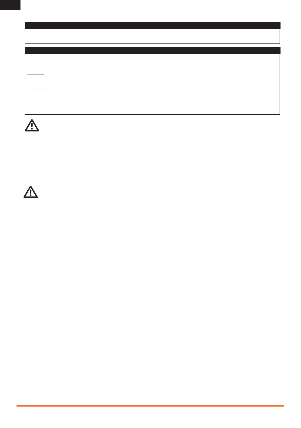
IDENTIFYING CONTROLS AND SWITCHES
Function
A
Button A
B
Button B
C
Button C
D
Button D
E
Button E
F
LCD Screen
G
Roller Selector
Memory Card Port
H
(under rubber grip)
Press power switch J to
power ON the transmitter.
The Power LED (K) will
come on, a Spektrum logo
screen will show, then the
Main Screen will show on
the LCD screen (F).
I
Rubber Grip
J
Power Switch
K
Power LED
L
Battery Cover
M
Throttle Trigger
N
Steering Wheel
O
Antenna
Function
C
A
F
G
E
H
I
J
B
K
D
O
N
M
L
INSTALLING BATTERIES
A
1. Push in door a small amount to release the retaining tab , then remove door.
A
2. Correctly install 4 AA batteries, aligning battery polarity to diagram in transmitter’s battery case.
3. Align tabs on door with slots on transmitter and carefully install door on transmitter.
C
CAUTION: Do not remove transmitter batteries while model is powered on or while operating a model or loss of model
control, damage or injury can result.
4
B
Spektrum DX3C • Radio Instruction Manual
C
B
Page 5
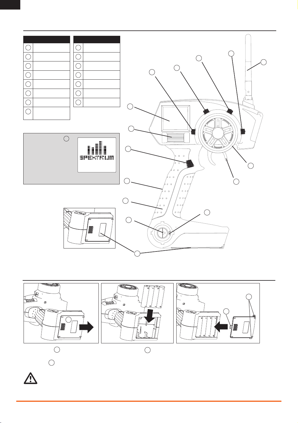
Rubber Grip
This transmitter includes 3 sizes of grips and the medium-size grip is installed at the factory. Inside the grip is a letter showing size:
L for large, M for medium and S for small.
Remove the grip by lifting the edge of the grip and pulling the grip away from the handle. Install a grip by aligning grip tabs with
handle slots and pressing the grip in place.
SD Memory Card
The DX3C features an SD card reader allowing your transmitter’s software to be
updated using an SD card (sold separately). Download upgrade software (when available) from the Spektrum website and transfer the software to your transmitter using
an SD card. To upload new software to your DX3C transmitter:
1. Remove the grip from the back of the transmitter handle.
2. Insert an SD card containing Spektrum update software in the
card reader port.
3. Power on your transmitter.
4. A Spektrum logo screen shows and a progress meter
will fill until upload of software is complete.
5. Remove the SD card from the transmitter.
6. Replace the grip on the transmitter handle.
7. The transmitter is updated and ready for use.
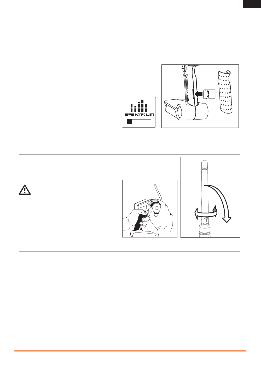
ANTENNA ROTATION
EN
Turn and bend the antenna at its hinge to point the tip of the antenna away from the
model. The strongest signal of the transmitter comes from the shaft of the antenna,
not the tip.
WARNING: Do not pick up the transmitter by the
antenna. Do not alter or put weight on the antenna.
Damage to antenna parts can decrease transmitter signal
strength, which can result in loss of model control, injury or
property damage.
RECEIVER INFORMATION
The DX3C features DSM technology and is compatible with Spektrum DSM, DSM2, and Marine surface receivers.
See www.spektrumrc.com for all compatible receivers.
Receiver Connection and Installation
Install the receiver using double-stick tape in the typical electric-powered model on the side opposite from the ESC.
Install the receiver using double-stick tape in the typical gas-powered model as far forward of the motor as possible.
Put the receiver antenna in an antenna tube and make sure the receiver’s antenna goes above the motor and other metal parts for
best reception of the transmitter signal.
Spektrum DX3C • Radio Instruction Manual
5
Page 6
EN
F
ENTER
Battery Low
B
A
D
C
4.3V
Warning
Inactivity
ModelMatch
The DX3C features ModelMatch technology that prevents operating a model using the wrong model memory. During the binding
process, the receiver stores code that is assigned to the specific model that is currently selected in the transmitter. For example: if
the model that is selected in the transmitter is model #3, when a receiver is bound to that transmitter, the receiver will only operate
when model #3 is selected. If another model memory is selected (model #5 for example) the receiver will not connect. If model #3
is again selected in the transmitter, the receiver bound to model #3 will connect. ModelMatch prevents operating a model using the
wrong model memory.
WARNING SCREENS
Low Battery Alarm
An alarm will sound and a warning screen will show when the transmitter’s battery power goes
below a set limit. This alarm reminds a user to bring a model under full control, power off the transmitter and replace batteries. Press the Roller to stop the alarm and go to the Main Screen.
Set the low battery limit using the System Screen.
A Warning title
B Battery voltage which is under the set limit
C Animated arrow pointing to Roller below screen
D Image of roller below screen.
Inactivity Alarm
An alarm will sound and a warning screen will show when the transmitter has been left on
(approximately 10 minutes) without control movement. Moving any control will stop the alarm.
This alarm reminds users to power off the transmitter and save battery power.
MAIN SCREEN
The Main Screen displays information about the selected model such as trim positions, timer, the model selected, battery voltage,
etc. This screen shows the Timer only when activated.
Note: An alarm will sound when the transmitter’s battery voltage goes below the value set in the System Screen.
Note: An alarm will sound when the timer gets to the limit (DOWN) set in the Timer Screen.
While in any screen, press and hold the Rolling Selector for more than 3 seconds to return to the Main Screen.
Throttle (TH) and Steering (ST) trim positions show as blocks in rectangles.
A Transmitter battery voltage.
B Name assigned to the Model memory.
C Active Model memory number (20 available).
D User Name.
E Position of Throttle (Th) trim.
F Position of Steering (St) trim.
G Timer (when activated).
H Model number and name (Timer activated).
6
D
Spektrum Th
C
Model 1:
B
NAME-O1
A
5.7V
St
G
XXX T
1:
F
TM
E
10:00
A
Th
D
5.7V
St
E
Spektrum DX3C • Radio Instruction Manual
Page 7

List
Select
Reverse
Travel
Expo
Bind
Sub-Trim
Timer
Name
Switch
System
Copy
Reset
Mixing
Steer Mix
System
Username
RS Port
Alert
Contrast
Buzzer
Lang
RF Mode
About...
PROGRAMMING GUIDE
Turn
Press
Press
EN
Roller and LCD Screen Use
This transmitter features one-touch programming using a
Rolling Selector. The Rolling Selector has three functions:
Pressing the Selector - enters the selected function.
Rolling the Selector - highlights function or changes settings
and values when selected.
Pressing and holding the Selector for more than 3 seconds
from any screen - returns the display to the Main Screen.
Programming always starts with a press on the selector, then a
roll, then a press, then a roll and so on.
Some racers find it convenient to use a thumb to make
programming changes. The roller’s location allows a racer to do
one-handed programming, controlling the model with one hand
while making programming adjustments with the other.
Press
Enter, Choose or
Exit
“Sticky” (GUI)
In the Travel, Expo, Mixing and Steer Mixing Screens, sticky
gooey (GUI) makes value adjustment easier. When you move
the channel control (the steering wheel or throttle trigger) to the
desired position and release, the value on the screen for that
side remains highlighted.
Move the control the opposite direction to highlight the other
value on the screen. You do not have to hold the control in the
desired position for the value to be changed. Highlight both values on the screen again by pressing the Rolling Selector twice
with the control centered.
List
The List Screen shows other screens to set programming in the transmitter.
A A dark box around with a clear symbol or text shows highlighted selection. Available
screens are Select, Reverse, Travel, Expo, Bind, Sub-Trim, Timer, Name, Switch,
System, Copy, Reset, Mixing and Steer Mix.
B Active Screen name shows at the top of the screen.
C Choosing this arrow will open the next higher screen, such as Main Screen or this List
Screen.
D A small bar shows relative position of highlighted screen name in the List.
List
Select
Reverse
Travel
Expo
Bind
Sub-Trim
Timer
Name
Switch
System
System
List
System
Copy
Reset
Mixing
Steer Mix
List
Turn
Move between options or
change value in an option
B
A
Model
Model
Reverse
Travel
Expo
Bind
Hold
Hold for 3 seconds and release
to move to a higher screen
List
C
D
Spektrum DX3C • Radio Instruction Manual
7
Page 8

EN
Select
Select function opens a model memory for control of a model
or adjustment of saved settings. If you haven’t programmed a
model memory, all settings will be at factory default.
CAUTION: Do NOT change the model in Model Select
while operating a model. Change of the model interrupts
transmitter signal to a receiver and may cause a crash.
A Model memory number (20 available).
B Model name (programmable in Name Screen).
Reverse
The Reverse function (also known as servo reversing) establishes the servo’s direction relative to the channel’s input (e.g.,
a right steering input should result in a right steering angle at
the model). Reverse is available on all three channels and is
normally the first function that is checked and adjusted during
programming. Movement of a control or switch is NOT changed.
Instead, a channel’s response to transmitter input is reversed.
Note: Your model manual may refer to this as changing transmitter control directions in the Control Test/Reverse Controls
section.
A Dark box shows direction servo is set (Normal is shown):
NOR=normal or REV=reverse.
B Box shows around selected text.
C Channels which can be reversed: Steering, Throttle or Aux
(auxiliary).
B
A
Reverse
B
A
Model
Model 1:
NAME-01
Steering
NOR REV
C
Travel
The Travel function supports precise endpoint adjustments in
each direction for each of the 3 channels (Steering, Throttle
and Aux (auxiliary).
A R (right)*.
B L (left)*.
C Box shows around selected text.
D Channel: (Steering, Throttle or Aux (auxiliary).
E Adjustable value (from 0 to 150%).
*Reference chart for options available for each channel:
Channel Top Bottom
Steering L (left) R (right)
Throttle B (brake) F (forward)
Aux H (high) L (low)
8
Travel
C
Steering
B
D
E
L 100%
A
R 100%
CAUTION: Before driving a model, always do a check of
the model’s response to changed Travel settings. Raise
vehicle so vehicle does not move on tires during testing.
Spektrum DX3C • Radio Instruction Manual
Page 9

Expo
The Exponential (Expo) function affects the response rate of the
steering, throttle and/or brake. A positive Steering Expo value, for
example, decreases steering sensitivity around neutral making it
easier to drive at high speeds in a straight line while still allowing for maximum turning radius. While sensitivity with positive
Expo is decreased around neutral, it increases the sensitivity
near the end of travel.
*Reference chart for options available for each channel:
Channel Top Bottom
Steering L (left) R (right)
Throttle B (brake) F (forward)
Expo
C
Steering
B
D
E
L 0%
A
R 0%
A R (right)*.
B L (left)*.
C Box shows around selected text.
D Channel: (Steering, Throttle or Aux (auxiliary).
E Adjustable value (from -100% to +100% (0 is factory
default or inhibit)).
EN
Bind
Binding is the process of teaching the receiver the specic
transmitter’s code called GUID (Globally Unique Identier) and
storing failsafe values. When a receiver is bound to a
transmitter/model memory, the receiver will only respond to that
specic transmitter/model memory (see ModelMatch for more
information).
Note: If a receiver is not bound to a specific model memory, it
will not operate.
Bind Transmitter to Receiver
1. Insert a bind plug in the receiver’s BIND port.
2. Power on the receiver and wait until the receiver LED begins
to blink (approximately 5 seconds).
3. Power on the transmitter.
4. Make sure the model number you desire shows on the Main
Screen. Go to the Model Select Screen to change the active
model number as needed.
5. Go to the transmitter’s Bind Screen and highlight BIND.
6. Move steering wheel, throttle trigger and AUX channel
(where used) to desired Failsafe positions and hold them in
that position during the bind process.
7. Press the Rolling Selector to start the bind process (which
also stores Failsafe positions).
8. BIND will ash on the screen for a few seconds then stop
and the receiver LED will show a solid light, indicating the
bind process is complete.
9. When the bind process is complete, remove bind plug and
store plug in a convenient place.
NOTICE: If the bind plug is not removed from the receiver,
the receiver will enter bind mode the next time the receiver is
powered on.
Failsafe
Failsafe positions are also set during binding. In the unlikely
event that the radio link is lost during use, the receiver will drive
the servos to their pre-programmed failsafe positions (normally
full brakes and straight steering). If the receiver is turned on
prior to turning on the transmitter, the receiver will enter the failsafe mode, driving the servos to their preset failsafe positions.
When the transmitter is turned on, normal control is resumed.
Failsafe servo positions are set during binding.
Note: Failsafe activates only in the event that signal is lost from
the transmitter. Failsafe will NOT activate in the event that receiver battery power goes down or power to the receiver is lost.
Bind
C
Model 1:
B
NAME-01
A
Bind
The Bind Screen shows the active model and supports binding
the active model memory to a receiver.
A Select Bind when a receiver is prepared for binding.
B Active model name.
C Active model number.
D A dark box around the text shows binding action.
D
Spektrum DX3C • Radio Instruction Manual
9
Page 10

EN
Sub-Trim
The Sub-Trim function allows electronic adjustment or centering
of each servo to get the servo arm exactly perpendicular to the
servo, or in the exact optimum desired position. Minor sub-trim
values can be used to correct this offset inaccuracy. Sub-trim is
adjustable for each of the 3 channels.
CAUTION: Use only small sub-trim values so a servo’s
maximum travel is NOT overdriven.
*Reference chart for options available for each channel:
Channel Description
Steering L (left) R (right)
Throttle B (brake) F (forward)
Aux H (high) L (low)
Sub-Trim
B
Steering
A
0
A Value for servo alignment (varies among channels).
* Range is 0 to 100 in both directions.
B Box shows around selected text.
C Channels: Steering, Throttle or Aux=Auxiliary.
C
Timer
The Timer function supports Up and Down timing. When started
by an assigned button, the time shows on the Main Screen.
Note: Refer to Switch Screen instructions for assigning a button
to the Timer (Button E on the grip handle is recommended).
Down timer – is the default timer type. The timer can be set
in 10-second increments to count down from 10 minutes.
Normally, this timer is programmed for the length of a race. The
timer’s default setting is 5 minutes runtime for electrics (battery
capacity) or gas-powered (fuel-tank capacity).
Start the timer by pressing the assigned timer button. When
the time expires, an alarm will sound until the timer button is
pressed (when Buzzer is not set to OFF). To pause or continue
the Down timer, press the timer button once. To reset the Down
timer to its pre-programmed value, press and hold the timer
button for more than 3 seconds.
Name
Assign a name for a model memory in this screen. 10 characters can be used to name a model. This name shows on the
Main Screen when an model memory is active.
Note: You can only change a model name when the model
memory is active.
A Marker showing selected character.
B Model Name (10 character spaces available).
C Active model memory.
Up timer - is started by pressing the timer button and counts up
from 00:00 seconds, functioning as a stopwatch. The Up timer
is useful for timing a fuel run to determine fuel mileage/pit stop
strategy. The Up timer can also be used for electrics to time the
run time of a battery pack for determining gear ratio and setup.
To pause or restart the Up timer, press the timer button. To reset
the Up timer to 00:00 press and hold the timer button for more
than 3 seconds.
Timer
B
Down
C
A
5:00
A Value for timer.
B Box shows around selected text.
C Options: Inhibit, Down and Up.
Name
C
Model 1:
B
NAME-01
A
10
Spektrum DX3C • Radio Instruction Manual
Page 11

Switch
Switch
A:Aux 3P
B:TH trim
C:ST trim
D:TMR ROSS
E:ST Rate
A
B
C
Lin (Linear)
ST Rate
100%
B
A
The Switch Screen lets you assign 5 available switches
to these special functions:
ST trim Assigns a switch to adjust center or neutral so
steering tracks straight
TH trim Assigns the throttle idle adjustment to switch. Ad-
just throttle neutral (idle) position for drag braking
or rolling idle for some models. Decreasing idle
can enable a drag brake. Increasing idle can keep
a model rolling until the brake is used.
Brake Assigns brake trim to switch. Full brake is the
default. Braking power can be decreased using this
trim on some models.
Aux Lin Assigns channel 3 (Auxiliary) to switch as linear
output (see servo illustration). This allows for
proportional adjustment of servo position. This is
particularly useful for fuel mixture control on gas
engines.
Aux 2P Assigns channel 3 (Auxiliary) to switch as 2-posi-
tion output (see servo illustration). This is useful
for forward and reverse transmissions and some
2-speed transmissions.
Aux 3P Assigns channel 3 (Auxiliary) to switch as 3-posi-
tion output (see servo illustration). This is useful
for forward, neutral and reverse transmissions and
some dig transmissions.
Note: Reverse and Travel Screens adjust
the endpoints and direction of the Auxiliary
channel.
EN
TMR ROSS Timer and ROSS* assigned to right and left sides of
a switch.
ROSS TMR ROSS and Timer assigned to right and left sides of
a switch.
TMR Timer start, pause, stop and reset assigned to a
switch
ROSS Remote start assigned to a switch
ST MIX Steering mix assigned to a switch
Inhibit No function assigned to switch
ST Rate Assigns Steering rate to a switch so a driver can
make on-the-y steering travel adjustments. Steering rate limits the amount of travel of the steering
servo
1
1
2
1 2
2P (2 position)
Steering Rate
Steering (ST) rate lets you quickly make steering travel adjustments using a designated switch (program switch A, B, C, D or E
on the Switch Screen). Steering rate limits the amount of travel
of the steering servo. Decreasing the rate decreases sensitivity
of steering control. Some drivers decrease this rate when driving
on an oval race course to decrease the amount of steering travel
‘on the y’. You can adjust the rate between 0–100%. Factory
default setting is 100%. The rate cannot be greater than 100%
and will never exceed the amount of steering travel set in the
Travel Screen.
Spektrum DX3C • Radio Instruction Manual
100
3
3P (3 position)
* LOSI ROSS (Remote Onboard Starting System)
A Switch letter (see transmitter illustration)
B Box shows around selected text
C Function assigned to the switch
Note: Assignment of switches in other screens changes what is
shown in this screen.
Note: The factory default switch assignments are shown here.
Reset of the transmitter returns switch assignments to these
functions.
Note: Refer to your model’s manual for recommended rate
settings.
A Steering rate
B Screen title
11
Page 12

EN
H
G
F
System
Contrast:20
Buzzer: Off
Lang:English
RF Mode:Std
About...
I
System
The System function lets you adjust transmitter interaction.
Selections affect all saved model memories.
A Username
You can program a user name with up to 10 characters. This
name shows on the Main Screen. User name defaults to
Spektrum.
In the System screen highlight the User Name and press the
roller to access the function. Use the roller to select the position,
then press the roller to access a character.
B RS Port
This sets the port (Bind or Aux (Auxiliary) on the receiver for
ROSS (Losi Remote Onboard Starting System) connection.
C Alert
You can set an alarm to sound when the battery voltage gets to
the limit set with the Alert. The range which can be set is from
0.0V to 6.2V. Battery voltage shows on the Main Screen.
CAUTION: Do not operate a model when the battery
voltage is below 4V.
D Contrast
The contrast function provides adjustment to the brightness ratio
of the lightest to the darkest part of the screen. You can set the
contrast to a value from 0 to 30 (0 is lightest and 30 is darkest).
E Buzzer
You can adjust sounds in loudness among Off, Low and High.
Note: Buzzer adjustment does not change sound level for
Inactivity or Low Battery warnings.
F Lang (Language)
You can select English, German (Deu.), French (Francais) or Italian (Italiano) as the language showing on transmitter screens.
G RF Mode
You can set this mode on either Std or FR. Std is the standard
RF mode. FR is the France RF mode and should only be selected
when the transmitter is used in France.
System
Username
A
RS Port:Bind
B
Alert:4.1V
C
Contrast:20
D
Buzzer: Off
E
System
Contrast:20
Buzzer: Off
Lang:English
F
RF Mode:Std
G
About...
I
H
H About....
This shows the release level of the transmitter’s software. Refer
to Memory Card instructions for updating transmitter software.
I
A small bar shows relative position of highlighted screen name
in the list.
Copy
The Copy function shares active model memory settings with a
selected model memory space. This is useful for saving setups
for one model to adjust programming for track conditions or
model setups.
A Choosing No returns to the List Screen
B Name of destination model memory
C Name of active or source model memory
D Active or source model memory number
E Destination model memory number
F Box shows selected text
G Choosing Yes saves active model settings to the selected
model memory
CAUTION: Model information saved in a memory is
erased and overwritten by active model settings using
this Copy function.
12
Copy
From: 1
NAME-O1
D
C
To : 3
E
NAME-O3
B
No Yes
A
Spektrum DX3C • Radio Instruction Manual
F
G
Page 13

Reset
Mixing
ST > Aux
Rate:
50% 50%
Trim: Inh
C
D
E
F
G
The Model Reset function restores factory default settings for
the active model memory.
A Choosing Yes affirms erasing saved settings for the active
model memory and return of factory defaults.
B A box shows around selected text.
C Choosing No returns to the List Screen.
CAUTION: Model information saved in a memory is
erased when that model memory is copied over or reset
to factory default settings.
Mixing
The Mixing function lets Steering, Throttle or Aux Channel follow
control input made to the Steering, Throttle or Aux channel.
When a mix is enabled and the assigned input control is moved,
the master (primary) channel sends output at the same time the
slave (secondary) channel sends output. Output is sent to the
model in the direction and to the position assigned in the Mixing
Screen.
Note: You can only select the Aux channel as Slave in this
screen when Steer Mix is inhibited.
Mixing default setting is inhibit (Inh). When anything other than
Inh is selected, you can make additional adjustments on the
Mixing Screen.
A Inh must be changed to enter other mixing values.
B A box shows around selected text.
C This rate value sets the amount of slave servo travel and can
be set from -125% to +125%. A negative value results in
the slave channel moving in a direction opposite the direction of the primary channel.
D The primary or master channel can be either ST (Steering),
TH (Throttle) or AUX (Auxiliary).
E The secondary or Slave channel can be set on ST, TH or
Aux (Channel 3 Auxiliary).
F This rate value can be set from -125% to +125%.
G This can be set on Inh (inhibit) or Act (activate) When set to
Act, trim changes on the master channel will also change
the slave channel trim.
NOTICE: Before driving a model, always do a check of the
model’s response to mix settings. Raise vehicle so vehicle does
not move on tires during testing.
Reset
C
No
B
Yes
A
Mixing
B
Inh
A
Mixing
D
ST > Aux
Rate:
C
50% 50%
Trim: Inh
CAUTION: A negative value results in the secondary
channel moving in a direction opposite the direction of
the primary channel.
E
F
G
EN
Spektrum DX3C • Radio Instruction Manual
13
Page 14

EN
Steer Mix
Type: Dual
Trim: Act
Rate:
100% 100%
C
A
D
E
F
Steer Mix
Type: Dual
Trim: Act
Rate:
100% 100%
C
A
D
E
F
Steer Mix
Steer Mix function supports mixing Steering to Auxiliary channel
so the Auxiliary input follows input to Steering.
Steer mix is usually used to manage how much rear steering
follows front steering inputs.
Typically, this mixing function is used with 2 steering servos on
trucks (front and rear servos). F/R (front/rear) type supports 2
mix rates so crab steering and four-wheel steering can be used
momentarily with a switch. Dual type supports full-time mixing
without a switch.
Note: Assigning a switch in this screen changes the assignment
of that switch in the Switch Screen. Default switch for F/R is E.
Note: When Steer Mix is not inhibited, the Auxiliary channel
cannot be selected as Slave in the Mixing screen..
Note: When Steer Mix is assigned to a switch, moving the
switch accesses the alternate set of rate values. Adjust positive
(+) and negative (-) values for conventional or crab steering.
NOTICE: Before driving a model, always do a check of the
model’s response to steer mix settings. Raise vehicle so vehicle
does not move on tires during testing.
A A box shows around selected text.
B Inh inhibits steer mixing.
C This rate value for left steering sets the amount of Auxiliary
servo travel and can be set from -125% to +125%. A
negative value results in the Auxiliary channel moving in a
direction opposite the direction of the Steering channel.
D Dual is full-time front/rear steer mixing at the programmed
rates.
E When Trim is Act (activated), the ST trim is applied to both
the ST and AUX channels. When Trim is Inh (inhibit), the ST
trim is only applied the ST channel. Act is the default.
F This rate value for right sets the amount of Auxiliary servo
travel and steering can be set from -125% to +125%. A
negative value results in the Auxiliary channel moving in a
direction opposite the direction of the Steering channel.
G Position 1 for the assigned switch.
H Position 2 for the assigned switch.
I F/R enables switch assignment for the programmed steering
mix rates 1 and 2.
J The assigned switch (A, B, C, D or E) lets a driver enable
front/rear steering mix rate 1 or 2.
Steer Mix
B
Type: Inh
A
Steer Mix
A
C
Steer Mix
A
Type: F/R
Trim: Act
Switch:E
G
H
1: 100% 100%
2:-100% -100%
C
Type: Dual
Trim: Act
Rate:
100% 100%
D
E
F
I
E
J
F
14
Spektrum DX3C • Radio Instruction Manual
Page 15

TROUBLESHOOTING GUIDE
Problem Possible Cause Solution
The system will
not connect
The receiver goes
into failsafe mode a
short distance away
from the transmitter
Receiver quits
responding during
operation
Receiver loses its
bind
Receiver taking
longer than usual to
link with transmitter
Transmitter and receiver too near each other Move transmitter 8 to 12 feet (2.4 to 3.6m) from
receiver
Transmitter and receiver too near large metal
objects (vehicles, etc.)
Selected model is not bound in transmitter Make sure correct model memory is selected and that
Transmitter accidentally put in bind mode so
receiver is no longer bound
Check the receiver antenna to be sure it is not
cut or damaged
Low battery voltage Completely recharge battery
Loose or damaged wires or connectors between
battery and receiver
Transmitter accidentally put in bind mode, ending
bind to receiver
Transmitter and receiver are operating on Marine
model
Move away from large metal objects (vehicles, etc.)
transmitter is bound to the model
Rebind transmitter and receiver
Replace or contact Horizon Product Support
Make sure receiver antenna is in an antenna tube and
is above vehicle
Do a check of the wires and connection between
battery and receiver. Repair or replace wires and/or
connectors
Bind transmitter to receiver
Marine receivers can take longer to link with
transmitter
EN
FCC INFORMATION
This device complies with part 15 of the FCC rules. Operation
is subject to the following two conditions: (1) This device may
not cause harmful interference, and (2) this device must accept
any interference received, including interference that may cause
undesired operation.
CAUTION: Changes or modifications not expressly
approved by the party responsible for compliance could
void the user’s authority to operate the equipment.
This product contains a radio transmitter with wireless technology which has been tested and found to be compliant with
the applicable regulations governing a radio transmitter in the
2.400GHz to 2.4835GHz frequency range.
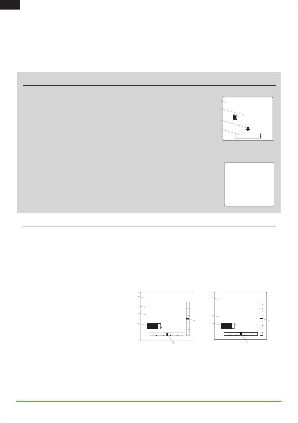
Antenna Separation Distance
When operating your Spektrum transmitter, please be sure to
maintain a separation distance of at least 5 cm between your
body (excluding ngers, hands, wrists, ankles and feet) and the
antenna to meet RF exposure safety requirements as determined
by FCC regulations.
The illustrations below show the approximate 5 cm RF exposure
area and typical hand placement when operating your Spektrum
transmitter.
Spektrum DX3C • Radio Instruction Manual
15
Page 16

EN
WARRANTY AND REPAIR POLICY
Warranty Period
Exclusive Warranty- Horizon Hobby, Inc., (Horizon) warranties
that the Products purchased (the “Product”) will be free from
defects in materials and workmanship for a period of 1 year
from the date of purchase by the Purchaser.
1 Year Limited Warranty
Horizon reserves the right to change or modify this warranty without notice and disclaims all other warranties,
express or implied.
(a) This warranty is limited to the original Purchaser (“Purchaser”) and is not transferable. REPAIR OR REPLACEMENT AS
PROVIDED UNDER THIS WARRANTY IS THE EXCLUSIVE REMEDY
OF THE PURCHASER. This warranty covers only those Products purchased from an authorized Horizon dealer. Third party
transactions are not covered by this warranty. Proof of purchase
is required for all warranty claims.
(b) Limitations- HORIZON MAKES NO WARRANTY OR REPRESENTATION, EXPRESS OR IMPLIED, ABOUT NON-INFRINGEMENT,
MERCHANTABILITY OR FITNESS FOR A PARTICULAR PURPOSE
OF THE PRODUCT. THE PURCHASER ACKNOWLEDGES THAT
THEY ALONE HAVE DETERMINED THAT THE PRODUCT WILL
SUITABLY MEET THE REQUIREMENTS OF THE PURCHASER’S
INTENDED USE.
(c) Purchaser Remedy- Horizon’s sole obligation hereunder shall
be that Horizon will, at its option, (i) repair or (ii) replace, any
Product determined by Horizon to be defective. In the event of
a defect, these are the Purchaser’s exclusive remedies. Horizon
reserves the right to inspect any and all equipment involved in a
warranty claim. Repair or replacement decisions are at the sole
discretion of Horizon. This warranty does not cover cosmetic
damage or damage due to acts of God, accident, misuse, abuse,
negligence, commercial use, or modification of or to any part
of the Product. This warranty does not cover damage due to
improper installation, operation, maintenance, or attempted
repair by anyone other than Horizon. Return of any Product by
Purchaser must be approved in writing by Horizon before shipment.
Damage Limits
HORIZON SHALL NOT BE LIABLE FOR SPECIAL, INDIRECT OR
CONSEQUENTIAL DAMAGES, LOSS OF PROFITS OR PRODUC-
TION OR COMMERCIAL LOSS IN ANY WAY CONNECTED WITH
THE PRODUCT, WHETHER SUCH CLAIM IS BASED IN CONTRACT,
WARRANTY, NEGLIGENCE, OR STRICT LIABILITY. Further, in no
event shall the liability of Horizon exceed the individual price of
the Product on which liability is asserted. As Horizon has no control over use, setup, final assembly, modification or misuse, no
liability shall be assumed nor accepted for any resulting damage
or injury. By the act of use, setup or assembly, the user accepts
all resulting liability.
If you as the Purchaser or user are not prepared to accept the
liability associated with the use of this Product, you are advised
to return this Product immediately in new and unused condition
to the place of purchase.
Law: These Terms are governed by Illinois law (without regard to
conict of law principals).
Warranty Services
Questions, Assistance, and Repairs
Your local hobby store and/or place of purchase cannot provide
warranty support or repair. Once assembly, setup or use of the
Product has been started, you must contact Horizon directly. This
will enable Horizon to better answer your questions and service
you in the event that you may need any assistance. For questions or assistance, please direct your email to productsupport@
horizonhobby.com, or call 877.504.0233 toll free to speak to a
Product Support representative. You may also find information on
our website at www.horizonhobby.com.
Inspection or Repairs
If this Product needs to be inspected or repaired, please use the
Horizon Online Repair Request submission process found on our
website or call Horizon to obtain a Return Merchadise Authoriza-
tion (RMA) number. Pack the Product securely using a shipping
carton. Please Note that original boxes may be included, but
are not designed to withstand the rigors of shipping without
additional protection. Ship via a carrier that provides tracking
and insurance for lost or damaged parcels, as Horizon is not
responsible for merchandise until it arrives and is accepted at
our facility. An Online Repair Request is available at www.horizonhobby.com http://www.horizonhobby.com under the Repairs
tab. If you do not have internet access, please contact Horizon
Product Support to obtain a RMA number along with instructions
for submitting your product for repair. When calling Horizon, you
will be asked to provide your complete name, street address,
email address and phone number where you can be reached
during business hours. When sending product into Horizon,
please include your RMA number, a list of the included items,
and a brief summary of the problem. A copy of your original
sales receipt must be included for warranty consideration. Be
sure your name, address, and RMA number are clearly written
on the outside of the shipping carton.
Notice: Do not ship batteries to Horizon. If you have any
issue with a battery, please contact the appropriate
Horizon Product Support office.
Warranty Inspection and Repairs
To receive warranty service, you must include your
original sales receipt verifying the proof-of-purchase date.
Provided warranty conditions have been met, your Product will
be repaired or replaced free of charge. Repair or replacement
decisions are at the sole discretion of Horizon.
Non-Warranty Repairs
Should your repair not be covered by warranty the repair
will be completed and payment will be required without
notification or estimate of the expense unless the expense exceeds 50% of the retail purchase cost. By submit-
ting the item for repair you are agreeing to payment of the repair
without notification. Repair estimates are available upon request.
You must include this request with your repair. Non-warranty
repair estimates will be billed a minimum of ½ hour of labor.
In addition you will be billed for return freight. Horizon accepts
money orders and cashiers checks, as well as Visa, MasterCard,
American Express, and Discover cards. By submitting any item
to Horizon for inspection or repair, you are agreeing to Horizon’s
Terms and Conditions found on our website under the Repairs
tab.
16
Spektrum DX3C • Radio Instruction Manual
Page 17

WARRANTY AND SERVICE CONTACT INFORMATION
Country of Purchase Horizon Hobby Address Phone Number / Email Address
Horizon Service Center
United States of
America
United Kingdom Horizon Hobby Limited
Germany Horizon Technischer Service
France Horizon Hobby SAS
(Electronics and engines)
Horizon Product Support
(All other products)
4105 Fieldstone Rd
Champaign, Illinois, 61822 USA
4105 Fieldstone Rd
Champaign, Illinois, 61822 USA
Units 1-4 Ployters Rd
Staple Tye
Harlow, Essex
CM18 7NS, United Kingdom
Hamburger Str. 10
25335 Elmshorn, Germany
14 Rue Gustave Eiffel
Zone d’Activité du Réveil Matin
91230 Montgeron
877-504-0233
Online Repair Request:
visit www.horizonhobby.com/repairs
877-504-0233
productsupport@horizonhobby.com
+44 (0) 1279 641 097
sales@horizonhobby.co.uk
+49 4121 46199 66
service@horizonhobby.de
+33 (0) 1 60 47 44 70
infofrance@horizonhobby.com
PARTS CONTACT INFORMATION
Country of Purchase Horizon Hobby Address Phone Number / Email Address
United States Sales
United Kingdom Horizon Hobby Limited
Germany Horizon Hobby GmbH
France Horizon Hobby SAS
4105 Fieldstone Rd
Champaign, Illinois, 61822 USA
Units 1-4 Ployters Rd
Staple Tye
Harlow, Essex
CM18 7NS, United Kingdom
Hamburger Str. 10
25335 Elmshorn, Germany
14 Rue Gustave Eiffel
Zone d’Activité du Réveil Matin
91230 Montgeron
800-338-4639
sales@horizonhobby.com
+44 (0) 1279 641 097
sales@horizonhobby.co.uk
+49 4121 46199 60
service@horizonhobby.de
+33 (0) 1 60 47 44 70
infofrance@horizonhobby.com
EN
COMPLIANCE INFORMATION FOR THE EUROPEAN UNION
AT BG CZ CY DE
DK ES FI FR GR
HU IE IT LT LU
LV MT NL PL PT
RO SE SI SK UK
Declaration of Conformity
(in accordance with ISO/IEC 17050-1)
No. HH2011032301
Product(s): Spektrum DX3C Transmitter
Item Number(s): SPM3300
Equipment class: 2
The object of declaration described above is in conformity with the
requirements of the specifications listed below, following the provi-
sions of the European R&TTE directive 1999/5/EC:
EN 300-328 V1.7.1
EN 301 489-1 V1.7.1: 2006
EN 301 489-17 V1.3.2: 2008
EN 60950-1:2006+A11
Signed for and on behalf of:
Horizon Hobby, Inc.
Champaign, IL USA
March 23, 2011
International Operations and Risk Management
Steven A. Hall
Vice President
Horizon Hobby, Inc.
Instructions for disposal of WEEE
by users in the European Union
This product must not be disposed of with
other waste. Instead, it is the user’s responsibility to dispose of their waste equipment by
handing it over to a designated collections
point for the recycling of waste electrical and
electronic equipment. The separate collection and recycling of your waste equipment at the time of
disposal will help to conserve natural resources and ensure
that it is recycled in a manner that protects human health
and the environment. For more information about where
you can drop off your waste equipment for recycling, please
contact your local city office, your household waste disposal
service or where you purchased the product.
Spektrum DX3C • Radio Instruction Manual
17
Page 18

© 2011 Horizon Hobby, Inc.
The Spektrum trademark is used with permission of Bachmann Industries, Inc.
All other marks and logos are trademarks or registered trademarks of Horizon Hobby, Inc.
US 7,391,320. Other patents pending.
www.spektrum-rc.com
2/11 28844 SPM3300
 Loading...